

Page 1
INSTALLATION INSTRUCTIONS
AC1
DC CONTROLLED SWITCHED AC OUTLET
The AC1 is a DC voltage controlled AC outlet, capable of switching up to 15 Amperes of continuous current
to a device or power strip. It is intended primarily to provide common and zone AC power management in
conjunction with the CO & STATUS ports of the ZPR68 and ZPR68-10. It is usable, however, in any
application where it is desired to have an AC outlet turned on and off by a DC control voltage.
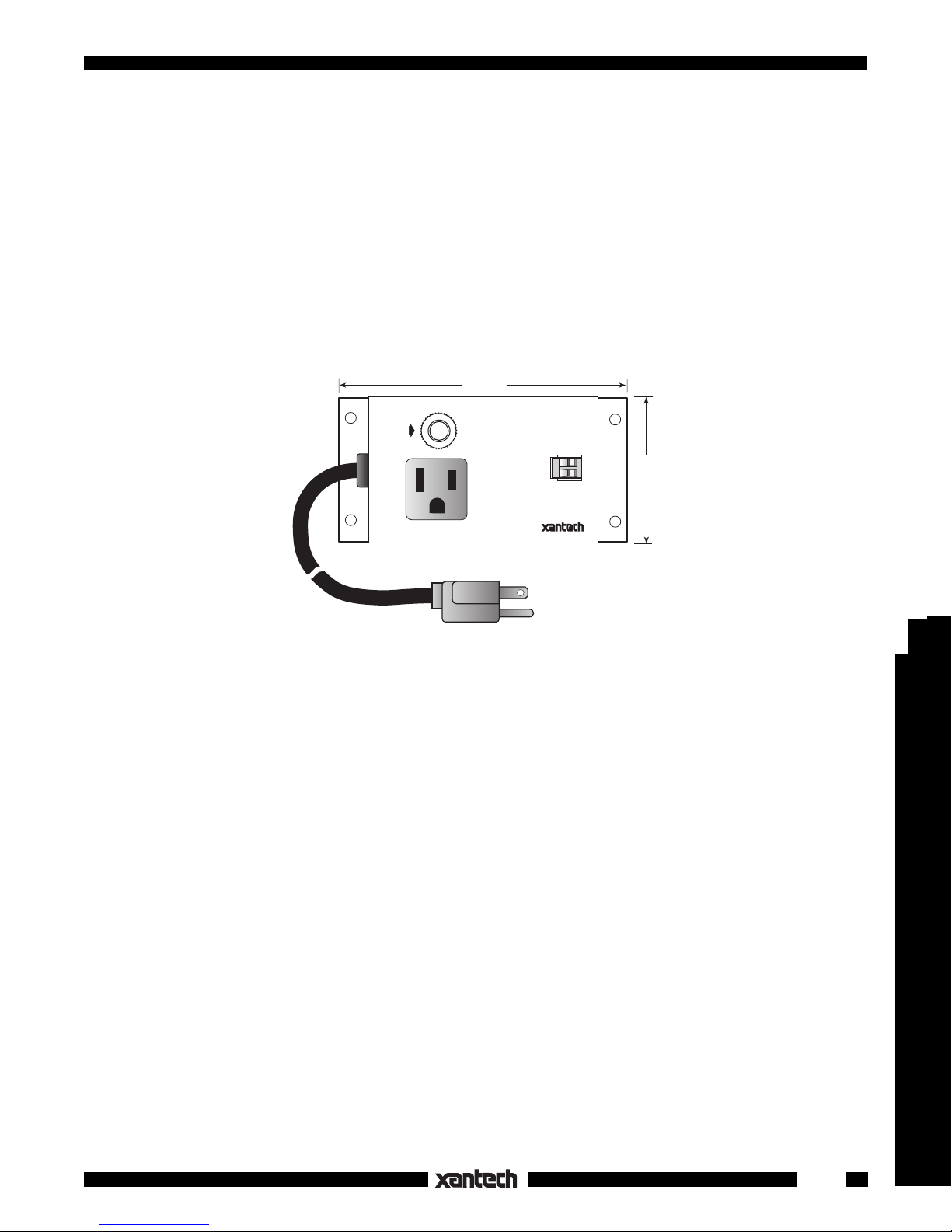
4-15/16"
AC1
RESET
120 VAC 60 HZ
1800 WATTS MAX.
SWITCHED AC OUTLET
15
Top View
CONTROL
INPUT
5 to 30 Volts DC
+
–
2-1/2 "
To 120 V AC
Fig. 1 The AC1
SPECIFICATIONS
• Maximum Switching Current: 15 Amps continuous, 30 Amps peak inrush, at 120 VAC, 60 Hz.
• AC Circuit Breaker: Opens if AC current exceeds 15 Amps. Push-to-Reset button.
• AC Power Cord: 120 VAC 16 gauge 5 ft., 3-conductor.
• Standby AC Line Current: < 2 mA (< .24 Watts).
• Control Input: Plug-in screw-type terminals for two-conductor connections. Handles wire sizes from 24
to 12 gauge.
• Control Input Turn-ON Voltage Range: 5 to 30 Volts DC, @1.5 mA/V.
• Control Input Turn-OFF Voltage: <2 Volts DC.
• Flanges, plus supplied screws, permit easy mounting to flat surfaces.
• Dimensions: 4-15/16" L x 2-1/2" W x 2-5/8" H (125mm x 64mm x 67mm)
INSTALLATION
The AC1 provides a convenient means to manage the power ON/OFF status of "Power Line Switchable"
components in a ZPR68-10 multi-zone system. Typical connections are shown in Fig. 2.
"Power Line Switchable" components are those that have manual power switches that can be left "ON" or
those that "remember" their "ON" condition when their power cords are unplugged.
Remote Control Switchers
1
Page 2
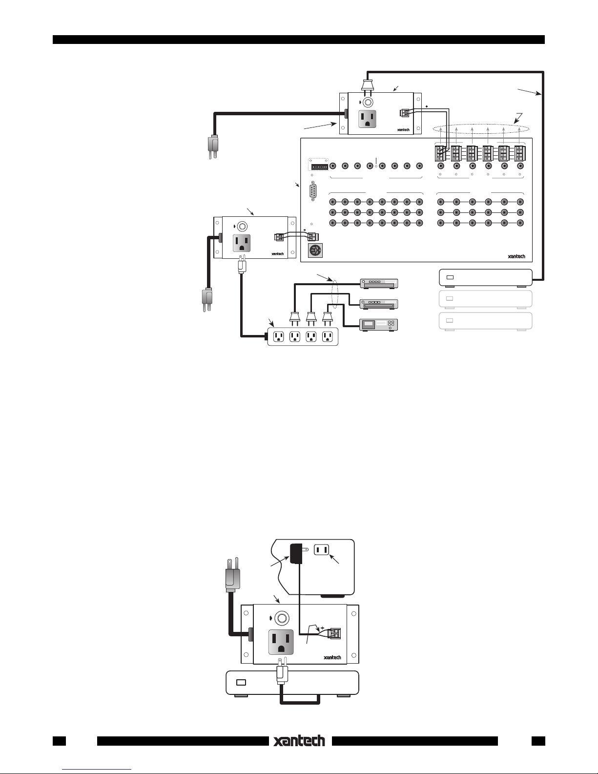
Fig. 2 Using AC1's in a ZPR68-10 System
To 120 V AC
(unswitched)
RESET
To 120 V AC
(unswitched)
Repeat this connection system
with additional AC1's for the
remaining zones as desired.
ZPR68-10
AC1
AC1
SWITCHED AC OUTLET
15
120 VAC 60 HZ
1800 WATTS MAX.
CONTROL
INPUT
+
–
5 to 30 Volts DC
AC Cords for
"Power Line Switchable"
Common Sources
AC Power
Strip
RESET
15
120 VAC 60 HZ
1800 WATTS MAX.
ZPR68-10
SIX ZONE EIGHT SOURCE REMOTE PREAMP
COMMON IR LEVEL
12345678
HI
LO
1 2 3 4 5 6 7 8
IR CONFIRM
12345678
VIDEO
COM
PORT
L
AUDIO
POWER
R
CO
G
POWER
SUPPLY
COMMON IR INDICATOR
COMMON IR OUTPUTS
SOURCE INPUTS
Laser Disc
CD Changer
Cassette DecK
COMMON
SOURCES
AC1
SWITCHED AC OUTLET
AC1
CONTROL
INPUT
5 to 30 Volts DC
AC Cords for "Power Line Switchable"
Zone Amplifiers and/or Zone Dedicated
Source Components
See ZPR68-10 "INSTALLATION
+
–
STATUS
VIDEO
AUDIO
INSTRUCTIONS" for other typical
system connections.
+12V
GND
INPUT
L
R
ZONE CONTROL - IR INPUTS
123456
ZONE IR OUTPUTS
ZONE OUTPUTS
ZONE STEREO
POWER AMPLIFIERS
The Fig. 2 example works as follows:
• The Zone power amplifier (and other zone dedicated components, if used) is switched ON when a ZPR6810 INPUT command turns a zone ON [STATUS terminal goes high (+12V)].
• The Zone power amplifier (and other zone dedicated components, if used) is switched OFF when a
ZPR68-10 OFF command turns a zone OFF [STATUS terminal goes low (0V)].
• The Common Source components are switched ON when the first ZPR68-10 zone is turned ON [CO
terminal goes high (+12V)].
• The Common Source components are switched OFF when the last ZPR68-10 zone is turned OFF [CO
terminal goes low (0V)].
Another excellent application for the AC1 is to switch components that draw more power than is available
from the switched AC outlet on the rear of A/V receivers, preamps, etc. Fig. 3 illustrates such a system:
To 120 V AC
(unswitched)
786-00
Power
Supply
SWITCHED
AC Outlet on
Pre-amp, etc.
AC1
AC1
15
120 VAC 60 HZ
1800 WATTS MAX.
SWITCHED AC OUTLET
White Striped
Side
CONTROL
INPUT
5 to 30 Volts DC
+
–
RESET
Fig. 3 Switching Higher Power Units
2
High Power
Amplifier
AC1
2-13-01
Rev.C
 Loading...