

Page 1
INSTALLATION INSTRUCTIONS
794 & 797
INTERFACE MODULES
The Model 794 or 797 allows any of the Xantech 3-wire IR receivers, keypads and control systems to
connect directly to the serial remote control input jack found on many audio/video components. This
eliminates the need for attaching an emitter to the front panel of the unit. The installer, by choosing the
correct model number, suffix number and DIP switch settings, may use these modules to control many
components.
INSTALLATION
• Review all tables 1, 2, & 3 to make sure you select the correct interface. The model number suffix generally
specifies which INTERFACE CABLE is supplied with the unit (see Tables 1, 2 & 3).
Do Not
•
cable is used.
Do Not
•
• There are ten DIP switches on the 794 and two on the 797. When the 794 or 797 is driven by a Model
390 Blast-IR or Model 792 Power Module, switch S1 must be in the 0 (off) position.
• The 794 and 797 are designed to supply power to Xantech 3-wire IR Receivers and keypads. Connect
them directly to the IN, GND1 and +12V terminals. The IN and GND1 terminals may also be connected
to any Xantech emitter output port.
• Use a 781RG or 782-00 power supply to power the 794 and 797 by plugging them into the +12V jack.
You may also power them from other Xantech devices in a system by running +12 V and Gnd jumper leads
from the other device to the +12V and GND2 terminals on the 794 and 797.
• If the plug on the 781RG or 782 power supply does not fit the +12V jack on the 794 or 797, simply remove
the plug and connect the white striped wire to +12V and the black wire to GND2 on the 794 or 797
terminals.
MODEL 794
• Switch S3 should be in the 1 (on) position in most
installations.
• When multiple 794’s are connected, or when ground
loops are encountered, set S3 to the 0 (off) position.
• Switch S2, and S4 through S10, should be set according to Table 1, page 2. For products not listed,
contact Xantech Technical Support. New versions
are added from time to time.
MODEL 797
• Switch S2 should be in the 1 (on) position in most
installations. When multiple 797’s are connected or
when ground loops are encountered, set S2 to the 0
(off) position.
• In general, set S1 and S2 according to Table 2, next
page. For products not listed, contact Xantech Technical Support. New versions are added from time to
time.
extend the cable supplied with the 794 or 797. The unit may not operate reliably when a longer
plug the 794 or 797 into anything until all switches are set.
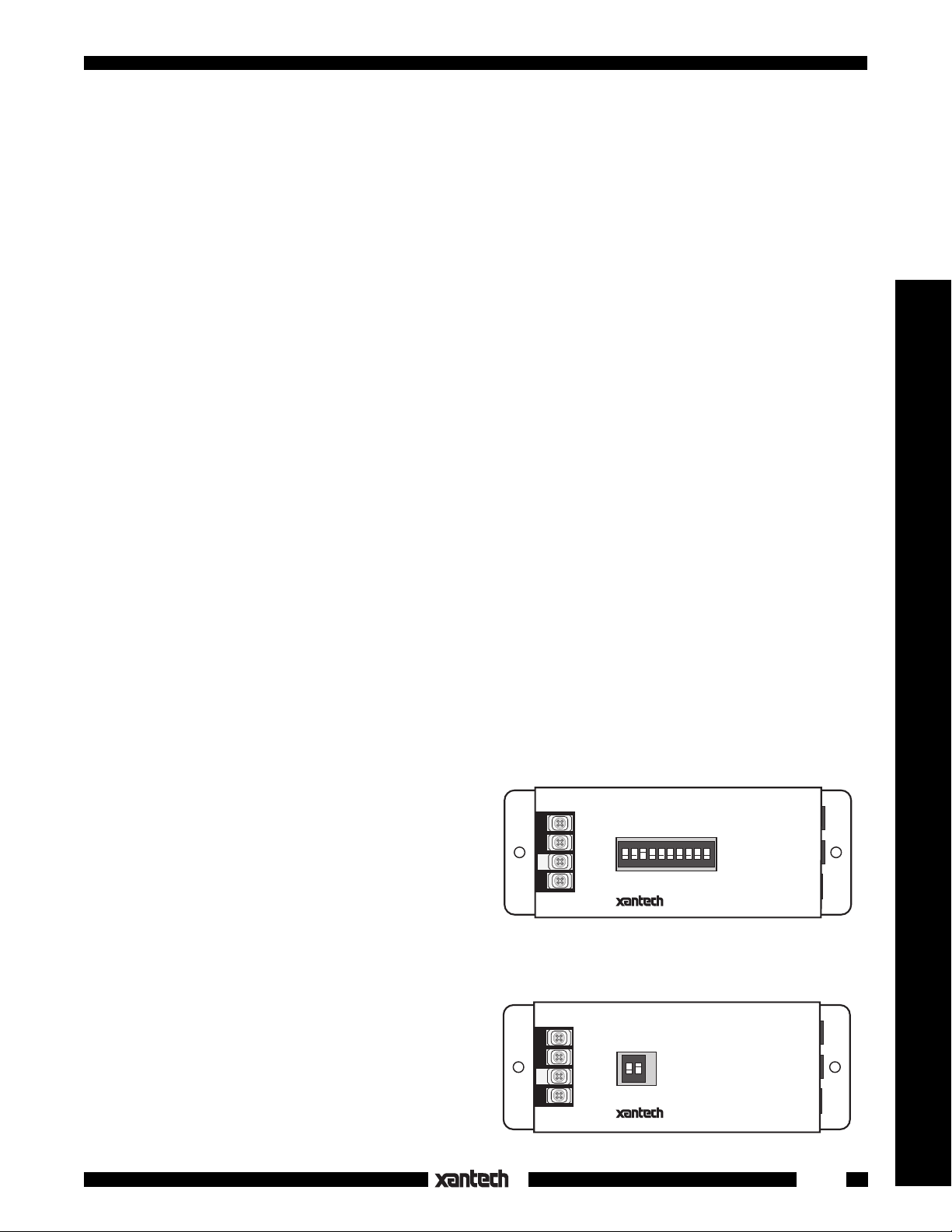
794
UNIVERSAL INTERFACE
IR IN
GND1
GND2
+12V
ON
1 2 3 4 5 6 7 8 910
12345678910
1 (ON)
0 (OFF)
Fig. 1 794-00
797 SERIES
UNIVERSAL INTERFACE
IR IN
GND1
GND2
+12V
ON
1 2
12
1 (ON)
0 (OFF)
Fig. 2 797-00
SENDER/
EMITTER
OUTPUT
+12V
SENDER/
EMITTER
OUTPUT
+12V
1
Modules & Connecting Blocks
Page 2

The following diagram, Fig. 3, illustrates a typical application of the 794 along with a 780-10 IR Receiver
to control an A/V receiver.
• The INTERFACE CABLE must always be plugged into the OUTPUT jack of the the 794,
never the
SENDER/EMITTER jack.
• The SENDER/EMITTER jack is used when you need to control a component with an emitter -- in this case
a VCR.
• If you use a Model 797, you would connect it in exactly the same way.
VCR
283M
Emitter
A/V Receiver
Plug into "Multiroom",
"Sensor IN ", "Serial In",
etc. jack on rear panel
of A/V component
Power Supply
J-BOX RECEIVER
+12 VDC
IR OUT
GND
J-Box IR Receiver
3-wire IR Receiver
780-10
3-Conductor
Cable
780-10
(or other Xantech
or Keypad)
794
UNIVERSAL INTERFACE
IR IN
GND1
ON
GND2
1 2 3 4 5 6 7 8 910
12345678910
+12V
1 (ON)
0 (OFF)
SENDER/
EMITTER
OUTPUT
INTERFACE
CABLE
+12V
781RG
Fig. 3
NOTE: A wire may be required between the GND2 screw of the 794 or 797 and a ground connection
(chassis screw) on the device being controlled. Refer to notes 2 and 4, page 2.
TABLE 1 - 794 Series Interfaces
LEDOM&DNARB#ELUDOMECAFRETNIELBACECAFRETNI 123456789 01
)4etonees(
DAN05-497
DOOWREHS01-497
008BFG,II005-PTGMOCDA
4XPSSECCAOIDUA01-497
71-TCREVRAC01-497
92-TC,42-TC,598RHREVRAC
)818ledoM(TNIOPRETNUOC01-497
)sledoMredlO(NONED01-497
)1/052PV,1/002DL(AJDUORAF01-497
)kcaJrosneSRI/W(ETAGSOF07-497
SISEHTNYSLBJ
)kcaJrosneSRIhtiW(
)A1PVA(NODRAKNAMRAH07-497
)srehto&164-R(ARECOYK05-497
)srehtoemos&231-XM(HSOTNIcM01-497
)1etonees(ATIKAM06-497
egnarOdnaRMneerG(ZTNARAM
)5-CR&skcajnIetomeR
)kcaJmm5.3htiW(IHCIMAKAN01-497
)NIDniP-6htiW(IHCIMAKAN04-497
)IRtoN(OYKNO01-497
)kcaJ"RM"htiW(OYKNO01-497
)5-CR(06-RFSPILIHP05-497
)2etonees-kcaJ
MOOR-ITLUMhtiWllA(REENOIP
)3etonees("SlortnoC"YNOS01-497
)3etonees(RCVYNOS01-497
)3etonees(VTRBXYNOS01-497
METSYSTSDYNOS01-497
"SCRIS"niP-4/WTSD-NONYNOS08-497
2CMAERTSDNUOS07-497
2
03-497
05-497
07-497
05-497
01-497
NORMAL SWITCH SETTINGS
otgulpinimonommm5.3
0010100010
elbacgulpNIDnip-5
otgulpinimoeretsmm5.3
0 1 100 0 10 10
elbacgulpinimoeretsmm5.3
otgulpinimoeretsmm5.3
0111010000
elbacgulpinimoeretsmm5.3
otgulpinimonommm5.3
0 1 10 10 00 10
elbacgulponohpepyt-ACR
otgulpinimoeretsmm5.3
0011010001
elbacgulpinimoeretsmm5.3
otgulpinimoeretsmm5.3
0111010000
elbacgulpinimoeretsmm5.3
otgulpinimoeretsmm5.3
0011000101
elbacgulpinimoeretsmm5.3
otgulpinimoeretsmm5.3
0111010000
elbacgulpNID-iniMnip-5
otgulpinimoeretsmm5.3
0111010000
elbacgulpNID-iniMnip-5
otgulpinimoeretsmm5.3
0111010000
elbacgulpNID-iniMnip-5
otgulpinimonommm5.3
0111010000
elbacgulponohpepyt-ACR
otgulpinimoeretsmm5.3
0111010001
elbacgulpinimoeretsmm5.3
otgulpinimoeretsmm5.3
0010011000
elbacgulpraludoM9-JR
otgulpinimonommm5.3
0 1 10 10 00 10
elbacgulponohpepyt-ACR
otgulpinimonommm5.3
0011010001
elbacgulponohpepyt-ACR
otgulpinimoeretsmm5.3
0111010000
elbacgulpinimoeretsmm5.3
otgulpinimoeretsmm5.3
0111010000
elbacgulpNIDnip-6
otgulpinimoeretsmm5.3
0010001001
elbacgulpinimoeretsmm5.3
otgulpinimoeretsmm5.3
0111000100
elbacgulpinimoeretsmm5.3
otgulpinimonommm5.3
0 1 10 10 00 10
elbacgulponohpepyt-ACR
otgulpinimoeretsmm5.3
0111010001
elbacgulpinimoeretsmm5.3
otgulpinimoeretsmm5.3
0111010001
elbacgulpinimoeretsmm5.3
otgulpinimoeretsmm5.3
0 1 10 10 00 10
elbacgulpinimoeretsmm5.3
otgulpinimoeretsmm5.3
0010001010
elbacgulpinimoeretsmm5.3
otgulpinimoeretsmm5.3
0010100010
elbacgulpinimoeretsmm5.3
otgulpinimoeretsmm5.3
0011000101
elbacgulpinimoeretsmm5.3
otgulpinimoeretsmm5.3
0011010001
)SCRISstif(elbacgulpniP-4
otgulpinimoeretsmm5.3
0111010000
elbacgulpNID-iniMnip-5
794-00/797-00
Page 3

TABLE 2 - 797 Series Interfaces
LEDOM&DNARB#LEDOMECAFRETNIELBACECAFRETNI12
6CSSDA04-797
.cte
).cte,031-XM
,V92-TC)kcaJ"ITLUM"(REVRAC
"F"htiwsrehto&711-PT(NAMXUL
.)skcaJrosneSetomeRepyt
,93C,21RC,01-RC(HSOTNIcM
-RSnokcaJRMeulB(ZTNARAM
).cte,005CE,005CA,29,28
)kcaJ"ITLUM"(SPILIHP12-797
"RMR"stnenopmoCCLRDYNOS05-797
"SCRIS"niP-4/WSRENUTYNOS
).cte,SE055,SE037-STSledoM(
12-797
02-797
22-797
12-797
08-797
)901NCM(
TABLE 3 - Direct Connected Products
K&B
IHSIBUSTIM
DNUOSARAP
LEDOM&DNARBELBACECAFRETNI#TRAPELBAC
)kcajNIRIetomerhtiwsledoM(
)srehtodna0008PVA(NONED
)srotcejorP(NOSPE
NODRAKNAMRAH
)5etonees-sledomtsoM(
VAPDEECORPLAGIRDAM
)kcajtupniRIetomeR(
o
93
NnosniveLkraM
)kcajtupniRIlanretxE(
.)ylnosRCVemos-NIkrowteN(
dna727VS-XT,525VS-XT(OYKNO
)kcajNIXRMyerghtiwsrehto
)tupnIetomeRlanretxE(
)kcajneerGhtiwsledoM(REENOIP
)srehto&XB589AR(LETOR
,074RXK,077XR(AHAMAY
)0902VXR,078VXR
otgulpinimonommm5.3
.elbacgulponohpepyt-ACR
mm5.3otonominimmm5.3
.elbaconominim
mm5.3otonominimmm5.3
.elbaconominim
mm5.3otonominimmm5.3
.elbaconominim
mm5.3otonominimmm5.3
.elbaconominim
mm5.3otonominimmm5.3
.elbaconominim
mm5.3otonominimmm5.3
.elbaconominim
mm5.3otonominimmm5.3
.elbaconominim
mm5.3otonominimmm5.3
.elbaconominim
mm5.3otonominimmm5.3
.elbaconominim
mm5.3otonominimmm5.3
.elbaconominim
mm5.3otonominimmm5.3
.elbaconominim
otgulpinimonommm5.3
elbacrotcennoc"F"epyT
elbacrotcennoc"F"epyT
otgulpinimonommm5.3
otgulpinimonommm5.3
otgulpinimoeretsmm5.3
elbacgulpraludoM32-JR
otgulpinimoeretsmm5.3
otgulpinimoeretsmm5.3
otgulpinimoeretsmm5.3
otgulpinimoeretsmm5.3
elbacgulponohpepyt-ACR
elbacgulponohpepyt-ACR
elbacgulponohpepyt-ACR
elbacgulpinimoeretsmm5.3
)SCRISstif(elbacgulpniP-4
01
01
01
01
01
01
01
01
0502195
0547106
0547106
0547106
0547106
0547106
0547106
0547106
0547106
0547106
0547106
0547106
Modules & Connecting Blocks
NOTES:
1. No connection to GND1.
2. Pioneer CD players, tape decks, projection TV's, etc., including newer receivers, require a wire
between the GND2 screw on the 794 and a ground screw on the Pioneer device.
3. May not be compatible with all models. Call Xantech for latest information.
4. Requires a wire between the GND2 screw on the 794 and a ground screw on the controlled device.
5. May require, on some models, a wire between the GND screw on Xantech Connecting Blocks and
a ground screw on the controlled device.
DIRECT CONNECTED PRODUCTS
The products listed in Table 3
do not need an Interface Module. Simply connect the serial IN jacks (Network
IN, Control IN, IR IN, etc.) on these products directly to an emitter output port on Xantech Connecting
Blocks using an INTERFACE CABLE as listed.
MOUNTING
Holes are provided in the end flanges of the 794/797 for mounting. Use the 2 screws provided to secure
it to any flat surface.
794-00/797-00
12-20-00
Rev.D
3
 Loading...