

Page 1
INSTALLATION INSTRUCTIONS
MODEL 480-85
DINKY LINK™ “CFL & LCD FRIENDLY” INFRARED RECEIVER
WITH ADJUSTABLE CARRIER FREQUENCY
TABLE OF CONTENTS
Table of contents...............................................................................................................................................1
Introduction........................................................................................................................................................ 1
Features........................................................................................................................................................ 1
Specifications ................................................................................................................................................2
Installation......................................................................................................................................................... 2
Mounting........................................................................................................................................................ 2
Application wiring...........................................................................................................................................3
Adjusting IR Carrier Frequency...................................................................................................................... 3
INTRODUCTION
The 480-85 is a CFL (compact fluorescent light) friendly version of the 480-00 series Dinky Link IR receivers now with
adjustable IR Output Frequency. The 480-85 is specifically designed to have great immunity to CFL-type infrared
interference including that from LCD Television Monitors and direct sunlight still with exceptional IR reception range.
The 480-85 also has an adjustable IR output carrier frequency allowing it to pass IR signals for a wide variety of today’s
changing technology such as HD cable and satellite set-top boxes assuring the install can be done right the first time
regardless of the customers changing IR components.
They may be mounted under shelf edges, cabinet ledges, in wall speakers, etc. - anywhere an inconspicuous appearance
is desired. The high sensitivity of these receivers allows placement behind speaker grilles and still receive IR commands
up to 30 feet away.
This unit has a 7-foot 3-conductor ribbon cable with stripped and tinned ends and is available in 3 different colors:
Black: 480B-85
White: 480W-85
Silver: 480S-85
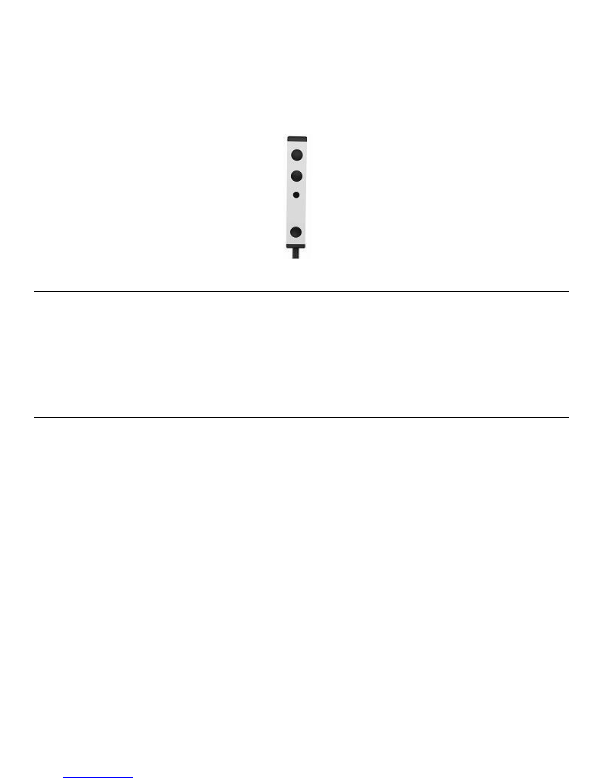
FEATURES
• Very small package, only 7/16" x 5/16" x 2-1/2".
• Easily mounts to any flat surface using the 3/8” x 1-3/4” double sided stick tape (included)
• Immunity to CFL (Compact Fluorescent Lights)
• Immunity to interference from LCD displays
• Improved response in direct sunlight
• Red talk-back LED tests system and indicates infrared reception.
• Includes 3-Terminal Block for easy extension of 7' ribbon cable.
Page 2
Page 2 Model 480-85
w
SPECIFICATIONS
• IR carrier input frequency reception range: 30 to 60 kHz.
• IR reception range: Up to 50 feet on axis (range depends on device being controlled and levels of IR or EM
interference).
• Reception angle: 55 degrees off axis with 50% range reduction.
• Power: 12 volts DC @ 20 mA.
• 781RG Power Supply (not included) powers up to 7 480-85's.
• Maximum current output: 100 mA peak.
• Cable requirements: See "INSTALLATION" below (un-shielded OK).
• Maximum cable length: 2000ft with 18 gauge.
NOTE: The 480-85 will not operate in 2-wire Phantom Power mode.
INSTALLATION
The 480-85 is intended to be wired to the input terminals of Xantech Connecting Blocks or other devices,
using the supplied 3-terminal block in the remote room location. A 3-conductor cable ((24 gauge up to 200'(61M),
22 gauge up to 600'(183M), 20 gauge up to 1000'(305M), 18 gauge up to 2000'(610M)), is run to the main room.
Connections are then made to a Xantech connecting block, power supply and emitters as shown in the illustration of a
typical basic system on the next page.
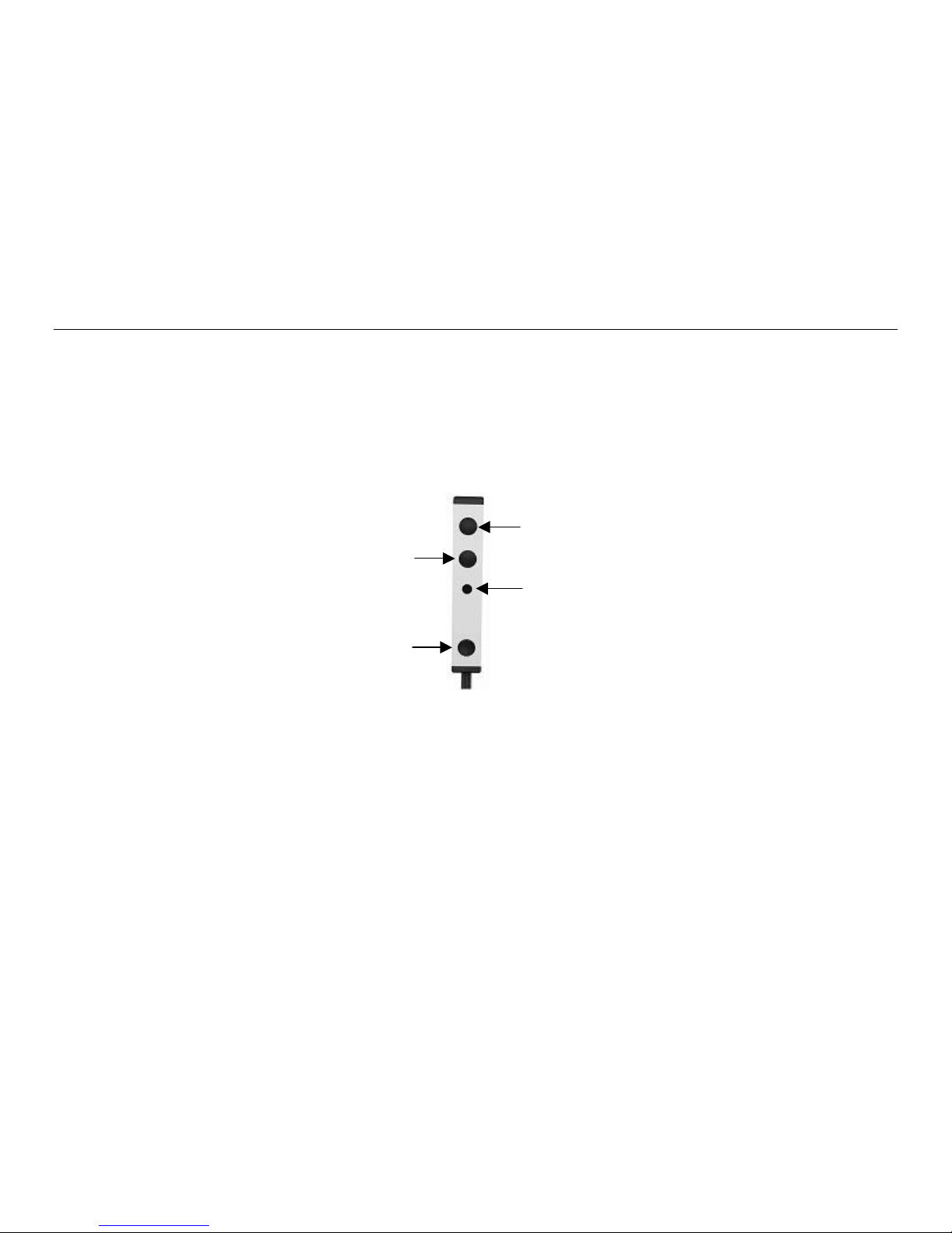
56kHz IR Receiver Window
38kHz IR Receiver Windo
Output Carrier Frequency
Adjustment Screw-Hole
Full CW=32kHz
Red TB LED Indicator
Full CW=56kHz
Figure 1 – 480-85 Features
MOUNTING
With its small size, the 480-85 can be mounted in many inconspicuous areas and can easily blend into its surroundings.
With the included double-sided strip of stick-tape, the 480-85 can easily be mounted directly on cabinet ledges, under
counters, and even directly on TV monitors or any other flat surface. The high sensitivity of these receivers also allows
placement behind speaker grilles and still receive IR commands from up to 30 feet away.
Note: If longer range is necessary, 3/8-inch holes must be drilled in the grille to allow unobstructed entry of the IR signal
to each of the IR receiver windows.
1. Remove one side of the double-stick tape from its protective layer and adhere to it the rear of the 480-85 Dinky
Link™
2. Make sure flat mounting surface is properly cleaned with isopropyl alcohol or other to remove any dirt or oils from
the surface.
3. Remove the remaining backing from the double-side stick tape on the rear of the 480-85 and place unit on
desired area on the flat surface you are mounting to.
4. Press evenly on the front of the 480-85 to assure it is properly adhered to the surface.
© 2005 Xantech Corporation
Page 3
Model 490-95 Page 3
APPLICATION WIRING
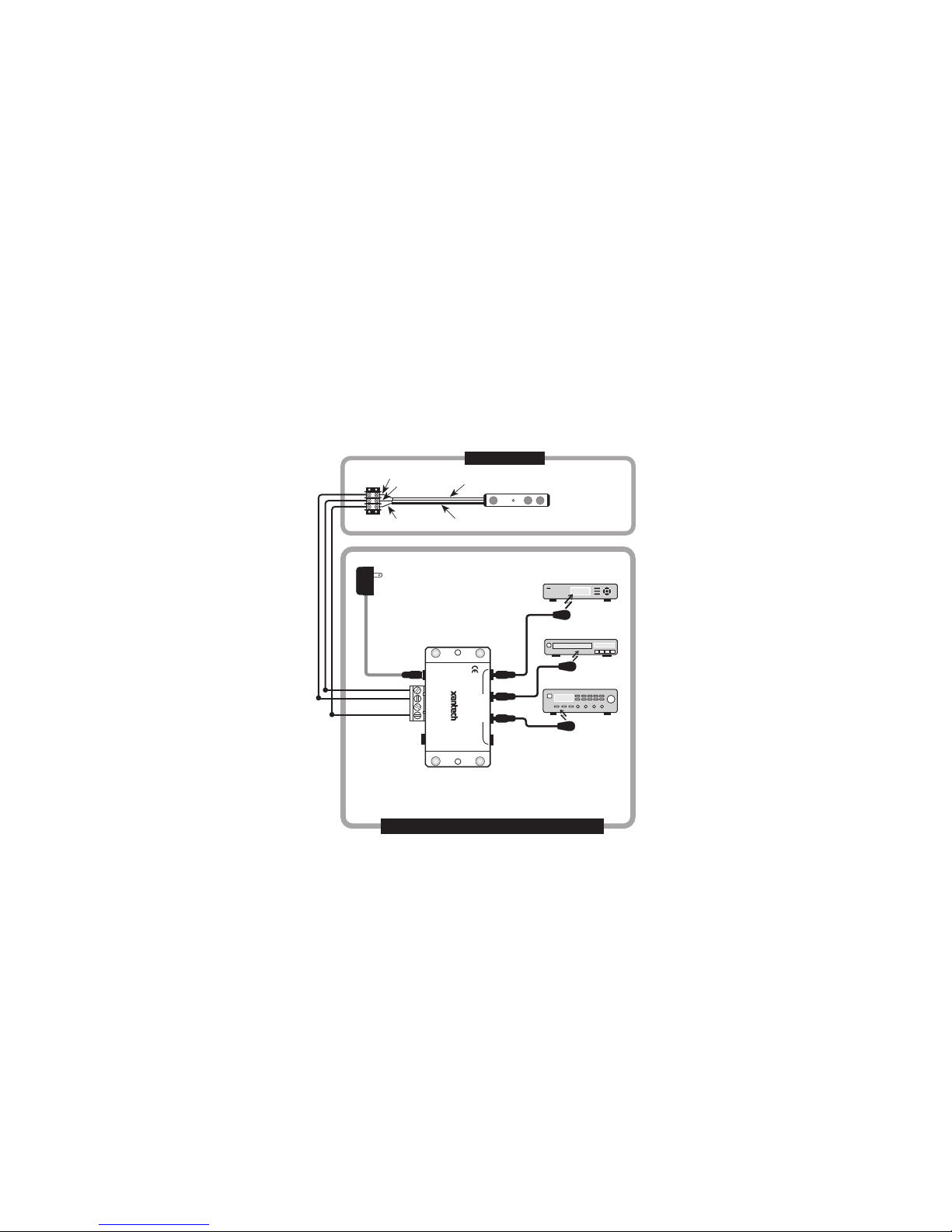
A typical system, with a 480-85, 781RG Power Supply and 283M Emitter plugged into a 789-44 Connecting Block, is
shown in Figure 2:
1. Run the 7 foot ribbon wire of the Dinky Link™ back to the home run location or where ever the Connecting Block
will be placed.
Note: If the connecting block must be placed at a distance greater than 7 feet, attach the tinned ends of the Dinky
Link™ cable to the terminals of the supplied 3-terminal strip (See Figure 2)
2. Connect the outer white-striped wire (IR Signal) of the Dinky Link’s ribbon cable to the terminal labeled IR IN on
the 789-44 Connecting Block.
3. Connect the middle wire (+12V) of the Dinky Link’s ribbon cable to the terminal labeled +12V on the 789-44
Connecting Block.
4. Connect the outer black wire (GND) of the Dinky Link’s ribbon cable to the terminal labeled GND on the 789-44
Connecting Block.
5. Plug in the Emitters 3.5mm mono mini plug such as any of the 282, 284, 283 and 286 series into the jacks labeled
EMITTERS on the 789-44 and affix the opposite end to the IR Sensor Window of the controlled equipment.
6. Connect the Plug in the 2.1mm Coaxial power plug of the 781RG Power Supply (not included) into the jack
labeled 12VDC on the 789-44 Connecting Block.
7. Plug the AC end of the 781RG power Supply into an ‘un-switched’ 120v AC Line outlet.
GND
+12V
IR OUT
REMOTE ROOM
3-Wire
Cable
White
Stripe
480-85
Dinky Link
IR Receiver
781-RG
Supply
MAIN ROOM 1, EQUIPMENT CABINET, ETC.
To 120 V AC
Power
(unswitched)
789-44
Connecting Block
12VDC
+12 VDC
GND
STATUS
IR IN
RCVR
IR
CONNECTING BLOCK
789-44
EMITTERS
®
Satellite Receiver
282M
Mouse Emitter
DVD
283M
Emitter
AV
Receiver
283M
Blink IR Emitter
Figure 2 - Typical System Layout using 480-85, 789-44, 781RG, and 283M Emitters
CAUTION: W ith any of these systems, be sure the 781-RG Power Supply is plugged into an un-switched AC outlet. This
maintains the 480 system in "stand-by" operation so that power-on commands can be sent to the controlled equipment.
ADJUSTING IR CARRIER FREQUENCY
The 480-85 is factory set to an IR carrier frequency of 38kHz. This will be correct for the majority of installations, however,
some manufacturer's components that you wish to control may use different carrier frequencies (such as the RCA DSS
Receivers, SA Cable boxes, etc which use carrier frequencies within the range of 52kHz - 56kHz). If such carrier
frequencies fall within the range of 32 kHz to 56 kHz, you can adjust the 480-85 to match them for best range
performance. The adjustment can be made through a small opening on the front of the unit. See Figure 1.
To adjust, proceed as follows:
1. First, try the 291-80 in the repeater system. If it controls all of the desired components with adequate range, do
not make any adjustments!
© 2004 Xantech Corporation
Page 4

Page 4 Model 480-85
2. If it does not work or has poor range (less than 15 feet), determine the IR carrier frequency of the product you
wish to control. Contact the manufacturer of the product, if necessary, to determine this frequency.
3. Using a small blade type screwdriv er (3/32" blade width max.), rotate the adjustment shaft slightly either
Clockwise for Carrier Frequencies less than 38kHz or Counter Clockwise for Carrier Frequencies greater than
38kHz.
4. If you have products in the same IR system that have different IR carrier frequencies, you will have to adjust the
480-85 to a midway position. For example, some products may operate at 38 kHz and others at 56 kHz. In this
case, set the adjustment to approximately ¾ CCW position.NOTE: Some products are more tolerant of
compromised frequency settings than others. You may have to "fine tune" the adjustment to "favor" the least
tolerant component for the best performance of all units in the system.
Table 1 - 480-85 Ribbon Wire Pin-Out
CABLE LEADS CIRCUIT ITEM
WHITE STRIPE IR OUT
MIDDLE WIRE +12V
OUTER BLACK GND
XANTECH CORPORATION
13100 Telfair Avenue, Sylmar CA 91342-3829
phone 818.362.0353 • fax 818.362.9506
Part No. 08901015 Rev X1 08-12-04
© 2005 Xantech Corporation
 Loading...