

Page 1
- 1 -
INSTALLATION INSTRUCTIONS
390-20
Shelf-Top, BLAST-IR Emitter
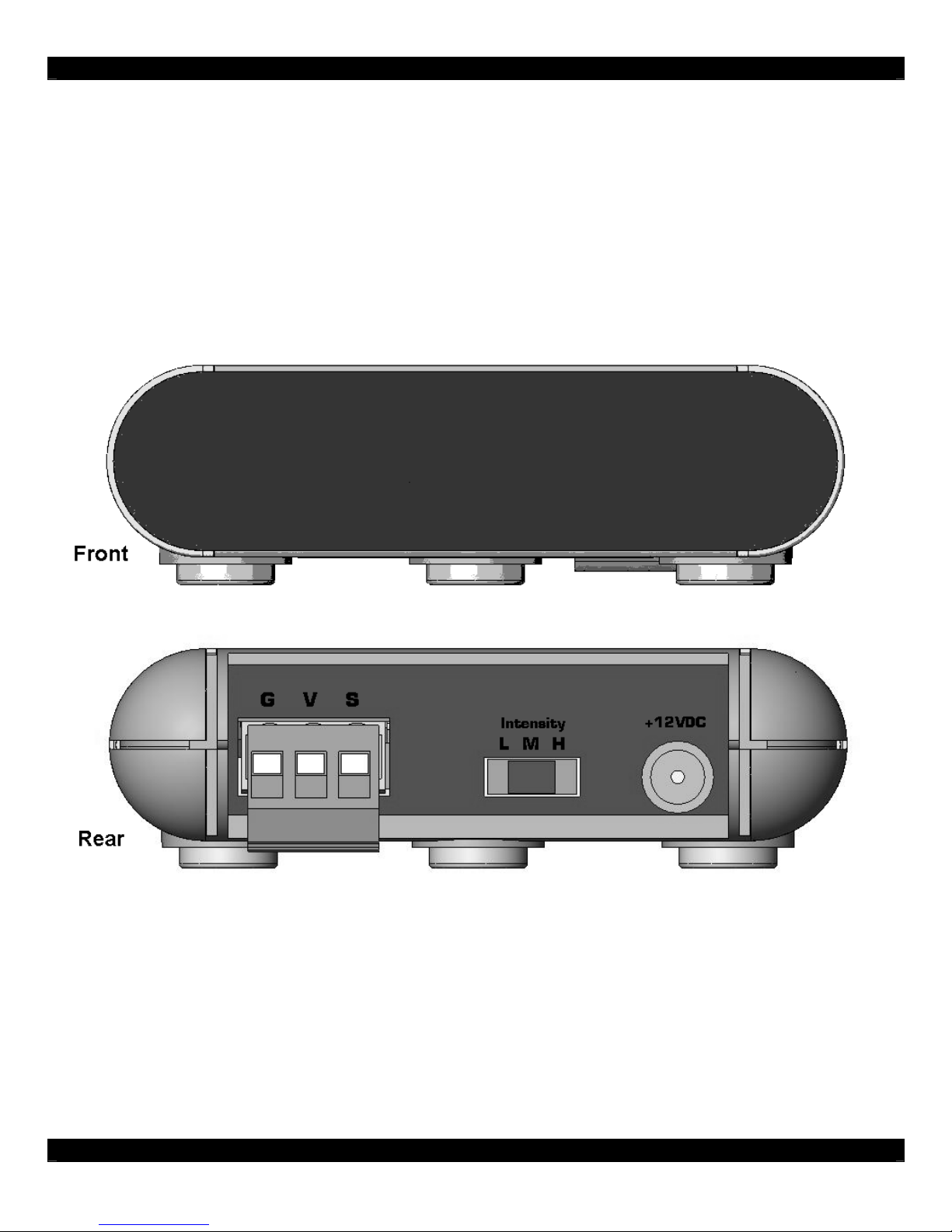
DESCRIPTION
The 390-20 BLAST-IR contains three high-intensity Infrared LEDs housed in a small shelf-top
assembly. The benefit of the 390-20 is that it can “flood” an enclosed area with an infrared signal. The
390-20 comes with a screw terminal plug that allows fast connection to any 3-wire IR receiver.
SPECIFICATIONS
+12VDC, 200mA.
Red IR Talk-back LED (internal).
3 Position Intensity Switch.
Dimensions: 3-1/4” W x 1” H x 2” D.
Screw Terminal Plug, (V = POWER, S = SIGNAL \ IR IN, G = GROUND).
Able to achieve a distance well over 30 feet.
Page 2
- 2 -
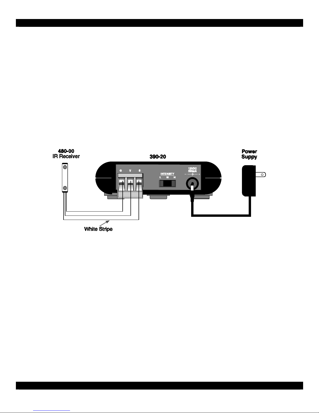
INSTALLATION - EXTERNAL IR RECEIVER (FIGURE 1 BELOW)
The easiest installation is to use the 390-20 with an external Xantech IR Receiver. Xantech IR
Receiver’s have 3 connections, +12VDC Power, IR OUT, and GROUND.
STEP 1: Connect the 3 wires from the Xantech IR Receiver to the 3-Pin Screw Terminal Plug.
- For Xantech IR receivers with a stripe conductor, this should be connected to “S” for IR IN. - -
- For Xantech IR receivers with colored wires, Red goes to “V” for +12VDC, White goes to “S”
for IR IN, and Black goes to “G” for Ground. Shown in Figure 1 below.
STEP 2: Plug the Screw Terminal Plug into the 390-20.
STEP 3: Select the desired Intensity level. It is suggested to use “H” for high level output.
STEP 4: Connect the power supply to the rear of the 390-20. Installation is complete.
FIGURE 1
INSTALLATION - CONNECTING BLOCK (FIGURE 2 NEXT PAGE)
In the event of multiple emitters connected to one IR receiver, using a connecting block, such as the
CB12 and 789-44, is the most convenient installation method.
STEP 1: Connect the included stripped mono-mini wire to the 3-Pin Screw Terminal Plug. The white
striped wire is connected to “S”. The other wire is connected to “G”.
STEP 2: Plug the Screw Terminal Plug into the 390-20.
STEP 3: Connect the emitters, the 390-20’s mono mini cable, and IR receivers to the connecting
block. See figure 2 on the next page.
STEP 4: Select the desired Intensity level. It is suggested to use “H” for high level output.
STEP 5: Connect the power supply to the rear of the connecting block. Installation is complete.
Page 3

- 3 -
While it is possible to make wired connections without a Xantech connecting block, it is not
recommended. The Xantech connecting block reduces installation time, helps to eliminate errors,
allows easy troubleshooting and permits easy system upgrades later, if needed.
FIGURE 2
Power Supply
It is recommended to use a +12Vdc, 200mA power supply.
Xantech’s 782-00 or 781RG power supply is acceptable for use with this product.
IR Compatibility
Due to various IR command structures, the 380-20 may not be compatible with certain brand name
components. It is highly recommended to test the 380-20 and all devices that it will control before final
installation.
Page 4

- 4 -
REPAIRS:
TECHNICAL SUPPORT PRE-AUTHORIZATION
Certain products require a Pre-Authorization from our Technical Support Department prior to a Return
Authorization (RA) being issued. Please call our Technical Support Department at 800 843-5465
Extension 301 if you have a problem with any of the following products: Any MRC Controller or
Keypad, SmartPad LCD (any model), ZPR68 (any version), 49090, 78090, any PA series amplifier,
PM110, LM110, WPK (any version), DD4, Gate KeepIR (any version), RT8, RT16, RAT1, URC2 (any
version), MAC1, IRS232, IRS232A, RS232IR, RS2321X8, Xtralink-IP 172 series, 590-10, 710-00,
730-00, XDT, PMX/LMX , and BXAUDIO. Technical Support will transfer your call to the Sales
Department to complete the ATR process.
LIMITED WARRANTY
Xantech warrants its products to be free of defects in materials or workmanship. This warranty
extends for one year from the date of purchase by the consumer. Any products returned freight
prepaid to Xantech and found to be defective by Xantech within the warranty period will be repaired
or replaced, at Xantech's option, at no charge. Xantech will not be responsible for the actual cost of
installation or removal of the product, nor for any incidental or consequential damages. Some states
do not allow the exclusion or limitation of incidental or consequential damages so the above limitation
or exclusion may not apply to you. This warranty gives you specific legal rights. You may have
additional rights which vary from state to state.
XANTECH CORPORATION
13100 Telfair Avenue
Sylmar, CA 91342
Phone 818-362-0353 Fax 818-362-9506
www.xantech.com
Part No. 08905059 Rev X5 12-12-05
© 2005 Xantech Corporation
 Loading...