

Page 1

INSTALLATION INSTRUCTIONS
284-10
DUAL MINI EMITTER
DESCRIPTION
• The 284-10 is a dual emitter assembly. The emitters are wired in series with each other and each contain
a small infrared LED housed in a miniature, black appearing, injection molded plastic shell.
• They emit control signals in the form of invisible infra-red (IR) light when activated by IR commands sent
to them by IR receivers or other Xantech controllers.
• They are designed to be installed directly on the IR sensor window of each controlled device.
(+)
(–)
3.5mm mono
mini plug
NOTE: White striped side is (–) negative
(on 284-10 only).
Model 284-10 Dual IR Emitter
7 FT 3 FT
INSTALLATION
ATTACHING THE EMITTERS TO IR SENSOR WINDOWS
• Each emitter has a clear adhesive layer on the bottom flat surface of the shell. The rounded side faces
the user and emits invisible IR light as well as the flat surface when a command is sent.
• Simply peel off the protective cover and affix the emitter to the center of the IR sensor window on the
controlled component's front panel.
• In some cases it may be difficult to find the location of the IR sensor on the component. Consult the owner's
manual of such units, or the manufacturer, for the exact IR window location.
• Double-sided adhesive tape is included. If you move
the emitter to a different component, use a piece of
this tape to replace the current adhesive layer, if
needed.
• The shell, though black in appearance, is transparent
to infrared light, allowing commands from a handheld
remote control to pass through the shell. This permits
direct control of the equipment from a handheld
remote as well as from the 284-10.
CONNECTING THE EMITTERS
• Simply insert the mono mini plug of the 284-10 assembly into the "EMITTERS" or "OUT" jacks on any of
the Xantech Connecting Blocks or Controllers.
CAUTION:
Series Amplified Connecting Blocks.
DO NOT plug emitters into the IN/OUT or HIGH OUT jacks on the 790-00 or the 791
To do so will destroy the emitters!
3/4"
5/16"
Emitter Shell Clear adhesive
Rounded
Side
layer.
(Replace, when necessary,
with a short piece of twosided adhesive tape
supplied).
Flat surface
Emitters & Blasters
1
Page 2
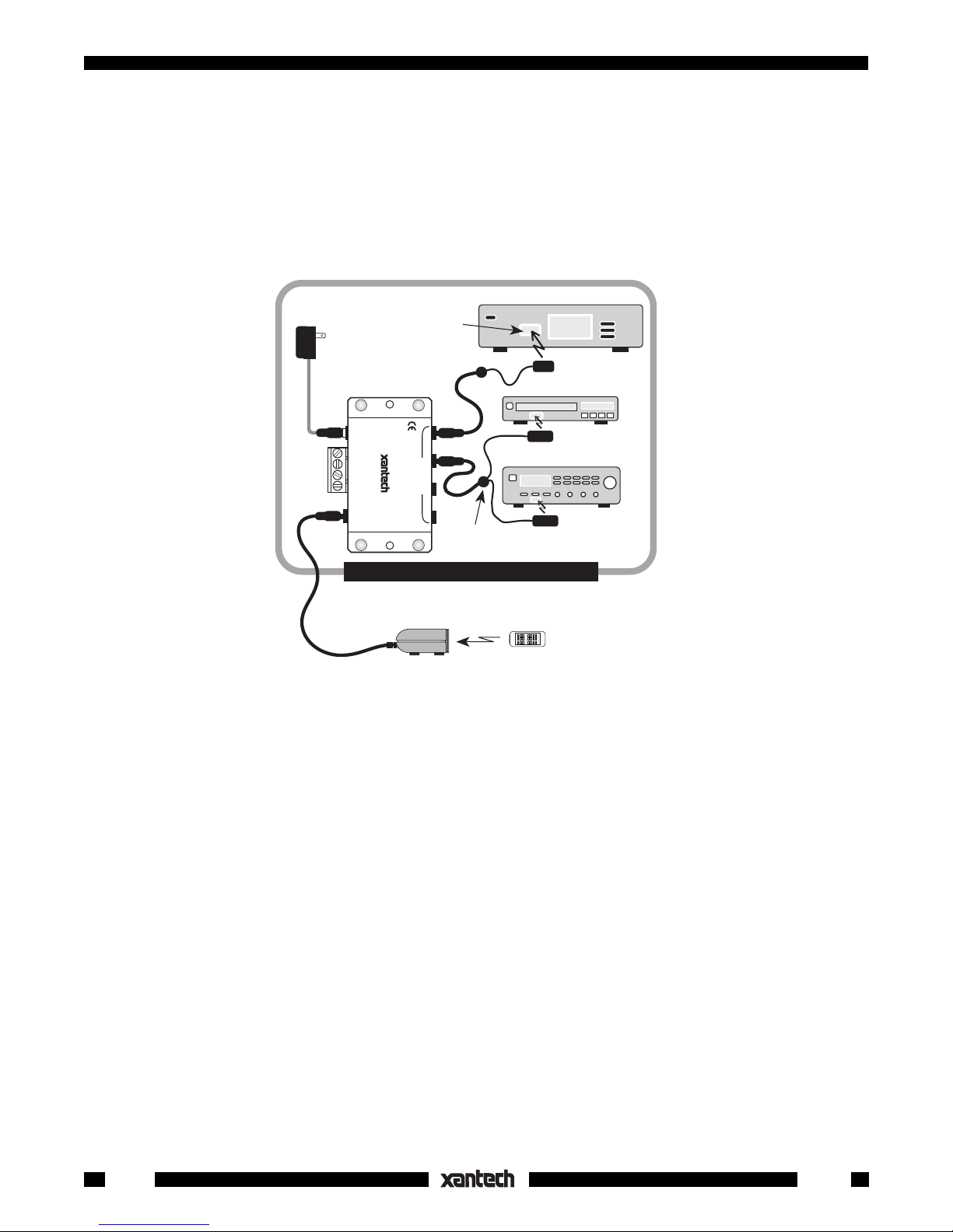
• The diagram below illustrates a typical basic IR controlled system using the 284-10 emitters (as well as
a single 282-00 emitter).
• The 284-10 is designed to control two components. If only one is to be controlled, hide the extra emitter
behind the equipment. It may be used in the future if an extra component is added.
781RG
Power Supply
To 120 V AC
(unswitched)
789-44
Connecting Block
12VDC
CONNECTING BLOCK
+12 VDC
GND
STATU S
IR IN
RCVR
IR
789-44
®
IR Sensor
Window
EMITTERS
284-10
Satellite Receiver
282-00
VCR
AV Receiver
Dual Emitter Assembly
Emitter
EQUIPMENT CABINET, CLOSET, ETC.
291-10
IR Receiver
• DO NOT CUT the extra emitter wire in an attempt to remove it. The two emitters are wired in series. Cutting
Hand Held
Remote
Amplifiers & Preamplifiers
or removing one emitter will prevent the other from working.
• CAUTION: If you cut off the plug for wired applications, be aware that the white striped side of the lead
is negative (--) for the 284-10 only. On all other Xantech emitters, the white stripe is positive.
2
3-24-00
284-10
 Loading...