

Page 1
INSTALLATION INSTRUCTIONS
283M
BLINK-IR™ MOUSE EMITTER
DESCRIPTION
The 283M Blink-IR Mouse Emitter contains a small Infrared LED housed in a miniature, mouse shaped,
black appearing, injection molded plastic shell. Unlike other emitters, the 283M emits visible red light in
addition to IR (infrared) control signals when activated by IR commands sent to it by IR receivers or other
Xantech controllers. The 283M is designed to be installed directly on the IR sensor window of the controlled
device.
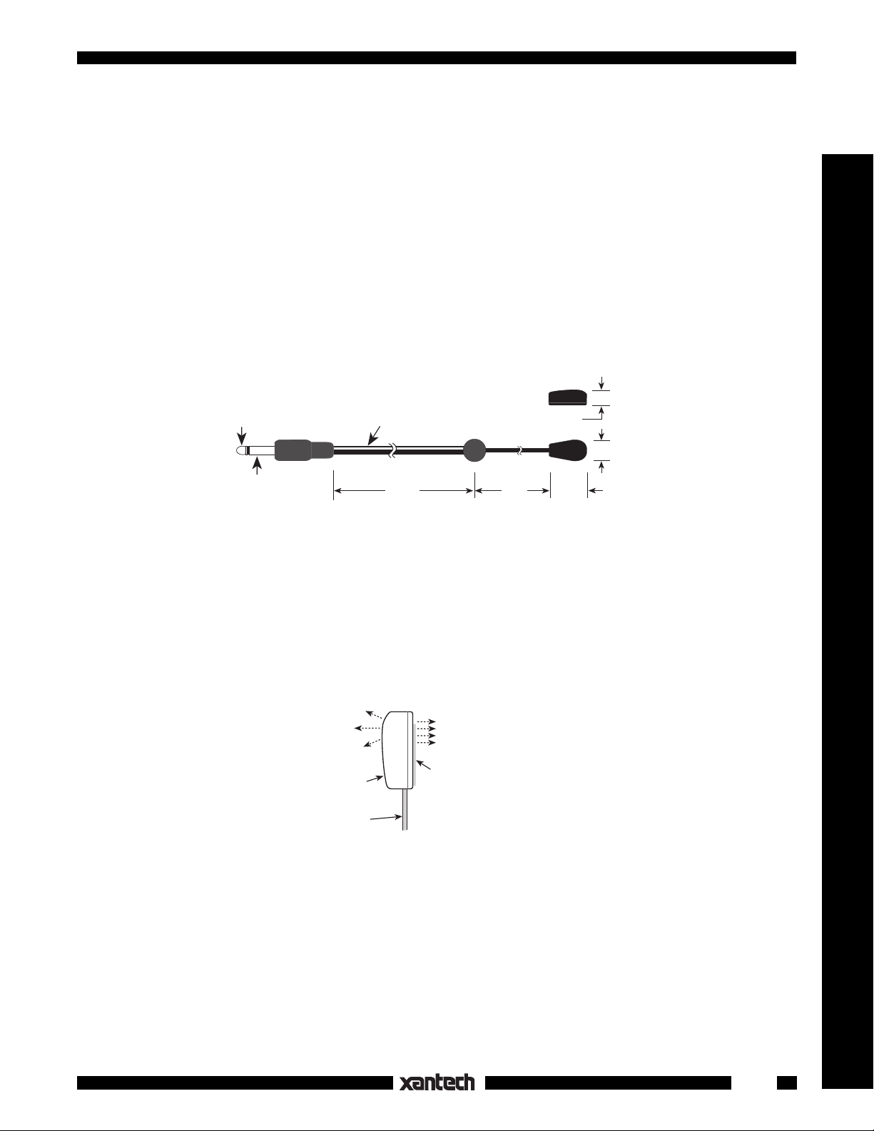
Blink-IR™ Mouse Emitter Assembly
3.5mm mono
(+)
mini plug
(–)
Fig. 1
INSTALLATION
ATTACHING THE EMITTERS TO IR SENSOR WINDOWS
• Each emitter has a clear adhesive layer on the bottom flat surface of the shell. The rounded side faces
the user and emits visible red light when a command is sent (Fig. 2).
• Simply peel off the adhesive cover and affix the emitter to the center of the IR sensor window on the
controlled component's front panel.
Model 283M
NOTE: White striped
side is positive (+)
7 FT 3 FT
Side View
1/4"
Top View
5/16"
9/16"
Emitters & Blasters
Fig. 2
IR & Red
Light
Output
Emitter
Shell
Mini-wire
lead
IR & Red
Light Output
(Component Side)
Clear adhesive
layer.
(Replace, if necessary,
with a short piece of the
2-sided tape supplied).
• In some cases it may be difficult to find the location of the IR sensor on the component. Consult the owner's
manual of the unit, or the manufacturer, for the exact IR sensor window location.
• Double-sided adhesive tape is included. If you move the emitter to a different component, use this tape
to replace the current adhesive layer for best adhesion.
• The shell, though dark in appearance, is transparent to infrared light, allowing commands from a handheld
remote control to pass through it. This permits direct control of the equipment from a handheld remote as
well as from the 283M.
1
Page 2

BLACK (IR OPAQUE) MOUSE SHIELD
• An optional shield, available from Xantech as model MS-1, fits over the 283M and the sensor window
(Fig. 3) of the controlled component. It prevents unwanted external IR signals from passing through or
leaking past it.
• Use the MS-1 when you want the equipment to respond
only to the 283M, such as in zone controlled
systems.
• Install it according to the instructions that come with the MS-1.
MS-1
Mouse Emitter Shield
Fig. 3
Side ViewTop View
Adhesive Layer
283M
Emitter
Controlled Component
MS-1
and 283M installed
over IR sensor window.
CONNECTING THE EMITTERS
• Simply insert the mono mini plug of the 283M emitter into the "EMITTERS" or "OUT" jacks on any of the
Xantech Connecting Blocks or Controllers.
• CAUTION:
Connecting Blocks.
DO NOT plug emitters into the IN/OUT or HIGH OUT jacks on the 790-00 and 791-44
To do so will destroy the emitters!
• Fig. 4 illustrates a typical basic system using 283M emitters.
• The 283M visible mouse emitter will also indicate the presence of stray IR or RF interference by randomly
blinking when no IR control signal is being sent. Reposition the IR receiver or the interfering source to
eliminate or reduce the random blinking. The more the random blinking is reduced, the better the system
will function.
781RG
Power Supply
To 120 V AC
(unswitched)
789-44
Connecting Block
12VDC
CONNECTING BLOCK
+12 VDC
789-44
GND
STATU S
IR IN
®
RCVR
IR
IR Sensor
Window
EMITTERS
Satellite Receiver
283M
VCR
283M
AV Receiver
283M
Mouse Emitter
Emitter
Emitter
Blink-IR™
EQUIPMENT CABINET, CLOSET, ETC.
291-00
IR Receiver
Fig. 4
2
Hand Held
Remote
5-18-00
283M
 Loading...