

Page 1
MODEL
282X
‘NAKED’ [No Shell] EMITTER
INSTALLATION INSTRUCTIONS
DESCRIPTION
The 282X is Xantech’s Mouse Emitter without the Mouse! That’s
right, an emitter without the shell! This emitter is for those jobs
where you need that clean & natural look with no emitter stuck to
the front of the device and no wire hanging above or below the
DVD Pl ayer, Home Theater Receiver or other.
This emitter can be placed ins ide the device attached near the units
internal IR Sensor with the emitter wire dressed neatly out the rear
for a perfectly clean IR Control System.
Model 282X
‘Naked’ [No Sh ell] Emitter
Fig. 1
INSTALLATION
ATTACHING THE EMIITER TO THE INSIDE OF THE IR
CONTROLLED DEVICE
• Disconnect the IR controlled device from the AC power
source.
• Remove the top cover of the device.
Note: Consult the device manufacturer’s instruction
manual for possible Warranty issues.
• Locate the devices internal IR Sensor along the front
panel.
• In cases where it is difficult to find the IR sensor, consult
the device’s owner’s manual or locate the IR sensor via
the front panel, using a flashlight to see through the front
window. If all else fails, simply place the 282X emitter in
different locations and see where the most reliable control
is achieved.
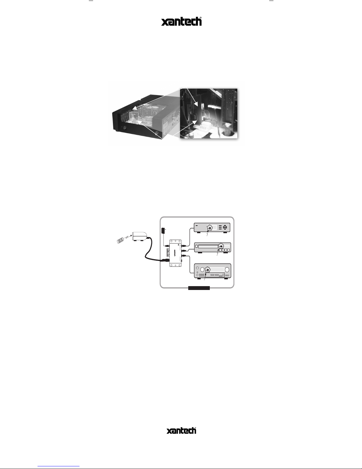
• Adhere the 282X emitter close to the sensor (or best
location) using hot glue or other adhesive. See Figure 2.
KEEP HOT GLUE OFF OF EMITTER LENS.
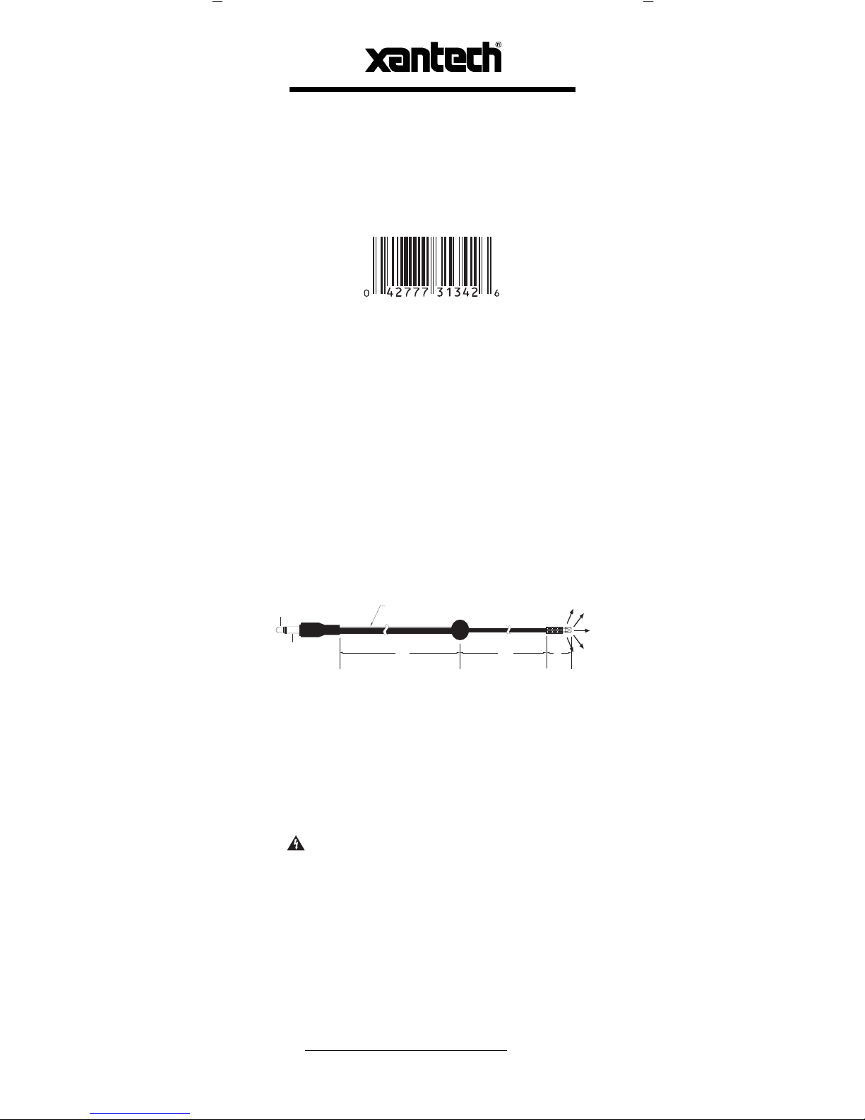
3.5MM MONO
MINI PLUG
(+)
(-)
NOTE: WHITE STRIPED SIDE IS POSITIVE
TOP VIEW
5/8
3 FT
7 FT
Page 2
Corporation
13100 T elfair Ave., Sylmar CA 91342 • www.xantech.com
08901674 Rev. A
Note: Be sure to dress the emitter wire away from any moving
parts within the device. It might be necessary to ‘tack’ the 282X
wire down in multiple locations to be sure.
In some cases it might be easiest to ‘tack’ the emitter to a
location on the inside of the devices top cover that controls the
device reliably. This will keep the 282X wiring away from any
moving parts and the devices inner circuitry.
CONNECTING THE EMITTERS
• Simply insert the mono mini plug of the 282X into the
“EMITTERS” or “OUT” jacks on any of the Xantech
Connecting Blocks or Controllers.
• CAUTION: Do not plug emitters into the IN/OUT or HIGH
OUT jacks on the 791-44 or 790-00 Connecting Blocks. To do
so will destroy the emitter!
• Fig. 3 below illustrates a typical basic system using the
282X Emitter.
LIMITED WARRANTY
Xantech® warrants its products to be free of defects in materials or workmanship. This
warranty extends for one year from the date of purchase by the original consumer. Any
products returned to Xantech and found to be defective by Xantech within the warranty period
will be repaired or replaced, at Xantech’s option, at no charge. Xantech will not be responsible
for the actual cost of installation or removal of the product, nor for any incidental or
consequential damages. Some states do not allow the exclusion or limitation of incidental or
consequential damages, so the above limitation may not apply to you. This warranty gives you
specific legal rights. You may have additional legal rights that vary from state to state.
Component IR Sensor Window
Fig. 3: 282X Basic System Diagram
Emitters displayed looking ‘through’ devices front panel.
282X
The Naked Emitter
To 120 V AC
(unswitched)
781RG
Power Supply
789-44
Connecting Block
282X
Emitter
282X
Emitter
Equipment Rack
Hand Held
Remote
291-90
Hidden Link
Plasma-Friendly
IR Receiver
12VDC
+12 VDC
GND
STATUS
IR IN
EMITTERS
IR
RCVR
789-44
CONNECTING BLOCK
®
Satellite Receiver
AV
Receiver
VCR
Fig. 2: Emitter Placement
 Loading...