

Page 1
INSTALLATION INSTRUCTIONS
282M
MOUSE EMITTER
DESCRIPTION
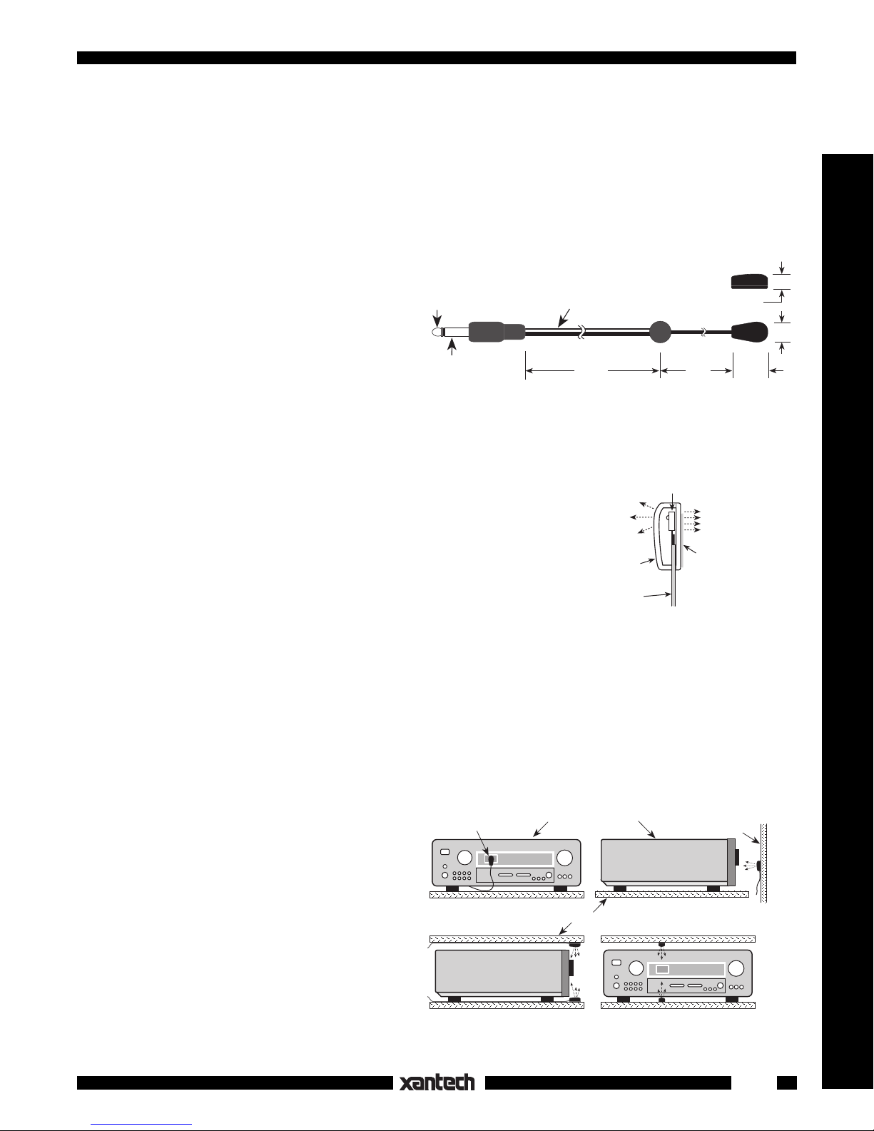
The 282M Mouse Emitter contains a tiny infrared
LED housed in a miniature, mouse shaped, black
3.5mm mono
appearing, injection molded plastic shell. It emits
(+)
mini plug
IR (infrared) control signals sent to it by IR receivers or other Xantech controllers. The 282M can
be installed directly on the IR sensor window of
(–)
the controlled device or other suitable location.
Refer to Fig. 3.
INSTALLATION
ATTACHING THE EMITTERS TO IR SENSOR WINDOWS
• Each emitter has a clear adhesive layer on the bottom flat surface of
the shell (Fig. 2).
• Simply peel off the adhesive protective cover and stick the emitter to
the center of the IR sensor window on the controlled component's front
panel. (See Fig. 3a). If you remove the emitter for any reason, it may
be necessary to replace the adhesive with a fresh piece of the 2-sided
tape (supplied) to restore best adhesion.
• In some cases it may be difficult to find the location of the IR sensor on
the component. Consult the owner's manual of the unit, or the manufacturer, for the exact IR window location.
• Since the Emitter Shell is transparent to infrared, it allows you to control the component from a hand-held
remote as well as with the 282M.
ATTACHING THE EMITTERS TO OTHER LOCATIONS
• The high output from the curved top side of the emitter (Fig. 2) permits control from as much as 3 feet away
when on the axis of the IR sensor window of the component.
* This allows placement on surfaces just be-
low, above or in front of the controlled components for a more pleasing aesthetic appear-
IR Sensor
Window
IR Controlled Components
ance.
• Choose a location on a cabinet shelf, door,
etc., as shown in Figs. 3b, c and d. Be sure
the edge of the component does not block the
IR signal (Figs. 3c and d).
Fig. 3a 282M attached directly
to IR sensor window
CAUTION: Cabinet door locations (Fig. 3b)
will usually result in interruption of the IR
control signals to the components when the
door is open.
Fig. 3c & d 282M attached to shelf directly below
Model 282M
Mouse Emitter Assembly
NOTE: White striped
side is positive (+)
7 FT 3 FT
Fig. 1
High
Output
Side
Fig. 1
Emitter
Shell
Mini-wire
lead
Fig. 3b 282M attached to front cabinet door
Shelves
or above IR sensor window
directly opposite IR sensor window
Internal
IR Emitter
Fig. 2
Side View
1/4"
Top View
9/16"
Low
Output
Side
Clear adhesive
layer.
(Replace, if necessary,
with a short piece of the
2-sided tape supplied).
Cabinet Door
5/16"
Emitters & Blasters
Fig. 3 Emitter attachment locations
1
Page 2
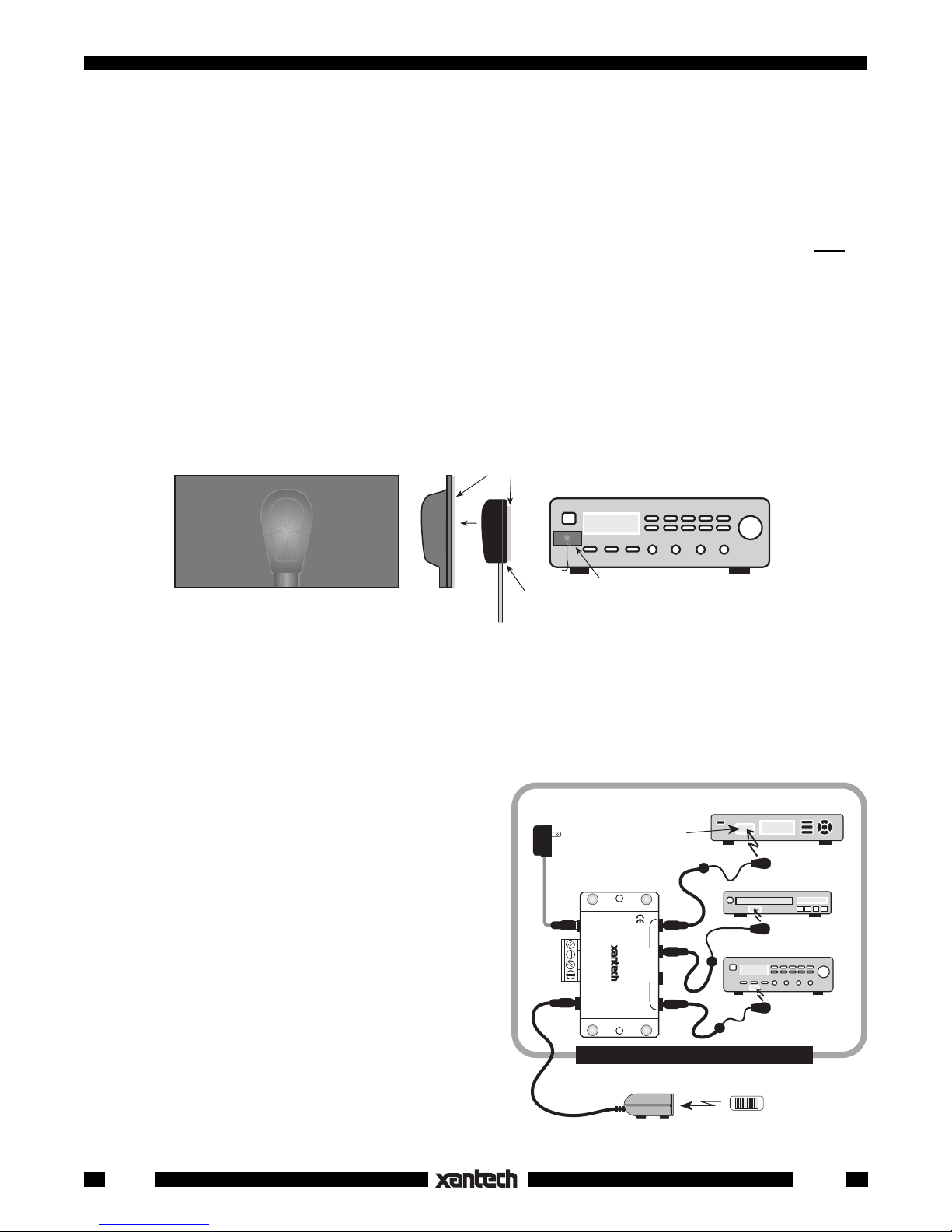
BLACK (IR OPAQUE) MOUSE SHIELD.
• An optional shield, available from Xantech as model MS-1, fits over both the 282M mouse emitter shell
and the sensor window of the controlled component. It prevents unwanted external IR signals from
passing through or leaking past it.
• The MS-1 also prevents IR from the 282M from radiating backward into the IR sensors of other
components.
• It is especially useful for zone controlled applications where you want the equipment controlled
only by
the 282M fastened over the component IR sensors.
Install as follows:
1. Before removing the adhesive covers from the shield or the emitter, fit them together and accurately
position them over the IR sensor window of the component.
2. Neatly trim the shield (if needed) being sure that it overlaps the extremities of the equipment’s IR
sensor window.
3. Remove adhesive covers from the shield and the emitter and stick them onto the IR sensor window.
MS-1
Mouse Emitter Shield
Adhesive Layer
Controlled Component
Side ViewTop View
Fig. 4
CONNECTING THE EMITTERS
• Simply insert the mono mini plug of the 282M
emitters into the "EMITTERS" or "OUT" jacks on
any of the Xantech Connecting Blocks or Controllers.
• CAUTION:
DO NOT plug them into the IN/OUT
or HIGH OUT jacks on the 791-44 and 790-00
Connecting Blocks.
To do so will destroy the
emitters!
• Fig. 5 illustrates a typical basic system using the
282M emitters.
282M
Emitter
MS-1 and 282M installed
over IR sensor. Trim edges
of MS-1 as needed (see text).
781RG
Power Supply
To 120 V AC
(Unswitched)
Connecting Block
12VDC
+12 VDC
GND
STATUS
IR IN
RCVR
IR
IR Sensor
Window
789-44
CONNECTING BLOCK
789-44
EMITTERS
®
Satellite Receiver
282M
VCR
282M
AV Receiver
282M
Emitter
Emitter
Emitter
2
EQUIPMENT CABINET, CLOSET, ETC.
291-00
IR Receiver
Fig. 5
Hand Held
Remote
282M
3-13-00
 Loading...