

Page 1
INSTALLATION INSTRUCTIONS
172-77
XTRA LINK® 2
REMOTE CONTROL EXTENSION SYSTEM
The Xtra Link 2 system provides full remote control operation of a satellite receiver, cable box or VCR from
a second room by sharing the coaxial cable connecting your video equipment to this second room’s TV.
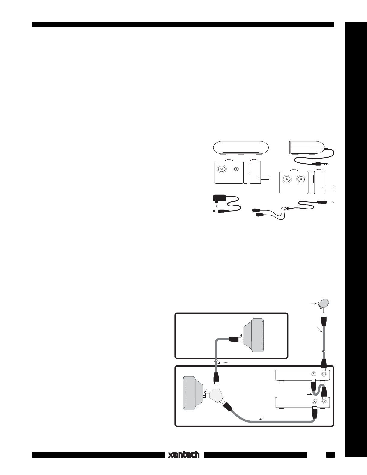
The 172-77 Xtra Link consists of the following supplied parts:
1. An infrared Receiver, Model 291-00. It is placed at the
remote room location to receive IR signals from the
handheld remote controller.
Front View Side View
2. One INJ77 Injector. This unit, located in the Remote
Room, injects the remote control signal into the roomto-room coaxial cable (along with the TV signal) and
passes it to the CPL77 Coupler in the Main room. It
also provides quick connection of the 291-00 IR Receiver and 781C-77 Power Supply cables.
IR RECEIVER
ANT INPUT
INJ77 INJECTOR
781C-77
Power Supply
+12 V
3. One CPL77 Coupler. Located in the Main Room, this
Coupler extracts the remote control signal from the
coaxial cable and passes it to the emitters that control
your source equipment. In addition, the CPL77 contains a 2-way RF splitter so that the TV signal can be
172-77 Xtra Link 2 System Parts
fed to a local TV.
4. One Dual IR Emitter, Model 284M. The emitters on this device allow control of two infrared remote
controlled audio/video components.
5. A 781C-77 Power supply. This plugs into an unswitched 220-240 VAC outlet to provide power to the
291-00 IR Receiver.
291-00 IR Receiver
TO TV
SIDE VIEW
EMITTER
LOCAL TV
CPL77 COUPLER
REMOTE TV
284M
Dual Mouse Emitter
SAT/VCR
SIDE VIEW
IR Receivers
CONNECTIONS
The Xtra Link system uses the coaxial cable that
carries the TV RF signal from the source equipment in the main room to the remote room, to
send the IR control signals back to the source
equipment. The coaxial cable may be up to one
mile in length.
If you already have a coaxial cable connecting
your video equipment with a remote room, your
current hookup should be similar to Fig. 1. If it
isn't, run a single length of RG59 or preferably
RG6 cable from the Main Room to the Remote
Room.
NOTE: If RF amplifier(s) are used anywhere in
the line of coaxial cable between the CPL77
Coupler and the INJ77 Injector, you must use a
Xantech BYPASS77 KIT to route the IR commands around the amplifier(s).
REMOTE ROOM
1ST
RF IN
TV
MAIN ROOM
RF IN
Room-to-Room Coaxial Cable
RF SPLITTER
2-Way
2ND
TV
Coaxial Cable
Fig. 1 Basic System Without Xtra Link
Satellite Dish
Coaxial Cable
SATELLITE RECEIVER
(Back Panel)
Coaxial Cable
VCR
(Back Panel)
OUT TO TV
RF INOUT TO TV
RF IN
1
Page 2
When using more than one Xtra Link for more rooms, be sure the RF splitters you use are DC passing types,
such as Xantech part number 04027500 (2-way). Refer to Fig. 3.
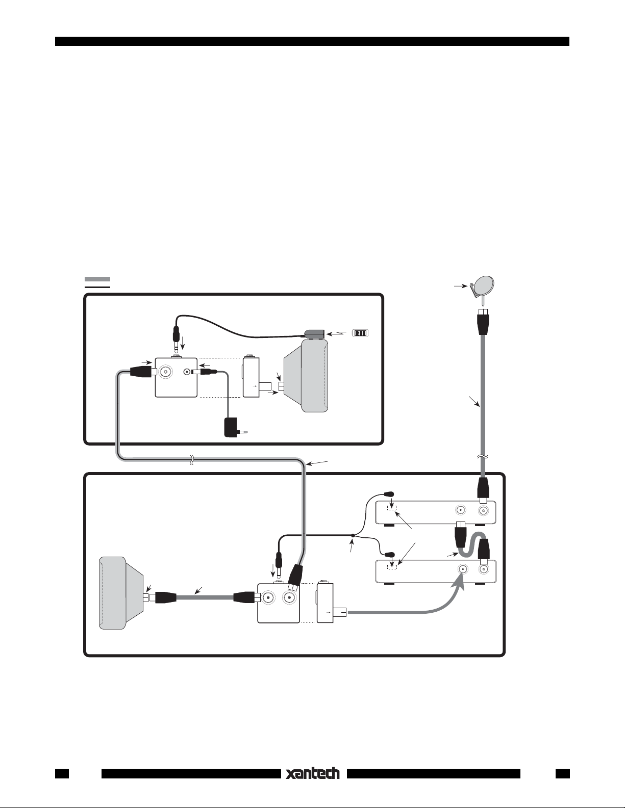
INSTALLING THE 291-00 IR RECEIVER
Insert the cable mini plug attached to the 291-00 into the jack marked "IR RECEIVER" on the INJ77 Injector.
Refer to Fig. 2.
Plug the 781C-77 Power Supply cord into the jack marked "+12 V" on the INJ77 Injector. Plug the 781C77 into a 220 VAC unswitched outlet after you have made all other connections.
Position the 291-00 IR Receiver so that the infrared beam from the handheld remote control has a direct
view to the front of the unit (within 20 feet).
INSTALLING THE INJ77 INJECTOR
Insert the "TO TV" plug on the back of the INJ77 Injector into "RF IN" on the TV in the Remote Room.
Connect the room-to-room cable to "ANT INPUT" on the INJ77 Injector.
TV SIGNAL PATH
IR REMOTE CONTROL PATH
REMOTE
ROOM
IR RECEIVER
ANT INPUT
INJ77 INJECTOR
Front View
INJ77 INJECTOR
(included)
Power Supply (included)
1ST
RF IN
TV
MAIN ROOM
+12 V
781C77
Coaxial Cable
(not included)
RF IN
TO TV
Side View
To 220 V AC
(unswitched)
EMITTER
LOCAL TV
REMOTE
TV
CPL77 COUPLER
Front View Side View
CPL77 COUPLER
(included)
291-00
IR RECEIVER
(Included)
2ND
TV
Room-to-Room Coaxial Cable
(not included)
Place emitters on
the IR sensor
window on front
panel of each
controlled unit.
284M
Dual Mouse
Emitter Assembly
(included)
SAT/VCR
Hand Held
Remote
Satellite Dish
Emitter
SATELLITE
RECEIVER
(Back Panel)
IR Sensor Windows
(Front Panel)
Emitter
Coaxial Cable
(Back Panel)
(Not included)
VCR
Coaxial Cable
(not included)
OUT TO TV
RF INOUT TO TV
RF IN
Fig. 2 Basic Xtra Link Hookup
INSTALLING THE CPL77 COUPLER
Insert the "SAT/VCR" plug on the back of the CPL77 Coupler into "OUT TO TV" on VCR in the Main Room.
Connect the room-to-room cable to "REMOTE/TV" on the CPL77 Coupler.
Make the remaining connections from the CPL77 Coupler to the TV, the VCR to the satellite receiver, etc.,
as shown in Fig. 2.
2
172-77
Page 3

INSTALLING THE XTRA LINK 284M DUAL IR EMITTER
Plug the 284M Dual IR Emitter into the jack marked "EMITTER" on the CPL77 Coupler in the Main Room.
The 284M emitters should be installed directly to the infrared sensor "window" on the front panel of the
satellite receiver, VCR, cable box, etc. Simply remove the paper backing exposing the adhesive surface
of each emitter and apply them to the center of the sensor window.
NOTE: Although the 284M appears dark to the eye, it is transparent to infrared. Positioning the 284M
directly over the infrared window(s) of the component(s) will not block direct IR control from a handheld
remote.
OPERATION
To use the Xtra Link Remote Control Extension System, simply point your handheld remote control(s) at
the 291-00 IR Receiver and press the desired button. A red LED on the front of the 291-00 will indicate the
reception of your infrared command.
NOTE: The maximum usable distance between your IR remote and the 291-00 Receiver will vary for each
remote and might be shorter than when directly used in the room containing the satellite receiver or other
IR controlled devices.
ADVANCED MULTIROOM HOOKUP
Fig. 3 shows an advanced system using two Xtra Links in a multiroom installation. Except for the addition
of a 2-way DC passing RF splitter (such as Xantech part no. 04027500), the connections are essentially
the same.
Satellite Dish
TV SIGNAL PATH
IR REMOTE CONTROL PATH
IR Receivers
REMOTE
ROOM
ANT INPUT
INJ77
Power Supply (included)
Room-to-Room
Coaxial Cable
(not included)
1ST
TV
IR RECEIVER
+12 V
INJ77 INJECTOR
Front View Side View
INJECTOR
(included)
781C77
RF IN
TO TV
To 220 V AC
(unswitched)
RF SPLITTER
2-Way DC Passing
(Xantech # 04027500,
not Included)
Coaxial Cable
MAIN ROOM
IR RECEIVER
RF
IN
(not included)
291-00
(included)
2ND
TV
Coaxial Cable
(not included)
REMOTE
ROOM
Hand Held
Remote
Place emitters on
the IR sensor
window on front
panel of each
controlled unit.
EMITTER
LOCAL TV
REMOTE
TV
CPL77 COUPLER
Front View Side View
CPL77 COUPLER
(included)
IR RECEIVER
+12 V
ANT INPUT
INJ77 INJECTOR
Front View Side View
INJ77
INJECTOR
(included)
Power Supply (included)
Emitter Assembly
781C77
Room-to-Room Coaxial Cable
(not included)
284M
Dual Mouse
(included)
SAT/VCR
RF
IN
TO TV
To 220 V AC
(unswitched)
Emitter
SATELLITE
RECEIVER
(Back Panel)
IR Sensor Windows
(Front Panel)
Emitter
(Back Panel)
IR RECEIVER
Coaxial Cable
(not included)
Coaxial Cable
(not included)
VCR
291-00
(included)
3RD
TV
OUT TO TV
Hand Held
Remote
RF INOUT TO TV
RF IN
172-77
Fig. 3 Advanced Multiroom Hookup
3
Page 4

HOW TO AVOID PROBLEMS
In rare cases, the 291-00 IR Receiver may have to be moved to a different location if the unit is picking up
interference. This interference may, in severe cases, prevent the system from working.
Common examples of interference are:
• RF radiation from the TV set on which the 291-00 IR Receiver may have been placed.
• Direct or reflected sunlight.
• Fluorescent, Compact Fluorescent, Neon, Neon Art, Halogen lights or light dimmers.
• Infrared security systems.
You can confirm the source of the interference by temporarily turning off the remote room TV set, isolating
the 291-00 Receiver from all sunlight and turning off all lights, light dimmers and Infrared security systems.
Then check to see if the 291-00 operates the satellite receiver or other components.
If the 291-00 still does not work, reposition the 284M Emitter(s). It may not be located directly over the
component’s infrared receiving "window". Consult the owner's manual of the unit or the manufacturer for
the exact location of the infrared "window".
IMPORTANT: For installations involving more than two remote rooms, use the services of a competent
professional audio/video installer experienced in infrared remote control systems.
1-17-01
Rev.A
4
172-77
 Loading...