

Page 1

Chapter 2 - Installation
Chapter Overview
Printer Location
Package Contents
Printer Setup
Unpacking the Printer
Installing Options
Installing the Toner Cartridge
Loading the Paper Cassette
Loading the Fold Down Tray
Connecting the Power Cord
Starting the Printer
Printing the Start-up Page
Selecting an Interface
Connecting in a Macintosh Environment
Connecting in a PC Environment
Connecting to Ethernet
Connecting a Hard Disk
__________________________________________ Installation 2-1
Page 2

Notes
2-2 Installationbb_________________________________________
Page 3

Introduction
This chapter covers setting up your new Accel-a-Writer 8200 printer.
It includes finding the right location, unpacking the printer, installing
toner and paper, connecting the power cord, printing a start-up page,
and connecting to an interface.
Printer Location
Before unpacking your Accel-a-Writer 8200, you need to choose a
good location. This area should meet the following guidelines:
• Be on a level, sturdy surface capable of supporting 60 lbs
(27.24 kg)
• Have an area of approximately 25" x 49" (644 mm x
1250 mm) so there is sufficient clearance for operation
and maintenance
• Maintain a temperature of 50˚ to 90.5˚ Fahrenheit (10˚ to
32.5˚ Celsius) without rapid changes
• Maintain a relative humidity between 20% and 80%
• Be away from direct sunlight, open flames, refrigerators,
water faucets, humidifiers, heaters, or similar equipment
• Be away from strong vibrations or electromagnetic fields
• Maintain proper host-printer distance for communication:
within 10 feet (3 m) for parallel; within 25 feet (7.5 m) for
serial; within 1000 feet (305 m) for LocalTalk
• Be close to a grounded electrical outlet with the proper
voltage
Note: Do not use ammonia-based cleaners on or around the
printer; they react chemically with the toner. Also, like most
laser printers and photocopiers, this one produces a small
amount of ozone, so choose a well ventilated area.
__________________________________________ Installation 2-3
Page 4

Package Contents
Your printer package, which you have opened already, contains the
following items:
• Accel-a-Writer 8200 printer
• 250 sheet letter or A4 paper cassette
• 250 sheet ledger (11" x 17") or A3 paper cassette
• Cassette cover
• Power cord
• Accel-a-Writer 8200 User’s Guide (this manual)
• XANTÉ Utilities, PSPrinter driver, and other software disks
• Toner cartridge for the Accel-a-Writer 8200 (EP-BII)*
* If you purchased the printer with the extra wide print option,
the printer ships with the EP-BIIX extra wide toner cartridge.
Optional items from the following list ship separately.
• Additional 250 sheet paper cassettes
• Paper feeder
• Cassette supporter
• 500 sheet letter/A4 paper cassette
Note: If you order optional RAM, Ethernet, or resolution
upgrades when you order your printer, they will be
installed before the printer ships.
If you do not receive your full shipment or if anything is damaged,
immediately contact XANTÉ Customer Support at 800-926-8393 in
the US and Canada, at 95-800-926-8393 Mexico or at
(334) 342-4846 elsewhere.
2-4 Installationbb_________________________________________
Page 5
Printer Setup
Printer setup includes
• Unpacking the printer
• Installing optional equipment
• Installing the toner cartridge
• Loading the paper cassette
• Loading the fold down tray
• Connecting the power cord
• Starting the printer
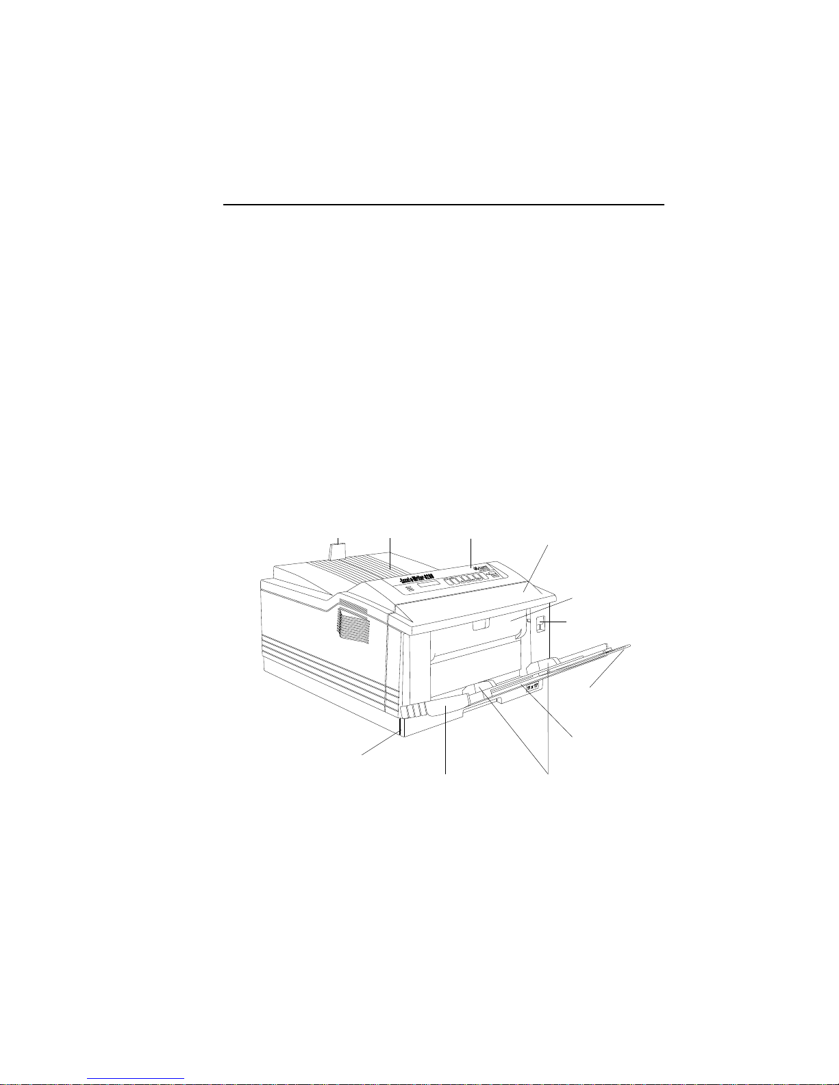
Before you begin this setup, take a few minutes to look over figures
2.1 and 2.2 to familiarize yourself with the printer.
Paper
Stop
Output
Tray
Paper Cassette Slot
Fig. 2.1 Front View of the Printer
Front
Panel
ENTER
TEST
RESET
®
FORM
FEED
ON LINE
MANUAL
READY
Fold Down Tray
Front Cover
TRAY
MENU
SELECT
Fuser
Cover
Release
Latch
Ledger
Extender
Tray
Extender
Paper Guides
__________________________________________ Installation 2-5
Page 6
Output Tray Interface Ports
Power
Switch
Feeder Tray
Connector Cover
Power
Receptacle
Cassette Cover
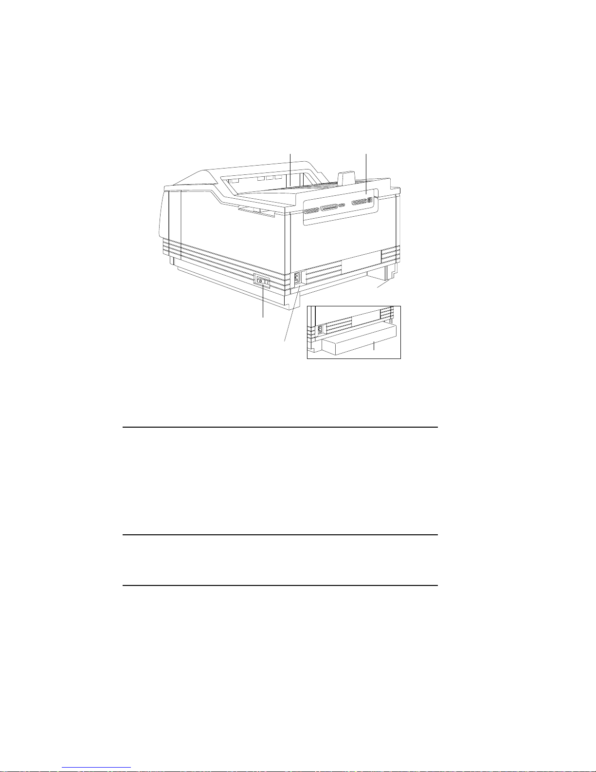
Fig. 2.2 Rear View of the Printer
Unpacking the Printer
Various packing materials protect your printer during shipping. These
materials include plastic, tape, polystyrene, cardboard, and shipping
spacers—all of which must be removed. You may want to save these
materials in case you ever have to move or ship the printer.
1. Remove everything except the printer in its protective bag
from the shipping box.
Warning! The printer weighs approximately 51 lbs (23 kg)
without the toner, cassettes, and media installed. Have
someone help you lift it.
2. Lift the printer out of the box.
3. Remove the plastic wrap from around the printer.
2-6 Installationbb_________________________________________
Page 7
4. Remove the three pieces of tape securing the fold down tray.
The tape is located at the top and on each side of the tray.
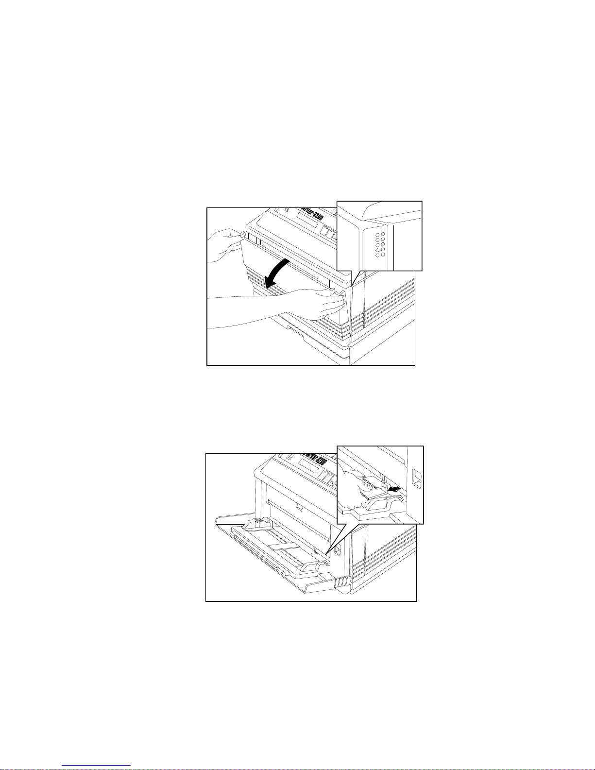
5. Open the fold down tray by grasping the top corners and
pulling out and down (fig. 2.3).
ACTIVE
MANUAL
READY
READY/IDLE
ON LINE
FORM
FEED
RE
Fig. 2.3 Open the Fold Down Tray
6. Locate the shipping cardboard in the lower right corner of the
front cover. Then, pull it straight out to remove it (fig. 2.4).
ACTIVE
MANUAL
READY
®
READY/IDLE
ON LINE
FORM
FEED
RESET
TEST
ENTER
Innovations In Output
MENU
TRAY
SELECT
Fig. 2.4 Remove the Shipping Cardboard
__________________________________________ Installation 2-7
Page 8
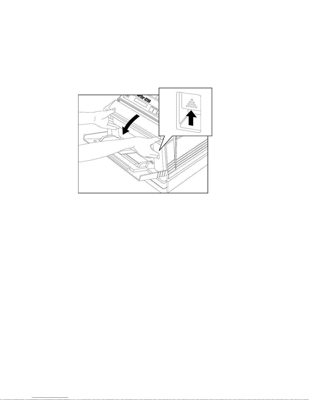
7. Open the front cover by lifting the release latch and tilting the
cover towards you (fig. 2.5).
ACTIVE
MANUAL
READY
PRINTER OPEN
ON LINE
FORM
FEED
RE
Fig. 2.5 Open the Front Cover
2-8 Installationbb_________________________________________
Page 9
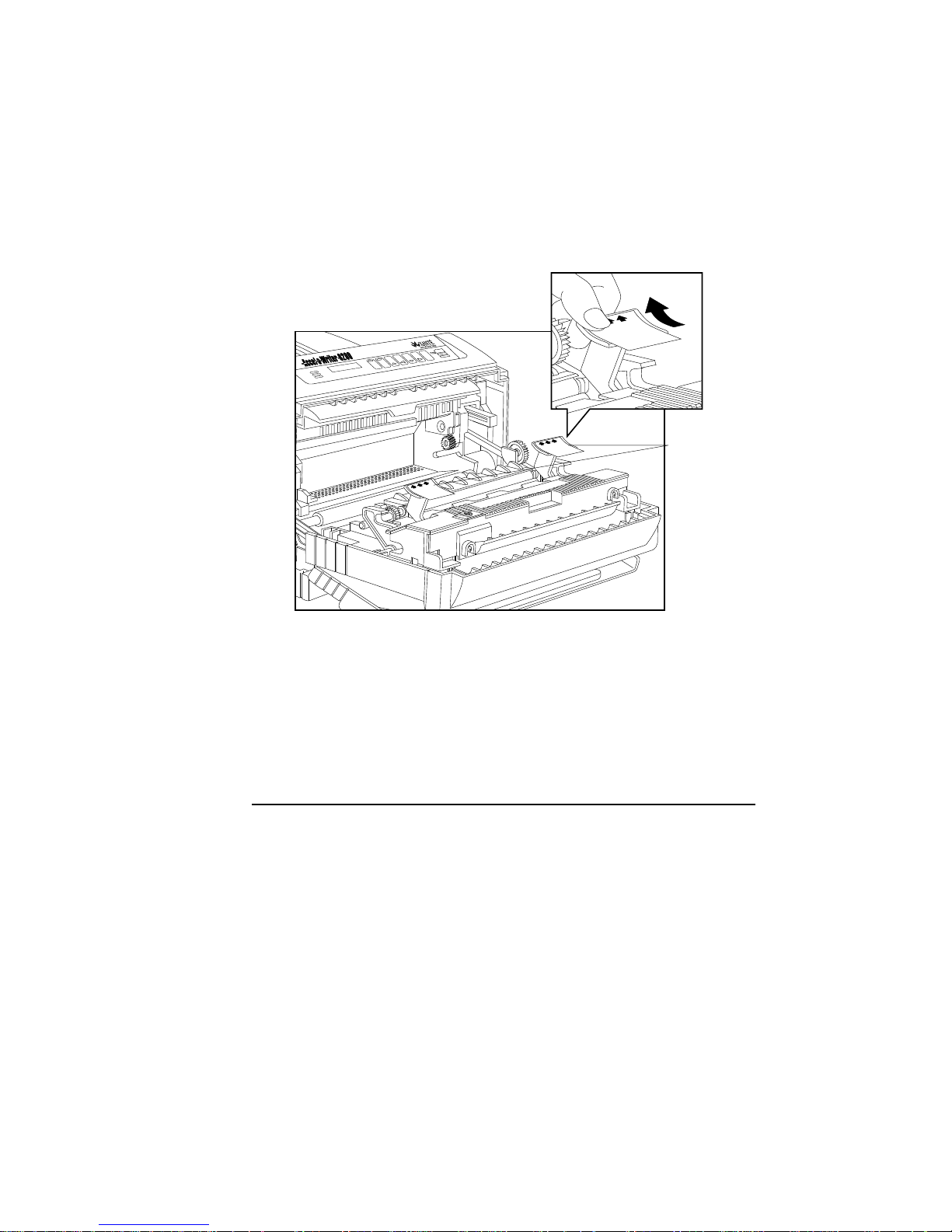
8. Remove the two orange shipping spacers by pulling them up
and back in the direction of the arrows (fig. 2.6).
Remove
•
this spacer
Enlever
•
TRAY
MENU
SELECT
ENTER
TEST
®
MANUAL
READY
RESET
FORM
FEED
ON LINE
cette cale.
Shipping
Spacers
Remove
•
this spacer
Enlever
•
cette cale.
Remove
•
this spacer
Enlever
•
cette cale.
Fig. 2.6 Remove the Two Shipping Spacers
If you did not purchase the optional paper feeder or the 500 sheet
letter/A4 paper cassette with the cassette supporter, skip to
“Installing the Toner Cartridge.”
Installing Options
If you have an optional paper feeder or the 500 sheet letter/A4 paper
cassette with the cassette supporter, unpack the option(s) now.
Follow the installation instructions included with the option(s). See
“Tray Chaining” in chapter 6 for details on using optional trays.
__________________________________________ Installation 2-9
Page 10
Installing the Toner Cartridge
Caution: The toner cartridge is sensitive to bright lights and direct
sunlight. Leave it in its protective bag until you are ready to
load it into the printer. The cartridge contains a magnet, so
keep it away from your hard disk(s) and monitor to prevent
possible data loss or equipment damage.
The standard Accel-a-Writer 8200 ships with an EP-BII toner
cartridge. If you purchased the extra wide print option with your
printer, it ships with the EP-BIIX extra wide cartridge. Both
cartridges load in the same manner.
Use the following procedure to install the toner cartridge.
1. If the fold down tray is closed, open it by grasping the top
corners and pulling out and down (fig. 2.3).
2. If the front cover is closed, open it by lifting the release latch
and tilting the cover towards you (fig. 2.5).
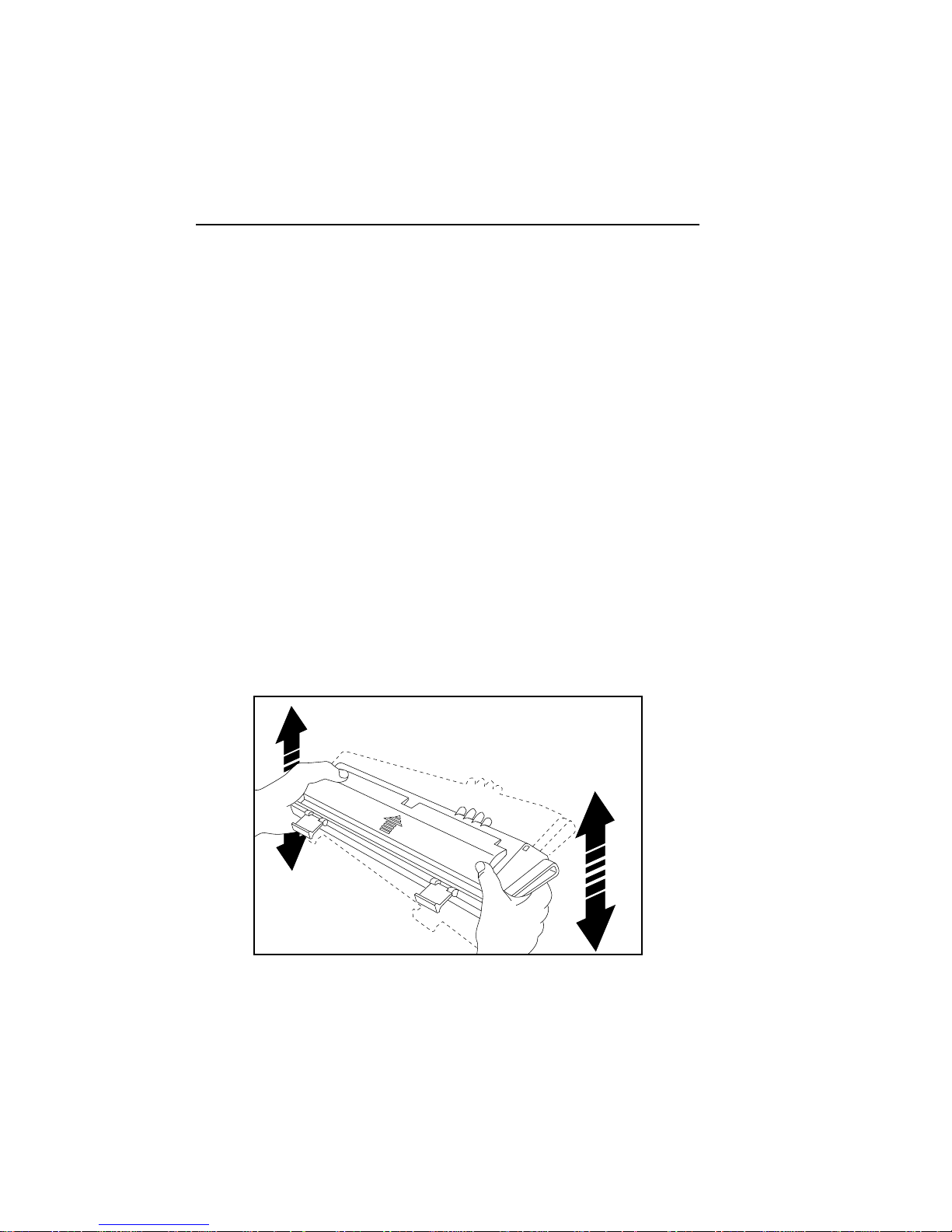
3. Remove the toner cartridge from its package and gently rock it
back and forth to distribute the toner evenly throughout the
cartridge (fig. 2.7).
2-10 Installationbb_________________________________________
Fig. 2.7 Distribute the Toner
Page 11
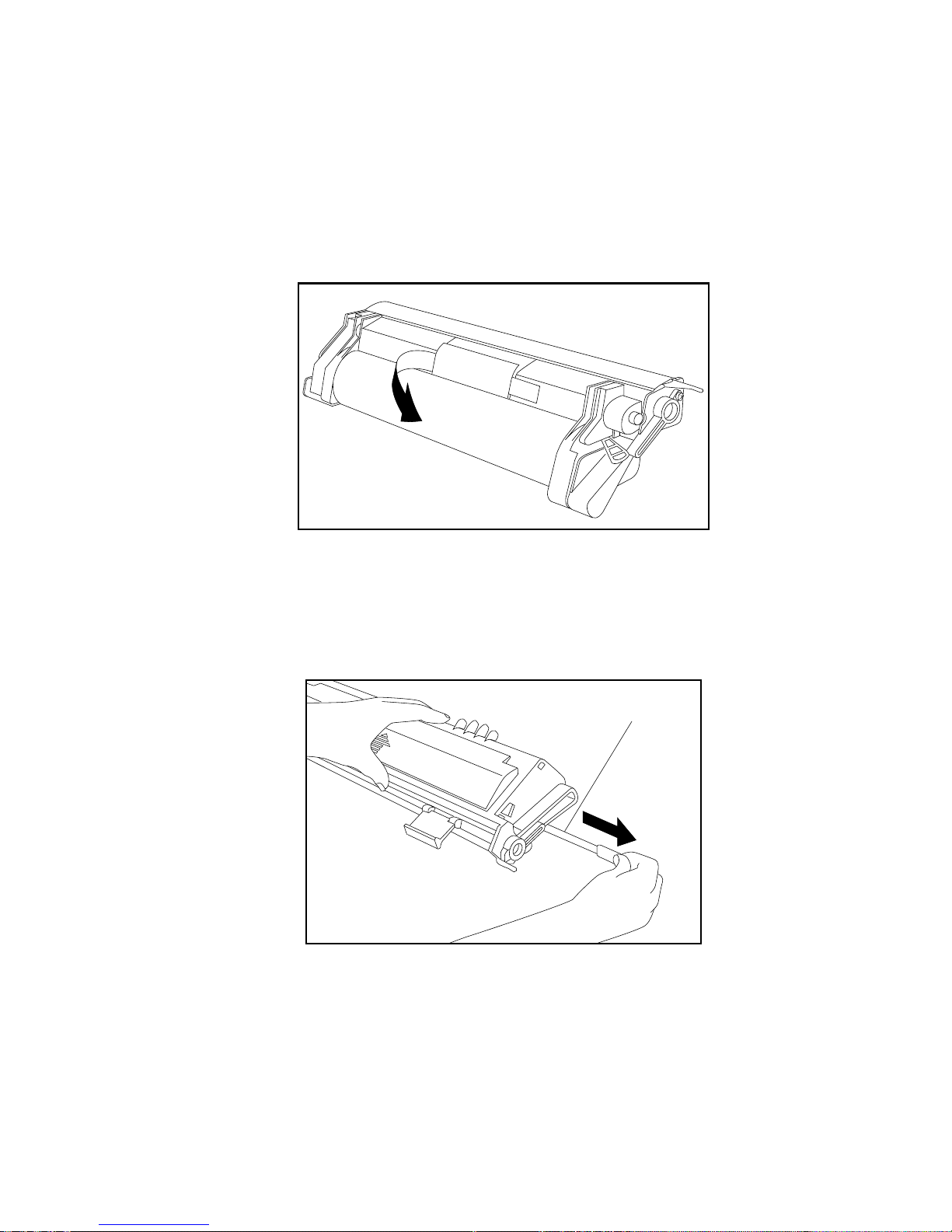
4. Grasp the center tab labeled “Remove the black sheet slowly”
and gently pull out and discard the protective black plastic
sheet from the toner cartridge (fig. 2.8).
Fig. 2.8 Remove the Plastic Protective Sheet and Tape
5. Gently flex the orange tab on the end of the sealing tape back
and forth until it becomes loose. Then, pull the tab and tape
from the toner cartridge and discard it (fig. 2.9).
Tape Seal
Fig. 2.9 Remove the Toner Sealing Tape
__________________________________________ Installation 2-11
Page 12
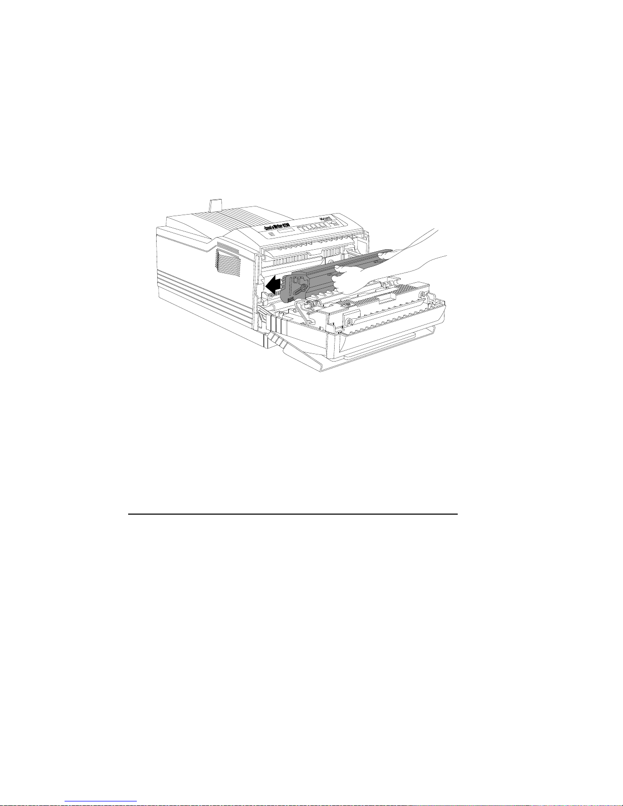
6. Holding the toner cartridge by the two green tabs (fig. 2.10),
align it on the runners inside the printer, and slide the cartridge
into the printer until it rests securely in place.
TRAY
MENU
SELECT
ENTER
TEST
RESET
®
FORM
FEED
ON LINE
MANUAL
READY
Fig. 2.10 Load the Toner Cartridge
7. Close the printer’s front cover until it clicks in place.
8. Close the fold down tray.
Note: Never move or ship the printer with a toner cartridge installed.
Loading the Paper Cassette
Two 250 sheet paper cassettes (one letter/A4 and one ledger (11" x
17")/A3) ship with your Accel-a-Writer 8200. This section includes
instructions for loading the letter/A4 size cassette with laser quality
or 20 lb photocopier paper.
Refilling a cassette, printing on other types of media (transparencies,
labels, and envelopes), and printing on other sizes are covered in
chapter 6, “Routine Operations.” That chapter also covers selecting
and storing media.
2-12 Installationbb_________________________________________
Page 13
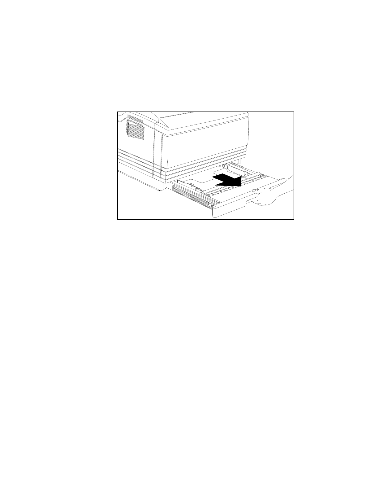
Use the following procedure to load the letter/A4 cassette.
1. Pull the paper cassette straight out from the printer (fig. 2.11).
Fig. 2.11 Remove the Paper Cassette
2. Prepare up to 250 sheets (approximately 1" [25 mm] thick or
less) of laser quality or 20 lb photocopier paper. To do this:
a. Make sure the paper meets all the requirements in
“Selecting Media” in chapter 6.
b. Determine the printing side of the paper. The wrapper on
most paper packages has an arrow pointing in the
direction of the printing side.
c. Fan the paper to prevent it from sticking together, and
then align the edges to form a smooth stack.
__________________________________________ Installation 2-13
Page 14
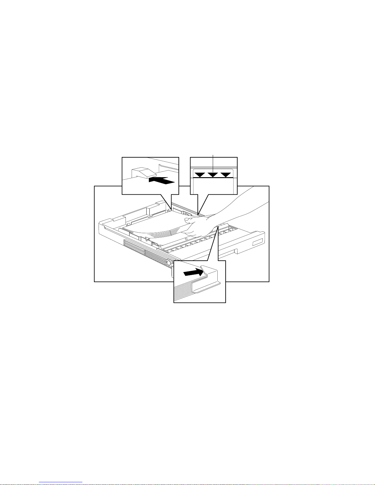
3. Slide the paper printing ‹de up, long edge first under the two
plastic clips at the rear of the cassette and the two metal clips
at the front corners of the cassette.
Caution: Make sure the paper stack does not exceed the
upper paper limit marked on the cassette (fig. 2.12).
Overloading a cassette will cause paper to jam.
Paper Limit Mark
LETTER
2-14 Installationbb_________________________________________
Fig. 2.12 Load the Paper Cassette
Page 15
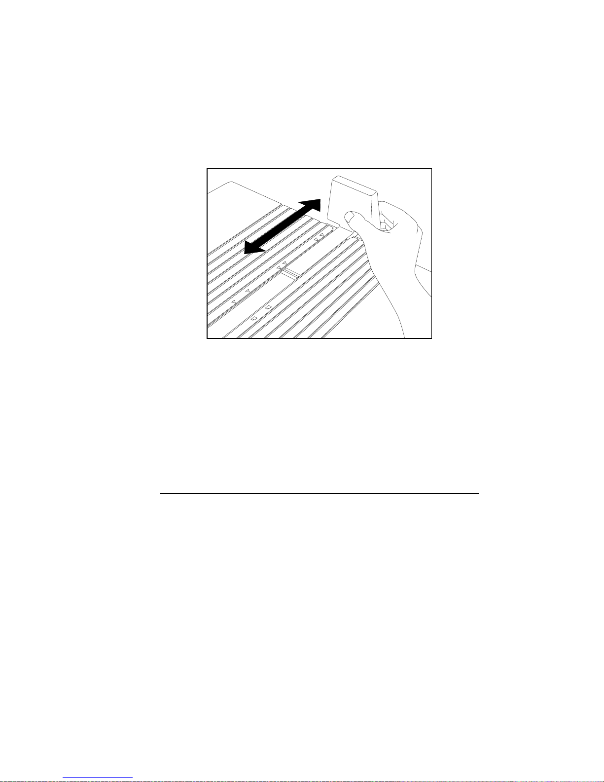
4. Adjust the paper stop on the output tray for the size media you
are using (fig. 2.13).
11x17
A3
B4
LGL
A4
LTR
Fig. 2.13 Adjust the Paper Stop
5. Slide the cassette into the printer until it snaps into place.
Note: If you install the ledger (11" x 17")/A3 paper cassette,
you should install the rear cassette cover. For cover
installation details, see “Feeding Media to the Printer”
in chapter 6.
Loading the Fold Down Tray
Your Accel-a-Writer 8200 has a built-in fold down tray on the front.
You can use the tray to feed up to 100 sheets of standard letter/A4,
legal/special A4, or ledger (11" x 17")/A3 sized media. You also can
use the tray to feed envelopes and variable custom sized media
measuring between 3.90" to 5.80" (99 mm x 147 mm) and 11.81" to
25.00" (300 mm x 635 mm).
Note: With the extra wide print option, you can print 12.00" x
19.00" and 12.00" x 25.00" paper with respective print
regions of 11.97" x 18.93" and 11.97" x 24.93" using the
fold down tray.
__________________________________________ Installation 2-15
Page 16
This section includes instructions for loading letter/A4 size laser
quality or 20 lb photocopier paper. Refilling the tray, printing on
other types of media (transparencies, labels, and envelopes), and
printing on other sizes are covered in chapter 6.
Use the following procedure to load the fold down tray.
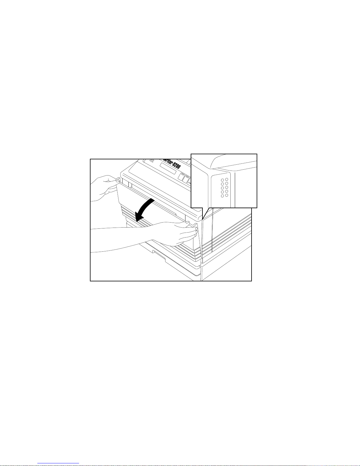
1. Open the fold down tray by grasping the top corners and
pulling out and down (fig. 2.14).
ACTIVE
MANUAL
READY
READY/IDLE
ON LINE
FORM
FEED
RE
2-16 Installationbb_________________________________________
Fig. 2.14 Open the Fold Down Tray
Page 17
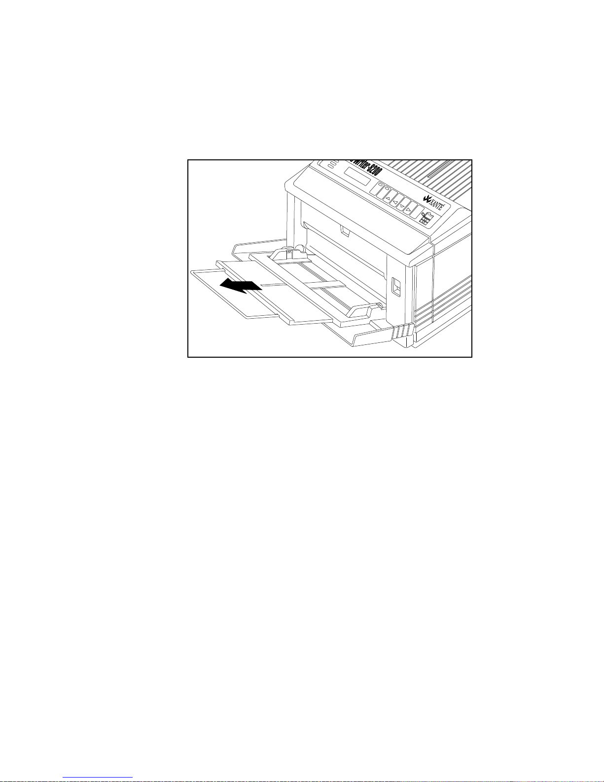
2. Pull out the tray extender (fig. 2.15).
ACTIVE
MANUAL
READY
READY/IDLE
®
ON LINE
FORM
FEED
RESET
TEST
ENTER
Innovations In Output
MENU
TRAY
SELECT
Fig. 2.15 Pull Out the Tray Extender
3. Prepare up to 100 sheets (approximately 3/8" [10 mm] or less)
of laser quality or 20 lb photocopier paper. To do this:
a. Make sure the paper meets all the requirements listed in
“Media Handling” in chapter 6.
b. Determine the printing side of the paper. Most packages
of paper have an arrow pointing in the direction of the
printing side on the wrapper.
c. Fan the paper to prevent it from sticking together, and
then align the edges to form a smooth stack.
__________________________________________ Installation 2-17
Page 18
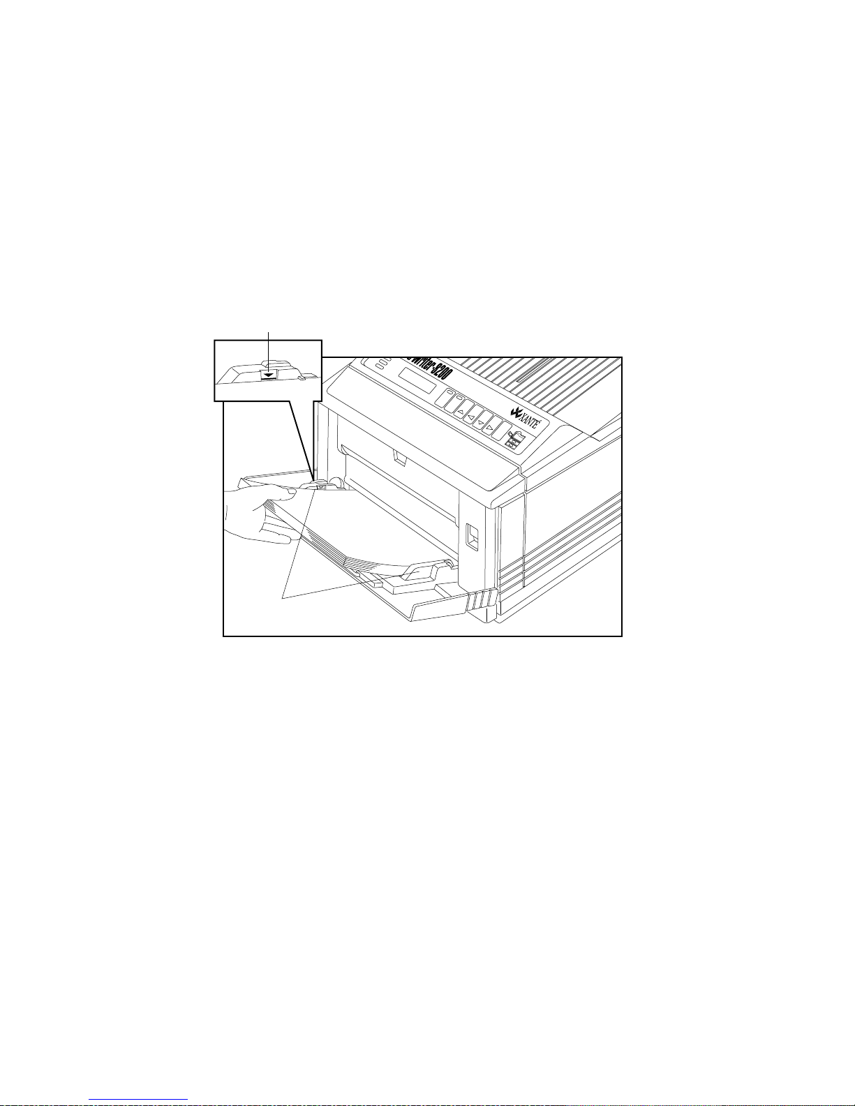
4. Slide the paper printing side down into the fold down tray (fig.
2.16).
Caution: Make sure the paper stack does not exceed the
upper paper limit marked on the tray (fig. 2.16).
Overloading the tray will cause paper to jam.
Paper Limit Mark
ACTIVE
MANUAL
READY
READY/IDLE
®
ON LINE
FORM
FEED
RESET
TEST
ENTER
Innovations In Output
MENU
TRAY
SELECT
Paper
Guides
Fig. 2.16 Load the Fold Down Tray
5. Adjust the paper guides on each side so they rest lightly
against the paper without causing it to buckle (fig. 2.16).
6. Adjust the output tray’s paper stop for the size media you are
using (fig. 2.13).
2-18 Installationbb_________________________________________
Page 19

Connecting the Power Cord
The power connector is on the back of the printer at the lower left.
1. Make sure the printer’s power switch is off (the O is pressed in).
2. Connect one end of the power cord to the printer.
3. Connect the other end of the power cord to a standard
electrical outlet (grounded AC outlet).
Note: You may want to use a surge protected outlet to help prevent
power source fluctuations from damaging your printer.
Surge protectors are available through most office supply
and computer stores.
Starting the Printer
The power switch is on the lower left side of the printer.
1. Locate the power switch.
2. Press the | on the power switch to turn on the printer. The
green Ready light will begin flashing and Accel-a-Writer
appears in the display window.
After the printer is powered on, it goes through a warm-up period of
approximately 90 seconds. During this time the printer runs
initializing programs and self-tests. After the warm-up period, the
Ready light stops flashing and remains on. The start-up page
automatically prints. See the next section, “Printing the Start-up
Page,” for details on this page.
If your printer does not power on when you turn the switch on, check
the following:
• Is the AC power cord attached properly?
• Is the power switch in the ON position?
__________________________________________ Installation 2-19
Page 20
Printing the Start-up Page
When you turn the printer on for the first time, it prints a start-up
page in approximately 90 seconds. The printer does not have to be
attached to a host to print this page.
Note: Printing time for the start-up page varies depending on the
selected printing resolution. The lower the resolution, the
faster the start-up page prints.
The start-up page contains configuration information concerning
your printer. This information includes the printer name, RAM size,
page count, resolution, hard disk information, and the current
firmware version.
This page prints each time you start the printer unless you disable it. Use
the front panel or XANTÉ Command Center to disable this feature.
If you decide to disable this page, make sure to keep a copy for
reference in case you want to check your printer setup. To disable
this feature, see “Turning the Start-up Page Off or On” either in
chapter 3 for a Macintosh environment or chapter 4 for a PC
environment.
Selecting an Interface
Once the printer is set up, you need to select an interface to connect
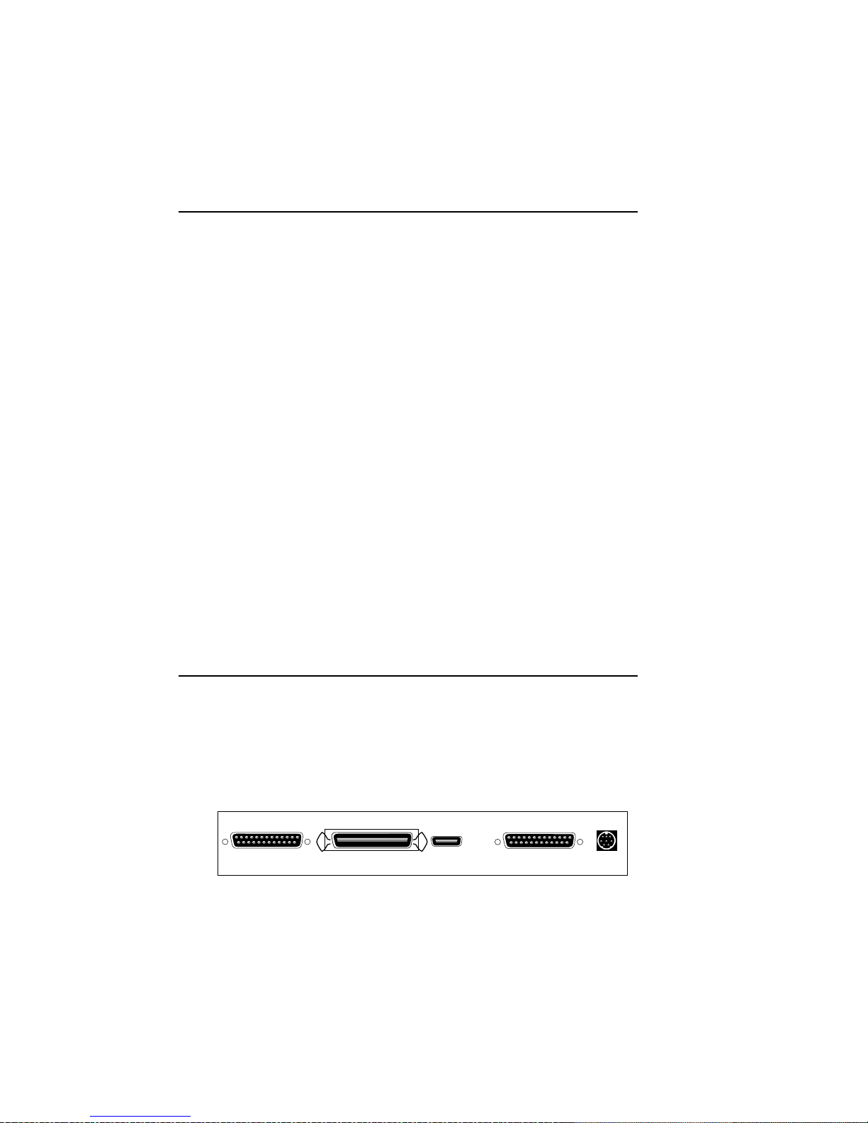
the printer to the host. Your Accel-a-Writer 8200 has three standard
interface ports on the back—LocalTalk, serial, and parallel. There is
a SCSI port where you can attach multiple external hard disks, and
an optional Ethernet port.
SCSI
Fig. 2.17 Accel-a-Writer 8200 Ports
2-20 Installationbb_________________________________________
Serial LocalTalkParallel Ethernet
Page 21
The serial, parallel, LocalTalk, and (optional) EtherTalk ports are
simultaneously active, which allows you to access the printer
through multiple ports at the same time. The printer prints the first
incoming job. When the first job finishes, the next job (in the order
received) prints, and so forth until all jobs print.
The port you should select depends on many variables, such as your
type of host, the available host ports, your software application,
printer drivers, and emulations.
Caution: DO NOT confuse the serial and SCSI interface ports
when connecting cables. This will cause permanent
printer damage which is not covered under the warranty.
The printer ports are labeled clearly.
If you have an Ethernet setup, skip to “Connecting to the Ethernet
Port” later in this chapter. If you have a PC setup, skip to
“Connecting in a PC Environment” later in this chapter. If you have
a Macintosh setup without Ethernet, go to the next section,
“Connecting in a Macintosh Environment.”
Connecting in a Macintosh Environment
In the Macintosh environment without Ethernet, your host system
communicates with the printer via the LocalTalk port.
Connecting to the LocalTalk Port
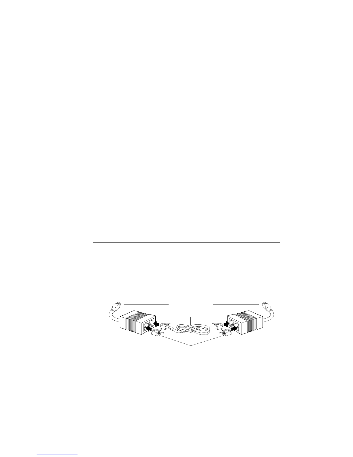
You will need two LocalTalk connector boxes with DIN-8
connectors, a standard phone cable (RJ-11), and two terminators.
DIN-8 Connector
RJ-11 Cable
Connector
Box
Fig. 2.18 Connecting to the LocalTalk port
Terminating
Resistor
__________________________________________ Installation 2-21
Connector
Box
Page 22
To connect your printer via the LocalTalk port, use the following
procedure.
1. Turn off your printer and your host computer.
2. Plug the DIN-8 connector on one LocalTalk connector box
into the 8-pin LocalTalk port on the back of the printer.
3. Plug the DIN-8 connector on the second LocalTalk connector
box into the printer port on your Macintosh (refer to your
Apple Macintosh manual).
4. Connect the two LocalTalk connector boxes with the RJ-11
phone cable.
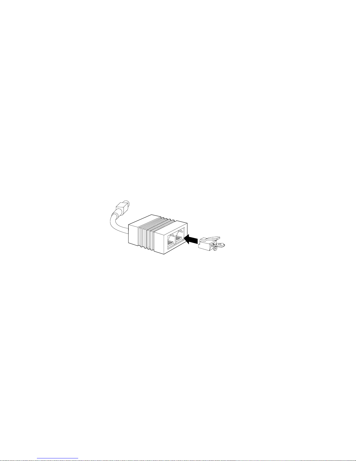
5. Plug the terminating resistor(s) into the open socket(s) in the
connector box(es).
Fig. 2.19 Place a Terminating Resistor in the Open Socket
Note: Be sure to terminate the open sockets on the ends of your
LocalTalk network with the terminators supplied with
your LocalTalk connectors (fig. 2.19). (There should
only be two open sockets on the network, one at each
end.) Closing open sockets helps speed data transmission
and helps ensure the printer is available in the Chooser.
6. Turn on the printer and host computer.
7. Select the Chooser from the Apple menu on your Macintosh
computer. The Chooser window opens.
8. Click the appropriate LaserWriter icon in the left side of the
window.
2-22 Installationbb_________________________________________
Page 23

9. Select the Accel-a-Writer 8200 in the right side of the Chooser
window.
If you work on a network and need to connect a second host to
another printer port, skip to the section on connecting to the desired
port later in this chapter. If not and you are connecting an optional
hard disk, skip to “Connecting a Hard Disk” later in this chapter.
Otherwise, skip to the next chapter, “Macintosh Setup.”
Connecting in a PC Environment
In a PC environment, your host system should communicate with the
printer via the parallel port or serial port.
Parallel communication is faster than serial communication, but it is
restricted to one-way communication from the host to the printer.
Serial communication allows two-way communication between the
host and printer.
Use the parallel port if your host has a Centronics parallel port
available and it is within 10 ft. (3 m) of the printer. Use serial
communication when a parallel port is not available on the host, if
the host is between 10 ft. (3 m) and 25 ft. (7.6 m) from the printer, or
if your host requires two-way communication with the printer.
If you are connecting via the serial port, skip to “Connecting to the
Serial Port” later in this chapter.
Connecting to the Parallel Port
You need a standard Centronics parallel cable to connect your host
and printer (fig. 2.20). The parallel port on the rear of the printer uses
a 36-pin connector. The parallel port on your host computer uses a
25-pin connector.
__________________________________________ Installation 2-23
Page 24
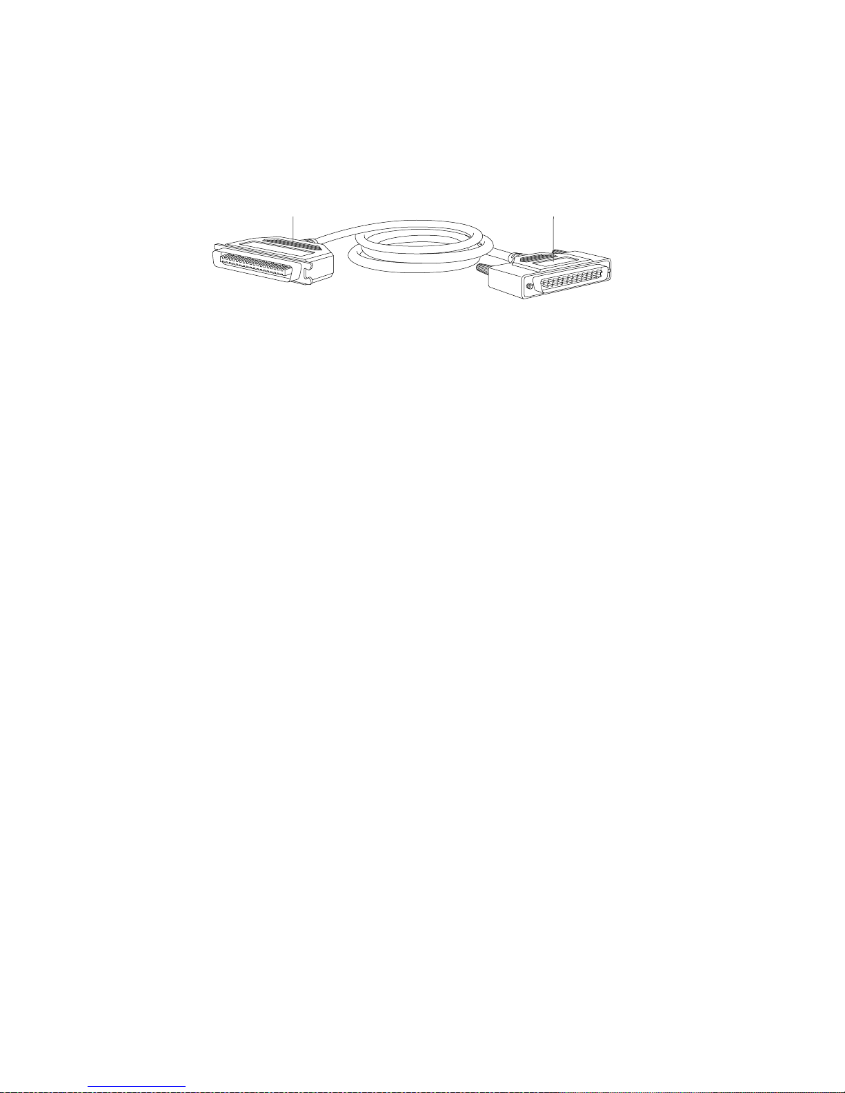
36-pin Connector
To Printer
Fig. 2.20 The Parallel Cable
25-pin Connector
To Host Computer
Use the following procedure to connect your printer and host using
the parallel port.
1. Turn off your printer and host computer.
2. Plug the 36-pin connector end of the parallel cable into the
parallel port on the back of the printer (fig. 2.20).
3. Plug the cable’s 25-pin end into the parallel port on your host.
4. Turn on your host and then the printer.
If you work on a network and need to connect a second host to
another printer port, skip to the section on connecting to the desired
port later in this chapter. If not and you are connecting an optional
hard disk, skip to “Connecting a Hard Disk” later in this chapter.
Otherwise, skip to chapter 4, “PC Setup.”
Connecting to the Serial Port
Connecting to the serial port involves two areas:
• Connecting the printer and host
• Making sure printer, host, and application settings match
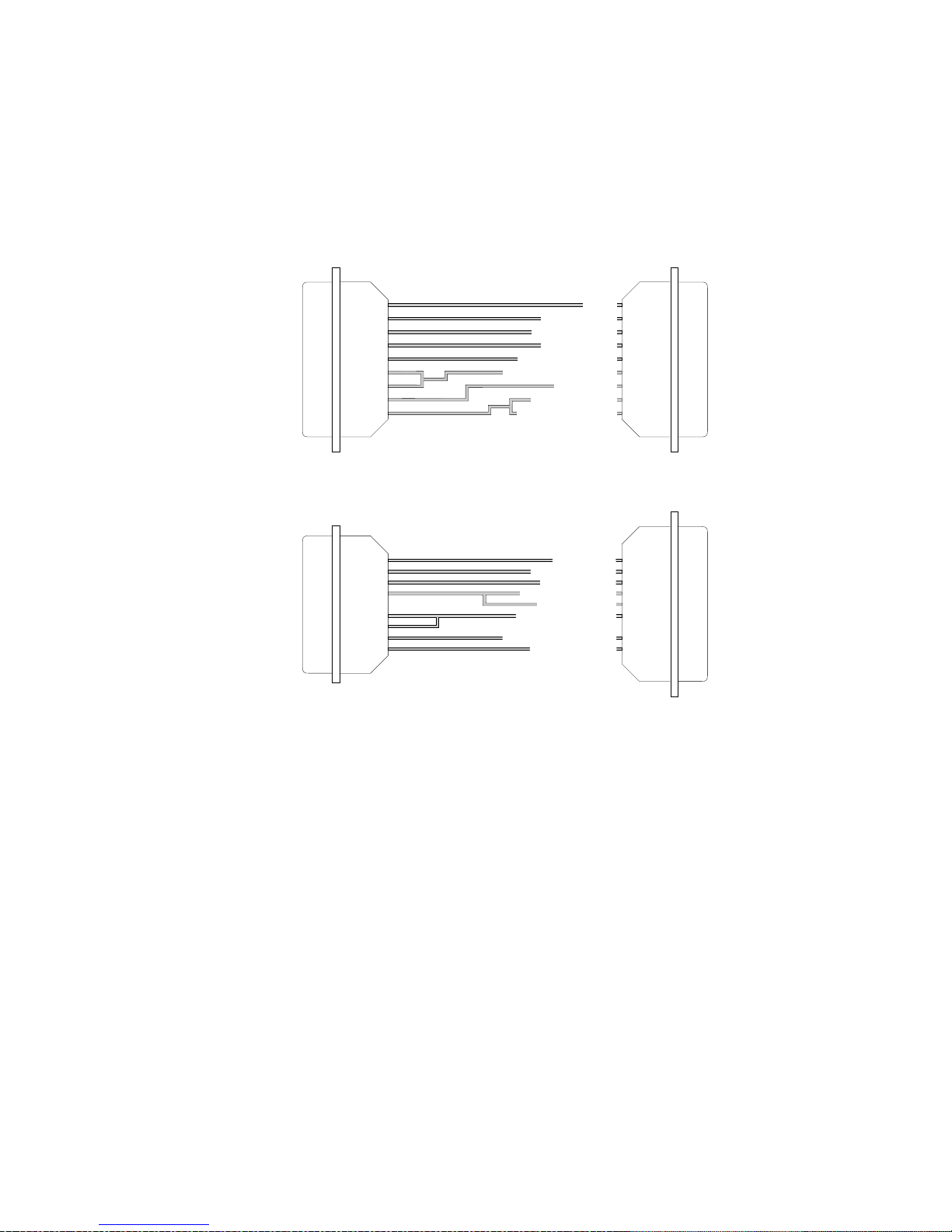
You need a standard null-modem serial cable to connect your host
and printer (fig. 2.21). The serial port on the rear of the printer uses a
25-pin (DB-25) connector. The serial port on your host uses either a
25-pin connector or a 9-pin connector.
2-24 Installationbb_________________________________________
Page 25
PC
Printer
DB-25
(Female)
PC
DB-9
(Female)
20
1
2
3
4
5
6
8
7
Transmit Data (Out)
Request for Send (Out)
Data Terminal Ready (Out)
Data Set Ready (In)
Data Carrier Detect (In)
Ground
Receive Data (In)
Clear to Send (In)
Signal Ground
1
3
2
5
4
20
7
6
8
DB-25
(Male)
Printer
5
2
3
1
7
8
6
4
Data Terminal Ready (Out)
Signal Ground
Transmit Data (Out)
Receive Data (In)
Request to Send (Out)
Clear to Send (In)
Data Carrier Detect (In)
Data Set Ready (In)
20
7
2
3
4
5
8
6
DB-25
DB-25
(Male)
Use the following procedure to connect your printer and host using
the serial port.
Caution: DO NOT confuse the serial and SCSI interface ports
1. Turn the power off to your printer and host.
__________________________________________ Installation 2-25
Figure 2.21 Serial Cable Pin-outs
when connecting the cables. This will cause permanent
printer damage which is not covered under the warranty.
The printer ports are labeled clearly.
Page 26

2. Plug the 25-pin (DB-25) male connector end of the serial cable
into the serial port on the back of your printer (fig. 2.21).
3. Plug the other end of the serial cable (with either a 25-pin or
9-pin connector) into the serial port on your host.
Now, your printer and host are connected. However, before you
print, make sure your host, printer, and application are using the
same communication settings. The three settings which must match are
• Baud Rate
• Flow Control
• Parity
The factory default printer settings are 9600 baud, XON/XOFF flow
control, and No Parity (None). These settings are used in most serial
printing environments.
Note: Your Accel-a-Writer 8200 always uses 8 data bits.
Baud Rate
The baud rate is the rate at which serial data is sent between the host
and the printer. Your Accel-a-Writer 8200 supports 1200, 9600, and
19200 baud rates. The printer’s factory default is 9600.
See your host manual for details on checking and setting up the host
serial interface. You can check and set the baud rate for your
Accel-a-Writer 8200 through the printer’s front panel or use the
procedure in “Changing Serial Communication Settings” later in this
chapter. See chapter 5, “Configuration,” for front panel setup
information.
Flow Control
Flow control is how the printer signals the host that the printer is
ready to accept data. The Accel-a-Writer 8200 supports both
XON/XOFF (software) and DTR/DSR (hardware) flow control. The
printer’s factory default is XON/XOFF.
It is very important for both the host computer and printer to agree
on flow control. Incorrect flow control causes erratic serial printing.
2-26 Installationbb_________________________________________
Page 27

You can check and set the flow control through the printer’s front
panel or use the procedure in “Changing Serial Communication
Settings” later in this chapter. See chapter 5, “Configuration,” for
front panel setup information.
Parity
Parity is the grouping of data bits into a uniform size. If some data is
lost or damaged in transmission, chances are high that it will affect
the size of a group, providing a warning of transmission errors. Your
Accel-a-Writer 8200 supports five parity settings, None, Even, Odd,
Mark, and Space. The printer’s factory default is None. The
PostScript command “setdevparams” defines the parity of the serial
channel for PostScript Level 2.
Changing Serial Communication Settings
The easiest way to change serial communications is to use the printer
front panel. See “Selecting Menu Options” in chapter 5 for details.
You can also change settings by creating a PostScript file and
sending it to the printer. This is handy if you are networked to a
printer away from your host. The following “text only” sample file
changes the serial channel to 9600 baud, XON/XOFF, and None
parity.
true 0 startjob pop
(%Serial%) <</Baud 9600 /Parity /None
/FlowControl /XonXoff>>
setdevparams
Now your printer and host are connected. If you are not connecting
an optional hard disk, go to chapter 4, “PC Setup.”
Connecting to the Ethernet Port
Two methods can be used to connect to your printer’s Ethernet port.
One method uses an Unshielded Twisted Pair (UTP) or 10BaseT
connection, and the other uses thin coaxial cable (10Base2)
connection.
__________________________________________ Installation 2-27
Page 28
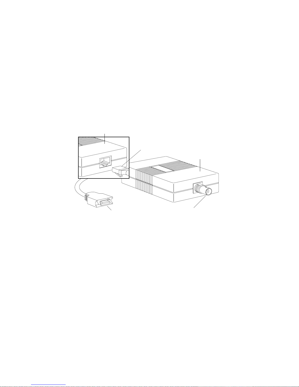
Both methods require an external transceiver which is available from
most computer stores or mail-order warehouses. The transceiver
should have an Apple AUI (Attachment Unit Interface) connector on
one end and either an Unshielded Twisted Pair (UTP or 10BaseT)
cable or a thin coaxial connection (ThinNet, CheaperNet, or
10Base2) on the other end. Figure 2.22 illustrates an example of both
a 10Base2 and a 10BaseT transceiver; however, designs vary slightly
among transceiver brands.
10BaseT
Transceiver
Unshielded
Twisted Pair
RJ-45
10Base2
Transceiver
Apple AUI Connector
(To Printer)
Fig. 2.22 Ethernet Transceivers and Cables
Thin Coaxial
Cable Connection
Note: When you connect to an EtherTalk network, you must select
EtherTalk Phase 2. Select the phase on your Macintosh
through the Network CDEV (Control panel DEVice) under
the Control Panel. The Phase 2 icon usually has two double
arrows.
Unshielded Twisted Pair (10BaseT) Connection
This configuration uses ordinary wiring for data transmission. UTP
requires a hub to which each device (for example the host computer
or the printer) is connected. Hubs can be linked together to form a
larger network.
2-28 Installationbb_________________________________________
Page 29

A UTP cable looks like ordinary telephone wire. Each end has an
RJ-45 plug which looks like a slightly-larger version of the standard
telephone plug (fig. 2.22). The UTP cable should be a maximum of
328 ft. (100 m) in length. No cable terminators are necessary.
To connect your printer via the Ethernet port using the UTP method,
use the following procedure.
1. Turn off the printer.
2. Plug the transceiver’s Apple AUI connector (fig. 2.22) into the
Ethernet port on the printer.
3. Plug one end of the UTP cable into the RJ-45 socket on the
transceiver, and plug the other end into an RJ-45 socket on the
network’s hub.
4. Turn on the printer.
Now that your Macintosh and printer are connected, you may need to
set the zone name. For details, skip to “Setting the EtherTalk Zone
Name” later in this chapter.
Thin Coaxial Cable (10Base2) Connection
This configuration uses coaxial cable. Thinnet networks connect in a
daisy-chain configuration with each of the two ends terminated with
either a 50-Ohm terminating resistor or a self-terminating transceiver
box. The maximum cable length for a network segment is 607 ft.
(185 m). However, devices such as repeaters, routers, and gateways
may be inserted to increase the overall length of the network or to
connect to other networks.
__________________________________________ Installation 2-29
Page 30
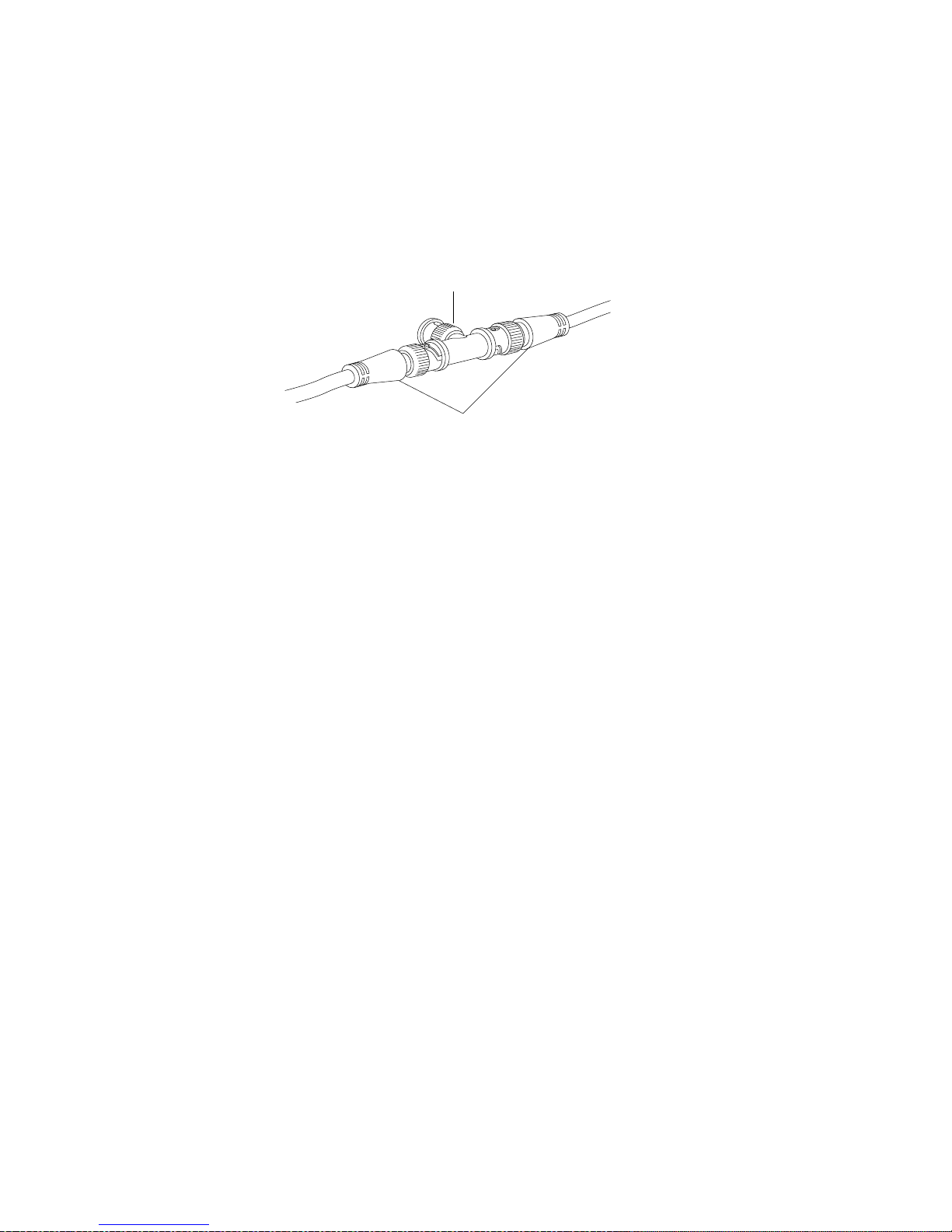
Thinnet cables usually have a female twist-on BNC connector on
each end. A “T” connector is used to tie the external transceiver into
the network (fig. 2.23).
T Connection
Coaxial Cable
Fig. 2.23 A “T” Connector
Some external transceiver boxes are self-terminating. This means
that they do not require a termination resistor if they are the last box
on a network. If the box is at one end of a network and not selfterminating, you must place a terminating resistor in the open socket.
To connect your printer via the Ethernet port using the thin coaxial
cable method, use the following procedure.
1. Turn off the printer.
2. Plug the transceiver’s Apple AUI connector (fig. 2.22) into the
Ethernet port on the printer.
3. Connect the transceiver to one end of the coaxial cable. To do
this use one of the following procedures:
a. If the transceiver box has a single male BNC connector,
either plug it into an existing Ethernet drop or use a “T”
connector (fig. 2.24). Follow the directions included
with the transceiver.
Note: Make sure to place a terminator in the open
connector if this is an end node on the network
(fig. 2.24).
2-30 Installationbb_________________________________________
Page 31
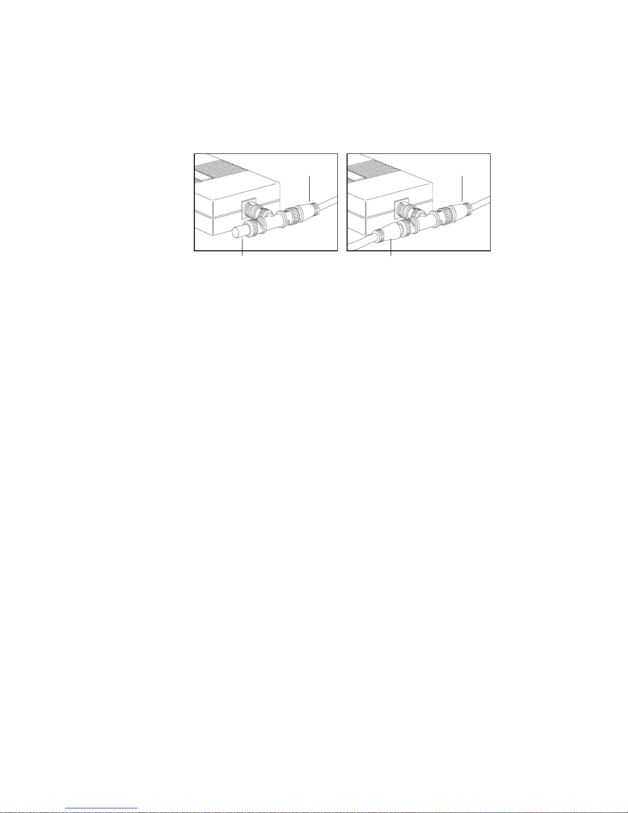
10Base2 T erminated T Connection
10Base2 Inline T Connection
Coaxial Cable
Termination Resistor
Fig. 2.24 Connecting to a single BNC Connector
Coaxial Cable
Coaxial Cable
b. If the transceiver box has dual male BNC connectors,
first check the documentation to see if the unit is
self-terminating. Then, follow the instructions included
with the transceiver to attach one end of the coaxial
cable to the box.
Note: You can plug the coaxial cable into either one of
the male connectors; however, make sure that if
this is an end-node on the network and the unit
is not self-terminating, that you place a
terminator in the open socket on the box.
4. Plug the free end of the coaxial cable into the network.
5. Turn on the printer.
Now that your Macintosh and printer are connected, you may need to
set the zone name. For details, see the next section.
Setting the EtherTalk Zone Name
If you need to set the EtherTalk zone name to a name other than the
default name supplied by your router, you can do this by creating and
downloading a PostScript file to the printer. You can use the Adobe
Font Downloader in the XANTÉ Utilities to send this file to the
printer.
__________________________________________ Installation 2-31
Page 32

When you create the file, zone names are limited to 32 characters
and should not contain the equal sign (=), the approximately equal
sign (≈), and the asterisk (*). For example, to name your zone
“Marketing - First Floor” using the procedure later in this section,
you would type the following in step 3.
(%EtherTalk_NV%) << /EtherTalkZone (Marketing-First
Floor) >>setdevparams
Note: Check with the system administrator to find out what zone
name to use.
To set the EtherTalk zone name, use the following procedure.
1. Open the TeachText program which came with your
Macintosh.
2. Select New from the File menu.
3. Type the following file substituting the name for the zone used
on your network for nameofzone.
(%EtherTalk_NV%)<</EtherTalkZone(nameofzone)
>>setdevparams
4. Select Save from the File menu, and save the file as Set
Zone.ps on your host system.
5. Select Quit from the File menu to exit TeachText.
6. Insert the Macintosh XANTÉ Utilities disk included with your
printer.
7. Open the Utilities folder.
8. Double-click the Downloader icon to open that utility.
9. Choose Download PostScript File from the File menu.
10. Locate the Set Zone.ps file which you created in step 3.
2-32 Installationbb_________________________________________
Page 33

11. Select the Set Zone.ps file and click Download. The following
status message appears when the downloading is complete.
The download was successful.
12. Click OK.
13. Select Quit from the File menu.
14. Turn the power to the printer off and on again.
If you need to connect a second host to another printer port, skip to
the section on connecting to the desired port in this chapter. If not
and you are connecting an optional hard disk, go to the next section
“Connecting a Hard Disk.” Otherwise, skip to the next chapter,
“Macintosh Setup.”
Connecting a Hard Disk
You can connect multiple hard disks to your printer via the SCSI
port. Adding a hard disk increases the available space for font
storage. You can download a font to RAM or to a hard disk.
However, a font stored in RAM has to be downloaded each time the
printer’s power is turned off and on. If you store the font on a hard
disk, it remains there until you remove it.
Usually a 20 MB external hard disk is sufficient since this size can
hold approximately 500 to 600 extra fonts. However, if you use a
large number of fonts, you may want a larger disk or multiple disks.
To connect a hard disk to your printer, you will need a SCSI
peripheral cable (25-pin to 50-pin). If the disk is not internally
terminated, you also will need an external SCSI terminator. See the
hard disk documentation for termination characteristics.
Caution: You need to assign an identification number to your hard
disk. Do not turn on the printer or any attached hard disk
until the disk has been assigned a number. See your
SCSI disk documentation for details on assigning this
number.
__________________________________________ Installation 2-33
Page 34

To connect the hard disk to your printer, use the following
procedure.
Caution: DO NOT confuse the serial and SCSI interface ports
when connecting cables. This will cause permanent
printer damage which is not covered under the warranty.
The printer ports are labeled clearly.
1. Make sure the printer and the hard disk are turned off.
2. Connect the SCSI cable following the instructions included
with the hard disk.
3. Turn on the hard disk first and wait a few seconds for the hard
disk to “spin up.”
4. Turn on the printer.
Once you have connected the hard disk to your printer, use the
procedure in the following section to initialize the hard disk.
Initializing a Hard Disk
External hard disks are identified by device numbers such as the
example in figure 2.25. Some disks may have a preassigned number
or you may need to assign it. See the hard disk documentation for
details.
Caution: Initializing a disk erases all information stored on it.
When initializing, make sure you choose the correct
device number for the hard disk.
2-34 Installationbb_________________________________________
Disk 0 Disk 1 Disk 2 Disk 3 Disk 4 Disk 5
Fig. 2.25 Hard Disk Device Numbers
Page 35

If you are working in a PC environment, skip to “Initializing a Hard
Disk with the PC.”
Initializing a Hard Disk with the Macintosh
You can initialize the hard disk in a Macintosh environment by
creating a PostScript file to initialize the disk, and then downloading
this file to the printer’s external hard disk using the Adobe
Downloader in the XANTÉ Utilities.
Caution: Make sure the printer is selected in the Chooser before
initializing a hard disk.
Use the following procedure to create the initialization file.
Note: Some XANTÉ Utilities versions have an Initialize disk.ps
file. If you have and use this file and have more than one
external hard disk attached to your printer, open the file in
TeachText and make sure the desired disk is specified. This
sample file initializes disk #1. To initialize another disk,
substitute the 1 in (%disk1%) with the SCSI ID of the disk
you want to initialize. For example, to initialize disk 4,
change (%disk1%) to (%disk4%) in step 3.
1. Open the TeachText program which came with your
Macintosh system.
2. Select New from the File menu.
3. Type the following initialization file.
serverdict begin 0 exitserver
statusdict begin
(%disk1%) 0 1 devformat
end
Note: If you are initializing a disk other than disk number
one, be sure to substitute the 1 in (%disk1%) with the
SCSI ID number of the disk you want to initialize.
4. Select Save from the File menu, and save this file as Initialize
Disk.ps on your host system.
__________________________________________ Installation 2-35
Page 36

5. Select Quit from the File menu to exit TeachText.
6. Insert the Macintosh XANTÉ Utilities disk included with your
printer.
7. Open the Utilities folder.
8. Double-click the Downloader icon to open that utility.
9. Choose Download PostScript File from the File menu.
10. Locate the Initialize Disk.ps file which you created in step 3.
11. Select the Initialize Disk.ps file and click Download.
Initializing takes time, so be patient. The following status
message appears when the initializing is complete:
The download was successful.
12. Click OK. Then, select Quit from the File menu.
Note: Turn on the hard disk before turning the printer on whenever
you start your system. This ensures that the printer
recognizes the hard disk. If the start-up page is enabled, the
last line indicates if the hard disk is connected by listing the
disk number and size.
Initializing a Hard Disk with the PC
You can initialize the hard disk in a PC environment by creating the
following PostScript file and then downloading this file to the
printer’s external hard disk using the downloader in the XANTÉ
Utilities.
Use the following procedure to create the initialization file.
Note: Some XANTÉ Utilities versions have an INITDSK.PS file.
If you have and use this file and have more than one external
hard disk attached to your printer, open the file in a DOS
editor and make sure the desired disk is specified. This
sample file initializes disk #1. To initialize another disk,
substitute the 1 in (%disk1%) with the SCSI ID of the disk
you want to initialize. For example, to initialize disk 4,
change (%disk1%) to (%disk4%) in step 2.
2-36 Installationbb_________________________________________
Page 37

1. Open any DOS editor, such as Edlin or DOS Edit (see your
DOS or the editor documentation for details).
2. Create a new file by typing the following:
serverdict begin 0 exitserver
statusdict begin
(%disk1%) 0 1 devformat
end
^D
Note: If you are initializing a disk other than disk number
one, be sure to substitute the 1 in (%disk1%) with the
SCSI ID number of the disk you want to initialize.
3. Save the file as INITDSK.PS.
4. Send the INITDSK.PS file to your printer by typing either
COPY INITDSK.PS LPT1 ↵
to download to the printer over the parallel interface, or by
typing
COPY INITDSK.PS COM1 ↵
to download to the printer over the serial interface.
Note: Turn on the hard disk before turning the printer on whenever
you start your system. This ensures that the printer
recognizes the hard disk. If the start-up page is enabled, the
last line indicates if the hard disk is connected by listing the
disk number and size.
◊ ◊ ◊
__________________________________________ Installation 2-37
Page 38

2-38 Installationbb_________________________________________
 Loading...