

Page 1

Exhibit J
User Manual
Xanboo/Core Technologies
XWS20T
Page 2
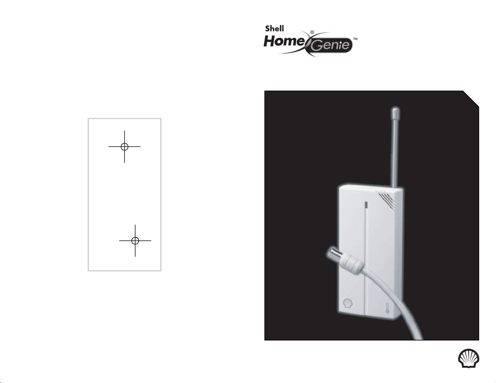
DRILLING TEMPLATE FOR WALL MOUNTING
TEMPERATURE SENSOR(S) ///
For wall mounting sensor(s), drill two holes using a 1/4” drill bit and the template below.
Insert supplied wall anchors into holes and secure sensor to wall with supplied screws.
Printers and copy machines can affect the scale of this template. Before drilling, compare this template
with the actual sensor by placing the template on the back of the sensor and observing if mounting holes
on sensor line up exactly with the drill holes on this template.
DRILL HOLES IN
THESE POSITIONS
TEMPERATURE SENSOR
Page 3
PRODUCT DESCRIPTION ///
The Shell HomeGenie™ Temperature Sensor senses temperature changes within
a range of 14ºF and 104ºF and can be set to notify you when the temperature falls outside
of your preferred range.
HIGH 104º F
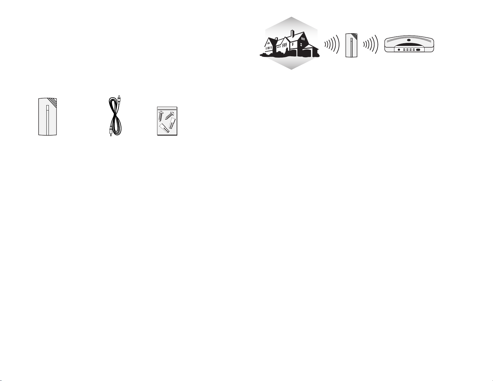
PACKAGE CONTENTS ///
■
(1) Shell HomeGenie™ Temperature Sensor
■
(1) External Temperature Probe
■
(1) Wall Mounting Kit
SHELL HOMEGENIE TEMPERATURE SENSOR
INSTALLATION ///
EXTERNAL TEMPERATURE PROBE WALL MOUNTING KIT
The Shell HomeGenie™ Temperature Sensor is constructed of UV resistant ABS plastic allowing
for indoor or sheltered outdoor use. The sensor works by monitoring ambient temperature. If the
temperature moves outside of the temperature range you specify, the sensor reports this to the
Motorola Gateway and an event is triggered.
NOTE: The Temperature Sensor cannot be used on metal doors, metal doorframes or other metal objects.
1. Peel the paper strip from the double-sided tape located on the back of the sensor.
You can also mount the sensor more securely using the screws in the wall mounting kit. Using the
drilling template on the back of the instruction guide, drill two small holes for the screws.
Affix the screws to any object leaving 1/16” space between the screw head and the object,
LOW 14º F
EXTERNAL TEMPERATURE PROBE
With the use of the External Temperature Probe you can extend the temperature sensitivity range of
the Temperature Sensor to between -40ºF and 140ºF (-40ºC and 60ºC). The probe attaches to the
Temperature Sensor, is submersible and is designed to monitor the temperature of both air and water.
A pool, aquarium, deep freezer, and/or baseboard radiator are just a few suggested places where you
can use your External Temperature Probe to monitor both ambient and water temperature.
HELPFUL HINTS ///
The Shell HomeGenie™ Temperature Sensor is suitable for indoor and outdoor use. Please bear in
mind the following points when choosing a mounting position:
■
The Temperature Sensor cannot be mounted on metal doors, metal door frames or metal objects.
■
Be sure to use 2-“AAA” alkaline batteries from a reliable manufacturer. Currently the sensor
does not support rechargeable NiCad or NiMH batteries. However, the sensor does have
power saving functionality.
■
You should periodically test the batteries by pushing the ‘discovery’ button located on the back
of the Temperature Sensor. If battery power is available the LED indicator will light.
FAQ’S ///
HOW FAR AWAY CAN THE SENSOR BE PLACED FROM THE MOTOROLA GATEWAY?
Typically 60 feet.
2. Mount the sensor onto the screws and slide down to lock into place
SETTING THE TEMPERATURE THRESHOLDS
With your Shell HomeGenie™ service, you can log in to your account and set either a rising or
a declining temperature threshold. You can also set both thresholds to create a temperature range,
that will trigger an event when the temperature moves beyond the set range. Temperature settings
can be easily changed from Fahrenheit (F) to Celsius (C) and have a sensitivity range between
14ºF and 104ºF (-10ºC and 40ºC).
CAN I PLACE THE SENSOR IN A DIFFERENT ROOM FROM THE MOTOROLA GATEWAY?
Yes, the sensor uses radio frequencies to communicate with the Motorola Gateway.
These frequencies can travel through objects such as walls, ceilings, and floors.
HOW LONG WILL THE BATTERY LAST?
The batteries are expected to last up to 12 months. This will depend on actual use and how often
the Temperature Sensor is triggered.
HOW MANY SENSORS CAN I USE WITH MY MOTOROLA GATEWAY?
The Motorola Gateway can support up to 20 sensors.
THE LED INDICATOR ON THE SENSOR IS NOT ON?
This indicates that the sensor has gone into hibernation mode to save battery power. It will wake up
when the sensor is triggered.
2I
Page 4

TECHNICAL SPECS ///
■
Attaches to vertcal flat surfaces (antenna must be pointing up)
■
Operates on 2-“AAA” Alkaline batteries
■
LED indicator when sensor is triggered
■
Test/Discover button
Typical Range Outdoors: 250 feet
Typical Range Indoors: 60 feet
Frequency Range: 418 MHz
APPROVALS ///
FCC ID NUMBER: OU4-XWS20T / IC: 4576A-XWS20T
STANDARDS
93/68/EEC, 89/336/EEC, BS EN 50082-1:1992, 73/23/EEC, EN60950:1992 CE
INSTRUCTIONS TO THE USER:
The user is cautioned that changes and modifications made to the equipment without the approval of manufacturer could void the user's
authority to operate this equipment.
This equipment has been tested and found to comply with the limits for a class B digital device, pursuant to part 15 of the FCC Rules.
These limits are designed to provide reasonable protection against harmful interference in a residential installation. This equipment
generates, uses and can radiate radio frequency energy and if not installed and used in accordance with the instructions, may cause
harmful interference to radio communications. However, there is no guarantee that interferences will not occur in a particular installation.
If this equipment does cause harmful interference to radio or television reception, which can be determined by turning the equipment off
and on, the user is encouraged to try to correct the interference by one or more of the following measures:
• Reorient or relocate the receiving antenna.
• Increase the separation between the equipment and receiver.
• Connect the equipment into an outlet on a circuit different from that to which the receiver is connected.
• Consult the dealer or an experienced radio/TV technician for help.
CE directive 93/68/EEC, EMC directive 89/336/EEC, LV directive 73/23/EEC.
This class B digital apparatus complies with Canadian ICES-003.
The term “IC:” before the certification/registration number only signifies that the Industry Canada technical specifications were met.
Operation is subject to the following two conditions: (1) this device may not cause interference, and (2) this device must accept any
interference, including interference that may cause undesired operation of the device.
43
 Loading...