

Page 1
XAC Automation Corporation
886-3-577-2738
www.xac.com.tw
The above information is the exclusive intellectual property of XAC Automation Corporation
and shall not be disclosed, distributed or reproduced without permission of XAC Automation
Corporation.
XAC AUTOMATION CORP. shall not be held liable for technical and editorial omissions or
errors made herein; nor for incidental or consequential damages resulting from the furnishing,
performance or use of his material.
This document contains proprietary information protected by copyright. All rights are reserve.
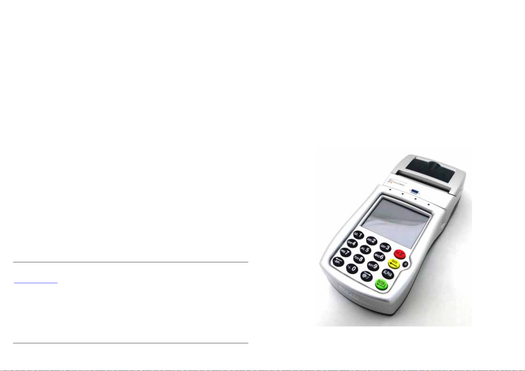
P
ORTABLE TERMINAL
FD-400GT
INSTALLATION GUIDE
Page 2
Warning: If the device, FD400GT, is used without the detachable privacy shield, the
following criteria needs to be met by the Installed Environment of the PED for
complying with the PCI privacy screen design requirement:
A. Positioning of the PED on the check-stand in such way as to make visual
observation of the PIN-entry process infeasible.
Visual shields designed into the check-stand.
Position the PED so that it is angled in such a way to make PIN spying
difficult.
B. Pop-up (temporary) privacy shield attached to the PED mounting stand.
Consumer (through education & prompting) or merchant would put the shield
in place during PIN entry.
C. Installing PED on an adjustable stand that allows consumers to swivel the
terminal sideways and/or tilt it forwards/backwards to a position that makes
visual observation of the PIN-entry process difficult.
D. Positioning of in-store security cameras such that the PIN-entry keypad is not
visible.
E. Instructing the cardholder regarding safe PIN-entry, done with a combination of:
Signage on the PED.
Prompts on the display, possibly with a "click-through" screen.
Potentially literature at the point of sale.
A logo for safe PIN-entry process.
1.
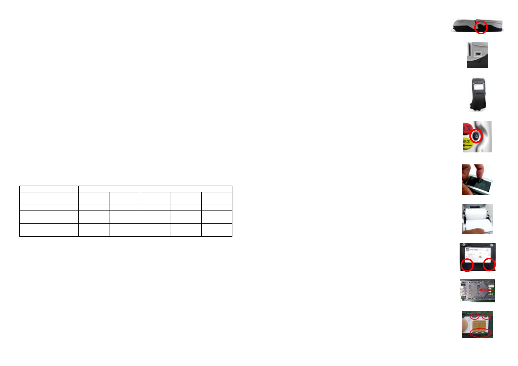
BEFORE STARTING
There are two holes under a plastic cover on the left side of
terminal (Figure 1). One is a power jack; the other is an USB
Figure 1
programmable port (Figure 2). Rechargeable battery is on the
back side of terminal (Figure 3).
Adapter spec:
DELTA_ADP-36JH B
Input: 100-240Vac, 50/60Hz 1A Output: 12Vdc, 3A
Operating Temperature: 0
o
C to 40oC
Figure 2
Battery pack: CHENG UEI / FD400 7.4V, 2.3Ah
RTC battery spec: 3V, CR2032
Caution: The cover (Figure 3) shall be provided with a means
to keep it closed during normal operation.
Caution: Risk of explosion if the battery is replaced by an
Figure 3
incorrect type. Please dispose of used battery according to the
instructions.
Warning: A shielded-type power cord is required in order to
meet FCC emission limits and also to prevent interference to
the nearby radio and television reception. It is essential that
only the supplied power cord be used.
Figure 4
Table A1: Matrix of Observation Corridors and PIN Protection Method
Method Cashier
PED Stand A M H L L L
PED Stand B H H H L M
Check-Stand A L M M L H
Check-Stand B H H M H H
Customer Instruction H* H* H* H* H*
z Customer Instruction methods are less repeatable and therefore should be used in
combination with other methods. L = low, M = medium, H = high.
Observation Corridors
Customers
in Queue
Customers
Elsewhere
On-Site
Cameras
Remote
Cameras
2. POWER ON THE TERMINAL
Install the battery, or plug the power cord into the power jack
and plug the power adapter into a 120-volt electrical outlet or
into a surge suppressor (recommended) after the power cord is
connected to the power adapter. Press the power button at the
front of device (Figure 4) until the system is booted up.
3. LOADING THE PAPER
Gently pop the printer cover’s latch to open the cover (Figure
5); then lift the cover.
Load a roll of thermal paper (Appleton 1012 recommended)
into the printer (Figure 6). Load it so that the print-side of the
paper will feed out facing the operator.
Close the cover by pressing down evenly on both side tabs, or
by pressing on the center of the printer cover.
Use the serrated bar to tear off any excess paper.
4. INSTALLING THE SIM CARD
SIM slots are located above the battery charger. Before insert
the SIM card, please turn off the device and remove the cover
by loosen the two screws (Figure 7).
Push one SIM gate leftward (Figure 8), open it and insert the
SIM card in the slot. Make sure that the card is located
correctly (Figure 9). Close the SIM gate and pull rightward to
lock it. Finally, Screw the cover back.
Figure 5
Figure 6
Figure 7
Figure 8
Figure 9
Page 3

5. USING THE MAGNETIC CARD READER
Find the reader slot in the middle of surface. Swipe card through slot
from left to right or the opposite direction with stripe lies down and
facing the display (Figure 10).
6. USING THE CONTACTLESS CARD READER
Contactless reader antenna is around the display and PIN pad. It will
light up with blue color signal when FD400GT is powered on and that
means reader is working normally.
Put contactless card to approach the antenna of card reader (Figure 11)
for reading the card data during transaction.
7. USING THE KEY PAD
To enter numbers or letters, simply press the appropriate key. For
example, to type the letter A: Press [ALPHA], then [A] (the Void key)
(Figure 12).
Caution: For body worn operation, this terminal will keep away 20cm from the body
in order to meet the FCC RF exposure guidelines
Caution: Use only shielded signal cables to connect I/O devices to this equipment.
You are cautioned that changes or modifications not expressly approved by the
party responsible for compliance could void your authority to operate the equipment.
This device complies with Part 15 of the FCC Rules. Operation is subject to the
following two conditions: (1) This device may not cause harmful interference, and (2)
this device must accept any interference received, including interference that may
cause undesired operation.
Federal Communication Commission Interference Statement
This equipment has been tested and found to comply with the limits for a Class A
digital device, pursuant to Part 15 of the FCC Rules. These limits are designed to
provide reasonable protection against harmful interference in a residential
installation. This equipment generates, uses and can radiate radio frequency energy
and, if not installed and used in accordance with the instructions, may cause harmful
interference to radio communications. However, there is no guarantee that
interference will not occur in a particular installation. If this equipment does cause
harmful interference to radio or television reception, which can be determined by
turning the equipment off and on, the user is encouraged to try to correct the
interference by one of the following measures:
- Reorient or relocate the receiving antenna.
- Increase the separation between the equipment and receiver.
- Connect the equipment into an outlet on a circuit different from that to which the
receiver is connected.
- Consult the dealer or an experienced radio/TV technician for help.
Figure 10
Figure 11
Figure 12
FCC Caution: Any changes or modifications not expressly approved by the party responsible for
compliance could void the user's authority to operate this equipment.
IMPORTANT NOTE:
FCC Radiation Exposure Statement:
This equipment complies with FCC radiation exposure limits set forth for an uncontrolled environment.
This equipment should be installed and operated with minimum distance 20cm between the radiator &
your body. This transmitter must not be co-located or operating in conjunction with any other antenna
or transmitter.
Industry Canada Statement
This device complies with RSS-210 of the Industry Canada Rules. Operation is subject to the following
two conditions:
(1) this device may not cause interference and
(2) this device must accept any interference, including interference that may cause undesired operation
of the device
Ce dispositif est conforme à la norme CNR-210 d'Industrie Canada applicable aux appareils radio
exempts de licence. Son fonctionnement est sujet aux deux conditions suivantes:
(1) le dispositif ne doit pas produire de brouillage préjudiciable, et
(2) ce dispositif doit accepter tout brouillage reçu, y compris un brouillage susceptible de provoquer un
fonctionnement indésirable.
IMPORTANT NOTE: IC Radiation Exposure Statement:
This equipment complies with IC radiation exposure limits set forth for an uncontrolled environment.
This equipment should be installed and operated with minimum distance 20cm between the radiator &
your body.
NOTE IMPORTANTE: (Pour l'utilisation de dispositifs mobiles)
Déclaration d'exposition aux radiations:
Cet équipement est conforme aux limites d'exposition aux rayonnements IC établies pour un
environnement non contrôlé. Cet équipement doit être installé et utilisé avec un minimum de 20 cm de
distance entre la source de rayonnement et votre corps.
Warning: This is a Class A product. In a domestic environment this product may cause radio
interference in which case the user may be required to take adequate measures.
 Loading...