

Federal Communications Commission (FCC)
Statement
FIRST DATA CORPORATION
This Equipment has been tested and found to comply with
the limits for a Class B digital device, pursuant to part 15
of the FCC Rules. These limits are designed to provide
reasonable protection against harmful interference when
the equipment is operated in a commercial environment.
This equipment generates, uses, and can radiate radio
frequency energy and, if not installed and used in
accordance with the instruction manual, may cause
harmful interference to radio communication.
Operation of this equipment in a residential area is likely
to cause harmful interference in which case the user will be
required to correct the interference at his own expense.
First Data Corporation
c/o Tasq Technology
http://www.firstdata.com/
Printed in the United States of America.
© Copyright 2009 First Data Corporation. All rights reserved.
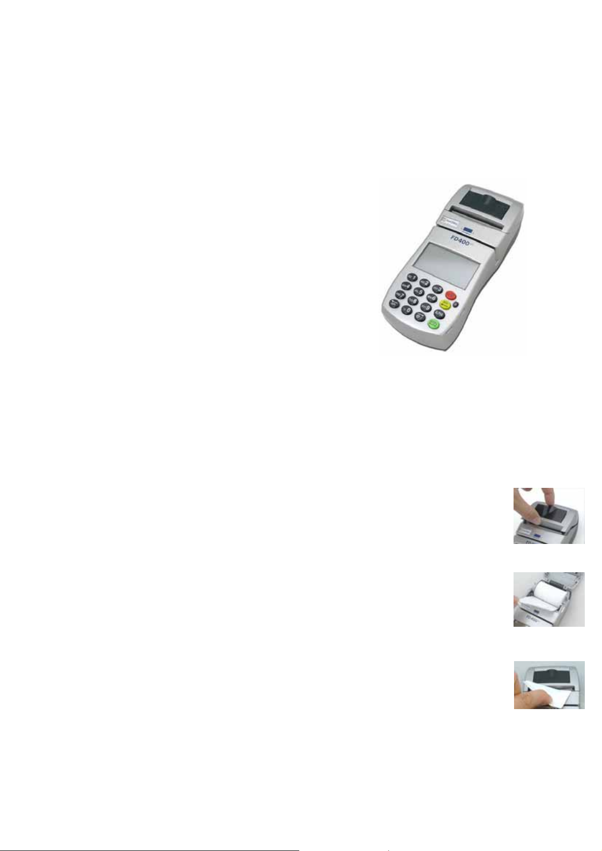
P
ORTABLE TERMINAL
FD-400
I
NSTALLATION GUIDE
eTi
Visual shields designed into the check-stand.
Position the PED so that it is angled in such a way
to make PIN spying difficult.
B. Pop-up (temporary) privacy shield attached to the PED
mounting stand. Consumers (through education &
prompting) or merchant would put the shield in place
during PIN entry.
C. Installing PED on an adjustable stand that allows
consumers to swivel the terminal sideways and/or tilt
it forwards/backwards to a position that makes visual
observation of the PIN-entry process difficult process
infeasible.
Visual shields designed into the check-stand.
Position the PED so that it is angled in such a way
to make PIN spying difficult.
D. Positioning of in-store security cameras such that the
PIN-entry keypad is not visible. Instructing the
cardholder regarding safe PIN-entry, done with a
combination of:
Signage on the PED.
Prompts on the display, possibly with a
"click-through" screen.
Potentially literature at the point of sale.
A logo for safe PIN-entry process.
5 2
Caution: Risk of explosion if the battery
is replaced by an incorrect type. Please
dispose used battery according to the
local regulations.
“Caution: For continued protection
against fire, replace only with same type
same rating fuse.” Marking is located on
the enclosure of cigarette lighter plug or
located on the input cable near cigarette
lighter plug. Fuse rating (voltage and
ampere) shall also be marked on the
enclosure of cigarette lighter plug near
the fuse.
Caution: For hand held operation, this
terminal will keep away 20cm from the
body in order to meet the FCC RF
exposure guidelines.
LOADING THE PAPER
Pop the printer cover’s latch to open the
cover (Figure 5); then lift the cover. Load
a roll of paper (Appleton 1012 is
recommended) into the printer (Figure
6). The print-side of the paper will feed
out facing the operator.
Close the cover and tear off any excess
paper (Figure 7). The printer is now
ready to use.
Figure 5
Figure 6
Figure 7
POWER ON TERMINAL
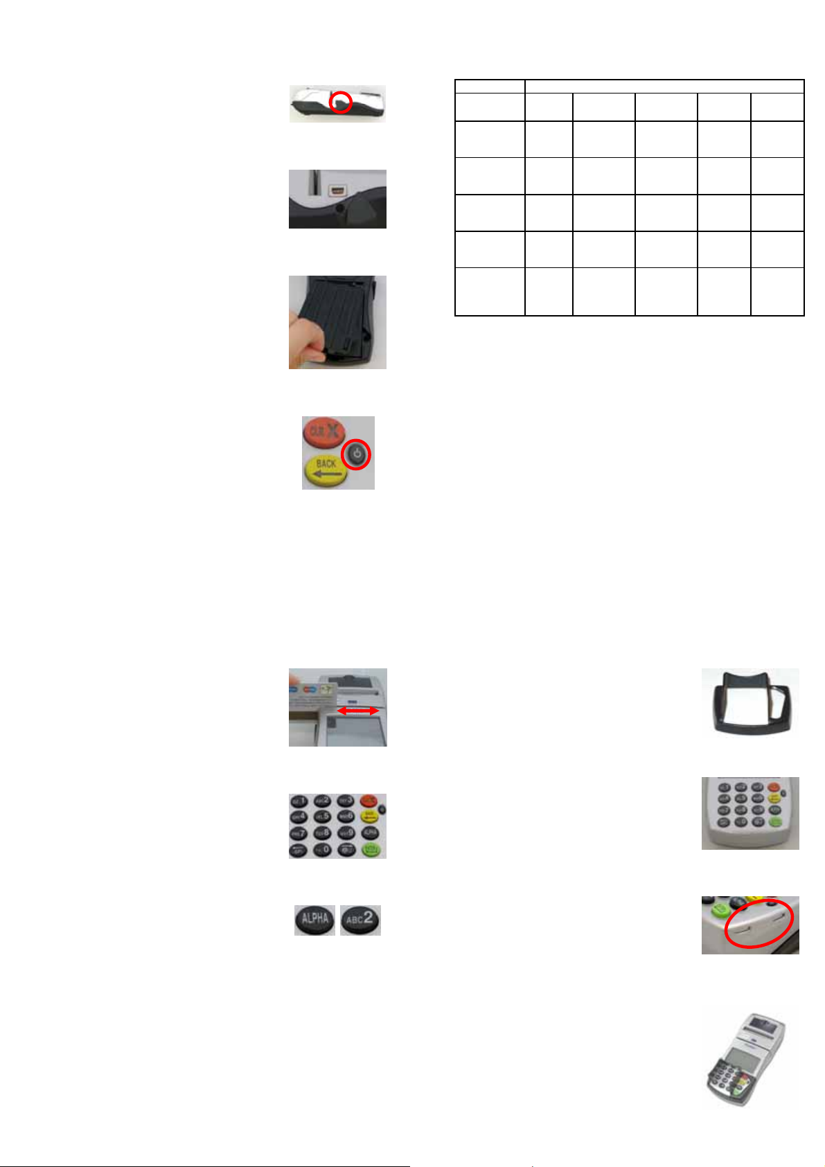
There are two connections under a
plastic cover on the left side of terminal
(Figure 1). The bottom is power input;
the other is a USB port for devices to
connect to terminal (Figure 2).
Adapter spec:
LI SHIN INT. / LSE0107A1240
Input: 100-240Vac, 50/60Hz 1A
Output: 12Vdc, 3.33A
Operating Temperature:
o
C to 40oC
0
Battery pack:
CHENG UEI / FD-400 7.4V, 2.3Ah
Car Charger:
EDAC POWER ELECRONICS CO.,
LTD. / ED1025
Input: 11-16Vdc, 5A
Output: 12Vdc, 2.5A
Rechargeable battery is at the bottom of
terminal (Figure 3).
Figure 1
Figure 2
Figure 3
Table A1: Matrix of Observation Corridors and PIN Protection
Methods
Method Cashier
PED Stand
A
PED Stand B H H H L M
Check-Stand
A
Check-Stand
B
Customer
Instruction
* Customer Instruction methods are less repeatable and therefore should be
used in combination with other methods. L = low, M = medium, H = high.
M H L L L
L M M L H
H H M H H
H* H* H* H* H*
Observation Corridors
Customers Customers On-Site Remote
in Queue Elsewhere Cameras Cameras
Caution: The cover (Figure 3) shall be
provided with a means to keep it closed
during normal operation.
Plug the power cord or install the
battery, press the power button on the
front to power on it (Figure 4).
1
USING THE CARD READER
The reader slot is located at of terminal.
Swipe card through slot in left to right
or the opposite direction with stripe
face to us (Figure 8).
USING THE KEYPAD
The keypad allows you to select
transaction types and enter information.
It has 16 keys can be used to select
numbers, letters, and to enter data
(Figure 9).
To enter numbers or letters, simply
press the appropriate key. For example,
to type the letter A, press [ALPHA],
and then [A] (the Void key). (Figure 10)
Warning:
A shielded-type power cord is required
in order to meet FCC emission limits
and also to prevent interference to the
nearby radio and television reception.
Use only the power cord supplied.
Caution: Use only shielded signal
cables to connect I/O devices to this
equipment. You are cautioned that
changes or modifications not expressly
approved by the party responsible for
3
Figure 4
Figure 8
Figure 9
Figure 10
6
compliance could void your authority
to operate the equipment.
INSTALLING PRIVACY SHIELD
The privacy shield of the FD-400eTi
shows as Figure 11.
There are four slots along the perimeter
(Figure 12). Lock the privacy shield
Figure 11
around on the slots (Figure 13).
When the privacy shield is installed, the
keypad is separated into two part;
number keys are protected within the
shield (Figure 14).
Warning:
Figure 12
If the device, FD-400eTi, is used
without the detachable privacy shield,
the following criteria needs to be met
by the Installed Environment of the
PED for complying with the PCI
Figure 13
privacy screen design requirement:
A. Positioning of the PED on the
check-stand in such way as to make
visual observation of the PIN-entry
process infeasible.
Figure 14
4

Federal Communications Commission Notice
This device complies with part 15 of the FCC Rules. Operation is subject to the foll
owing two conditions:
(1) This device may not cause harmful interference, and
(2) this device must accept any interference received, including interference that m
ay cause undesired operation.
This equipment has been tested and found to comply with the limits for a Class B d
igital device, pursuant to Part 15 of the FCC Rules. These limits are designed to pro
vide reasonable protection against harmful interference in a residential installation.
This equipment generates, uses, and can radiate radio frequency energy and, if no
t installed and used in accordance with the instructions, may cause harmful interfe
rence to radio communications. However, there is no guarantee this equipment do
es not cause harmful interference to radio or TV reception. This can be determined
by turning the equipment on and off. The user is encouraged to try to correct the in
terference by one or more of the following measures:
_ Reorient or relocate the receiving antenna.
_ Increase the separation between the equipment and receiver.
_ Connect the equipment into an outlet on a circuit different from that to whi
ch the receiver is connected.
_ Consult the dealer or an experienced radio or television technician for help.
NOTE: THE MANUFACTURER IS NOT RESPONSIBLE FOR ANY RADIO OR TV
INTERFERENCE CAUSED BY UNAUTHORIZED MODIFICATIONS TO THIS
EQUIPMENT. SUCH MODIFICATIONS COULD VOID THE USERS
AUTHORITY TO OPERATE THE EQ UIPMENT.
FCC Radiation Exposure Statement
This equipment complies with FCC radiation exposure limits set forth for an
uncontrolled environment . End users must follow the specific operating
instructions for satisfying RF exposure compliance. To maintain compliance with
FCC RF exposure compliance requirements, please follow operation instruction as
documented in this manual.
For hand-held or desktop operation only. This PORTABLE TERMINAL meets
FCC RF exposure guidelines when used in hand-held or desktop operation. The
antenna should be operated minimum distance of 20 centimeters between the human
body.
 Loading...