

Page 1
Warning:
A shielded-type power cord is required in order to meet FCC emission
limits and also to prevent interference to the nearby radio and television
reception. It is essential that only the supplied power cord be used.
Use only shielded signal cables to connect I/O devices to this
equipment.
You are cautioned that changes or modifications not expressly
approved by the party responsible for compliance could void your
authority to operate the equipment."
First Data Corporation
c/o Tasq Technology
800-835-3362 Ext. 0
http://www.firstdata.com/
Printed in the United States of America.
© Copyright 2006 First Data Corporation. All rights reserved.
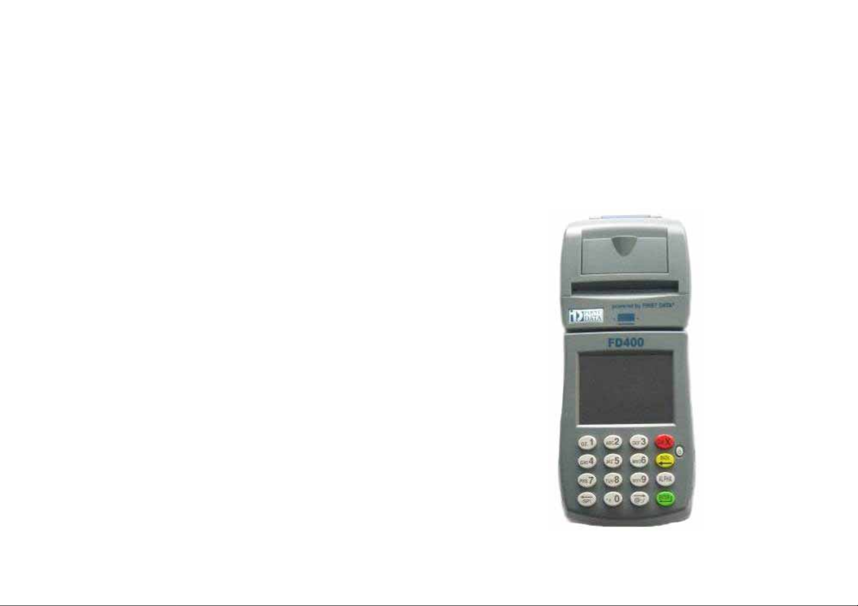
ORTABLE TERMINAL
P
FD-400
NSTALLATION GUIDE
I
© 2007 First Data Corporation.
Page 2
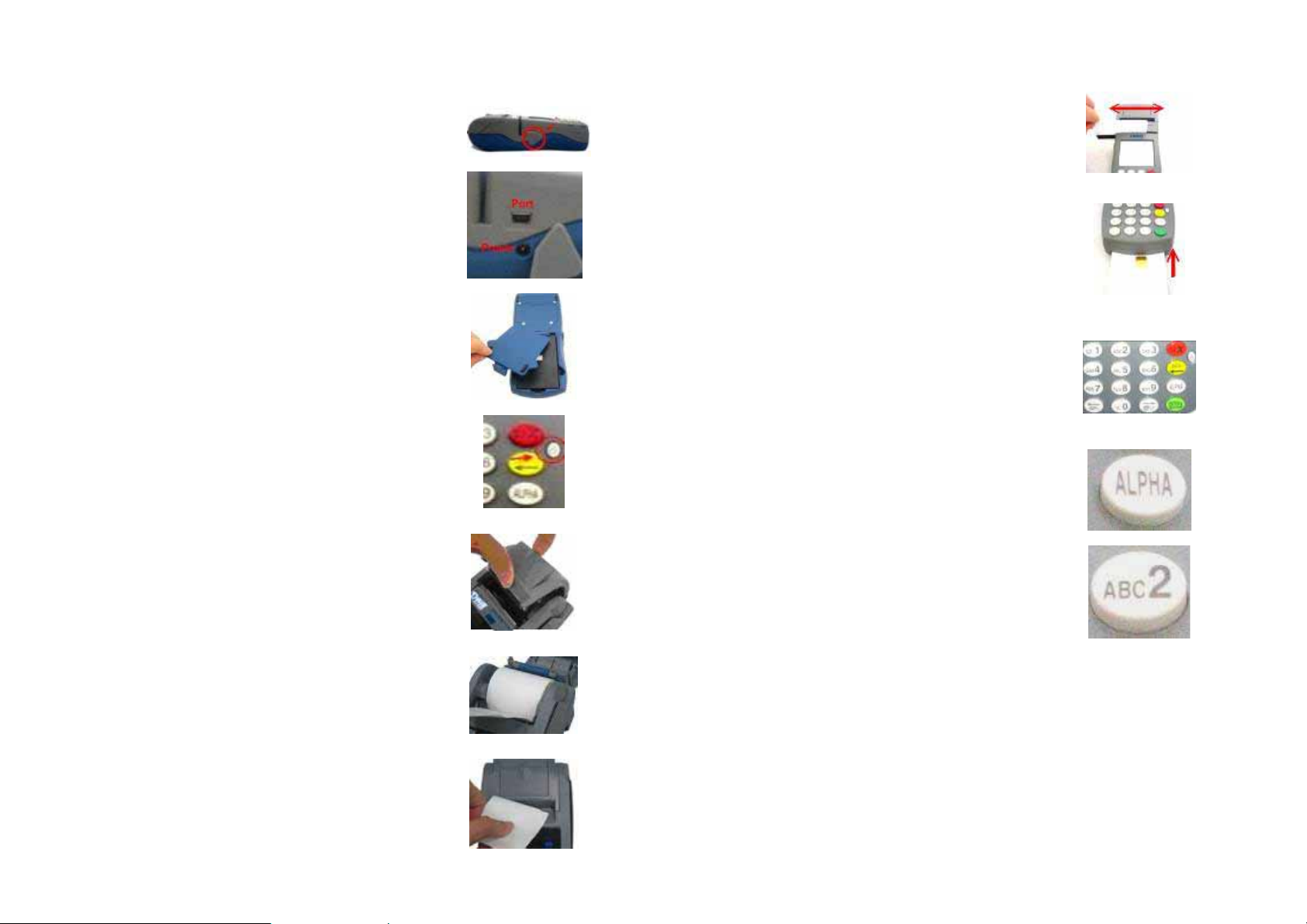
1. POWER ON TERMINAL
3. USING THE CARD READER
There are two holes under a plastic cover on the
right side of terminal (Figure 1).
One is power input, another is a port for devices
connected to terminal (Figure 2). (Adapter Input:
100-240V, 50/60Hz 1A; Output: 12V, 3.33A)
Rechargeable battery is on the back side of terminal
(Figure 3). (Lithium ion battery pack: 7.4V, 2.2A)
After plugged power cord or installed the battery,
press the power button on the front to power on it
(Figure 4).
Caution: Risk of explosion if the battery is replaced
by an incorrect type. Please dispose of used battery
according to the instructions.
Environment:
Operating Temperature: 0°C to 40°C
Storage Temper ature: - 20°C to 60°C
2. LOADING THE PAPER
Pop the printer cover’s latch to open the cover
(Figure 5); then lift the cover.
Load a roll of paper (Appleton 1012 recommended)
into the printer (Figure 6). The print-side of the
paper will feed out facing the operator.
Close the cover and tear off any excess paper
(Figure 7).
The printer is now ready to use.
Figure 1
Figure 2
Figure 3
Figure 4
Figure 5
Figure 6
Find the reader sl ot in the middle of surface. Swipe
card through slot in left to right or the opposite
direction with stripe face to us (Figure 8).
Find the reader slot on the bottom. Insert smart card
into slot with IC chip to face up (Figure 9).
4. USING THE KEY PAD
The keypad allows you to select transaction types
and enter information. Its 16 keys can be used to
select numbers, letters, and to enter data (Figure 10).
To enter numbers or letters, simply press the
appropriate key. For example, to type the letter A,
press [ALPHA], then [A] (the Void key) (Figure 11)
Figure 8
Figure 9
Figure 10
Figure 11
Caution: For body worn operation, this terminal
will keep away 20cm from the body in order to
meet the FCC RF exposure guidelines
Figure 7
Page 3

Federal Communications Commission Notice
FCC Radiation Exposure Statement
This device complies with part 15 of the FCC Rules. Operation is subject to the foll
owing two conditions:
(1) This device may not cause harmful interference, and
(2) this device must accept any interference received, including interference that m
ay cause undesired operation.
For hand-held or desktop operation only. This PORTABLE TERMINAL meets
This equipment has been tested and found to comply with the limits for a Class B d
FCC RF exposure guidelines when used in hand-held or desktop operation.
igital device, pursuant to Part 15 of the FCC Rules. These limits are designed to pro
vide reasonable protection against harmful interference in a residential installation.
This equipment generates, uses, and can radiate radio frequency energy and, if no
t installed and used in accordance with the instructions, may cause harmful interfe
rence to radio communications. However, there is no guarantee this equipment do
es not cause harmful interference to radio or TV reception. This can be determined
by turning the equipment on and off. The user is encouraged to try to correct the in
terference by one or more of the following measures:
z Reorient or relocate the receiving antenna.
z Increase the separation between the equipment and receiver.
z Connect the equipment into an outlet on a circuit different from that to whi
ch the receiver is connected.
z Consult the dealer or an experienced radio or television technician for hel
p.
This equipment complies with FCC radiation exposure limits set forth for an
uncontrolled environment . End users must follow the specific operating
instructions for satisfying RF exposure compliance. To maintain compliance with
FCC RF exposure compliance requirements, please follow operation instruction as
documented in this manual.
NOTE: THE MANUFACTURER IS NOT RESPONSIBLE FOR ANY RADIO OR TV
INTERFERENCE CAUSED BY UNAUTHORIZED MODIFICATIONS TO THIS
EQUIPMENT. SUCH MODIFICATIONS COULD VOID THE USERS
AUTHORITY TO OPERATE THE EQUIPMENT.
 Loading...