

Page 1
Federal Communication Commission Interference Sta t em ent
This equipment has been tested and found to comply with the limits for a Class B digital device,
pursuant to Part 15 of the FCC Rules. These limits are designed to provide reasonable protection
against harmful interference in a residential installation. This equipment generates, uses and can
radiate radio frequency energy and, if not installed and used in accordance with the instructions,
may cause harmful interference to radio communications. However, there is no guarantee that
interference will not occur in a particular installation. If this equipment does cause harmful
interference to radio or television reception, which can be determined by turning the equipment
off and on, the user is encouraged to try to correct the interference by one of the following
measures:
- Reorient or relocate the receiving antenna.
- Increase the separation between the equipment and receiver.
- Connect the equipment into an outlet on a circuit different from that
to which the receiver is connected.
- Consult the dealer or an experienced radio/TV technician for help.
FCC Caution: Any changes or modifications not expressly approved by the party responsible for
compliance could void the user's authority to operate this equipment.
This device complies with Part 15 of the FCC Rules. Operation is subject to the following two
conditions: (1) This device may not cause harmful interference, and (2) this device must accept any
interference received, including interference that may cause undesired operation.
Underwriters Laboratories Inc. (“UL”) has not tested the performance or reliability of
the security of Radio Frequency Identification (RFID) or other aspects of this product. UL has only
tested for fire, shock and/or casualty hazards as outlined in UL's Standard(s) for Safety of U.S.
and Canadian (Bi-National) Standard for Information Technology Equipment - Safety - Part 1:
General Requirements, CAN/CSA-C22.2 No. 60950-1-03 * UL 60950-1, First Edition. UL
Certification does not cover the performance or reliability of the security or signaling aspects of
this product. UL MAKES NO REPRESENTATIONS, WARRANTIES OR CERTIFICATIONS
WHATSOEVER REGARDING THE PERFORMANCE OR RE LIABILITY OF ANY SECURITY OR
SIGNALING RELATED FUNCTIONS OF THIS PRODUCT.
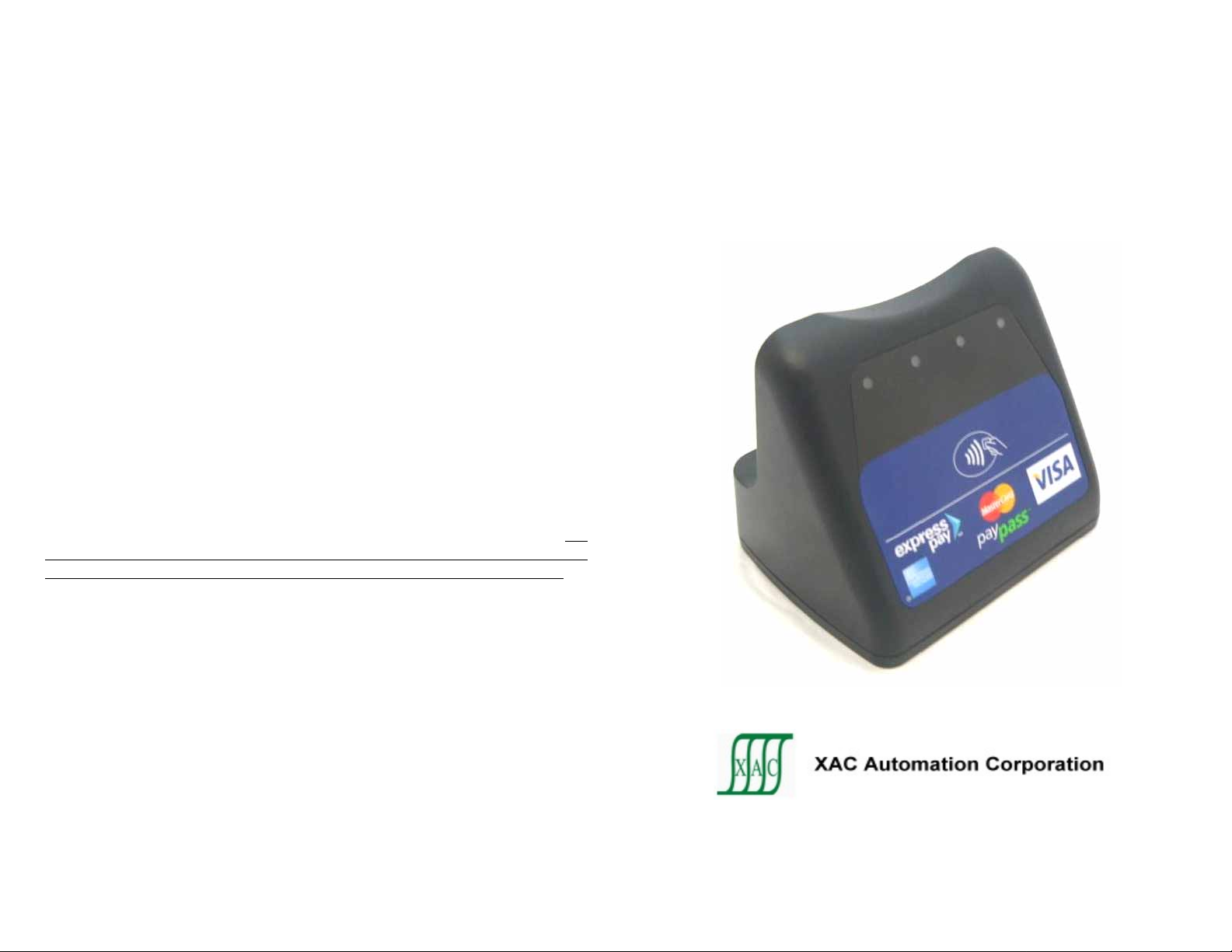
XAC Automation Corporation
886-3-577-2738
www.xac.com.tw
The above information is the exclusive intellectual property of XAC Automation
Corporation and shall not be disclosed, distributed or reproduced without permission
of XAC Automation Corporation.
XAC CONTACTLESS READER
INSTALLATION GUIDE
Page 2
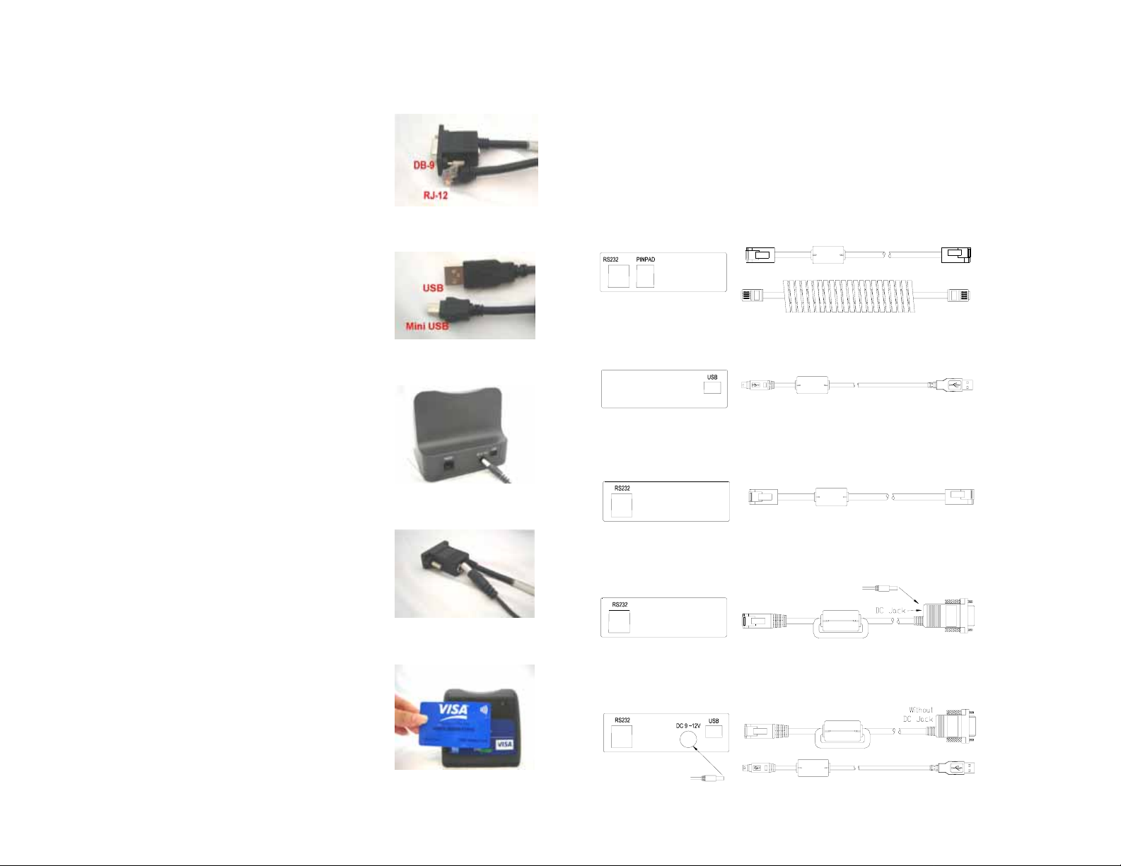
1. READER DEVICE SETUP
Contactless Reader rear panel has the accordingly
communication port. Insert the modular plug on the
connecting cable to the modular jack on the rear of the
Cradle unit.
Plug the other end of this cable (DB-9 or USB) to the host
(PC or terminal), See Figure 1 and 2. For different model
type, please insert the round connector plug from the
power adapter to the port at the back of the DB-9 serial
connector or device. Plug the power adapter to the AC
wall outlet. See Figure 3 and 4.
2. TEST TRANSACTION
A test transaction should be performed upon installation
to ensure trouble-free operation of the device in Figure 5.
3. MAINTENANCE
Stringent quality-control standards are followed in
manufacturing all reader devices. Numerous
tests are performed on each unit before leaving the
factory to ensure quality and reliability.
4. RETURNING READER DEVICE
If you need to return your device for service or
replacement, contact your service provider or sales
representative for instructions.
Note: Do not try to service, repair or adjust the device in
any way; doing so will void your warranty.
Figure 1
Figure 2
Figure 3
Figure 4
Figure 5
5. CONTACTLESS READER DEVICE
MODEL TYPE
According to Customer’s implementation requirement,
XAC contactless reader supports five type connecting
modes as below.
Model 1:
Membrane P/N 202894000
RS232(POE) to LCTT/MTT with
Pinpad support w/o power adaptor
Model 2:
Membrane P/N 202819000
Standalone USB to LCTT/MT
or PC w/o power adaptor
Model 3:
Membrane P/N 202820000
Standalone RS232(POE) to LCTT/MTT
w/o power adaptor
Model 4:
Membrane P/N 202820000
Standalone RS232(POE) to PC
with power adaptor
6P6C
4P4C
To cradle
Mini usb
To cradle
6P6C
To cradle
Plug of Power adapter
6P6C
To cradle
CABLE 1 P/N 262197566
CABLE 2 P/N 262051566
CABLE P/N 262052566
CABLE P/N 262197566
CABLE P/N 262198566
6P6C(Offset key)
To host
To pinpad
USB plug A
To host or PC
6P6C(Offset key)
To host
DB9 Female
To PC
Model 5:
Membrane P/N 202818000
Standalone USB and RS232(POE)
to PC with power adaptor
Plug of Power adapter
6P6C
Mini usb
To cradle
CABLE P/N 262200566
CABLE P/N 262052566
DB9 Female
USB plug A
To PC
 Loading...