

Page 1
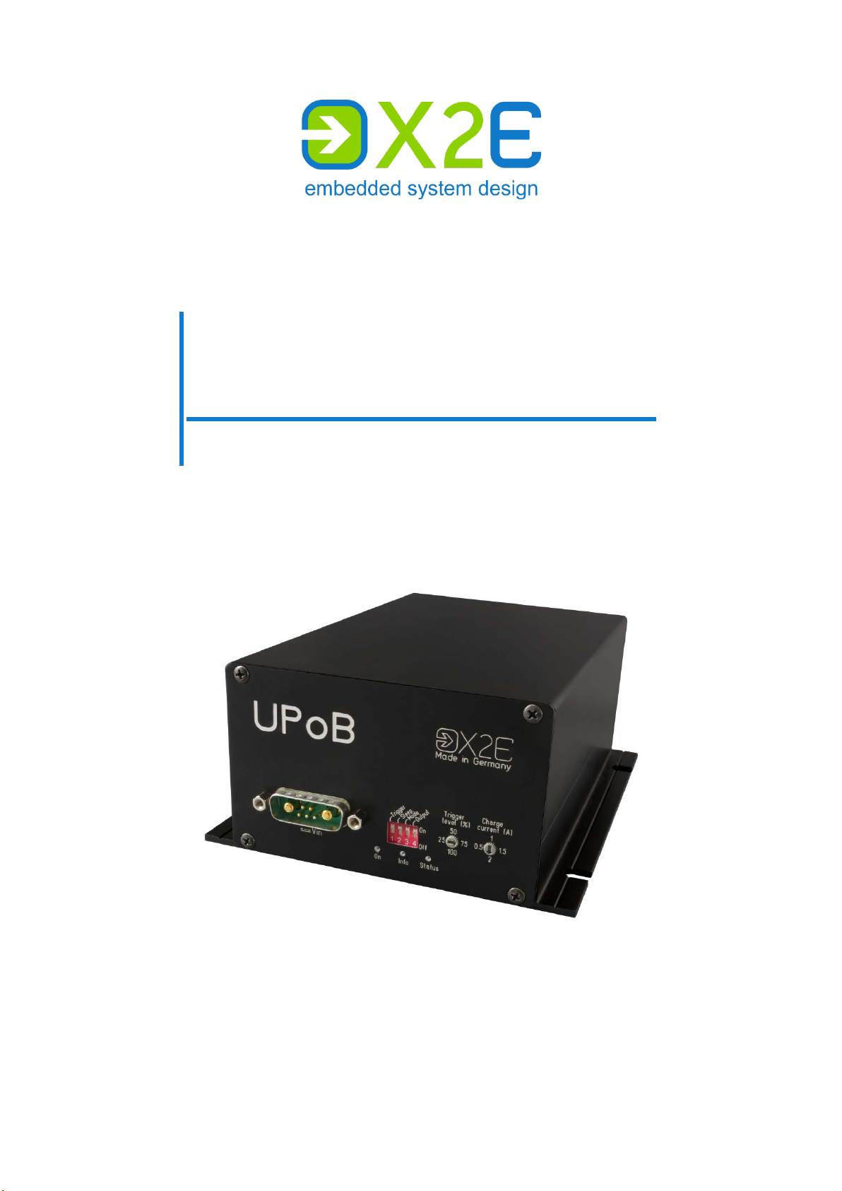
UPoB
Universal Power Brid ge
User Manual
Version: 1.6 / April 2019
Page 2

© 2019 X2E GmbH
This user manual is protected by copyright; all usual rights reserved. Reproduction of this user manual, even in
part, is only permitted with the approval of X2E GmbH. Any infringement will result in liability for damages and
may result in criminal prosecution.
All product names and brands used in this user manual are the property of their respective owners.
Page 3

User Manual UPoB
Table of contents
Introduction ............................................................................................. 4
Intended use ............................................................................................ 4
Delivery contents ..................................................................................... 4
General safety instructions ...................................................................... 5
Product overview..................................................................................... 6
Identification ............................................................................................. 6
Block diagram .......................................................................................... 7
Connections and controls ........................................................................ 8
Installation ............................................................................................. 15
Mounting ................................................................................................ 15
Connecting ............................................................................................. 15
Firmware update ................................................................................... 17
Cleaning ................................................................................................ 18
Repair ................................................................................................... 18
Disposal ................................................................................................ 18
Appendix ............................................................................................... 19
Technical specifications ......................................................................... 19
COM breakout cable .............................................................................. 20
Discharge times ..................................................................................... 21
Thresholds ............................................................................................. 22
Status messages ................................................................................... 24
3
Page 4

User Manual UPoB
Introduction
Intended use
The UPoB is an automotive universal power bridge that protects the connected system, such
as a X
to override the fluctuations for their duration of time. In case of a complete power f ailure, a
minimal voltage level is maintained until the connected system is shut down safely.
The UPoB is designed for industrial areas and must not be used in residential areas.
You may only operate the UPoB within the scope of the technical specifications provided in
this user manual. Additionally, the use in hazardous areas is not allowed.
Delivery contents
ORAYA data logger, against voltage fluctuations and power failures. The device is able
UPoB (Universal Power Bridge)
power cable
COM breakout cable
user manual
USB driver
Check to ensure that the delivery is complete and all hardware components are in sound
condition. If the delivery is incomplete or supplied components are damaged, contact X2E
immediately. Do not use damaged components.
4
Page 5
User Manual UPoB
Damages to the UPoB or the power cable can result in electric shock.
Excessive vibrations, dirt or liquids may result in malfunction or destruction
Electronic components can be destroyed by electrostatic discharge.
General safety instructions
The UPoB is only intended for use by qualified personnel. Read the user manual and especially this chapter thoroughly before operating.
CAUTION
Electric shock due to damaged components
Check all components regularly for damages.
Only connect the UPoB if all components are undamaged.
CAUTION
Device damage due to vibrations, dirt or liquids
of the UPoB.
Avoid exposing the UPoB to excessive vibrations, dirt or liquids.
Keep the UPoB clean, especially plugs and sockets to ensure a reli-
able contact.
Never open the UPoB.
CAUTION
Device damage due to electrostatic discharge
Avoid touching connectors and connector pins.
Ground yourself before carrying the UPoB in your hands.
Operate the UPoB in an ESD-compliant environment.
5
Page 6

User Manual UPoB
Product overview
Identification
The identification plate and the buffer capacity label are located on the bottom side of the
UPoB.
The identification plate contains information about:
device type
serial number
configuration
date of manufacture / last modification
Configuration consists of three blocks:
product ID
product variant
hardware revision
This user manual applies to the Universal Power Bridge in hardware version 0302 and firmware version 000307.
This label indicates the total capacitance of the integrated capacitors.
6
Page 7
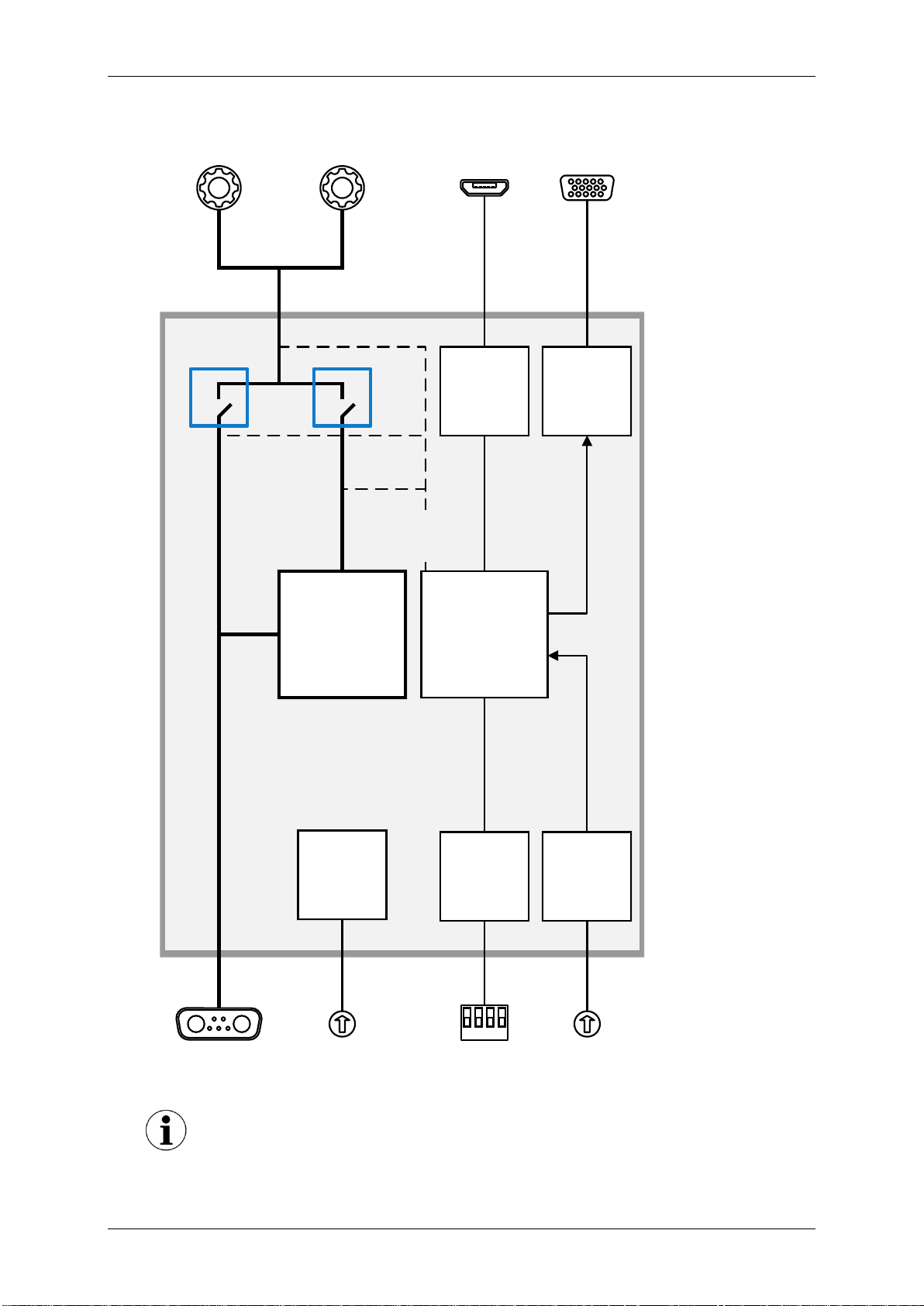
User Manual UPoB
Capacitors
Charge
current
Config
Micro-
controller
Trigger
level
Service
Monitor
4321
Normal
mode
Bridge
mode
COM
Acoustic signals on mode change
Block diagram
The UPoB indicates changes between normal mode and bridge mode by
acoustic signals.
7
Page 8
User Manual UPoB
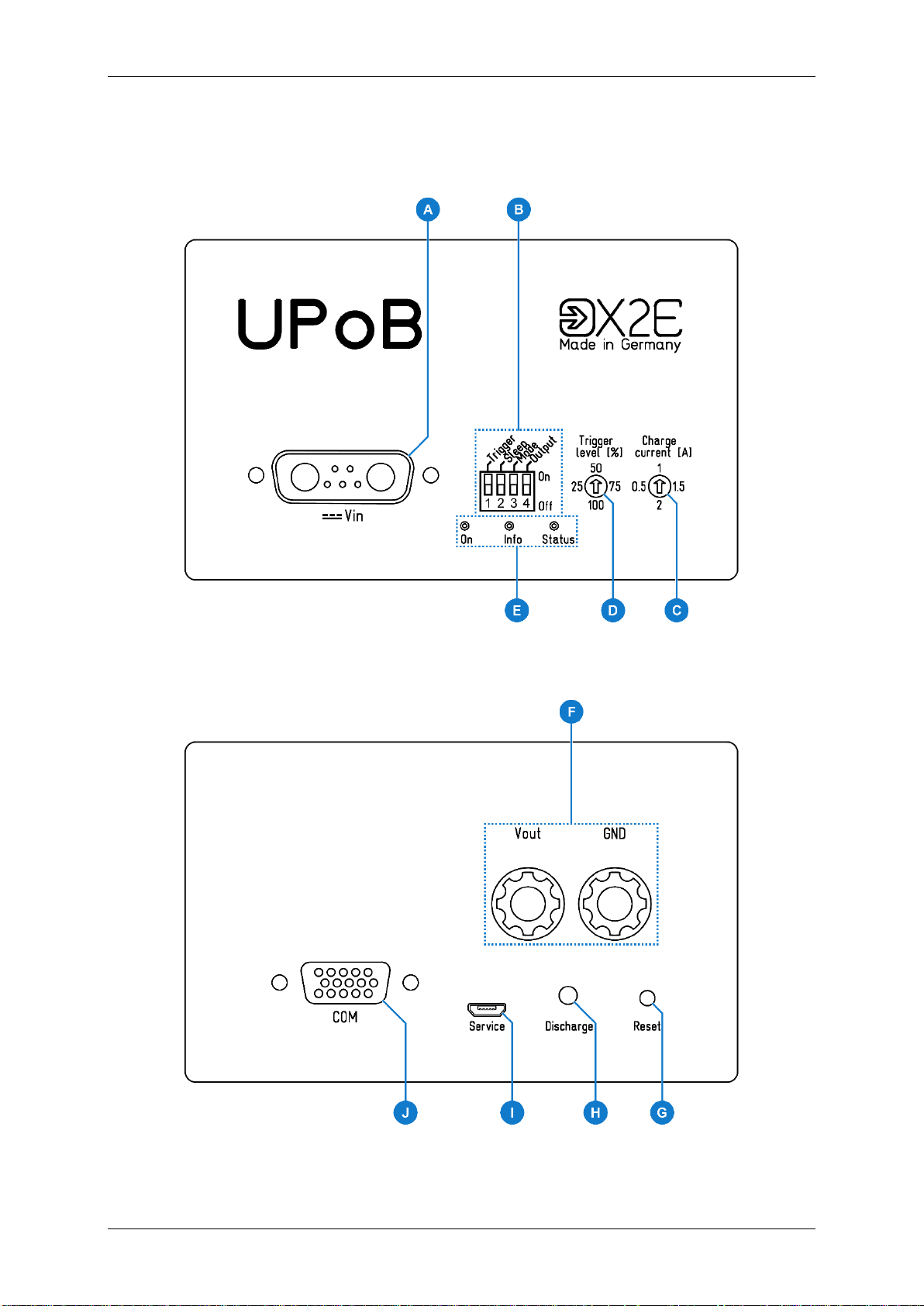
Front view
Back view
Connections and controls
8
Page 9

User Manual UPoB
Capacitors
Vin ≥ 10.3 V
Vin ≤ 10.0 V
Normal
mode
Bridge
mode
Vin (A)
Pin Function
A1 KL31
A2 KL30
Switching on/off threshold
Vin ≥ 10.9 V: UPoB switches on
≤ 10.0 V: UPoB switches off (if capacitors com-
V
in
pletely discharged)
Charging threshold
V
≥ 11.3 V: capacitors charging
in
≤ 11.0 V: capacitors stop charging
V
in
The capacitors get their maximum charging voltage
of 10.0 V if the input voltage is 12.0 V or h igher.
Mode-changing thresholds
V
≤ 10.0 V: UPoB switches into bridge mode
in
≥ 10.3 V: UPoB switches back into normal mode
V
in
(All values stated here apply to 0 A output load current. Please
refer to the appendix for thresholds of further currents.)
9
Page 10

User Manual UPoB
Impact of the output switch on other modes
Configuration (B)
Switch Function when On
Trigger (1)
sends trigger signal if the capacitance drops below the configured trigger level (D)
Sleep (2)
UPoB switches into sleep mode, where it does not send via
CAN and RS232, if:
the output load current drops below approx. 70 mA
UPoB wakes up if:
(Mode is On)
the output load current rises above approx. 80 mA
(Mode is Off)
the input voltage rises above 10.9 V
Mode (3)
mirrors the state of the input voltage at the output
deactivates the voltage output if:
the input voltage drops below 10.0 V
activates the voltage output if:
the input voltage rises above 10.9 V
Output (4) voltage output (F) activated
(All values stated here apply to 0 A output load current. Please refer to the appendix for thresholds of further currents.)
In order for the sleep and mode switches to work as described, the output
switch needs to be On. Otherwise, the UPoB cannot be woken up from
sleep mode if the mode switch is On, for example.
10
Page 11

User Manual UPoB
Charge current (C)
The charge current is included in the maximum input current of the UPoB.
Position Charge current
left 0.5 A
up 1 A
right 1.5 A
down 2 A
Trigger level (D)
If the trigger switch (1) is On and the remaining capacitance drops below the configured
level, the UPoB sends a trigger signal.
A trigger signal consists of:
an RS232 command to shut down a connected XORAYA data logger safely;
the data logger cannot be woken up by bus activity anymore
an impulse on the 5 V digital output for 100 ms
closing the relay output for 100 ms
illuminating the Info-LED for 100 ms
an acoustic signal
Position Trigger level
left charge at 25 %
up charge at 50 %
right charge at 75 %
down charge at 100 %
11
Page 12

User Manual UPoB
Overcurrent protection
LEDs (E)
LED Colour Meaning
yellow input voltage invalid or no input voltage
On
Info
Status
green input voltage valid
(off) no input voltage and capacitors discharged
yellow (blinking)
discharge button (H) pressed
green (1x blinking) trigger signal sent
yellow capacitors discharging,
charge higher than trigger level
yellow (blinking) capacitors discharging,
charge lower than trigger level
green capacitors completely charged
green (blinking) capacitors not charging and not discharging,
charge higher than 5 % and lower than 98 %
blue capacitors charging,
charge higher than trigger level
blue (blinking) capacitors charging,
charge lower than trigger level
(off) capacitors not charging and not discharging,
charge lower than 5 %
V
and GND (F)
out
(all)
red overcurrent
Bridge mode:
V
= 12 V
out
Normal mode:
V
V
≈ Vin - V
out
depends on the output load current (max. 500 mV at 5 A)
drop
drop
The UPoB is equipped with overcurrent protection that reacts within 500 ms
if the output load current rises above 5 A.
12
Page 13

User Manual UPoB
Pressing the reset button deactivates the voltage output for a short period of
Discharge restriction
Discharging at high ambient temperatures can destroy the UPoB.
Reset (G)
This button covers the following functions:
restart the UPoB
acknowledge overcurrent event and reactivate voltage output
if connected via service interface (I), switch the UPoB into bootloader mode to per-
form a firmware update (further information in the corresponding chapter)
CAUTION
Device damage due to sudden voltage drop
time. The connected system can be damaged or destroyed due to the sudden voltage drop.
Shut the connected system down safely before pressing the reset
button.
Discharge (H)
This button discharges the capacitors. The Status-LED indicates the current status of the discharging process.
The discharge button is deactivated in sleep mode and when input voltage
or output current is present. An already started discharge process stops
when input voltage or output current is registered.
CAUTION
Device damage due to overheating
Press the discharge button only at room temperature.
13
Page 14

User Manual UPoB
Service (I)
Use the Micro USB interface to update the firmware. For further information, refer to the corresponding chapter of this user manual.
The pin assignments conform to the USB standard.
COM (J)
The COM interface consists of:
an RS232 interface to communicate with a X
a CAN interface to send status messages
a 5 V digital output
a relay output with opener, closer and voltage input
Pin Function
2 COM_RS232_RXD
4 RELAIS_CLOSER
5 RELAIS_OPENER
6 STATUSCAN3_P
7 COM_RS232_TXD
9 5V_DIGITAL_IO
11 STATUSCAN3_N
13 RS232_GNDIN
15 RELAIS_VCCIN
ORAYA data logger
14
Page 15

User Manual UPoB
Overheating may result in malfunction or destruction of the UPoB.
Introducing the 4-mm plug s of the supplied power cable into low-voltage
A wrong power supply can result in damage or destruction of the UPoB.
Disconnect service interface during standard operating mode
Installation
Mounting
CAUTION
Device damage due to overheating
Do not operate the UPoB outside the specified temperature range.
Do not operate the UPoB in the vicinity of heat sources.
Ensure adequate air circulation.
Do not cover the UPoB with other objects.
Mount the UPoB in such a way that it does not pose a hazard at any time.
Connecting
DANGER
Electric shock due to improper connection
sockets can be fatal.
Never introduce the 4-mm plug into low-voltage sockets.
CAUTION
Device damage due to wrong power supply
Only connect the UPoB to power supplies that correspond to the
technical specifications.
Pay attention to the correct polarity when connecting.
Make sure that the service interface (I) is disconnected in standard operating mode. Pull the plug if necessary and connect it again before updating
the firmware.
15
Page 16

User Manual UPoB
Requirements for the DC power supply
COM interface
Connect the COM breakout cable to COM (J).
Connect the desired connectors of the COM breakout cable to the corresponding de-
vices.
Tighten all connector screws.
Voltage output
Connect V
and GND (F) to the connected system, such as a XORAYA data logger.
out
Voltage input
A 12 V DC power supply must provide a current of 6 A.
This applies to a char ge current of 0.5 A. For a higher charg e current, a
more powerful power supply is required.
Connect the power cable to V
(A).
in
Tighten the connector screws.
Connect the black connector of the power cable to 0 V or ground.
Connect the red connector of the power cable to a DC power supply in the specified
range.
Turn on the power supply.
The UPoB indicates its readiness by illuminating the On-LED.
16
Page 17

User Manual UPoB
Firmware update
Firmware updates provide bug fixes and new features for the UPoB. For this, you need a PC
which meets the following requirements.
Supported operating systems:
Microsoft® Windows® 7/8/10 (32 Bit or 64 Bit)
Hardware requirements:
Processor speed: at least 1 GHz
RAM: at least 1 GB
Execute the firmware update
Connect the UPoB to the power supply ( see c hapter Connecting).
Turn on the power supply.
Make sure the correct USB driver is installed.
Connect the UPoB via service interface (I) to your PC.
Press the reset button (G) on the UPoB.
Navigate to the folder where the firmware archive is located.
Unzip the archive.
Execute the file firmware_update_upob.bat.
Follow the instructions on the screen.
17
Page 18

User Manual UPoB
Entering liquids may result in malfunction or destruction of the UPoB.
Unauthorised opening may result in malfunction or destruction of the UPoB.
Within the European Union, the disposal of electrical devices is determined
Outside the European Union, please contact your local authority so as to
Cleaning
CAUTION
Device damage due to entering liquids
Disconnect the UPoB from the power supply before cleaning.
Make sure that no liquids enter the UPoB.
Clean the UPoB with a damp, soft cloth as needed.
Repair
CAUTION
Device damage from opening the device
Never open the UPoB.
Maintenance and repair must be carr ied out by X2E personnel only.
In case of malfunctions or damages, please contact X2E via e-mail to get information
about returning the UPoB: xoraya-return@x2e.de
Disposal
by national rules that are based on the directive 2012/19/EU of the European Parliament and of the Council on waste electrical and electronic equipment (WEEE). Accordingly, electrical and electronic equipment may not be
disposed of in household waste.
comply with the correct method of disposal for electrical devices.
18
Page 19

User Manual UPoB
Appendix
Technical specifications
General
Dimensions (H x W x D)
Input voltage
Output voltage
Output load current
Idle current
Quiescent current
DC voltage protection
Temperature range
RS232
Baud rate
Data bits
64.4 mm x 105 mm x 164 mm
max. 28 V
bridge mode: max. 10.0 V
normal mode: min. 10.3 V
bridge mode: max. 11.9 V
normal mode: max. Vin - 0.8 V
(at room temperature)
max. 4.8 A
max. 200 mA
max. 2 mA
max. 40 V
-40 °C to +85 °C
115,2 kbit/s
8
Parity bit
Stop bits
CAN
Baud rate
Termination
5 V digital output
Drive current
Relay output
Voltage input
Opener
Closer
no
1
500 kbit/s
120 Ω
max. 100 mA
5 V to 48 V
5 V to 48 V, 100 mA
5 V to 48 V, 100 mA
19
Page 20

User Manual UPoB
COM breakout cable
Pin Function
2 COM_RS232_RXD
4 RELAIS_CLOSER
5 RELAIS_OPENER
6 STATUS_CAN_ST_P
Pin Function
2 COM_RS232_RXD
3 COM_RS232_TXD
5 RS232_GNDIN
Pin Function
2 STATUS_CAN_ST_N
7 STATUS_CAN_ST_P
7 COM_RS232_TXD
9 5V_DIGITAL_IO
11 STATUS_CAN_ST_N
13 RS232_GNDIN
15 RELAIS_VCCIN
RS232
CAN
Pin Function
2 RS232_GNDIN
7 5V_DIGITAL_IO
Colour Function
red RELAIS_VCCIN
yellow RELAIS_OPENER
green RELAIS_CLOSER
5 V digital output (Digital_IO)
Relay output
20
Page 21

User Manual UPoB
Accuracy of values
Discharge times
The following values apply to a UPoB with 12.5 F capacitance and 12 V input voltage.
Because the stated times are determined empirically, the values might deviate under certain circumstances.
Output load Bridging time
XORAYA Minilogger V5 Advanced (≈ 0.7 A) 37 s
XORAYA V5+ C20 (≈ 0.9 A) 28 s
XORAYA Minilogger Z7 R8C4Ge2 (≈ 1 A) 26 s
XORAYA V5 C20L4B12FAS (≈ 1.6 A) 16 s
1 A 26 s
2 A 13 s
3 A 9 s
4 A 6 s
4.8 A 6 s
Trigger time
Output load
100 % 75 % 50 % 25 %
XORAYA Minilogger V5 Advanced (≈ 0.7 A) 1 s 9 s 18 s 27 s
XORAYA V5+ C20 (≈ 0.9 A) 1 s 7 s 14 s 21 s
XORAYA Minilogger Z7 R8C4Ge2 (≈ 1 A) 1 s 6 s 13 s 19 s
XORAYA V5 C20L4B12FAS (≈ 1.6 A) 1 s 4 s 8 s 12 s
1 A 1 s 6 s 13 s 19 s
2 A 1 s 3 s 6 s 9 s
3 A 1 s 2 s 4 s 6 s
4 A 1 s 1 s 3 s 4 s
4.8 A 1 s 1 s 3 s 4 s
21
Page 22

User Manual UPoB
Accuracy of values
in
out
in
out
Thresholds
The following graphs show the different thresholds, each dependent on the output load current I
Normal mode to bridge mode:
out
.
10.6
Because the stated voltages are determined empirically, the values might
deviate under certain circumstances.
10.4
10.2
10
V
9.8
9.6
9.4
0 0.5 1 1.5 2 2.5 3 3.5 4 4.5
Bridge mode to normal mode:
12.5
V
V
I
out
V
12
11.5
11
10.5
10
9.5
V
V
0 0.5 1 1.5 2 2.5 3 3.5 4 4.5
I
out
22
Page 23

User Manual UPoB
in
in
Switch-on threshold:
11.8
V
11.6
11.4
V
11.2
11
10.8
0 0.5 1 1.5 2 2.5 3 3.5 4 4.5
I
out
Charging threshold:
11.8
11.6
11.4
V
11.2
11
10.8
0 0.5 1 1.5 2 2.5 3 3.5 4 4.5
V
I
out
23
Page 24

User Manual UPoB
Status messages
The COM interface (J) sends the following CAN status messages cyclically.
CAN ID Content
0x120 internal states (for example DIP switch positions)
0x121 out put load current, output voltage, output power,
input voltage
0x122 capac it or voltage, capacitor current, capacitor power,
charge level
0x123 firmware version, hardware version, serial number
0x124 product ID, product variant, mount variant
24
Page 25

Page 26

Phone
+49 7275 9143 100
Fax
+49 7275 9143 109
E-Mail
info@x2e.de
Internet
http://www.x2e.de
X2E GmbH
Jahnstrasse 2b
76870 Kandel
GERMANY
 Loading...