

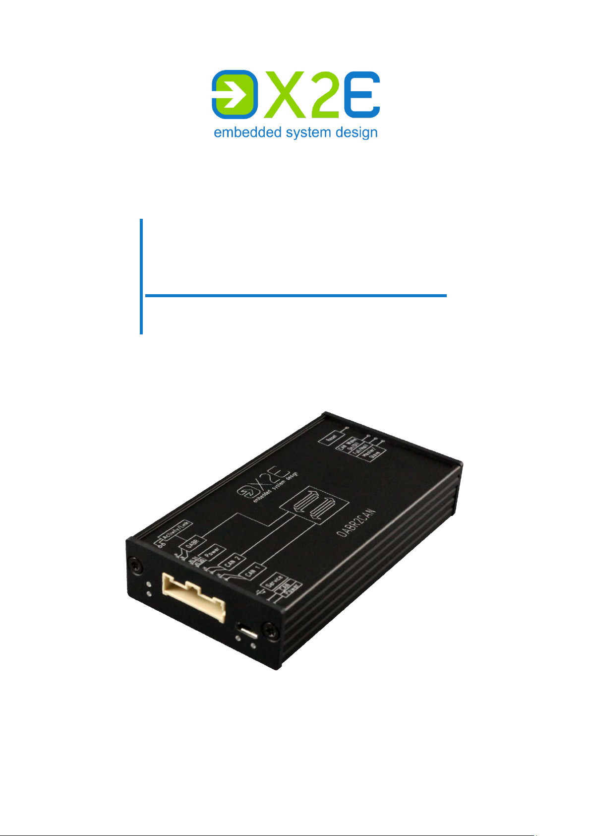
OABR2CAN
Media Gateway
User Manual
Version: 1.8 / November 2019

© 2019 X2E GmbH
This user manual is protected by copyright; all usual rights reserved. Reproduction of this user manual, even in
part, is only permitted with the approval of X2E GmbH. Any infringement will result in liability for damages and
may result in criminal prosecution.
All product names and brands used in this user manual are the property of their respective owners.

User Manual OABR2CAN
Table of contents
Introduction ............................................................................................. 4
Intended use ............................................................................................ 4
Delivery contents ..................................................................................... 4
General safety instructions ...................................................................... 5
Product overview..................................................................................... 6
Identification ............................................................................................. 6
Connections and controls ........................................................................ 6
Installation ............................................................................................... 9
Mounting .................................................................................................. 9
Connecting ............................................................................................... 9
Gateway configuration .......................................................................... 11
Install XORAYASuite ................................................................................ 12
Start Gateway configuration .................................................................. 13
Buttons ................................................................................................... 14
Gateway-Settings................................................................................... 15
Create and save configuration ............................................................... 15
Connect to gateway ............................................................................... 16
Transfer configuration ............................................................................ 17
Update firmware..................................................................................... 17
Disconnect gateway ............................................................................... 17
Cleaning ................................................................................................ 18
Repair ................................................................................................... 18
Disposal ................................................................................................ 18
Appendix ............................................................................................... 19
Technical specifications ......................................................................... 19
Message structure ................................................................................. 19
Pin assignments of the connection cable .............................................. 20
3

User Manual OABR2CAN
Introduction
Intended use
OABR2CAN is an automotive media gateway between one OPEN Alliance BroadR-Reach®
(OABR) interface and two high-speed CAN interfaces. A configurable routing table stores the
information of how the data is transferred between the interfaces.
You may only operate the gateway within the scope of the technical specifications provided
in this user manual. Additionally, the use in hazardous areas is not allowed.
The gateway meets the requirements of the EMC Directive of the European Union if the connecting cable supplied is used. The interface connection lines may be extended up to a maximum of 30 m, the voltage supply line, with sufficient cross section, up to 3 m.
You can find the declaration of conformity at the end of this user manual. Exact nam es of the
compliant product variants are available on request.
Delivery contents
OABR2CAN Media Gateway
connection cable (optional)
user manual
ORAYASuite
X
USB driver
Check to ensure that the delivery is complete and all hardware components are in sound
condition. If the delivery is incomplete or supplied components are damaged, contact X2E
immediately. Do not use damaged components.
4
User Manual OABR2CAN
Damages to the gateway or the connection cable can result in electric
Excessive vibrations, dirt or liquids may result in malfunction or destruction
Electronic components can be destroyed by electrostatic discharge.
General safety instructions
The OABR2CAN Media Gateway is only intended for use by qualified personnel. Read the
user manual and especially this chapter thoroughly before operating.
CAUTION
Electric shock due to damaged components
shock.
Check all components regularly for damages.
Only connect the gateway if all components are undamaged.
CAUTION
Device damage due to vibrations, dirt or liquids
of the gateway.
Avoid exposing the gateway to excessive vibrations, dirt or liquids.
Keep the gateway clean, especially plugs and sockets to ensure a
reliable contact.
Never open the gateway.
CAUTION
Device damage due to electrostatic discharge
Avoid touching connectors and connector pins.
Ground yourself before carrying the gateway in your hands.
Operate the gateway in an ESD-compliant environment.
5
User Manual OABR2CAN
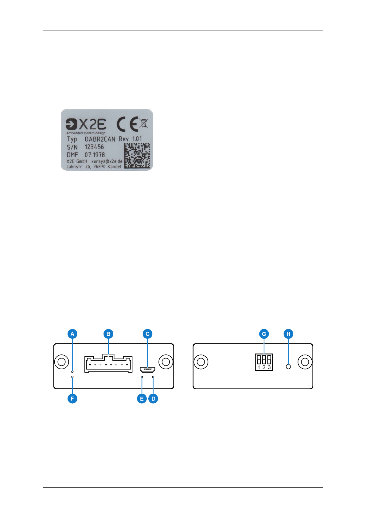
Front view
Back view
Product overview
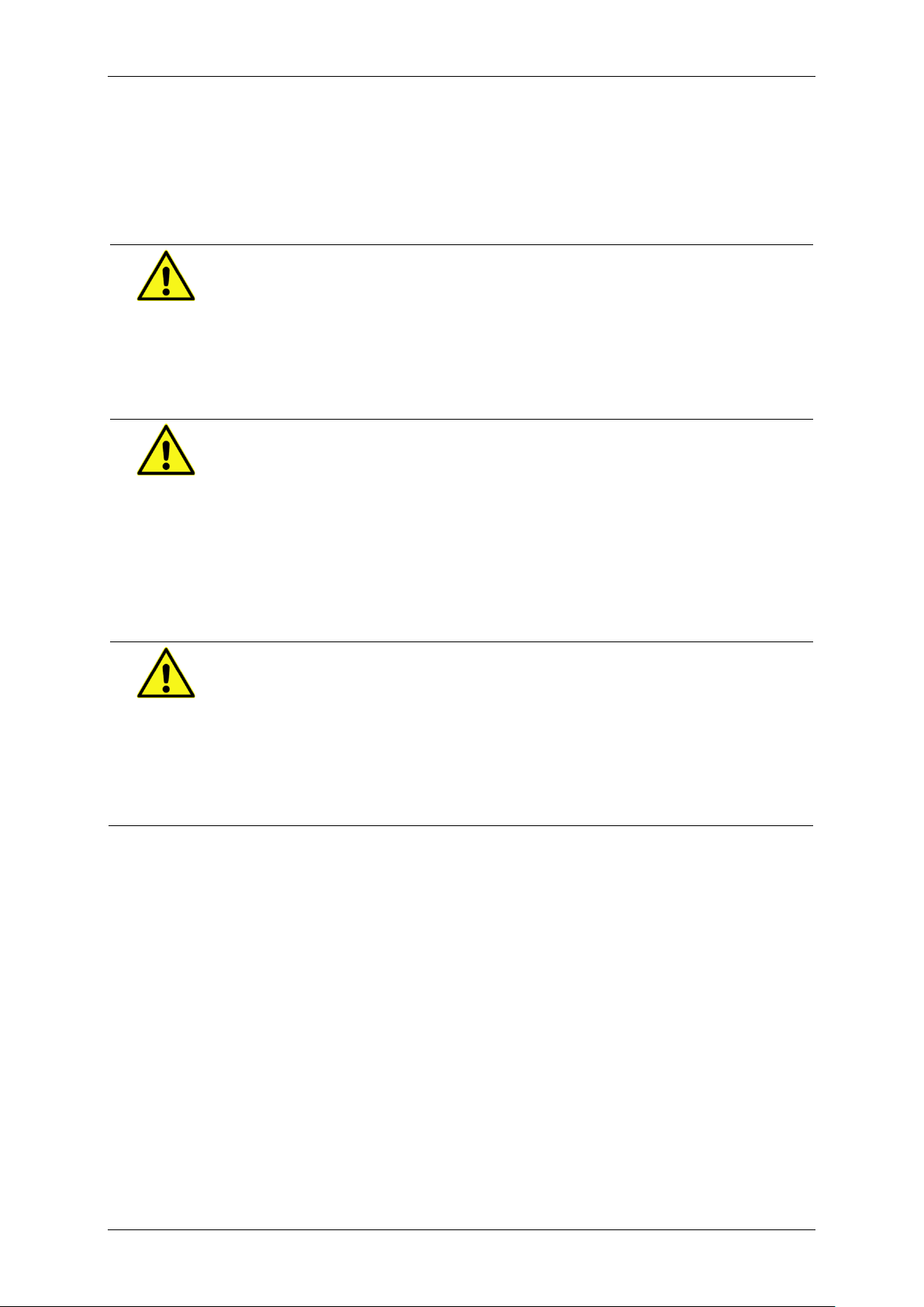
Identification
The identification plate is located on the bottom side of the OABR2CAN Media Gateway.
It contains information about:
Typ device type
Rev hardware revision
S/N serial number
DMF date of manufacture
This user manual applies to the OABR2CAN Media Gateway in hardware revision 1.01.
Connections and controls
The front side contains LEDs, the service interface and the combined connection for power,
OABR and CAN.
The control elements are located on the back side.
6
User Manual OABR2CAN
Activity LED for OABR (A)
Colour Meaning
green interface ready
green (blinking) data transmission on this interface
yellow USB bootloader mode
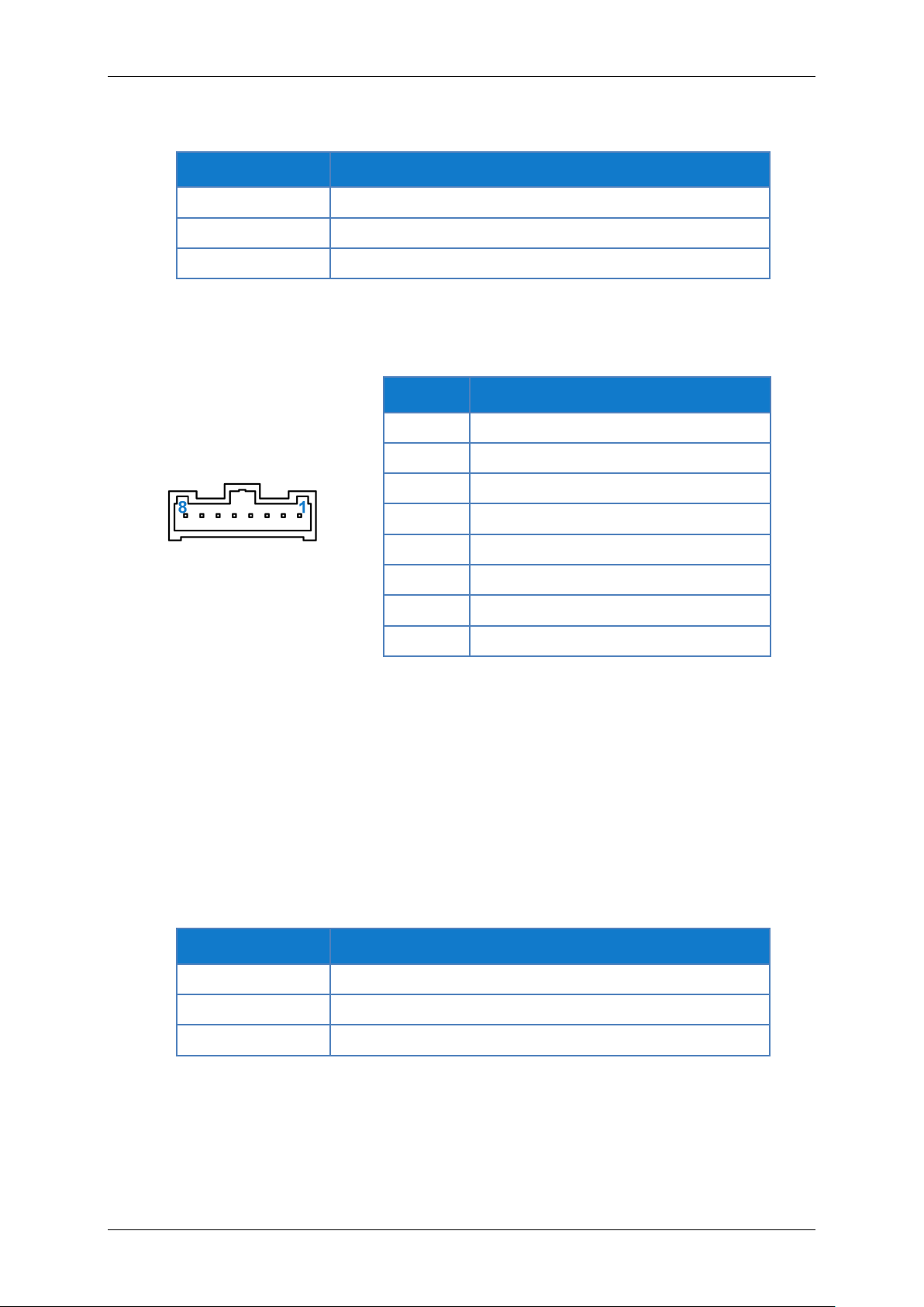
Connection for power, OABR and CAN (B)
Pin Function
1 CAN_1_H
2 CAN_1_L
3 CAN_2_H
4 CAN_2_L
5 KL30(Ubatt)
6 KL31(GND)
7 OABR_N
8 OABR_P
Service interface (C)
Use the Micro USB interface to change the configuration or to update the firmware. For further information, refer to the chapter Gateway configuration.
The pin assignments conform to the USB standard.
General status LED (D)
Colour Meaning
blue gateway in initialisation phase
green gateway ready
red error
7

User Manual OABR2CAN
LED for CAN (E)
Colour Meaning
blue at least one CAN interface in initialisation phase
green at least one CAN interface ready
red (blinking) data transmission on at least one CAN interface
Link LED for OABR (F)
Colour Meaning
red connection established
yellow USB bootloader mode
DIP switches (G)
No Function
1 switch the OABR interface between master (up) or
slave (down)
2 switch the OABR interface between full-out (up) and
half-out (down)
3 activate (up) or deactivate (down) sleep/wake mode via
CAN
Reset button (H)
This button is used to:
restart the gateway
switch the gateway into USB bootloader mode (further information in the chapter Con-
nect to gateway)
8

User Manual OABR2CAN
Overheating may result in malfunction or destruction of the gateway.
Introducing the 4-mm plug s of the supplied connection cable into low-volt-
A wrong power supply can result in damage or destruction of the gateway.
Disconnect service interface during standard operating mode
Installation
Mounting
CAUTION
Device damage due to overheating
Do not operate the gateway outside the specified temperature range.
Do not operate the gateway in the vicinity of heat sources.
Ensure adequate air circulation.
Do not cover the gateway with other objects.
Mount the gateway in such a way that it does not pose a hazard at any time.
Connecting
DANGER
Electric shock due to improper connection
age sockets c an be fatal.
Never introduce the 4-mm plug into low-voltage sockets.
CAUTION
Device damage due to wrong power supply
Only connect the gateway to power supplies that correspond to the
technical specifications.
Pay attention to the correct polarity when connecting.
Make sure that the service interface (C) is disconnected in standard operating mode. Pull the plug if necessary and connect it again before changing
the configuration or updating the firmware.
9

User Manual OABR2CAN
Requirements for the DC power supply
Energy management
The following instructions refer to the connection cable provided by X2E. If you use ot her cables, connect accordingly.
Plug the connection cable into the socket (B).
Connect the cable labelled OABR to an OABR device.
Connect one or both cables labelled CAN1 and CAN2 t o CAN busses.
The DC power supply must provide a continuous current of 120 mA. Use a
regulated power supply or the vehicle battery and pay attention to the required voltage and current levels.
Connect the black cable labelled KL31(GND) to 0 V or ground.
Connect the red cable labelled KL30(Ubatt) to a DC power supply in the specified
range.
Ensure that all connectors are firmly attached.
Turn on the power supply.
The gateway indicates its readiness by green illumination of the general status LED (D). As
soon as data is received at the OABR interface or the CAN interfaces, the data is converted
and sent according to the routing table configuration.
The OABR2CAN Media Gateway features an intelligent energy management that reduces the current consumption depending on the connected
CAN busses.
To activate the sleep/wake mode, DIP switch (G) No 3 needs to be ON
(= top position).
If there is no activity on the CAN busses within a configurable number of
seconds (see chapter Gateway-Settings), the gateway switches into sleep
mode. If there is activity again, it wakes up back to standard operating
mode.
10

User Manual OABR2CAN
Gateway configuration
With the tool Gateway configuration, part of X2E's XORAYASuite, you change the configura-
tion and update the firmware. The X
control X
ORAYA dataloggers and additional devices like the OABR2CAN Media Gateway.
ORAYASuite is a collection of programs to configure and
Supported operating systems:
Microsoft® Windows® 7 (32 Bit or 64 Bit)
Microsoft® Windows® 8 (32 Bit or 64 Bit)
Microsoft® Windows® 10 (32 Bit or 64 Bit)
Hardware requirements:
Processor speed: at least 1 GHz
RAM: at least 2 GB
Hard disk space: approx. 130 MB available
Software requirements:
Microsoft® .NET Framework Version 4.5 or higher
11

User Manual OABR2CAN
The OABR2CAN Media Gateway supports three modes depending on the routing direction:
OABR to CAN
CAN to OABR
CAN to CAN
These modes are set by configuring the receiving and sending interfaces in Gateway configuration. Can 1, Can 2, Ethernet 1 and Ethernet 2 are available.
Can 1 and Can 2 represent both physical CAN interfaces. Ethernet 1 and Ethernet 2 are logi-
cal partitions of the physical OABR interface. The partitioning is realised with UDP ports
(30501 and 30502 by default). For the routing from OABR to CAN or vice versa, each CAN
interface is assigned to a UDP port.
Example:
Can 1
Can 2
CAN messages are tunnelled as UDP packets through the SOME/IP protocol. For further information on SOME/IP, refer to the chapter Message structure.
Ethernet 1: UDP port 30501
Ethernet 2: UDP port 30502
Install XORAYASuite
Start the XORAYASuite installation wizard and follow the instructions.
Make sure that the component Gateway configuration is installed.
12

User Manual OABR2CAN
Start Gateway configuration
Start the XORAYASuite.
Click in the Windows notification area.
Select Extra tools > Gateway configuration.
13

User Manual OABR2CAN
Buttons
The following table displays a short overview of the toolbar buttons and the equivalent menu
commands. You find detailed step-by-step instructions on the subsequent pages.
Function Menu command
creates a new project Project
loads an existing project (*.xgc) Project
saves the current project to your PC:
as a project file (*.xgc)
as a configuration file compatible with the
gateway (*.cfg.hex)
as AUTOSAR XML files (*.arxml)
closes the current project Project
> New
> Load
Project
> Save
> Close
creates a new interface mapping
deletes the selected interface mapping
connects to the gateway or disconnects an established connection
loads a firmware file (*.hex) that overwrites the
firmware of the connected gateway
deletes the configuration in the process
loads a configuration file (*.cfg.hex) that overwrites
the configuration of the connected gateway
the firmware remains unchanged
saves the configuration file (*.cfg.hex) of the connected gateway to the PC
displays device information about the connected
gateway
jumps to the next occurrence of the search term
jumps to the previous occurrence of the search
term
-
Hardware
> Connect
Hardware
> Flash Firmware
Hardware
> Flash CFG
Hardware
> Get CFG
Hardware
> Info
-
-
sorts the message list alphabetically
sorts the message list by CAN-ID
14
-
-

User Manual OABR2CAN
Gateway-Settings
Gateway-Settings are general settings that apply to all interface mappings of the current project.
Setting Function
IP IPv4 address of the gateway
SubNet IPv4 subnet address of the gateway
Gateway IPv4 gateway address of the gateway
Multicast IPv4 address of the multicast group the gateway should
join
Variant f r eely selectable letter to label the current configuration
Sleep timeout number of seconds without CAN activity that puts the
gateway into sleep mode
requirement: DIP switch No 3 is ON (= top position)
Create and save configuration
Click to create a new project.
Configure the general Gateway-Settings (see chapter Gateway-Settings).
Click to create a new interface mapping.
Under Receive - RX, select the receiving Interface.
Load a DatabaseFile (DBC, AUTOSAR or FIBEX) that contains definitions of the
messages to r oute.
Depending on the selected receiving interface, specify the Baudrate or the Port.
Under Send - TX, select the sending Interface.
Depending on the selected sending interface, specify the Baudrate, the Port or op-
tionally a VLan ID.
Click OK.
The interface mapping is added to the table. In the lower-left part of the window, the messages from the DBC, AUTOSAR or FIBEX file are listed.
15

User Manual OABR2CAN
Target IP
Select a message and click to add this message to the routing table.
Repeat this step for up to 255 further messages if required.
or
Click somewhere in the message list, then
interface unfiltered.
or
Click somewhere in the message list, then
list (max. 256).
The number of routed messages is displayed in the table column Info.
If the sending interface is OABR, so Ethernet 1 or Ethernet 2, then specify
the Target IP that can also be a multicast address. This setting is saved for
every message individually.
Click to create further interfac e mappings if required.
Click to save the configuration.
Navigate to the target directory and specify a File na me.
Click Save.
and Yes to route all messages of the
and No to add all messages from the
Connect to gateway
Before you connect the gateway in the software, you must activate the USB bootloader
mode:
Make sure that the correct USB driver is installed.
Connect the gateway to the power supply (see chapter Connecting).
Turn on the power supply.
Connect the gateway via service interface (C) to your PC.
Press the reset button (H) with a pointed object.
The gateway indicates USB bootloader mode by yellow illumination of the LEDs (A) and (F).
Click to connect to the gateway.
An established connection is indicated by a blue border around the icon:
16

User Manual OABR2CAN
Firmware-Update deletes configuration
Disconnect properly
Transfer configuration
Establish a connection to the gateway (see chapter Connect to gateway).
Click to load a saved configuration.
Navigate to the directory that contains the configuration file and select the File name.
Click Open.
The gateway configuration is being overwritten.
Click
to verify that the Configuration Version and the Configuration Variant
are as expected.
Update firmware
Establish a connection to the gateway (see chapter Connect to gateway).
Click to load the firmware.
Navigate to the directory that contains the firmware file and select the File name.
Click Open.
The gateway firmware is being updated.
Click
to verify that the Firmware Version is as expected.
For that reason, you have to transfer a configuration again after the successful firmware update.
Disconnect gateway
Click .
Always click the disconnect button before you exit Gateway configuration or
pull the USB cable. Otherwise the gateway stays in USB bootloader mode
and is not routing messages.
17

User Manual OABR2CAN
Entering liquids may result in malfunction or destruction of the gateway.
Unauthorised opening may result in malfunction or destruction of the gate-
Within the European Union, the disposal of electrical devices is determined
Outside the European Union, please contact your local authority so as to
Cleaning
CAUTION
Device damage due to entering liquids
Disconnect the gateway from the power supply before cleaning.
Make sure that no liquids enter the gateway.
Clean the gateway with a damp, soft cloth as needed.
Repair
CAUTION
Device damage from opening the device
way.
Never open the gateway.
Maintenance and repair must be carried out by X2E personnel only.
In case of malfunctions or damages, please contact X2E via e-mail to get information
about returning the gateway: xoraya-return@x2e.de
Disposal
by national rules that are based on the directive 2012/19/EU of the European Parliament and of the Council on waste electrical and electronic equipment (WEEE). Accordingly, electrical and electronic equipment may not be
disposed of in household waste.
comply with the correct method of disposal for electrical devices.
18

User Manual OABR2CAN
Appendix
Technical specifications
Dimensions (H x W x D)
Supply voltage
Current consumption
Current consumption (standby)
CAN interface baud rate
CAN interface termination
Temperature range
21 mm x 56 mm x 104 mm
5 V to 28 V
max 120 mA (at 12 V)
max 4 mA (at 12 V)
100, 125, 250, 500 or 1000 kbit/s
120 Ω
-40 °C to +65 °C
Message structure
The OABR2CAN Media Gateway wraps up to three SOME/IP messages in one Ethernet
packet. For the tunnelling of CAN messages, the SOME/IP header is def ined as follows:
The complete identifier is encoded in the field CAN-ID in LSB-first order. The 29th Bit (labelled with e) is an indicator for an Extended Identifier.
Examples:
Standard Identifier 0x3E
Extended Identifier 0x6A
Length refers to the area starting at bit position 64. If the SOME/IP message transports a
CAN-Payload of 8 Bytes, Length is 16 Bytes and the whole message is 24 Bytes long.
The fields Client ID and Session ID have to be filled with 0x0 when tunnelling with
SOME/IP, as defined by the specification.
Protocol Version is the SOME/IP version, currently 0x1.
Interface Version is currently 0x0.
Message Type is NOTIFICATION, so 0x2.
Return Code is OK, so 0x0.
SOME/IP: 0x0000003E
SOME/IP: 0x2000006A
19

User Manual OABR2CAN
Pin assignments of the connection cable
Pin Function
1 CAN_1_H
2 CAN_1_L
3 CAN_2_H
Pin Function
2 CAN_1_L
7 CAN_1_H
Pin Function
2 CAN_2_L
7 CAN_2_H
4 CAN_2_L
5 KL30(Ubatt)
6 KL31(GND)
7 OABR_N
8 OABR_P
CAN1
CAN2
Pin Function
2 OABR_N
7 OABR_P
Colour Function
red KL30(Ubatt)
black KL31(GND)
OABR
Ubatt/GND
20


Phone
+49 7275 9143 100
Fax
+49 7275 9143 109
E-Mail
info@x2e.de
Internet
http://www.x2e.de
X2E GmbH
Jahnstrasse 2b
76870 Kandel
GERMANY
 Loading...