

Page 1
User Manual
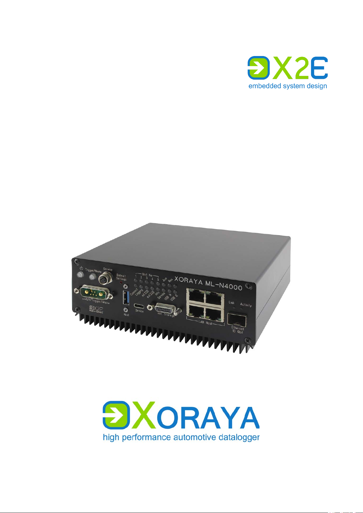
XORAYA ML-N4000
Edition: 1.0.2 / February 2020
Page 2

© 2020 X2E GmbH
This user manual is copyrighted; all customary rights reserved.
Reproduction of this manual, even in part, is only allowed with permission
of X2E GmbH. Offenders shall be liable to pay compensation and may be
subject to prosecution.
All product names and trademarks used in this manual are the property of
their respective owners.
X2E GmbH
Jahnstrasse 2b
76870 Kandel
GERMANY
Phone: +49 7275 9143 200
Telefax: +49 7275 9143 109
E-Mail: xoraya@x2e.de
Internet: http://www.x2e.de
Wiki: http://wiki.x2e.de
Page 3

USER MANUAL
TABLE OF CONTENTS
Table of contents
1 Introduction ................................................................................................................................ 5
1.1 About this user manual ............................................................................. 5
1.2 Validity of the user manual ....................................................................... 6
1.3 Representation conventions ...................................................................... 7
1.4 Pictograms ................................................................................................ 7
1.5 X2E-Wiki .................................................................................................... 9
2 Safety and warranty ............................................................................................................ 10
2.1 Intended use ........................................................................................... 10
2.2 Safety label on the device ........................................................................ 11
2.3 General safety instructions ...................................................................... 11
2.4 Product liability ....................................................................................... 14
2.5 Terms of use ........................................................................................... 14
2.6 Warranty ................................................................................................. 14
2.7 FCC notice .............................................................................................. 15
3 Product description ............................................................................................................. 16
3.1 Identification ........................................................................................... 17
3.2 Scope of delivery ..................................................................................... 18
3.3 Connections and controls ........................................................................ 19
4 Commissioning ...................................................................................................................... 27
4.1 Unpacking ............................................................................................... 27
4.2 Selecting an installation location ............................................................. 27
4.3 Installing the ML-N4000 .......................................................................... 27
4.4 Installing the X
ORAYASuite ....................................................................... 28
4.5 Connecting the ML-N4000 to the measuring environment ....................... 29
4.6 Connecting the ML-N4000 to the PC ........................................................ 32
4.7 Configuring terminators ......................................................................... 33
5 XORAYASuite .............................................................................................................................. 34
5.1 Starting ................................................................................................... 34
5.2 Menu bar
5.3 Status bar ............................................................................................... 38
5.4 Connecting and disconnecting the ML-N4000 .......................................... 39
5.5 Configuration .......................................................................................... 42
5.6 Resetting to factory defaults ................................................................. 112
5.7 Data recording ...................................................................................... 113
5.8 Hdd-Download ...................................................................................... 121
5.9 Viewer ................................................................................................... 127
5.10 Statistic ................................................................................................. 146
5.11 Convert ................................................................................................. 148
5.12 Firmware-Update ................................................................................... 151
5.13 TK Commandline .................................................................................. 153
5.14 Common elements ................................................................................ 155
................................................................................................ 35
6 Maintenance ......................................................................................................................... 169
6.1 Safety measures .................................................................................... 169
3
Page 4

USER MANUAL
TABLE OF CONTENTS
6.2 Cleaning ............................................................................................... 170
6.3 Repair ................................................................................................... 171
7 Storage, transport and disposal ............................................................................... 172
7.1 Storage ................................................................................................. 172
7.2 Transport .............................................................................................. 172
7.3 Disposal ................................................................................................ 172
8 Appendix................................................................................................................................. 173
8.1 Technical data ....................................................................................... 173
8.2 ML-N4000 pin assignments ................................................................... 174
8.3 Cable pin assignments .......................................................................... 177
8.4 Output formats ..................................................................................... 182
4
Page 5

USER MANUAL
1 Introduction
1.1 About this user manual
Read this user manual completely before using the XORAYA ML-N4000
for the first time.
Please consider this user manual as part of the product and make sure
it is easily accessible.
Provide this user manual upon transfer of the ML-N4000 to a third
party.
Request a replacement user manual upon loss.
This user manual contains important information for safe, proper and
efficient operation of the ML-N4000. Following this user manual strictly
helps in avoiding dangers, reduces repair costs and downtime, while
increasing the reliability and service life of the ML-N4000. It should be read,
understood and applied by those using the ML-N4000 according to the user
manual.
INTRODUCTION
Pay particular attention to:
the safety section ( Safety and warranty)
the text warnings of each section
Bear in mind that this user manual does not replace your responsibility as a
ML-N4000 user.
Subject to change without prior notice. This applies especially to changes
relating to technical enhancements.
5
Page 6

USER MANUAL
INTRODUCTION
1.2 Validity of the user manual
This user manual applies to X2E’s dataloggers of the XORAYA ML-N4000
series. The exact type specifications can be found on the nameplate.
( Identification)
The following instructions are key to operate the ML-N4000 and must be
strictly observed under all circumstances.
Information in this user manual is subject to change without prior notice
due to further technical developments and subsequent modifications. Please
ensure that you have the most current and complete user manual.
Functions described herein correspond to the ML-N4000 current delivery
state up to the development phase below:
Firmware version 4.0a.0015
X
ORAYASuite version 03.06.00.14
Please note that new features may not be described yet or may be described
incompletely.
Users can change certain properties and functions via the included software,
so that the ML-N4000 behaves differently than described herein. Users may
revert to factory defaults at any time by pressing the default button on the
front panel or via the supplied software. ( Resetting to factory defaults)
6
Page 7
USER MANUAL
Representation
Meaning
<Instruction>
User-executed action
<Instruction option 2>
Instruction options
<Outcome>
Outcome of an action or a series thereof
<Level 1a>
Maximum two-level enumeration
<Cross-reference>
Clickable cross-reference to a section or heading
arrow)
<Text>
Housing label, GUI element or other highlighting
#
Placeholder for numbers
(1) or (A)
Reference to numbered markers in graphics
1.3 Representation conventions
<Instruction option 1>
or
− <Level 2a>
− <Level 2b>
<Level 1b>
(In most Windows programs, you can return to
the previous position by pressing ALT + Left
INTRODUCTION
1.4 Pictograms
This manual uses pictograms to highlight and ensure faster recognition of
important or especially useful information.
Warning:
General information:
This type of symbols indicate warnings which must be
observed.
The following subsections contain a description of the
basic structure and relevance of different warning levels.
This symbol indicates general information.
General information includes application tips and
particularly useful information excluding warnings or
hazards.
7
Page 8
USER MANUAL
INTRODUCTION
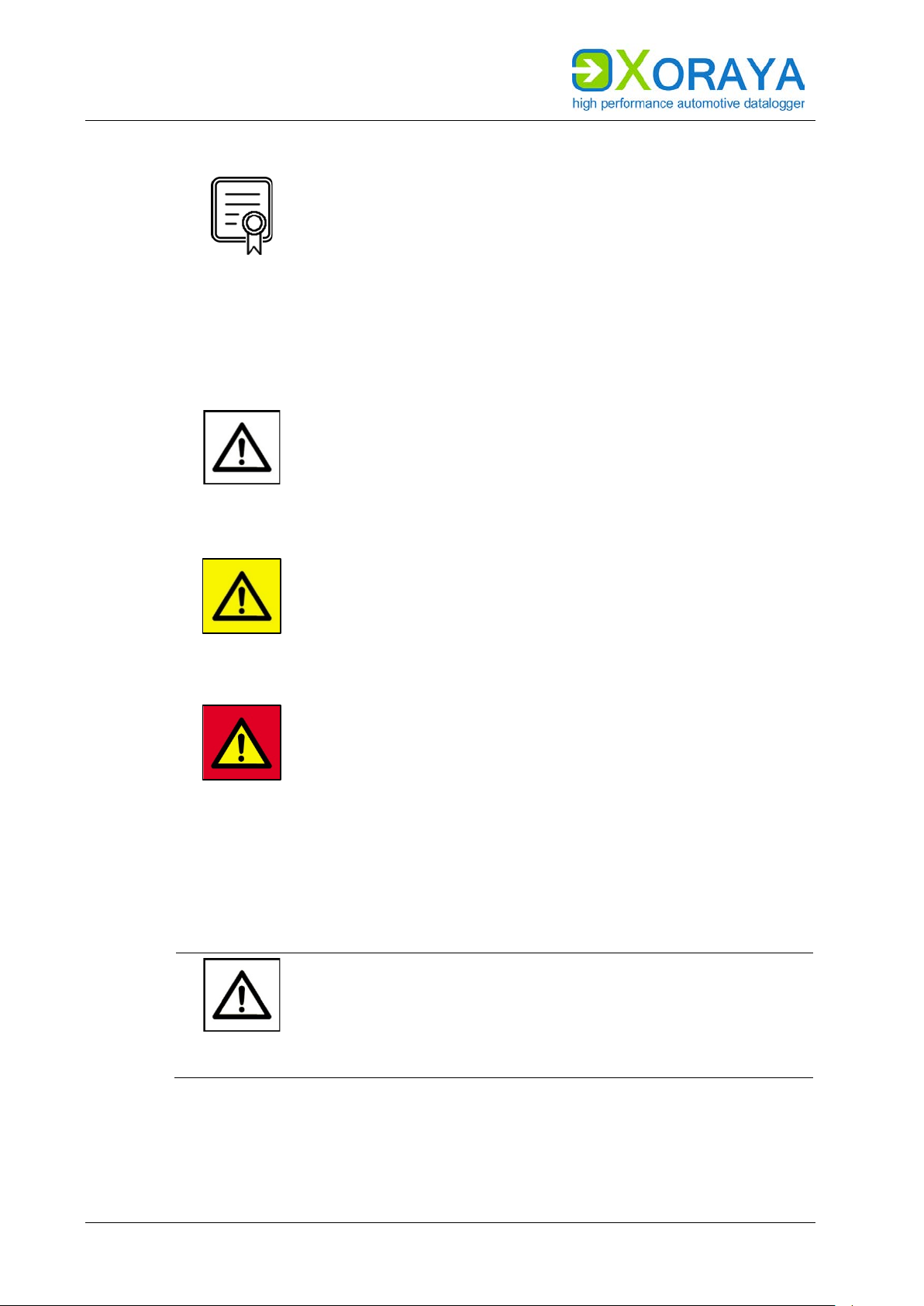
Licence information:
This symbol indicates licence information.
Licence information contains either general information
1.4.1 Meaning of warnings
Warnings are systematised according to the severity and probability of their
occurrence.
CAUTION
about licences for the ML-N4000 or indicates whether a
licence is required for a particular function.
This pictogram in conjunction with the word Caution
warns of a potentially dangerous situation, or an unsafe
procedure.
Ignoring this warning information could result in injury or
property and environmental damage.
This pictogram used in conjunction with the word
Warning warns of a potentially imminent danger to the
health and lives of people.
WARNING
Ignoring this warning could cause serious personal
injury, including death in the worst case.
This pictogram used in conjunction with the word Danger
warns of an imminent danger to the health and life of
people.
DANGER
Ignoring this warning causes serious personal injury,
including death in the worst case.
1.4.2 Structure of warnings
Warnings are separated from the surrounding text by lines set above and
below.
Danger types and sources
Explanation and consequence of danger
Actions to prevent danger
SIGNAL
WORD
8
Page 9

USER MANUAL
1.5 X2E-Wiki
The X2E-Wiki at http://wiki.x2e.de provides the following information:
Latest software
Latest firmware
Latest licence file
For access details, please send an email stating your contact data to
wiki@x2e.de. We will send you the appropriate access data. You may request
your access details at any time if necessary.
INTRODUCTION
9
Page 10

USER MANUAL
SAFETY AND WARRANTY
2 Safety and warranty
The XORAYA ML-N4000 dataloggers were developed according to the latest
state of the art and offer outstanding safety levels. During operation,
however, this safety level can only be achieved if the user complies with all
relevant safety regulations.
Upon measuring, safety regulations of the professional associations must be
observed.
Please contact an expert or the service of X2E GmbH when in doubt about
the operation, safety, or connection of the ML-N4000.
2.1 Intended use
The ML-N4000 is used for real-time acquisition of data communication in
automotive bus systems. You can perform, store and transfer measurements
to a PC, where you can read and analyse them using the GUI of the
ORAYASuite.
X
The ML-N4000 is intended for use only by trained personnel.
The ML-N4000 must not be used in residential or living areas. Its use is
strictly limited to industrial environments.
The ML-N4000 must not be used in hazardous areas.
Always operate the ML-N4000 within its technical specifications.
( Technical data)
The ML-N4000 may only be used under the conditions and for the
purposes for which it was designed.
Repairs may only be carried out by trained personnel of X2E GmbH.
Operational safety cannot be guaranteed after modifications or
conversions.
Except for data buses, never perform measurements on live parts.
The 4-mm plug of the power supply cable delivered must never be
introduced in low-voltage sockets.
The data lines may be extended up to a maximum of 30 m (USB: 3 m,
eSATA: 1 m) provided that they are shielded like the supplied cables.
The voltage supply may be extended up to a maximum of 3 m with
sufficient cross-section.
10
Page 11
USER MANUAL
2.2 Safety label on the device
You find the following safety label on the ML-N4000 top side:
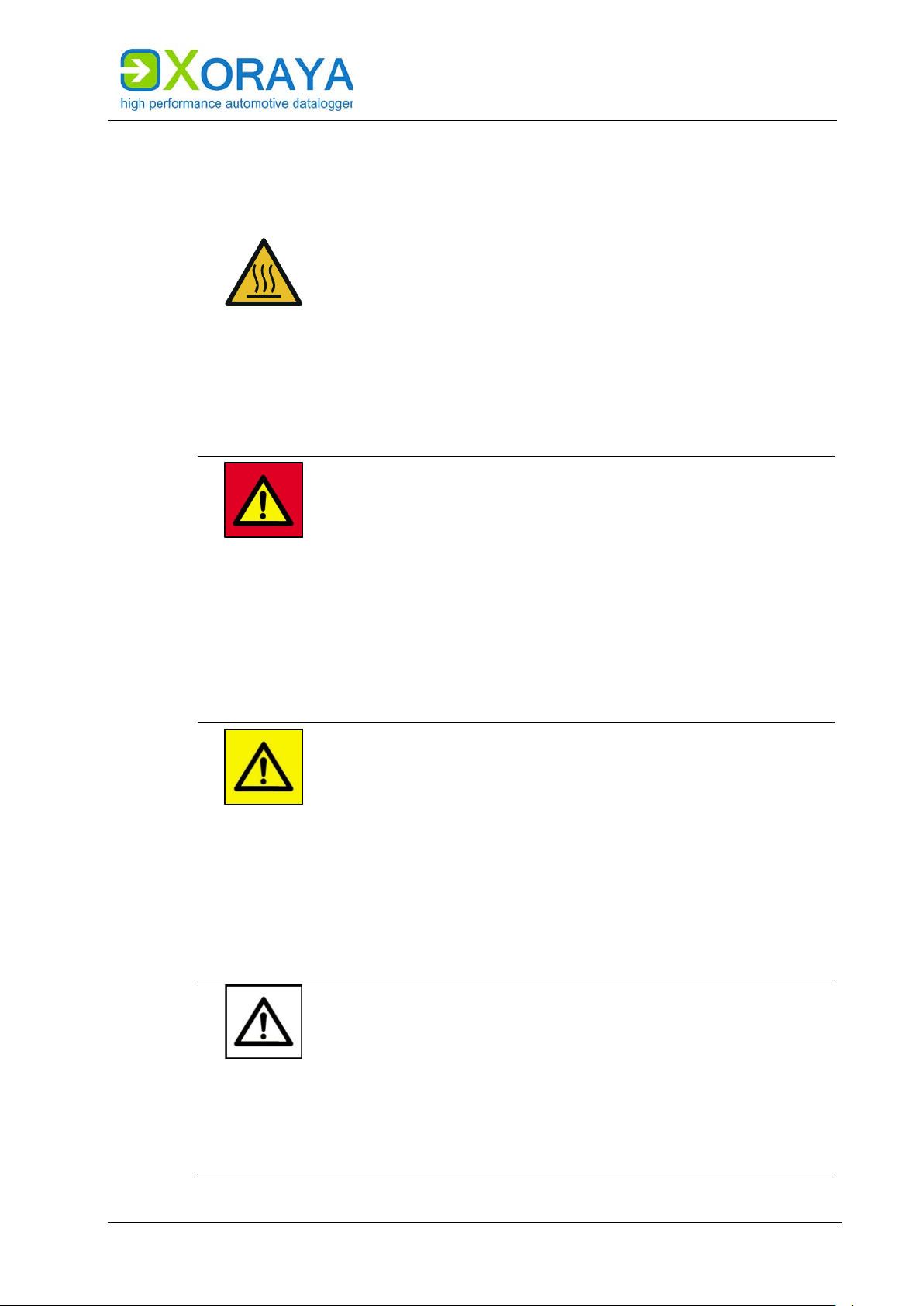
Burning hazard due to hot surfaces
Continuous operation can strongly heat up the ML-N4000.
As a result, it can burn the skin on the hands when
touching it.
Wear temperature-resistant ESD gloves when in
contact with the ML-N4000.
2.3 General safety instructions
Electric shock caused by damage to components
Any damage to the ML-N4000, power source or connection
cable may cause an electric shock.
DANGER
Switch on the ML-N4000 only if all components
appear undamaged.
SAFETY AND WARRANTY
WARNING
CAUTION
Only commission the ML-N4000 after a proper
installation or repair.
Check the connecting cable regularly for defects to
prevent damage to the power source.
Always install the ML-N4000 in de-energised status.
Defects influencing the environment
The incorrect ML-N4000 configuration can lead to the
temporary or permanent functional failure of connected
vehicles.
Connected vehicles being operated on public roads bear
an increased risk of injury and damage.
If available, use configuration templates provided by
the vehicle manufacturer.
Use preferably the passive recording modes of the
interfaces.
Device damage due to short circuit
Bent connector pins pose a short circuit risk. This can lead
to abnormal behaviour or destruction of the ML-N4000.
Likewise, devices connected to the measurement setup
may be also compromised.
Make sure that connector pins are not bent.
Check the ML-N4000 regularly for any deficiencies.
11
Page 12
USER MANUAL
SAFETY AND WARRANTY
CAUTION
CAUTION
Device damage due to electrostatic discharge
Electronic components can be destroyed by electrostatic
discharge.
Avoid touching connectors and connector pins.
Ground yourself before carrying the ML-N4000 in
your hands.
Operate the ML-N4000 in an ESD-compliant
environment.
Device damage due to overheating
Overheating can lead to abnormal behaviour or
destruction of the ML-N4000.
Do not operate the ML-N4000 outside the specified
temperature range.
Never operate the ML-N4000 near heat sources.
Please ensure adequate air circulation for operation.
CAUTION
CAUTION
CAUTION
Do not cover the ML-N4000 with other objects.
Device damage due to shocks
Excessive vibration can lead to abnormal behaviour or
destruction of the ML-N4000.
Avoid exposing the ML-N4000 to excessive vibration.
Device damage due to pollution
Avoid any contamination in plugs and sockets to ensure a
reliable contact.
Keep the ML-N4000 clean.
Device damage due to device opening
Unauthorised opening of the ML-N4000 can lead to
abnormal behaviour or destruction of the device.
Never open the ML-N4000.
Contact X2E GmbH should maintenance and repairs
be required.
12
Page 13
USER MANUAL
SAFETY AND WARRANTY
Device damage due to penetration of dust or liquids
Dust or moisture inside the ML-N4000 may cause
abnormal behaviour or destruction of the device.
CAUTION
Only operate the ML-N4000 with a closed housing.
Do not operate the ML-N4000 outdoors.
Do not operate the ML-N4000 outside the specified
temperature range.
Turn off the ML-N4000 and disconnect it from the
power supply before you start cleaning.
Damage due to improper device shutdown
Disconnecting the power supply during operation may
cause data loss and destruction of the ML-N4000.
CAUTION
Never disconnect the ML-N4000 from the power
supply while in operation.
Ensure proper connector seating and tighten the
screws if possible.
Only shut down the ML-N4000 through the
X
ORAYASuite or the power button on the front panel.
Pull the black plug connected to ground last when
disconnecting the ML-N4000 from the power supply.
Safety defects due to incorrect accessories and spare
parts
Accessories and spare parts that have not been
CAUTION
recommended by X2E GmbH negatively affect the safety,
functionality and precision of the ML-N4000.
X2E GmbH shall assume no responsibility whatsoever or
honour any warranty for damages arising from nonrecommended accessories and spare parts or incorrect
use.
Use only accessories recommended by X2E GmbH
and original spare parts.
13
Page 14

USER MANUAL
SAFETY AND WARRANTY
2.4 Product liability
In the following cases, the intended protection of the ML-N4000 may be
adversely affected. The liability is then transferred to the user.
The ML-N4000 is not used according to the manual.
The ML-N4000 is used outside the scope described in this manual.
The user modifies the ML-N4000 without proper authorisation.
2.5 Terms of use
If the installation of the ML-N4000 in a vehicle is intended for operation on
public roads, the user and the X2E GmbH must jointly perform a risk
analysis beforehand. This analysis must take into account the specific
installation requirements and the valid factory standards at the user's site.
Conditions set forth in framework contracts shall apply.
The ML-N4000 is continuously developed. The development process relies
on the cooperation between the user and X2E GmbH.
2.6 Warranty
The warranty period is 12 months. Device batteries, whether internal or
external, are excluded from the warranty. The warranty also excludes
damages arising from improper handling.
X2E GmbH guarantees that the media on which the software is located are
free of material errors under normal operating conditions. Users can return
any defective or materially erroneous media to X2E GmbH within a period of
30 days from date of original purchase. Media shall be replaced immediately
at no cost.
X2E GmbH guarantees that the software as described herein is basically
usable. X2E GmbH, however, shall assume no liability for the correctness
and the continued use of the software, given that the current state of the art
prevents the production of software suitable for all combinations of
hardware and software.
In particular, X2E GmbH cannot guarantee that the software meets any user
requirements, or that it is compatible with any programs the latter may have
selected. Responsibility for program selection and the consequences of
program use lie entirely with the user.
14
Page 15

USER MANUAL
X2E GmbH shall assume no liability for damages arising from faulty
recorded data, as well as damage due to incorrect configuration, data entry
and data transfer.
After configuring, we recommend to verify the proper operation and
plausibility of each sensor using some manual measurement over the entire
measuring range.
X2E GmbH shall assume no further liability. This limitation of liability also
applies to the personal liability of employees, representatives and organs of
X2E GmbH.
2.7 FCC notice
This equipment has been tested and found to comply with the limits for a
Class B digital device, pursuant to part 15 of the FCC Rules. These limits are
designed to provide reasonable protection against harmful interference in a
residential installation. This equipment generates, uses and can radiate
radio frequency energy and, if not installed and used in accordance with the
instructions, may cause harmful interference to radio communications.
However, there is no guarantee that interference will not occur in a
particular installation. If this equipment does cause harmful interference to
radio or television reception, which can be determined by turning the
equipment off and on, the user is encouraged to try to correct the
interference by one or more of the following measures:
SAFETY AND WARRANTY
Reorient or relocate the receiving antenna.
Increase the separation between the equipment and receiver.
Connect the equipment into an outlet on a circuit different from that to
which the receiver is connected.
Consult the dealer or an experienced radio/TV technician for help.
Changes or modifications made to this equipment not expressly approved
by may void the FCC authorization to operate this equipment.
15
Page 16

USER MANUAL
PRODUCT DESCRIPTION
3 Product description
The XORAYA dataloggers are processor-controlled storage units, designed to
record data from several and different data sources simultaneously. These
dataloggers are indeed unique in the automotive industry thanks to their
central 100-ns timestamp on all interfaces. Furthermore, its modular design
allows for a rapid and flexible adjustment to future demands. This is
stressed by the fact that all product phases, i.e. from design and
development to programming and production, are completed in-house.
The dataloggers can be equipped with many different interfaces:
Lowspeed-CAN, Highspeed-CAN and CAN-FD
FlexRay
LIN
RS-232
PSI5
Analog
BroadR-Reach
MOST25 and MOST150
Ethernet 100Base-T and 1000Base-T
GNLog and DLT via Ethernet and RS-232
CCP and XCP
GPS
The ML-N4000, based on the Xilinx Zynq® UltraScale+™ MPSoC, is the new
generation of the compact and inexpensive X
ORAYA datalogger. The built-in
supercapacitor unit is able to bridge power fluctuations and to shut the MLN4000 down safely in case of power failures.
Data can be directly saved to the storage medium (internally or externally)
or to a computer system via Ethernet interface. Both modes can also be
operated in parallel.
Operation can be managed via the graphical user interface X
ORAYASuite,
whereby the ML-N4000 can be configured, and data recorded and
downloaded from the ML-N4000. Moreover, you can evaluate the recorded
data and export them to many popular formats.
16
Page 17
USER MANUAL
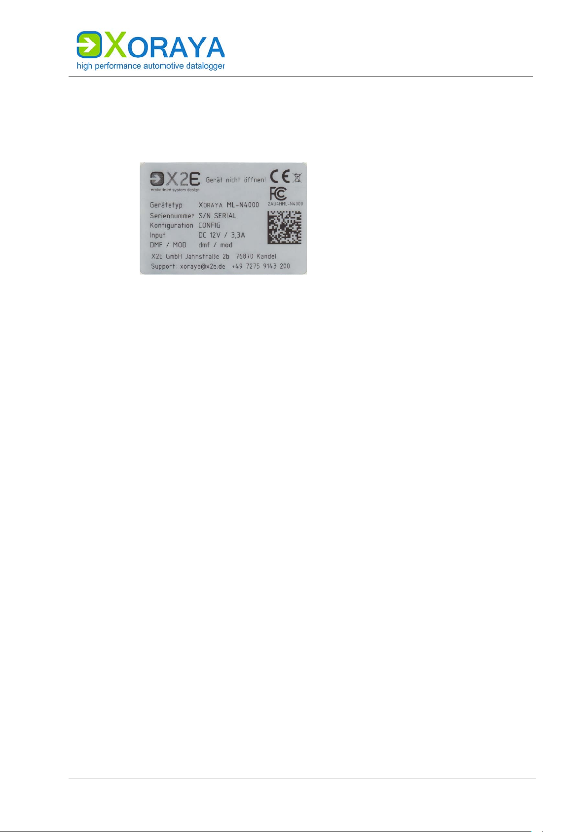
3.1 Identification
The top side of the ML-N4000 bears a silver nameplate, which contains the
following information:
Device type Product variant
Serial number Unique identification number for this ML-N4000
Configuration First block: Product ID
0200 X
PRODUCT DESCRIPTION
ORAYA Datalogger
Second block: Product variant
0600 X
ORAYA ML-N4000
Third block: Hardware revision
Input Maximum current consumption at given standard input
voltage
DMF / MOD Date of manufacture (DMF) and possibly of the last
modification (MOD)
Upon device-specific issues, always provide the serial number and
configuration.
The interface configuration of a ML-N4000 is variable and, therefore, not
recorded on the nameplate.
17
Page 18

USER MANUAL
PRODUCT DESCRIPTION
3.2 Scope of delivery
The following components are part of the delivery:
X
ORAYA ML-N4000
Power supply cable
Software
User manual
Cable set, depending on the interface configuration
The following accessories are optionally available:
Power supply cable with AC adapter (recommended)
X
ORAYA External Storage Unit
Additional cables
Mounting material
Device bag
Additionally, we recommend the following third-party accessories:
USB 3.1 standard cable, screwable, 1 m, from IDS (item number
AD00223)
SFP+ module FTLX8573D3BTL from Finisar
18
Page 19
USER MANUAL
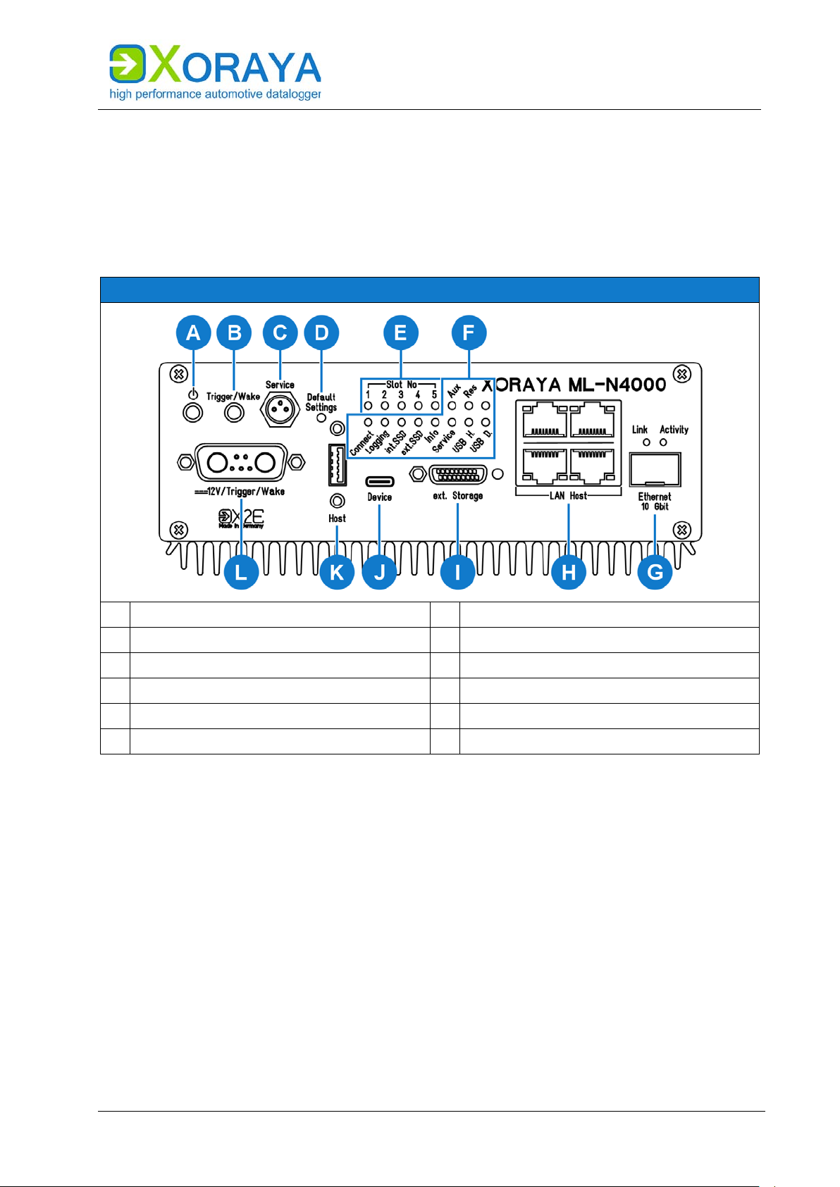
Front side
A
Power button
G
10 Gbit Ethernet interface
B
Trigger/wake button
H
LAN host interfaces
C
Service interface
I
ESU interface
D
Default button
J
USB host interface
E
Status LEDs of the log interfaces
K
USB device interface
F
General status LEDs
L
Power/trigger/wake port
3.3 Connections and controls
The front side of the ML-N4000 contains ports, buttons and LEDs for
operation and elementary functions.
The back side of the ML-N4000 contains, depending on the hardware
configuration, up to five log interfaces.
PRODUCT DESCRIPTION
Power button (A):
If you press this button while the ML-N4000 is operational, the device
switches to sleep mode.
If the ML-N4000 is operational and this button is pressed together with the
trigger/wake button (B), the ML-N4000 turns off completely.
You cannot turn off the ML-N4000 using this button when the device is
connected to a PC and the Connect LED is lit.
In this case, you can turn off the ML-N4000 via the Logger menu of the
ORAYASuite. Here, you may choose between two options, i.e. Shutdown and
X
Shutdown (no wake up). ( Logger)
19
Page 20
USER MANUAL
State of the ML-N4000
Function
Sleep mode
ML-N4000 wakes up
Switched on
Start HDD recording
Switched on, recording active
Short press: Setting a mark (an event) in
current recording
PRODUCT DESCRIPTION
Trigger/wake button (B):
The function of this button depends on the ML-N4000 state. The following
table describes these functions as delivered. Users can configure this
behaviour via the X
( Button)
Service interface (C):
In case of errors, this interface is used as a debugging interface by the X2E
support team.
ORAYASuite in the settings of the button interface.
the recording
Long press (3 seconds at least): Stop
Default button (D):
Press the default button with a pointed object for at least 3 seconds to reset
all ML-N4000 settings to factory defaults.
Status LEDs of the log interfaces (E):
A constantly lit status LED indicates an existing and activated log interface
on the corresponding slot. The LED flashes when messages are received.
20
Page 21
USER MANUAL
LED
Meaning
Connect
Connection between ML-N4000 and X
Suite is established
Logging
Logging in progress
may take longer depending on the queue fill level
int. SSD
Flashes when accessing the internal storage medium
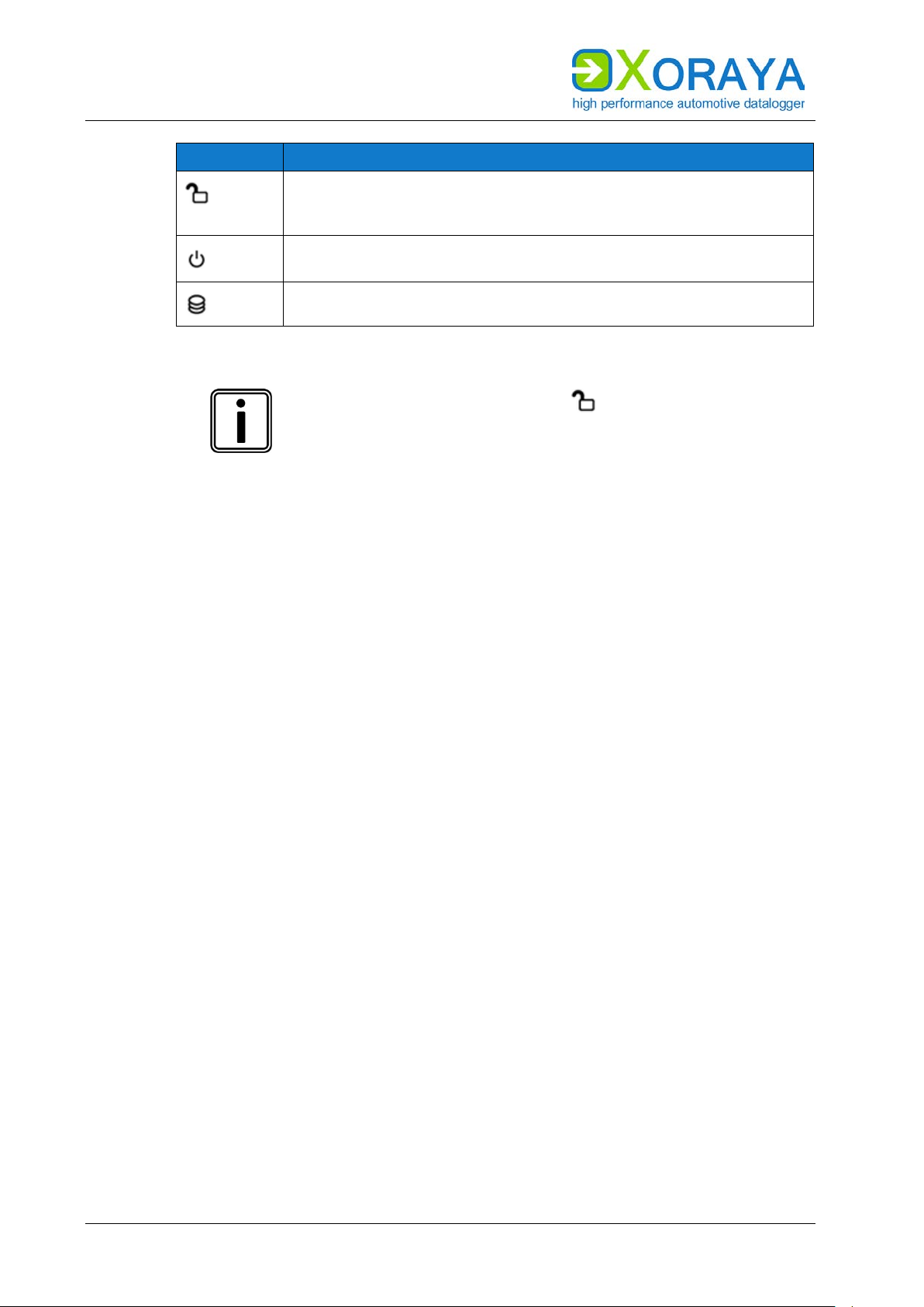
Green: connection disabled via button (unlocked)
Info
ML-N4000 is DHCP server
Service
Lights up constantly when the ML-N4000 is in firmware update or
Displays different error codes by flashing
USB H.
Flashes when accessing a connected USB flash drive
USB D.
(Currently not used)
Flashes when messages are received
Res
(Reserved)
PRODUCT DESCRIPTION
General status LEDs (F):
These LEDs indicate the operating status of the ML-N4000.
ORAYA
LED flashes as the logging stops, because the stopping process
ext. SSD Lights up when cable connection to XORAYA ESU is established
Red: connection enabled (locked)
recovery mode
Aux Lights up constantly when one of the additional interfaces without
hardware slot (for example GNLog, Button) is activated
10 Gbit Ethernet interface (G):
This interface can be used for data recording or as a faster alternative to the
1 Gbit host interfaces (H). A plugged-in SFP+ module is required. X2E
recommends the module FTLX8573D3BTL from Finisar.
LAN host interfaces (H):
The ML-N4000 features four ports to connect to a switch or directly to a PC.
This is necessary to control the ML-N4000 via software and exchange data.
ESU interface (I):
This port is used to connect the additional device X
ORAYA External Storage
Unit (ESU). If the ML-N4000 detects this device, the measurements in HDD
mode are saved there instead of to the internal storage medium.
( HDD mode)
The LEDs in the following table are both on the front and on the back side of
ORAYA ESU.
the X
21
Page 22
USER MANUAL
LED
Meaning
Green: connection disabled (unlocked)
Lights up green when X
ESU is voltage-supplied from the ML-
N4000
PRODUCT DESCRIPTION
Lights up when cable connection to ML-N4000 is established
Red: connection enabled (locked)
ORAYA
Flashes red when accessing the XORAYA ESU
Remove XORAYA ESU safely
To avoid data loss, always press this button for at least
one second before disconnecting the cable connection.
When the corresponding LED is lit green, you can pull the
cable.
USB device interface (J):
This port has currently no function for the user.
USB host interface (K):
By using a USB flash drive, the following functions are available:
Data recording
− Label the USB flash drive XORAYALOG and create the folder
usb_queue there.
− Check Record on USB stick in the Hard Disk category of the system
settings. ( Hard Disk)
− Start data recording in HDD mode. ( HDD mode)
Updating the firmware
− Create the folder xoraya_update on the USB flash drive and copy the
firmware archive there.
− Connect the drive and the firmware is automatically updated.
Generating the supportfile
− The supportfile is a set of files that you can send to X2E support to
help solve technical issues.
− Create the folder xoraya_supportfile on the USB flash drive.
− Connect the drive and the supportfile is automatically generated.
The Info LED flashes during the process.
Additionally, use the trigger input (L) or the trigger button (B) to safely
disconnect the USB flash drive after use. Check the corresponding action of
the Button interface. ( Button)
22
Page 23

USER MANUAL
PRODUCT DESCRIPTION
Power/trigger/wake port (L):
By default, the ML-N4000 must be supplied with 12 V DC voltage.
Optionally, it can also operate with power supplies in a certain specified
range. ( Technical data)
Trigger input and trigger button offer an analogous operation. A +12 V
signal level at the trigger input is equivalent to pressing the trigger button.
( Trigger/wake button)
The wake input allows waking up the ML-N4000 from sleep. To that end, the
wake signal must shift from 0 V to +12 V.
23
Page 24
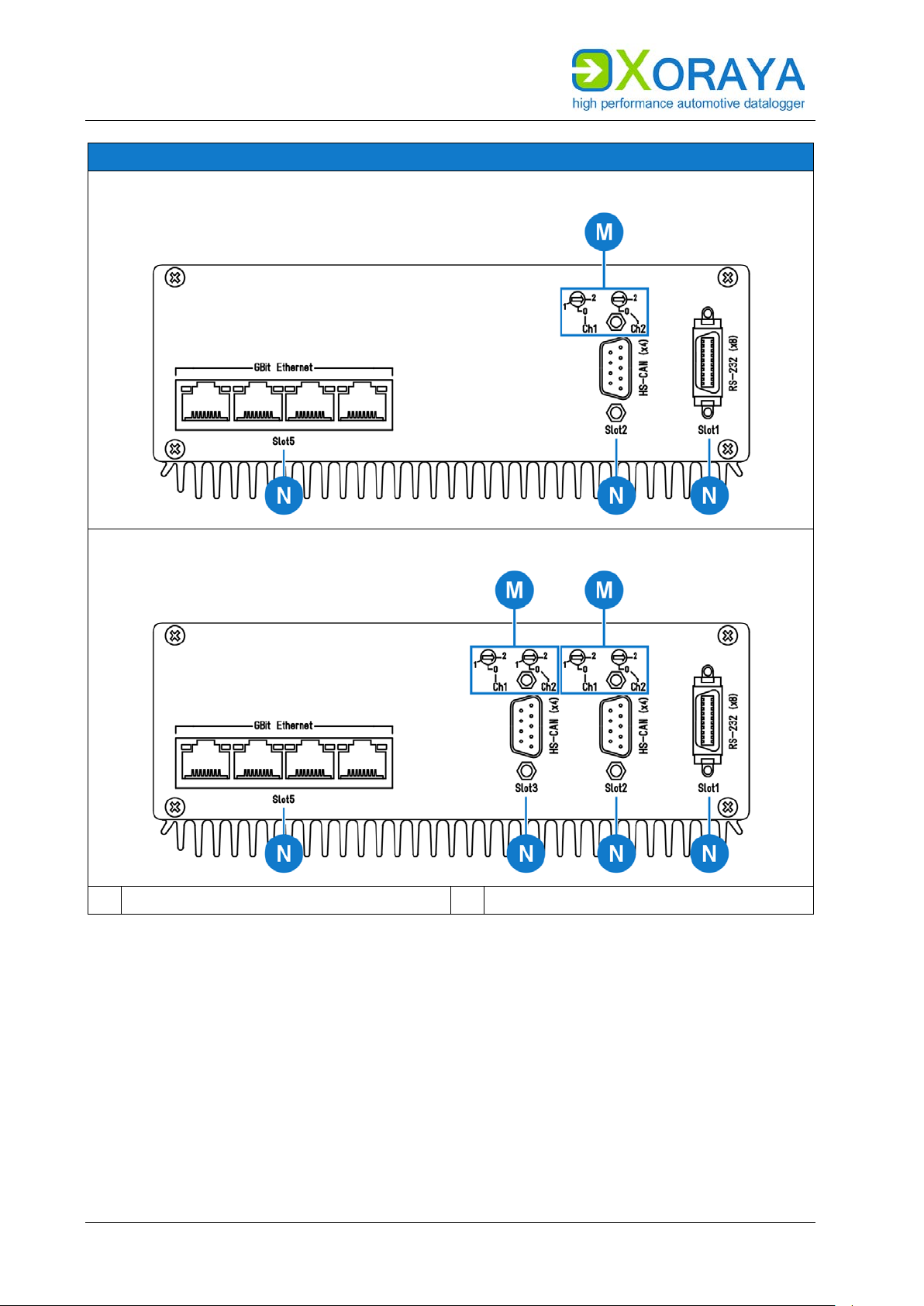
USER MANUAL
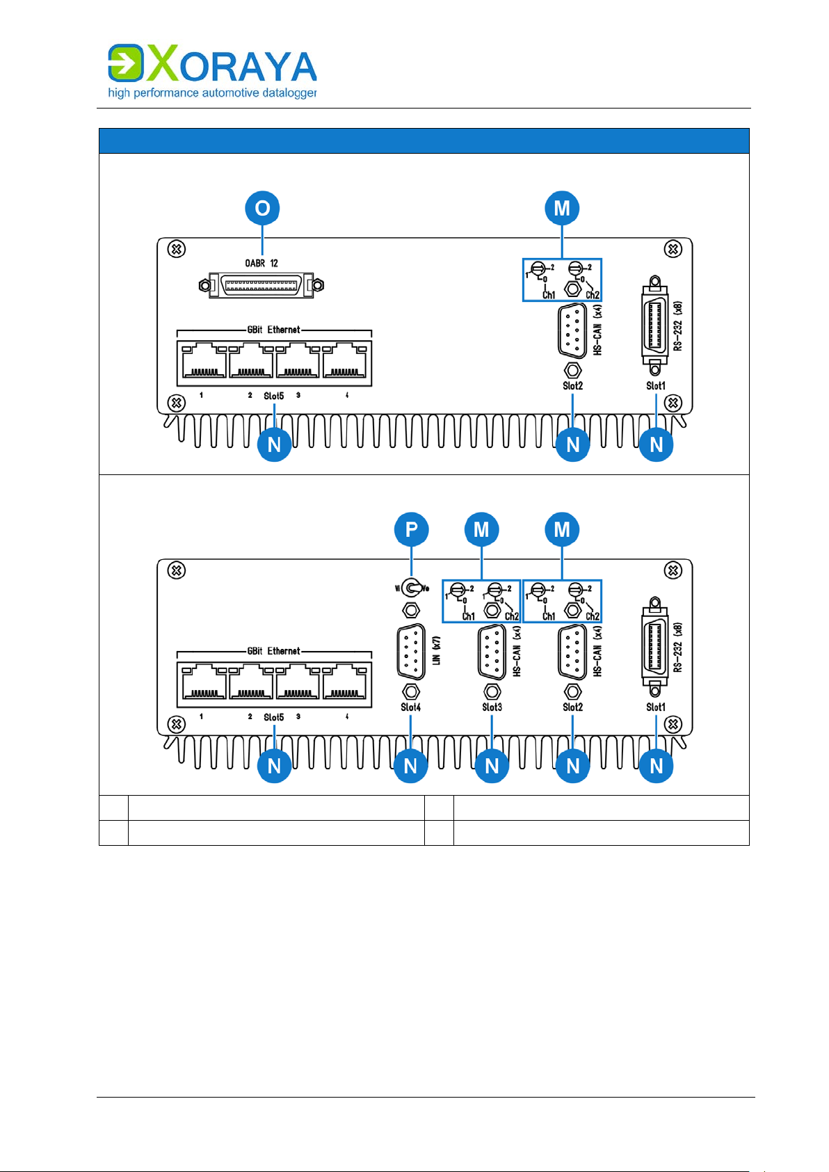
Back side (1)
8x RS-232, 4x CAN, 4x GBit Ethernet
8x RS-232, 8x CAN, 4x GBit Ethernet
M
Terminators
N
Log interfaces
PRODUCT DESCRIPTION
24
Page 25
USER MANUAL
Back side (2)
8x RS-232, 4x CAN, 4x GBit Ethernet, 12x BroadR-Reach/Base-T1
8x RS-232, 8x CAN, 7x LIN, 4x GBit Ethernet
M
Terminators
O
BroadR-Reach/Base-T1 interface
N
Log interfaces
P
LIN power supply internal/external
PRODUCT DESCRIPTION
Terminators (M):
Configure the built-in terminators for the CAN and FlexRay interfaces via
rotary switches on the back side of the ML-N4000.
( Configuring terminators)
25
Page 26

USER MANUAL
PRODUCT DESCRIPTION
Log interfaces (N):
The slots can be variably equipped with up to five interfaces.
Slot and channel number of each hardware interface are also displayed in
multiple locations of the X
( Interface configuration)
Main overview for all interfaces
Main overview for all channels of one interface type
Settings for the corresponding interface channel
Pin assignments can be found in the relevant section.
( ML-N4000 pin assignments)
BroadR-Reach/Base-T1 interface (O):
The housing label OABR stands for OPEN Alliance BroadR-Reach®.
ORAYASuite tool Configuration:
This interface is not part of the log interface slot system (N) but
implemented as an add-on board.
LIN power supply internal/external (P):
Use the internal power supply of the LIN measurement card only if the
connected LIN device uses the Minilogger Z7 voltage as a reference voltage.
Bear in mind that this is not possible when using the Minilogger Z7 in a 24-V
electrical system, for example. In this case, connect the external power
supply port to the corresponding reference voltage.
26
Page 27
USER MANUAL
4 Commissioning
4.1 Unpacking
Upon unpacking, check whether the delivery is complete and all components
appear in perfect condition. ( Scope of delivery)
Please contact X2E GmbH immediately should the delivery be
incomplete or upon damaged components.
Do not put any defective component into operation.
X2E GmbH can only accept your complaint and replace the affected
component upon prompt notification.
Keep original packaging
Keep the original packaging and packing materials for
later storage or further transport.
COMMISSIONING
4.2 Selecting an installation location
The ML-N4000 installation location must meet the following criteria:
Location of the DC power supply (12 V)
Distance of at least 2 cm to other devices
Solid and stable base
Adequate airflow
ML-N4000 front and back sides must not be covered
4.3 Installing the ML-N4000
X2E GmbH provides no special requirements for ML-N4000 installation.
Install the ML-N4000 in the vehicle so as to avoid a damage risk at any time.
27
Page 28
USER MANUAL
COMMISSIONING
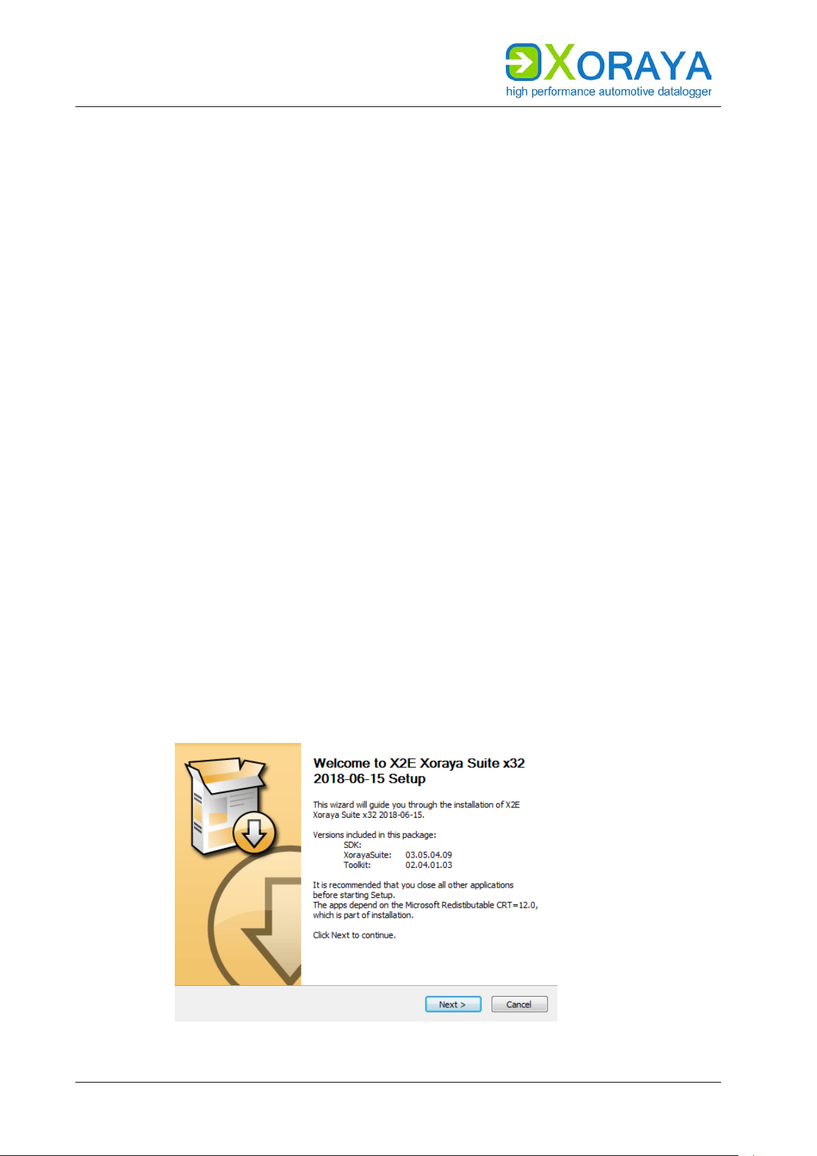
4.4 Installing the XORAYASuite
Users must install the GUI XORAYASuite on a PC with the following minimum
requirements to be able to configure the ML-N4000 and analyse the
recorded data.
Supported operating systems:
Microsoft® Windows® 7 (32 Bit or 64 Bit)
Microsoft® Windows® 8 (32 Bit or 64 Bit)
Microsoft® Windows® 10 (32 Bit or 64 Bit)
Hardware requirements:
Processor speed at least 1 GHz
RAM at least 2 GB
Storage space approx. 120 MB available
Software requirements:
Microsoft® .NET Framework Version 4.5 or higher
Installation:
Close all open programs.
Use the X
ORAYASuite setup wizard from the supplied data medium.
or
Download the latest version of the X
ORAYASuite from the X2E-Wiki.
( X2E-Wiki)
Start the setup wizard and follow the instructions.
28
Page 29
USER MANUAL
COMMISSIONING
4.5 Connecting the ML-N4000 to the measuring environment
This section describes how to connect the ML-N4000 to the measuring
environment.
Device damage due to incorrect connection sequence
The incorrect connection sequence can lead to abnormal
behaviour or destruction of the ML-N4000.
CAUTION
4.5.1 Interfaces
According to the numbering of the subsections,
connect the interfaces first and then the power
supply.
Please note the correct connection sequence from
top to bottom within the subsection.
Observe pin assignments
the ML-N4000 with the measuring environment. Wrong
pin assignments lead to measurement errors.
Please note the following sequence:
Connect the data cables of all data buses to be monitored in the
measuring environment.
Connect the data cables to the appropriate ML-N4000 ports.
Wherever possible, tighten the connector screws on the ML-N4000 and
in the measuring environment.
The ML-N4000 is connected to all data buses to be monitored.
Loss of data due to port disconnections
Please note the port pin assignments when connecting
To avoid data loss, never disconnect the ML-N4000
during the current recording from connected data buses.
Furthermore, make sure that all connectors are firmly
attached and the screws are tightened.
29
Page 30
USER MANUAL
COMMISSIONING
4.5.2 Power supply
This chapter describes the default connection to a DC power supply via the
supplied power cable. If you use the optionally available power cable with
AC adapter, please note the specifications on the adapter label.
DANGER
CAUTION
Electric shock due to improper connection of the power
supply
Introducing the 4-mm plugs of the supplied power cable
into low-voltage sockets can be fatal.
Never introduce the 4-mm plugs into low-voltage
sockets.
Connect the supplied power cable only to a power
source that meets the prescribed technical
conditions.
Damage due to incorrect power supply
Using an incorrect power supply can lead to abnormal
behaviour or destruction of the ML-N4000.
Use only the supplied power cable.
Please ensure correct polarity upon connection.
Make sure that the power supply used meets the
prescribed technical conditions.
Make sure that the power supply lies within
permissible operating voltage of the ML-N4000.
Please note the allowable voltage level when feeding
external signals.
Please note the technical specifications on the label
when using the optionally available power cable with
AC adapter.
Damage due to faulty connection
When connecting with live contacts, transient fault
currents with entrained mass may arise on interface
CAUTION
connections which have been already connected.
Please ensure contacts are de-energised when
connecting the ML-N4000 to the power supply.
30
Page 31

USER MANUAL
COMMISSIONING
Continuous current of the DC power supply
A 12 V DC power supply must deliver a continuous
current of 1 A with 3.3 A peaks. Use a regulated power
supply or a car battery and note the required voltage and
current levels.
Please note the following sequence:
Connect the power cable to port (L) on the ML-N4000.
( Connections and controls)
Tighten the connector screws.
Connect the black plug of the cable to 0 V or ground.
Connect the red plug to the power supply.
The ML-N4000 is securely connected to the measuring environment.
Once the supply voltage is established, the ML-N4000 turns on and displays
its operational status via the power button LED (A).
Damage due to improper device shutdown
Disconnecting the power supply during operation may
cause data loss and the destruction of the ML-N4000.
CAUTION
Never disconnect the ML-N4000 from the power
supply while in operation.
Ensure proper connector seating and tighten the
screws if possible.
Only shut down the ML-N4000 through the
X
ORAYASuite or the power button on the front panel.
Pull the black plug connected to ground last when
disconnecting the ML-N4000 from the power supply.
31
Page 32

USER MANUAL
COMMISSIONING
The ML-N4000 is equipped with an intelligent energy management system
that lowers power consumption to about 1 mA (at 12 V supply voltage) in
sleep mode.
The device goes into sleep mode via the following actions or under the
following conditions:
Pressing and holding the power button (A) for at least 2 seconds.
If no data reach the log interfaces and no connection to the
Users can wake up the ML-N4000 from sleep mode as follows:
Pressing the power button (A)
Switching the power supply off and on
Signal change from 0 V to +12 V at the trigger or wake input (L)
Current recording stops automatically.
X
ORAYASuite is established for 10 minutes, the ML-N4000 shuts down
automatically. This behaviour is configured using the main setting
Automatically Switch Off. ( Main Settings)
Pressing the trigger/wake button (B)
Activity on a wakeable log interface
4.6 Connecting the ML-N4000 to the PC
This section describes how to connect the ML-N4000 to the PC. To do so,
you will need a standard network cable.
Proceed as follows to connect:
Connect the network cable to a switch.
or
Connect the network cable directly to your PC.
Connect the network cable to one of the LAN host interfaces (H) or the
10 Gbit Ethernet interface (G). ( Connections and controls)
The ML-N4000 is fully connected.
32
Page 33

USER MANUAL
Position
Resistance
0
Open (∞)
1
2.6 kΩ
2
120 Ω
Position
Power supply
Vi
Internal
Ve
External
4.7 Configuring terminators
Configure the built-in terminators via the rotary switches (M) on the
back of the ML-N4000. ( Connections and controls)
For the LIN interface, select between internal or external power supply
via the toggle switch (P)
4.7.1 4x CAN
The channels 3 and 4 have the value Open and, therefore, are not
terminated.
COMMISSIONING
4.7.2 7x LIN
Use the internal power supply of the LIN measurement card only if the
connected LIN device uses the Minilogger Z7 voltage as a reference voltage.
Bear in mind that this is not possible when using the Minilogger Z7 in a 24-V
electrical system, for example. In this case, connect the external power
supply port to the corresponding reference voltage.
33
Page 34

USER MANUAL
Tool
Function
Configuration
Customise the ML-N4000
behaviour
Online-Logging
Start and stop logging
Hdd-Download
Download measurements from
the ML-N4000 storage medium
Viewer
Evaluate measurements
Statistic
Evaluate bus statistics
Convert
Convert log data to other formats
Firmware-Update
Update firmware
X
Toolkit
XORAYASUITE
5 XORAYASuite
This chapter describes the operation of the graphical user interface
ORAYASuite.
X
5.1 Starting
Perform all commissioning steps. ( Commissioning)
Start the X
or
Start the X
ORAYASuite by double-clicking the desktop icon.
ORAYASuite from the Windows Start menu.
Upon start, XORAYASuite provides access to the
various tools.
TK Commandline Command line access to the
ORAYA
The XORAYASuite is started.
Windows notification area
continues to operate in the background. Click the icon in
the Windows notification area to access tools or to close
ORAYASuite.
the X
Even after closing the launcher, the X
ORAYASuite
34
Page 35

USER MANUAL
Command
Description
Open configuration
Opens a configuration file (XML)
Save configuration
Saves the current configuration
Save configuration as
Saves the current configuration under a different
name
Save interface configuration
Saves the current interface configuration under a
everything except the interface configuration
Open
Opens an info file (DLI) and the associated log data
log data
Close
Closes the open log data
Open SWU/XSWU file
Opens a firmware image
interface from the ML-N4000
and opens them when needed
Export preferences
Exports the output format settings in a preference
file (XML)
Import preferences
Imports the output format settings from a
preference file (XML)
Exit
Closes the tool
5.2 Menu bar
This section describes the five main menus of the menu bar.
Individual menu commands are not available in every tool.
5.2.1 File
Among other things, you can use the File menu to open and save files, or
close the tool.
XORAYASUITE
as
different name
The subitem System settings and signals saves
Alternatively: ZIP archive containing info file and
Refresh properties Reloads the current configuration of a selected
Recent files Displays the most recently opened info files (DLI)
35
Page 36

USER MANUAL
Command
Description
Connect
Connects the selected ML-N4000
Disconnect
Disconnects the active connection to the ML-
Offline-Logging > Start
Starts the logging process on the ML-N4000
storage medium
storage medium
Online-Logging > Start
Starts the logging process on the PC
Online-Logging > Stop
Stops the logging process on the PC
µT-Z7/Probe)
Probe-Logging > Stop
Stops probe logging
Save changed configuration
permanently
Stores the changed settings permanently on the
ML-N4000
configuration > Create
(profile active) in the customer-default profile
configuration > Load
into the active profile
Reset configuration to factory
settings > Interfaces
Resets the ML-N4000 interface configuration to
factory defaults
Reset configuration to factory
settings > System
Resets the ML-N4000 system configuration to
factory defaults
Format HDD
Formats the ML-N4000 storage medium
Local
current system time of the PC
Vehicle
current system time of the connected vehicle
Restart
Restarts the ML-N4000
Restart and reconnect
Restarts the ML-N4000 and reconnects
Shutdown
Puts the ML-N4000 in sleep mode
Shutdown (no wake up)
Shuts down the ML-N4000 completely
XORAYASUITE
5.2.2 Logger
Among other things, you can use the Logger menu to connect or disconnect
the ML-N4000 with the X
Offline-Logging > Stop Stops the logging process on the ML-N4000
Probe-Logging > Start Starts probe logging
ORAYASuite.
N4000
(further information in the quick manual X
ORAYA
Customer default
Customer default
Synchronize time with >
Synchronize time with >
Stores the current permanent configuration
Loads the customer-default configuration profile
Sets the system time of the ML-N4000 to the
Sets the system time of the ML-N4000 to the
This menu does not appear in the Viewer and Convert tools.
36
Page 37

USER MANUAL
Command/Setting
Description
Normal
Normal view
Detail
Detail view that displays all categories and properties
Tab selection
Determines which tabs are shown in the
Online-Logging tool
measurements
Autosize columns
Adjusts the width of the columns in the Hdd-Download
tool to ensure all are visible simultaneously.
22 Type spread
Hdd-Download tool
Command
Description
Logger manual
Opens the ML-N4000 user manual
About
Displays system information on the software and, if
connected, on the ML-N4000
Update software
Opens the X2E-Wiki to download the current
XORAYASuite version
Show logfile
Displays a log file for the tool
Supportfile
Generates a set of files that you can send to X2E
support to help solve technical issues
5.2.3 View
Among other things, you can use the View menu to switch between normal
and detail view.
Tile windows vertically/
horizontally
1 Comment
…
in the Configuration and Online-Logging tools
Determines whether the elements Export settings and
Output formats selection in the Hdd-Download tool are
displayed next to or below the list of sessions or
Determines which tabs are shown in the
Hdd-Download tool
XORAYASUITE
Legend Determines whether the legend is shown in the
This menu does not appear in the tools Viewer, Convert and
Firmware-Update.
5.2.4 Help
Among other things, you can use the Help menu to access this manual.
37
Page 38

USER MANUAL
Setting
Description
German (Deutsch)
Changes the language of the X
Suite to German
English (Englisch)
Changes the language of the X
Suite to English
1
Show/hide menu bar
3
Show control dialogue
2
Show/hide toolbar
4
Show message queue
XORAYASUITE
5.2.5 Language
Use the Language menu to change the language of the X
5.3 Status bar
ORAYASuite.
ORAYA
ORAYA
Other menus
The Edit, Download, Convert and Settings menus are only
available in two tools at the most. Their descriptions can
be found in the corresponding sections of this user
manual.
The status bar on the bottom of the window provides information about the
connected ML-N4000, for example the storage medium usage. In addition,
the user interface is also adjustable for smaller displays there. The following
buttons do not appear in the tools Viewer, Statistics and Convert.
The control dialogue (3) allows quick access to the most important
commands of the menu or tool bar.
38
Page 39

USER MANUAL
1
Display available loggers
6
Display settings
2
Establish connection to logger
5.4 Connecting and disconnecting the ML-N4000
The ML-N4000 is connected and disconnected in the same way regardless of
ORAYASuite tool. This section shows the process for the Configuration
the X
tool as an example.
5.4.1 Connecting the ML-N4000
XORAYASUITE
Connect the ML-N4000 to the PC.
( Connecting the ML-N4000 to the PC)
Turn on the ML-N4000.
Start the desired X
ORAYASuite tool. ( Starting)
Click Display available loggers (1) to start scanning for dataloggers.
Select the desired ML-N4000 (alternative name: MLZU) using the
assigned name.
Click Establish connection to logger (2).
or
In the Logger menu, click Connect. ( Logger)
The ML-N4000 is connected to the XORAYASuite.
Icons and text colours indicate the status of the ML-N4000:
and name red Network error, the ML-N4000 is located on a
different subnet
and name black Disconnected ML-N4000
and name red Another user is connected to the ML-N4000
and name blue You are connected to the ML-N4000
Measurements are currently transferred from
the ML-N4000 storage medium to the PC
ML-N4000 is in favourites list ( Favourites)
39
Page 40

USER MANUAL
2
Release connection to logger
5
Display settings
3
Start Hdd logging
XORAYASUITE
Edit the configuration file
5.4.2 Disconnecting the ML-N4000
Click Release connection to logger (2).
You can edit a configuration file (XML) previously created
without connecting to the ML-N4000. To do so, select
Offline Configuration in the drop-down list Display
available Loggers (1) in the Configuration tool.
or
In the Logger menu, click Disconnect. ( Logger)
ML-N4000 and XORAYASuite are disconnected.
HDD mode
Start the recording on the internal or external storage
medium of the ML-N4000 via Start Hdd logging (3) or
autonomously without a PC, as described in the relevant
section. ( HDD mode)
40
Page 41

USER MANUAL
1
Refresh the device list
4
Devices in the network
2
Add currently connected device to
favourites
5
Add selected device to favourites
3
Add a device to favourites manually
6
Remove device from favourite list
5.4.3 Favourites
You access the favourites list via Display settings button in the
Configuration, Online-Logging or Hdd-Download tools.
XORAYASUITE
Save frequently used dataloggers in the favourites list. Favourites are
displayed first in the list of available dataloggers and are marked with the
star symbol.
Add ML-N4000 manually:
Click Add a device to favourites manually (3).
Specify Logger name and IP-address.
Click OK.
Add ML-N4000 automatically:
Click Devices in the network (4) to start scanning for dataloggers.
Select the desired ML-N4000.
Click Add selected device to favourites (5).
Additionally, you can add the currently connected ML-N4000 directly via
button (2).
41
Page 42

USER MANUAL
XORAYASUITE
The symbols in the columns Scan and Ping display the current reachability
of the dataloggers in the list. Ping reaches beyond subnet boundaries.
Meaning of the symbols:
and reachable
and not reachable
5.5 Configuration
This tool allows the configuration of the ML-N4000 and its interfaces.
Connect the ML-N4000 to the PC.
( Connecting the ML-N4000 to the PC)
Turn on the ML-N4000.
Start the Configuration tool of the X
Connect to the desired ML-N4000. ( Connecting the ML-N4000)
ORAYASuite. ( Starting)
The configuration can be performed.
Defects influencing the environment
The incorrect ML-N4000 configuration can lead to the
temporary, delayed or permanent functional failure of
WARNING
All settings in the Configuration tool are stored permanently in the MLN4000. Therefore, you can configure each ML-N4000 differently to meet the
requirements of various application areas.
connected vehicles.
Connected vehicles being operated on public roads bear
an increased risk of injury and damage.
If available, use configuration templates provided by
the vehicle manufacturer.
Use preferably the passive recording modes of the
interfaces.
42
Page 43

USER MANUAL
2
Release connection to logger
5
Display settings
3
Start Hdd logging
6
Save configuration file
4
Save changed configuration permanently
7
Categories
XORAYASUITE
The tree structure on the left side of the window displays system settings,
available interfaces and signals at the highest level. Expand the tree at the
desired position and to the desired depth to access the sub-items.
The current configuration of the selected sub-item is displayed on the right
side of the window. This is where you can perform any changes required and
optionally save them as a configuration file (XML) on your PC via button (6).
The toolbar (7) allows a quick jump to all categories of this level.
Use the Default tab to access the screen for the main default settings.
Use the Properties tab to access properties and thereby all available
settings. This tab is only visible if the detail view is enabled.
Enabling the detail view
In the View menu, click Detail to enable the detail view.
43
Page 44

USER MANUAL
XORAYASUITE
You can view the properties sorted either alphabetically or by category.
Properties that cannot be modified by the user are greyed out.
Configuration changes can be saved temporarily or permanently.
Save temporarily:
Changes to default settings or properties are discarded after the ML-N4000
restarts.
Save permanently:
Change the desired default setting or property.
The configuration is saved temporarily.
Click Save changed configuration permanently (4).
or
In the Logger menu, click Save changed configuration permanently.
The configuration is saved permanently.
Delayed change update
The Maintenance symbol indicates whether there is a ML-N4000 malfunction
and, where appropriate, the error source.
Use Display settings (5) to customise the following:
Colour assignments for the interfaces
Load signal description file ( Signal description settings)
For certain settings, such as Name and IP Address,
changes are not applied immediately but only after a MLN4000 restart.
HDD mode
Start the recording on the internal or external storage
medium of the ML-N4000 via Start Hdd logging (3) or
autonomously without a PC, as described in the relevant
section. ( HDD mode)
44
Load configuration template (Busspec)
Manage logger favourites ( Favourites)
Page 45

USER MANUAL
5.5.1 System configuration
System settings are configured via properties stored on the ML-N4000.
These properties fall under various categories:
Main Settings
Network
Hard Disk
Snapshot
Versions
Profile
Select the category:
Click the root element of System Settings to display the main settings
of all categories.
or
XORAYASUITE
Click a category to view the main settings of this category.
System Settings > Main Settings:
45
Page 46

USER MANUAL
Setting
Description
Default
<Serialnumber>
Comment
Current system time, internally with a
Also used as a timestamp during logging
System Time
Internally used property for the system time
30 min, 60 min
Acoustic
Acoustic feedback when:
ML-N4000 is shutting down/sleeping
Off
XORAYASUITE
Name Freely selectable name of the ML-N4000 XorayaMLZU-
precision of 100 ns
Automatically
Switch Off
Time period after which the ML-N4000
shuts down, provided:
there is no connection to the X
ORAYASuite
10 min
there is no activity on any interface for
which Prevent Sleep Mode is activated
Values: Never, 1 min, 10 min, 20 min,
feedback
data recording is starting
System Time
Click the appropriate button to synchronise with the PC
or the vehicle time.
46
Page 47

USER MANUAL
1
Overall view
4
Connection matrix
2
Separate view by ports
5
Open MAC-IP assignments
3
Symmetrical editing
XORAYASUITE
System Settings > Network:
The sub categories are assigned to the following interfaces
( Connections and controls):
LAN Host eth0 LAN host interfaces (H)
LAN Host eth1 10 Gbit Ethernet interface (G)
47
Page 48

USER MANUAL
Setting
Description
Default
IP-Address
<DHCP-Server>
ML-N4000 DHCP mode
Off: DHCP client
On
fixed IP-Address = On
Gateway Address
Gateway address assigned to the ML-N4000
fixed IP-Address = On
0.0.0.0
network and host part
fixed IP-Address
ML-N4000 with static IP address
Off
max transmit
unit (mtu)
maximum packet size on the network layer
(in Bytes)
1500
XORAYASUITE
dynamic assigned
IP Address IP address assigned to the ML-N4000 if:
Netmask Netmask that divides the IP address into
Activate DHCP On
On: DHCP server
<DHCP-Server> = On or
if:
<DHCP-Server> = On or
10.104.2.21
255.255.255.0
Provided the check box is selected, the ML-N4000 is only DHCP server if it
cannot find another DHCP server within the network. Otherwise, the MLN4000 requests the IP address from this server, acting as DHCP client.
Edit connection matrix (4):
Activate or deactivate the connections between the front switch ports.
Activate or deactivate the ports as hosts.
If the button Symmetrical editing (3) is enabled, changing a connection
automatically changes the opposite direction.
Change between Overall view (1) and Separate view by ports (2) as desired.
48
Page 49

USER MANUAL
5
Close MAC-IP assignments
7
Refresh table of PCs in the network
6
Delete MAC-IP assignment
XORAYASUITE
Static MAC to IP assignment when DHCP server is active:
DHCP server mode is intended for direct connections to PCs. You can bind
MAC addresses of up to five PCs to IP addresses. Type them in manually or
double-click in a row of the table that contains the addresses of the PCs in
the network.
Red exclamation marks flag PCs outside the IP range.
Special care in network settings
Exercise extreme caution when changing these settings.
Under certain circumstances, incorrect network settings
of the ML-N4000 cannot be corrected.
In this case, you should reset the ML-N4000 back to
factory defaults by pressing the default button (D) for 3
seconds. ( Connections and controls)
49
Page 50

USER MANUAL
1
Compression method
3
Activate ESU*
2
Activate internal storage medium
4
Remove ESU safely*
XORAYASUITE
System Settings > Hard Disk:
* Only with connected XORAYA ESU
These settings and displays refer to the currently active storage medium,
represented by the blue background colour.
ORAYA ESU is connected to interface (I), you change the active storage
If a X
medium via the buttons (2) and (3). ( Connections and controls)
50
Page 51

USER MANUAL
Setting
Description
Default
Off: Recording is terminated
or after disconnecting with the XORAYASuite
Compression
Compress data before saving
Off
processing the default-queue for packet data
Record on
HDD mode recording on a connected USB flash drive
Linear: Ongoing
Off
Overwrite Control the ML-N4000 behaviour if the storage medium
is full
On: Oldest session or measurement is overwritten
Autostart Immediate recording after switching on the ML-N4000
Boost Increase write speed on the storage medium when
USB stick
instead of on the internal or external storage medium
Off: Disabled
Loop: Circular buffer, which contains the most recent
minutes of the recording
XORAYASUITE
On
Off
On
Compression
Compression reduces the data volume and, as a result,
the download time, because data are decompressed on
the PC.
After selecting the check box Compression, choose the
compression method via the drop-down list (1):
ZIP (slower, higher compression rate)
LZ4 (faster, lower compression rate)
In addition to the settings, this view presents the usage of the storage
medium and the number of stored measurements.
Use the Format button to delete all existing data from the storage medium.
Record on USB stick
For this mode, it is required that the connected USB flash
drive is named XORAYALOG and contains the folder
usb_queue.
51
Page 52

USER MANUAL
XORAYASUITE
System Settings > Snapshot:
Snapshots can be created during the measurement to track particularly
interesting time periods. The moment you raise the corresponding trigger,
all data received for a user-definable time before and after this moment, are
stored in an additional snapshot measurement.
Measurement data are processed as queues on the log interfaces. In
addition to the default-queue for packet data, the ML-N4000 is able to use
the faster stream-queue where Ethernet data are saved directly without
creating statistics. You can set snapshots for both queues separately.
Setting the snapshot:
Configure the snapshot of the desired queue.
Create one or multiple triggers for the action logger.snapshot.
( Trigger)
or
Activate the property snapshot_on_log_press of the button interface.
( Button)
52
Page 53

USER MANUAL
Setting
Description
Default
(Default-queue)
(in ms)
Trigger Post-time
(Default-queue)
Trailing time of the snapshot for the default-queue
(in ms)
0
Trigger Pre-time
(Stream-queue)*
Leading time of the snapshot for the stream-queue
(in ms)
0
(Stream-queue)*
(in ms)
Log mode
Snapshot recording mode for the stream-queue
size is reached
Linear
(Stream-queue)*
multiplied by a fixed predefined value)
abnormal behaviour of the ML-N4000
Trigger Pre-time
Trigger Post-time
(Stream-queue)*
Leading time of the snapshot for the default-queue
Trailing time of the snapshot for the stream-queue
Linear: Ongoing
XORAYASUITE
0
0
Loop: In a loop that is overwritten as the specified
Loop size
Interval Time range (in ms) during which multiple triggered
Factor determining the size of the loop (in MB,
3
0
snapshots are prevented
Too many snapshots in very little time may lead to
53
Page 54

USER MANUAL
1
Activate password protection
XORAYASUITE
System Settings > Profile:
You can save different ML-N4000 configurations using profiles. The
following names are reserved for special profiles:
active the permanently saved configuration, which is
loaded when the ML-N4000 starts
default the factory default configuration
customer-default a customer default configuration
Create customer-default profile:
Enter customer-default in the text box and click Create.
or
In the Logger menu, click Customer default configuration > Create.
Load customer-default profile:
Click Load in the row of the customer-default profile.
or
In the Logger menu, click Customer default configuration > Load.
or
Press the default button (D) for at least 1 second, but no more than 3
seconds. ( Connections and controls)
54
Page 55

USER MANUAL
1
Unlock password protection
XORAYASUITE
Load default profile:
Press the default button for at least 3 seconds.
Protect active profile:
Enter a Password.
Click Activate password protection (1).
In the main toolbar, click Save changed configuration permanently.
Disconnect and reconnect again to the ML-N4000.
The active profile is protected:
With enabled password protection, you can still temporarily save settings
and create profiles, without needing to enter the password.
Unlock password protection for active profile:
Click Unlock password protection (1).
In the newly opened window, enter the correct Password.
Click OK.
The password protection is unlocked:
Reset password
If you have forgotten your password, you can reset the
ML-N4000. (
Resetting to factory defaultsResetting to factory defaults)
As you do so, the password as any other configuration
changes will be reset.
55
Page 56

USER MANUAL
logger
logger
XORAYASUITE
System Settings > Export:
You can save the export settings and output formats for the Hdd-Download
tool on the ML-N4000 itself. This way, the settings are centrally defined and
do not depend on the PC used for downloading later.
1 Upload client settings onto the
2 Delete client settings from the
Save settings on the ML-N4000:
Specify the export settings. ( Export settings)
Specify the output formats. ( Output formats selection)
Click Upload client settings onto the logger (1).
The settings are temporarily or permanently saved on the ML-N4000
and can be loaded in the Hdd-Download tool.
Reset settings:
Click Delete client settings from the logger (2).
56
Page 57

USER MANUAL
XORAYASUITE
System Settings > DLN:
Set up a Distributed Logging Network, consisting of data sink (master) and
one or multiple probes. For further information, see the quick manual for
ORAYA µT-Z7 probe.
the X
57
Page 58

USER MANUAL
XORAYASUITE
System Settings > Versions:
All properties in this category are immutable and purely informative. Among
other things, this displays version numbers for various ML-N4000
components, as well as additionally activated licences.
58
Page 59
USER MANUAL
Cross-references to the interfaces
CAN
Ethernet
DiagXCP
LIN
VIDEO
Event
RS-232
DiagCCP
Button
5.5.2 Interface configuration
Interface settings are configured via properties stored on the ML-N4000.
These properties fall under various categories:
Settings
Filter
Trigger
Routing
Other
Advanced
Interface or channel selection:
Click the root element Interfaces to display the main settings of all
interfaces.
or
XORAYASUITE
Click an interface to display the main settings for all channels of this
interface.
or
Click an interface channel to display the main settings for this channel.
59
Page 60

USER MANUAL
XORAYASUITE
Interfaces:
Double-click a row in the table to jump directly to the corresponding
interface or to the corresponding channel.
Reducing power consumption of the ML-N4000
To reduce the ML-N4000 power consumption, disable all
channels unneeded.
60
Page 61

USER MANUAL
XORAYASUITE
CAN:
The 4 channels of the CAN card with the lowest numbered slot are always
FD-capable. By default, the FD-specific settings are missing on CAN channels
belonging to other slots.
CANFD_4PLUS_#
For each of these licences, the number of CAN-FDcapable channels is increased by 4.
Check in category Versions of system settings to verify
which licences are activated for your ML-N4000.
( Versions)
CAN > Settings:
61
Page 62

USER MANUAL
Setting
Description
Default
Enable
Turn on logging for this channel
On
iso
CAN FD standard
Off: original standard by Bosch
On
Alias
Freely selectable channel name
can#
Bus ID
Additional ID for subsequent evaluation
500 k, 666 k, 800 k, 1000 k
Protocol
Classic CAN or CAN-FD
Classic CAN
Baudrate (FD)
Transfer rate for the payload section of a
Values: 500 k, 1000 k, 2000 k
2000 k
Use Busspec
Load configuration template provided by the
vehicle manufacturer
Off
Mode
long as there is activity on this channel
soon as there is activity on this channel
Acknowledge/
Acknowledgment and transmission capacity
generation of error frames)
passive
autoacknowledge
message
Messages sent by the ML-N4000 are
Off
XORAYASUITE
On: ISO 11898-1
Baudrate Transfer rate (in bit/s)
Values: 100 k, 125 k, 200 k, 250 k, 400 k,
CAN FD message (in bit/s)
500 k
Prevent Sleep
ML-N4000 will not go into sleep mode as
Wake ML-N4000 wakes up from sleep mode as
Send
Send and acknowledge:
ML-N4000 operates in active mode on the
CAN bus (transmission possible,
acknowledgment of CAN messages,
generation of error frames)
passive (not send/acknowledge): ML-N4000
operates in passive mode on the CAN bus
(receipt possible, no acknowledgment of CAN
messages, no generation of error frames)
Send but NOT acknowledge:
ML-N4000 operates in semi-passive mode on
the CAN bus (transmission possible, no
acknowledgment of CAN messages, no
self transmitted
automatically acknowledged
On
On
(not send/
acknowledge)
62
Page 63

USER MANUAL
1
Number of bytes for the trigger
3
Number of bytes for the response
2
8-byte blocks of the trigger
4
Byte values of the response
XORAYASUITE
CAN > Trigger:
63
Page 64

USER MANUAL
ID
Byte 1
Byte 2 (X = "don't care")
1d6
C8
1X
1d6
C4
1X
1d6
F8
DX
1d6
F4
DX
7b7
00
XX
XORAYASUITE
The following check boxes affect the IDs of the specified CAN messages in
this category:
Configure triggers:
Extended frame Use 29-bit ID instead of 11-bit ID
Can FD Activate CAN FD mode
Bit Rate Switch Transfer payload with CAN FD baudrate
(Requirement: Can FD selected)
Select the check box Enable Trigger from following CAN message.
Under Id, specify the ID of the CAN message that raises a trigger.
( Changing the numbering system)
Select the check boxes Extended Frame, Can FD and Bit Rate Switch as
desired.
Specify the Number of bytes for the trigger (1).
Select one of the 8-byte blocks of the trigger (2) for editing.
Specify the bytes of this payload block. ( Set bits)
Specify further 8-byte blocks of this trigger.
Repeat as necessary for up to a total of five triggers.
The following CAN messages are preconfigured as triggers:
64
Page 65

USER MANUAL
XORAYASUITE
Configure trigger responses:
Select the check box Send as response following CAN message.
Specify the ID of the CAN message that is sent as response to a trigger.
Select the check boxes Extended Frame, Can FD and Bit Rate Switch as
desired.
Specify the Number of bytes for the response (3).
Specify the Byte values of the response (4).
Repeat as necessary to configure a second trigger response.
CAN trigger responses
Trigger responses are only sent if the setting
Acknowledge/Send is not set to passive.
To test the transmission of a CAN response, click the
corresponding button.
65
Page 66

USER MANUAL
1
Add routing
3
Save routing
2
Delete routing
XORAYASUITE
CAN > Routing:
Here, you configure the routing of messages received on other CAN
channels via the currently selected channel. The payload is not changed
while the IDs of source and target message can differ.
Configure routing:
Select the check box Enable.
Click Add routing (1).
Under Source interface, choose the receiving CAN channel.
Under Source msg ID, specify the ID of the source message.
( Changing the numbering system)
Select the check box Ext. ID for a 29-bit ID instead of a 11-bit ID.
Optional: Under Target msg ID, specify content and length of the
target message ID.
If you do not specify a target message ID, the source message ID is
applied.
Click Save routing (3).
Repeat as necessary for further routings via this channel.
Meaning of the symbols for the available CAN channels:
enabled
not enabled
66
Page 67

USER MANUAL
Setting
Description
Default
Enable
Enable interface statistic over CAN messages
Off
Offset
User-defined ID offset of the sent statistic messages
0
XORAYASUITE
CAN > Other:
Here, you specify if the ML-N4000 sends general system statistics and
interface statistics as CAN messages during data recording. These CAN
messages contain signals, which hold the specific values.
General system statistics are, for example:
RAM queue fill level
CPU load
Storage medium usage
Interface statistics:
Transfer speed in kB/s
Messages per second
Overflow counter
Error counter
67
Page 68

USER MANUAL
XORAYASUITE
The user-defined Offset within the 29-bit ID is displayed in green. This offset
applies to each generated ID. The rest of the ID in orange is reserved and is
automatically adjusted for each interface channel by the software.
Click the DBC button to open the generated messages and signals as a DBC
file in a text editor and to save them for later analysis.
Restriction of statistic over CAN
Statistic over CAN messages can only be activated on one
CAN channel at the same time.
68
Page 69

USER MANUAL
Setting
Description
Default
Enable
Turn on logging for this channel
On
Alias
Freely selectable channel name
lin#
Bus ID
Additional ID for subsequent evaluation
Baudrate
Transfer rate (in bit/s)
Values: 20000, 19200, 9600, 4800, 2400
19200
Use Busspec
Load configuration template provided by the
vehicle manufacturer
Off
Mode
there is activity on this channel
there is activity on this channel
XORAYASUITE
LIN:
LIN > Settings:
Prevent Sleep
Wake ML-N4000 wakes up from sleep mode as soon as
ML-N4000 will not go into sleep mode as long as
On
On
69
Page 70

USER MANUAL
XORAYASUITE
LIN > Trigger:
70
Configure triggers:
Select the check box Enable Trigger from following LIN message.
Under Id, specify the ID of the LIN message that raises a trigger.
( Changing the numbering system)
Specify the payload bytes from 1 to 8. ( Set bits)
Repeat as necessary for up to a total of five triggers.
No trigger response
Because of the missing transmission capability, there are
no trigger responses available for the LIN interface.
Page 71
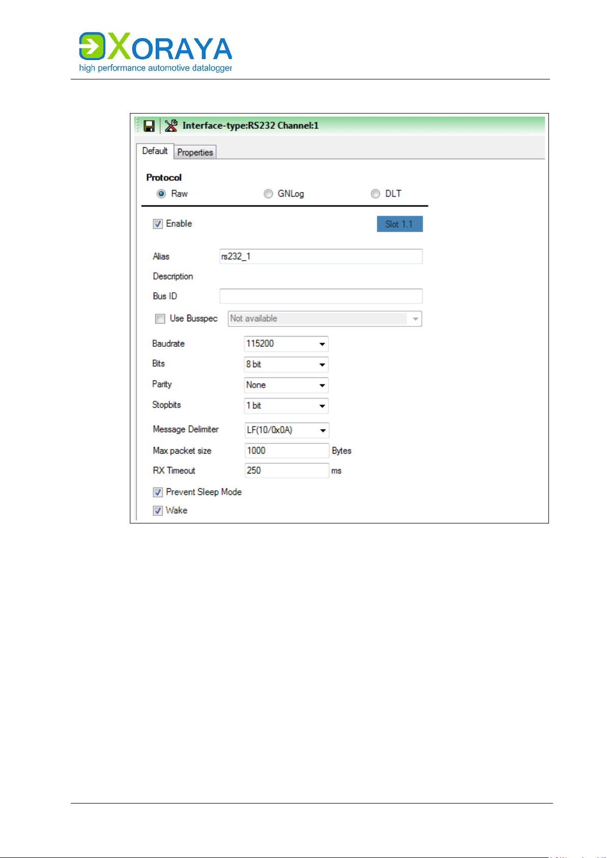
USER MANUAL
XORAYASUITE
RS-232:
71
Page 72

USER MANUAL
Setting
Description
Default
Protocol
Raw, GNLog or DLT
Raw
Enable
Turn on logging for this channel
On
Alias
Freely selectable channel name
rs232_# or
DLT#
Bus ID
Additional ID for subsequent evaluation
Use Busspec
Load configuration template provided by
the vehicle manufacturer
Off
DLT: 0 (None) to 6 (Verbose)
Trace state***
Send trace messages
Off
Verbose mode***
Off: Send only dynamic data
On: Send dynamic and static data
Off
Baudrate
Transfer rate (in bit/s)
57600, 115200, 230400
115200
Values: 5 bit, 6 bit, 7 bit, 8 bit
Parity
Parity check for error detection
Values: None, Odd, Even
None
Stopbits
Number of stop bits that mark the end of
Values: 1 bit, 2 bit
1 bit
stream**
Message Delimiter*
Delimiter that marks the end of a message
Values: LF(10/0x0A) = end of line, None
LF(10/0x0A)
Max packet size*
Maximum packet size (in Bytes)
1000
RX Timeout*
If no new character is received during this
250
Prevent Sleep Mode
ML-N4000 will not go into sleep mode as
long as there is activity on this channel
On
soon as there is activity on this channel
XORAYASUITE
Debug level** Detail level of the debug information
GNLog: 0 to 3 (max)
gnlog# or
GNLog: 2
DLT: 0 (None)
Values: 4800, 9600, 19200, 38400,
Bits Number of data bits of a data block
a data block
keep low level data
Underlying RS-232 data are saved Off
period (in ms), then the previously
received data are interpreted as completed
message
0: Function disabled
8 bit
Wake* ML-N4000 wakes up from sleep mode as
* Only for Raw **Only for GNLog and DLT ***Only for DLT
72
On
Page 73

USER MANUAL
Setting
Description
Default
Enable
Turn on logging for this channel
On
Alias
Freely selectable channel name
ethernet#
Bus ID
Additional ID for subsequent evaluation
Use Busspec
Load configuration template provided by the vehicle
manufacturer
Off
Prevent Sleep
Mode
ML-N4000 will not go into sleep mode as long as
there is activity on this channel
On
XORAYASUITE
Ethernet:
ORAYA ML-N4000 with BroadR-Reach/Base-T1 switch, there are
For X
additional settings available here.
Ethernet > Settings:
73
Page 74

USER MANUAL
1
Reset link
XORAYASUITE
BroadR-Reach/Base-T1 switch:
The Link state of each port is represented as a red or green traffic light.
Click (1) to reset the link.
In Data Sink switch operation mode, the data are only recorded.
In Pass Through mode, the BroadR-Reach ports are combined as pairs to
allow a bus connection between ECU and BroadR-Reach component, for
example a camera. Configure the paired ports of the BroadR-Reach switch
alternately to master and slave so that the data are routed in both
directions. The data are also recorded.
74
Page 75

USER MANUAL
Setting
Description
Default
Master / Slave
Mode of the BroadR-Reach port
Slave
Switch operation
Operation modes of the BroadR-Reach switch
via Ethernet
Pass
1
Add pre-filter
4
Increase pre-filter priority
2
Delete pre-filter
5
Decrease pre-filter priority
3
Save pre-filter
XORAYASUITE
A VLAN-ID is assigned to each port. During data recording, this ID is
inserted into the Ethernet frame as the outer VLAN tag, so the measurement
contains information on which port the data were received. You can change
the VLAN-ID for each port separately via the property brr_vlan_outer_vid# in
the category other.
mode
Pass Through: Data recording and forwarding
between port pairs
Data Sink: Only data recording
Pass Through / Data Sink (Allow single tagged
VLAN): Additional modes to enable DLT tracing
Through
Ethernet > Filter:
75
Page 76

USER MANUAL
XORAYASUITE
The filter is executed in two successive steps:
Configure pre-filters:
Pre-filter MAC address
Queue dispatching filter EtherType and VLAN
Click Add pre-filter (1).
Choose the Filter type (only MAC is available at the current
development stage).
Under Direction, choose if the filter applies to a participant who is
Source and/or Target.
Under Operator, choose if the filter is added to the whitelist (==) or the
blacklist (!=).
Specify the MAC address.
Click Save pre-filter (3).
Repeat as necessary for further pre-filters.
Priorities of pre-filters
Change the priorities of the pre-filters with the buttons
(4) and (5).
The X
ORAYASuite applies the first pre-filter from the top
that matches the condition. The other pre-filters are
ignored.
The ML-N4000 processes packet data in Online mode and HDD mode via the
so-called default-queue. In the stream-queue, only HDD mode recording is
possible, and streaming data are directly stored without creating statistics.
The queue dispatching filter compares EtherType and both VLAN tags
(InnerTag, OuterTag) of received Ethernet frames with the bytes specified
here. ( Set bits)
If all selected filter conditions are matched, the Ethernet frame is assigned
to the streaming data, otherwise to the packet data. If the Ethernet frame
contains no or only one VLAN tag, the filter conditions for the non-existing
fields are ignored.
Via Load presets, you can configure filter conditions in such way that either
all frames are assigned to streaming data (Streaming logging only) or all
frames to packet data (Packet logging only).
76
Page 77
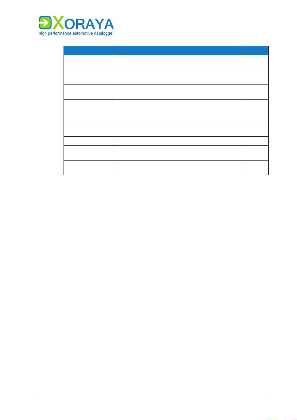
USER MANUAL
Setting
Description
Default
if matching
TPID (InnerTag)
Tag protocol identifier of the inner VLAN tag for
Ethernet frames (always 0x8100)
0x8100
TCI (InnerTag)
Expected result of the check on the inner VLAN tag
if matching
0x0
Values: 0x88A8, 0x9100, 0x9200, 0x9300
TCI (OuterTag)
Expected result of the check on the outer VLAN tag
if matching
0x0
NOT
Invert filter condition
Off
Enable packet
logging
Record filtered packet data
On
logging
EtherType Expected result of the check on the EtherType field
TPID (OuterTag) Tag protocol identifier of the outer VLAN tag for
XORAYASUITE
0x0
0x88A8
Ethernet frames
Enable streaming
Record filtered streaming data On
77
Page 78

USER MANUAL
XORAYASUITE
Ethernet protocols:
In this configuration section, you can add, update and delete GNLog and
DLT channels. Both protocols are recorded via the LAN host ports or the
BroadR-Reach interface.
78
Page 79

USER MANUAL
Setting
Description
Default
Enable
Turn on logging for this channel
Off
Alias
Freely selectable channel name
gnlog# or
DLT#
Bus ID
Additional ID for subsequent evaluation
Source
TCP (GNLog, DLT) or UDP (only DLT)
(DLT)
Use Busspec
Load configuration template provided by the
vehicle manufacturer
Off
Prevent Sleep
Mode
ML-N4000 will not go into sleep mode as long
as there is activity on this channel
On
Debug level
Detail level of the debug information
DLT: 0 (None) to 6 (Verbose)
GNLog: 2
Trace state*
Send trace messages
Off
On: Send dynamic and static data
VLan Id
Check box activates VLAN ID according to IEEE
Values: 1 to 4095
1
communication with the ECU
communication with the ECU
XORAYASUITE
IP address and port of the ECU
Default sets the port to 851 (GNLog) or 3490
GNLog: 0 to 3 (max)
DLT: 0 (None)
Verbose mode* Off: Send only dynamic data
802.1Q
IP address IP address which the ML-N4000 uses in the
IP mask Network mask which the ML-N4000 uses in the
* Only for DLT
Off
0.0.0.0
0.0.0.0
79
Page 80
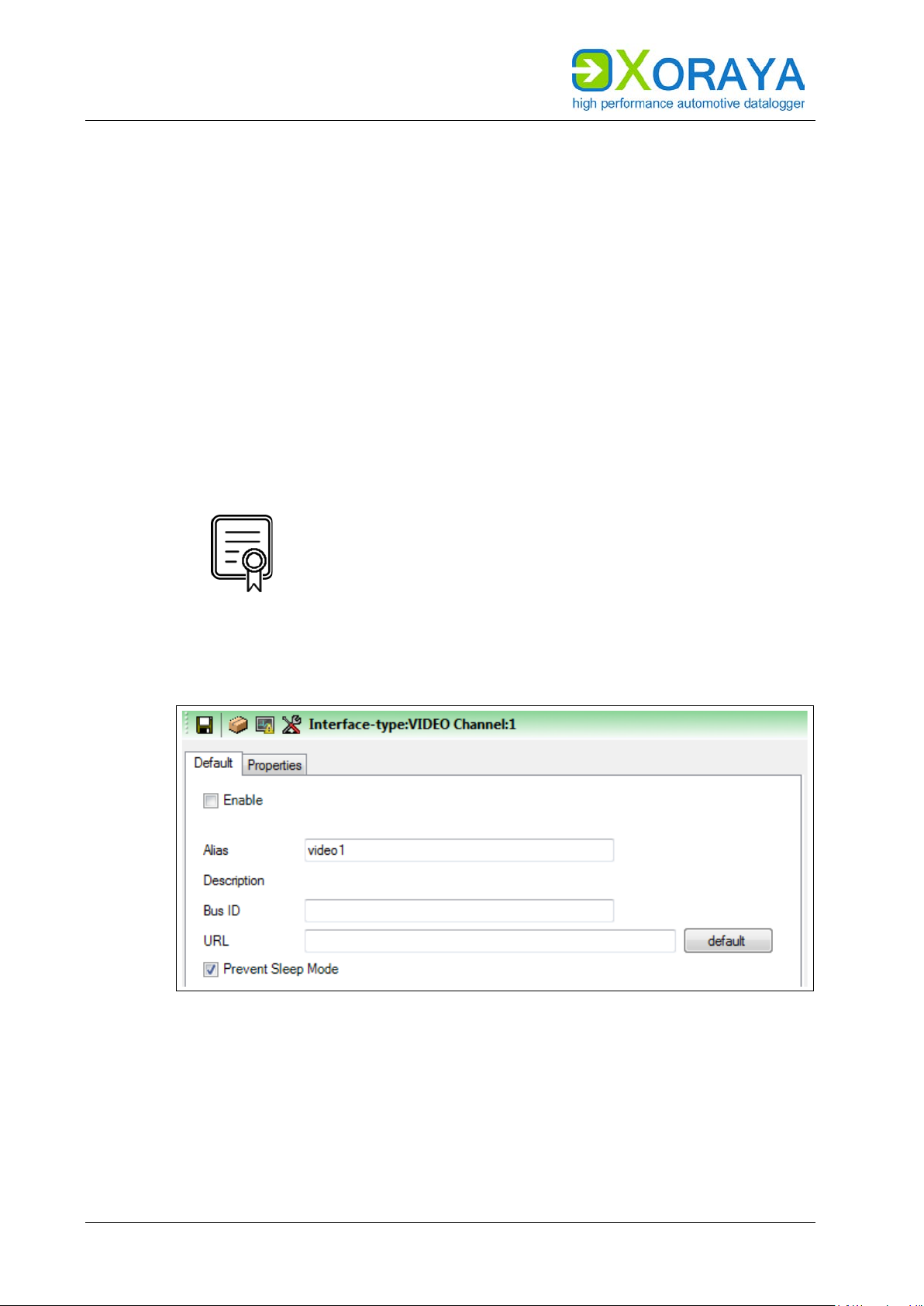
USER MANUAL
XORAYASUITE
VIDEO:
Connect camera:
Control video recordings:
Connect the camera to one of the Ethernet log interfaces (N).
( Connections and controls)
Connect another Ethernet log interface (N) to one of the LAN host ports
(H).
Connect another LAN host port (H) to the PC.
Create one or multiple signal-based triggers of the VIDEO interface.
or
Activate one or multiple trigger actions of the button interface that
effect the video recording. ( Button)
INTERFACE_NET_CAMERA
VIDEO > Settings:
This licence is required for video recordings.
Check in category Versions of system settings to verify
which licences are activated for your ML-N4000.
( Versions)
80
Page 81

USER MANUAL
Setting
Description
Default
Enable
Turn on logging for this channel
Off
Alias
Freely selectable channel name
video#
Bus ID
Text box Bus ID
Additional ID for subsequent evaluation
URL
To control an IP camera
camera
Mode
is activity on this channel
1
Add trigger
4
Delete trigger
2
Trigger type
5
Move trigger up
3
Edit trigger
6
Move trigger down
XORAYASUITE
default enters the sample configuration of a Basler
Prevent Sleep
ML-N4000 will not go into sleep mode as long as there
On
VIDEO > Trigger:
Here, you create conditions that trigger the following pre-defined actions:
Create replay (the video stream currently stored in the circular buffer is
saved permanently)
Take screenshot
Start Stream
Stop Stream
81
Page 82

USER MANUAL
XORAYASUITE
Configure triggers:
On the header of the desired trigger action, click Add trigger (1).
Select the desired Trigger type (2).
Create a single condition or multiple combined conditions for this
trigger. ( Create trigger conditions)
If required, repeat the above steps for further triggers.
Number of configurable triggers
You can configure a maximum of ten triggers per VIDEO
interface channel.
82
Page 83

USER MANUAL
1
Clear all settings
5
Open selection file
2
Edit CAN interface channel
6
Settings
3
Open A2L file
7
Traffic light for the bus load
4
Traffic light for the EPK check
XORAYASUITE
DiagCCP:
DiagCCP > Settings:
83
Page 84

USER MANUAL
Setting
Description
Default
Enable
Turn on logging for this channel
Off
Spy CCP
CCP mode
Off: Master
Off
Alias
Freely selectable channel name
ccp#
Bus ID
Additional ID for subsequent evaluation
Prevent Sleep
Mode
ML-N4000 will not go into sleep mode as long as
there is activity on this channel
Off
Source
Physical CAN channel to be used
Can_1 (can1)
A2L file
Description file, which is suitable for the ECU and
is loaded to configure the CCP connection
a (pre-)selection of the signals to be monitored
connection attempt
Data timeout
No data received for this period of time (in s)
leads to an error
10
XORAYASUITE
traffic
PROTOCOL_CCP
PROTOCOL_CCP_SPY
The available modes (Master, Spy) depend on the
activation of these licences.
Check in category Versions of system settings to verify
which licences are activated for your ML-N4000.
( Versions)
On: Spy (external communication is monitored,
no sending)
Selection file Signal filter file (XML, CFG or LAB), which contains
Retry max Maximum number of retries after unsuccessful
3
Meaning of the symbols for the physical CAN channels:
transmission-capable
transmission-capable, but currently set to passive
not transmission-capable
not enabled
Via Edit CAN interface channel (2) button, you can enable it, activate its
transmission capability or change its baudrate if necessary.
84
Page 85

USER MANUAL
A2L configuration:
Click Open A2L file (3) and select the description file that corresponds
with the ECU.
XORAYASUITE
The XORAYASuite reads the A2L file and configures the CCP
connection accordingly.
If Overwrite alias with ECU name under Settings (6) is activated,
Alias is also changed.
If supported by the A2L file, the XORAYASuite automatically runs an
EPK version check with the ECU and displays the result via the
Traffic light for the EPK check (4).
You can also execute this check manually via the EPK button.
Levels of the Traffic light for the EPK check (4):
green check successful
yellow check not possible
red check not successful
Signal configuration:
Click Open selection file (5) and select a suitable XML, CFG or LAB file.
or
Click Signal selection and select the signals manually. ( Filter)
The XORAYASuite calculates the expected percentage of the bus load
increase.
The result evaluation is displayed via the Traffic light for the bus
load (7).
Configure the levels of the Traffic light for the bus load (7):
Right-click on the traffic light and then on Edit traffic light settings for
this interface type.
Specify the percentage limit between green and yellow (standard: 50).
Specify the percentage limit between yellow and red (standard: 80).
Click OK.
85
Page 86

USER MANUAL
1
Show all signals
7
Export signals
2
Search box
8
Display CCP main settings
3
Refresh signal list
9
Add polling channel*
4
Display selected signals
10
Status of the signal definition file
5
Clear selected signals
11
Prescaler*
6
Import signals
XORAYASUITE
DiagCCP > Filter:
* Only if supported by the A2L file
Select signals for the DAQ measurement mode:
Select the check box of the signal (row) for the event channel (column).
or
Highlight one or multiple rows and right-click to activate these signals
simultaneously for one event channel.
Select signals for the polling measurement mode:
Click Add polling channel (9).
The button is inactive if the A2L file does not support polling.
In the row of the signal, select the polling cycle from the drop-down
list.
Filter signal list:
Enter the term or partial term in the search box (2) and click Refresh
signal list (3).
or
Click Display selected signals (4) to only display signals with selected
check boxes or selected polling cycle.
Clear signal list filter:
Click Show all signals (1).
86
Page 87

USER MANUAL
XORAYASUITE
To allow a later MDF export of the data without A2L file, generate a signal
definition file in the Other category and save it, optionally encrypted, on the
ML-N4000. ( Other)
Status of the signal definition file (10) displays the current state of the file
and changes its state by clicking:
not generated
saved on ML-N4000
saved encrypted on ML-N4000
not saved on ML-N4000
If supported by the A2L file, you can reduce the sampling rate of each event
channel by increasing the Prescaler (11).
87
Page 88

USER MANUAL
1
Add trigger
4
Delete trigger
2
Trigger type
5
Move trigger up
3
Edit trigger
6
Move trigger down
Trigger action
Description
ccp.start
Start CCP data recording
ccp.stop
Stop CCP data recording
XORAYASUITE
DiagCCP > Trigger:
Here, you create conditions that trigger the following actions:
Start and stop without trigger conditions
Even when you do not create trigger conditions, the CCP
recording, provided it is activated, starts and stops
automatically at the beginning or ending of the data
recording in online mode or HDD mode.
Configure triggers:
On the header of the desired trigger action, click Add trigger (1).
Select the desired Trigger type (2).
Create a single condition or multiple combined conditions for this
trigger. ( Create trigger conditions)
88
If required, repeat the above steps for further triggers.
Number of configurable triggers
You can configure a maximum of ten triggers per
DiagCCP interface channel.
Page 89

USER MANUAL
1
Show/hide A2L signals
4
Additional signals
2
Delete signal
5
Signal selection
3
Delete signal definition file
XORAYASUITE
DiagCCP > Other:
To allow a later MDF export of the data without A2L file, generate a signal
definition file as a reduced A2L file and save it, optionally encrypted, on the
ML-N4000.
Create and encrypt the signal definition file by selecting the check boxes
under MDF-Export of signals.
Add additional signals (4) to the signal definition file by selecting the
desired signals (5). ( Signal selection)
By clicking (1), you also display the signals which are imported from the A2L
file.
By clicking (2), you delete the selected signals and with (3) the whole signal
definition file.
89
Page 90

USER MANUAL
1
Add basic structure of the function
3
Execute function
2
Input data
XORAYASUITE
DiagCCP > Advanced:
90
This category displays an overview of the configured event channels and
allows the definition of a seed and key function for the encrypted
communication with the ECU.
Create and test the seed and key function:
Click Add basic structure of the function (1).
Insert the algorithm that corresponds with the ECU.
Define the Input data (2) to test the function.
Click Execute function (3).
The XORAYASuite calculates the output data (key) from the input data
(seed) and compares it with the key calculated by the ECU.
Page 91

USER MANUAL
1
Clear all settings
5
Open selection file
2
Edit interface channel
6
Settings
3
Open A2L file
7
Traffic light for the bus load
4
Traffic light for the EPK check
8
Engine RPM*
XORAYASUITE
DiagXCP:
DiagXCP > Settings:
* Only for angle-synchronous event channels
91
Page 92

USER MANUAL
Setting
Description
Default
Enable
Turn on logging for this channel
Off
Spy XCP
XCP mode
Off: Master
Off
Alias
Freely selectable channel name
xcp#
Bus ID
Additional ID for subsequent evaluation
Prevent Sleep
Mode
ML-N4000 will not go into sleep mode as long as
there is activity on this channel
Off
Source
Physical CAN or FlexRay channel to be used
Can_1 (can1)
A2L file
Description file, which is suitable for the ECU and
is loaded to configure the XCP connection
layer
layer descriptions
a (pre-)selection of the signals to be monitored
Retry max
Maximum number of retries after unsuccessful
connection attempt
3
leads to an error
XORAYASUITE
traffic
PROTOCOL_XCP_MASTER
PROTOCOL_XCP_SPY
PROTOCOL_XCP_ON_CAN
PROTOCOL_XCP_ON_FLEXRAY
The available modes (Master, Spy) and physical buses
(CAN, FlexRay) depend on the activation of these
licences.
Check in category Versions of system settings to verify
which licences are activated for your ML-N4000.
( Versions)
On: Spy (external communication is monitored,
no sending)
92
Transport
Selection file Signal filter file (XML, CFG or LAB), which contains
Data timeout No data received for this period of time (in s)
Selection if the A2L contains multiple transport
10
Page 93

USER MANUAL
XORAYASUITE
Meaning of the symbols for the available CAN or FlexRay channels:
transmission-capable
transmission-capable, but currently set to passive
not transmission-capable (only for CAN)
not enabled
Via Edit interface channel (2) button, you can enable it, activate its
transmission capability or change its baudrate if necessary.
A2L configuration:
Click Open A2L file (3) and select the description file that corresponds
with the ECU.
The XORAYASuite reads the A2L file and configures the XCP
connection accordingly.
If Overwrite alias with ECU name under Settings (6) is activated,
Alias is also changed.
If the A2L contains multiple transport layer descriptions, select the
layer from the appearing window.
You can change this selection afterwards via the drop-down list
Transport layer.
If the time value T7 is equal to 0, increase this value in the appearing
window to avoid protocol errors with the ECU.
You can change this value and all the other time values in the category
Advanced. ( Advanced)
If supported by the A2L file, the XORAYASuite automatically runs an
EPK version check with the ECU and displays the result via the
Traffic light for the EPK check (4).
You can also execute this check manually via the EPK button.
Levels of the Traffic light for the EPK check (4):
green check successful
yellow check not possible
red check not successful
93
Page 94

USER MANUAL
XORAYASUITE
Signal configuration:
Configure the levels of the Traffic light for the bus load (7):
Click Open selection file (5) and select a suitable XML, CFG or LAB file.
or
Click Signal selection and select the signals manually. ( Filter)
The XORAYASuite calculates the expected percentage of the bus load
increase.
The result evaluation is displayed via the Traffic light for the bus
load (7).
If angle-synchronous (RPM-dependent) event channels are used, select
the Engine RPM (8), which influences the bus load calculation.
Right-click on the traffic light and then on Edit traffic light settings for
this interface type.
Specify the percentage limit between green and yellow (standard: 50).
Specify the percentage limit between yellow and red (standard: 80).
Click OK.
94
Page 95

USER MANUAL
1
Show all signals
7
Export signals
2
Search box
8
Display XCP main settings
3
Refresh signal list
9
Add polling channel*
4
Display selected signals
10
Status of the signal definition file
5
Clear selected signals
11
Prescaler*
6
Import signals
12
Change column order
XORAYASUITE
DiagXCP > Filter:
* Only if supported by the A2L file
Select signals for the DAQ measurement mode:
Select the check box of the signal (row) for the event channel (column).
or
Highlight one or multiple rows and right-click to activate these signals
simultaneously for one event channel.
Select signals for the polling measurement mode:
Click Add polling channel (9).
The button is inactive if the A2L file does not support polling.
In the row of the signal, select the polling cycle from the drop-down
list.
Filter signal list:
Enter the term or partial term in the search box (2) and click Refresh
signal list (3).
or
Click Display selected signals (4) to only display signals with selected
check boxes or selected polling cycle.
Clear signal list filter:
Click Show all signals (1).
95
Page 96

USER MANUAL
XORAYASUITE
To allow a later MDF export of the data without A2L file, generate a signal
definition file in the Other category and save it, optionally encrypted, on the
ML-N4000. ( Other)
Status of the signal definition file (10) displays the current state of the file
and changes its state by clicking:
If supported by the A2L file, you can reduce the sampling rate of each event
channel by increasing the Prescaler (11).
The column order of the event channels is adjustable via the drop-down lists
(12).
not generated
saved on ML-N4000
saved encrypted on ML-N4000
not saved on ML-N4000
96
Page 97

USER MANUAL
1
Add trigger
4
Delete trigger
2
Trigger type
5
Move trigger up
3
Edit trigger
6
Move trigger down
Trigger action
Description
xcp.start
Start XCP data recording
xcp.stop
Stop XCP data recording
XORAYASUITE
DiagXCP > Trigger:
Here, you create conditions that trigger the following actions:
Start and stop without trigger conditions
Even when you do not create trigger conditions, the XCP
recording, provided it is activated, starts and stops
automatically at the beginning or ending of the data
recording in online mode or HDD mode.
Configure triggers:
On the header of the desired trigger action, click Add trigger (1).
Select the desired Trigger type (2).
Create a single condition or multiple combined conditions for this
trigger. ( Create trigger conditions)
If required, repeat the above steps for further triggers.
Number of configurable triggers
You can configure a maximum of ten triggers per
DiagXCP interface channel.
97
Page 98

USER MANUAL
1
Show/hide A2L signals
4
Additional signals
2
Delete signal
5
Signal selection
3
Delete signal definition file
XORAYASUITE
DiagXCP > Other:
To allow a later MDF export of the data without A2L file, generate a signal
definition file as a reduced A2L file and save it, optionally encrypted, on the
ML-N4000.
Create and encrypt the signal definition file by selecting the check boxes
under MDF-Export of signals.
Add additional signals (4) to the signal definition file by selecting the
desired signals (5). ( Signal selection)
By clicking (1), you also display the signals which are imported from the A2L
file.
By clicking (2), you delete the selected signals and with (3) the whole signal
definition file.
98
Page 99

USER MANUAL
1
Add basic structure of the function
3
Execute function
2
Input data
XORAYASUITE
DiagXCP > Advanced:
This category consists of the following elements:
Overview of the configured event channels
Timeout values (changeable)
FlexRay buffer configuration (partly changeable)
Mapping of the FlexRay buffers to the event channels (changeable)
Definition of a seed and key function for the encrypted communication
with the ECU
99
Page 100

USER MANUAL
XORAYASUITE
Create and test the seed and key function:
Click Add basic structure of the function (1).
Insert the algorithm that corresponds with the ECU.
Define the Input data (2) to test the function.
Click Execute function (3).
The XORAYASuite calculates the output data (key) from the input data
(seed) and compares it with the key calculated by the ECU.
100
 Loading...