

Digital UHF Wireless System
Model XDS95
Users Guide
Includes easy setup instructions for single and multisystem operation
Digital Wireless Systems
X2 Digital Wireless Systems
4630 Beloit Drive, Suite 20
Sacramento CA 95838 U.S.A.
Phone: (916) 779-1040
Fax: (916) 779-1041
Web Site
www.x2digitalwireless.com

XDS95 Owners Manual Version 1.1 December 11, 2006 9:30 AM

...................................... 1
................................................................................. 1
........................................................................... 1
.......................................... 2
................................................................ 2
............................................................. 2
........................... 3
.................................................................................. 3
........................................................... 3
............................................................... 3
.............................................................................. 3
.......................................................... 3
............................................................... 3
....................................................................... 3
.............................................. 4
............................................................................. 4
....................................................... 5
................... 5
..................................................................... 5
...................................................................... 6
.......................................................................... 6
................................................................................... 7
........................................................................................... 8
Contents
Chapter 1. Introduction to the XDS95
About the XDS95
System Components
Chapter 2. XDS95 System Features
XDR1 Digital UHF Receiver
XDT1 Digital UHF Transmitter
Chapter 3. Operating Your XDS95 System
Receiver Set Up
Power Up Procedure
Channel Selection
Transmitter Set Up
Power Up Procedure
Channel Selection
Connecting the System
Chapter 4. Additional Information
Advanced Features
Multi-system Operation
DigiScan™ Automatic Frequency Scan Mode
Optimizing Performance
Battery Life Information
Warranty Information
FCC Statement
Specifications
iii

Created specifically for performing and recording musicians who demand
to be untethered without compromising their sound, the XDS95 24-bit
digital wireless system delivers your tone and performance with the
sound and feel of a direct wire connection.
X2's proprietary digital technology provides superior fidelity while the XDS95’s "stomp-box"
style receiver houses a micro-processor that selects the digital data stream from among the
four internally mounted Q-diversity™ antennas to eliminate dropouts and interference
including DTV. You’ll enjoy the sound and performance of a direct wire connection free from
compander ICs and the associated 'pumping' and 'breathing' that squashes your tone, and
other problems associated with analog wireless technology.
Operating the system is unlike any wireless you've tried before. Simply connect the transmitter to the source via the 1/8" threaded-collar locking connector and the "stomp-box" style
receiver to your amplifier, mixer or pedal-board. Then power up making sure the transmitter
and receiver are set to the same channel. That's it. You're ready to go! No knobs to adjust
and no antennas to loose or break mean you're up and running in the time it would take to
connect a cable.
About the XDS95 Digital Wireless System
All of this sound and performance is provided to you with an incredible feature set including:
• 24-bit digital converters yield 117 dB dynamic range to capture your most expressive performances
• Frequency Clear™ UHF Digital - a proprietary digital signal on a 900 MHz UHF carrier for
freedom from multi-pathing and interference, including DTV
• Five user-selectable channels (all five are fully compatible for simultaneous use)
• Auto-DigiScan™ to confidently select an open channel
• Frequency response all the way down to 20 Hz for truly thundering lows
• Stereo 1/4" output for instrument and full-bandwidth or 'tuner out' applications
• Five segment LED display (battery status, link status, audio level, RF level and channel)
With the XDS95 Digital UHF Wireless System you'll have the freedom and sound to deliver
your most expressive performance every time without any hassles or complicated setup
procedures.
To familiarize you with your new digital wireless system, we suggest that you read through
this entire operation manual.
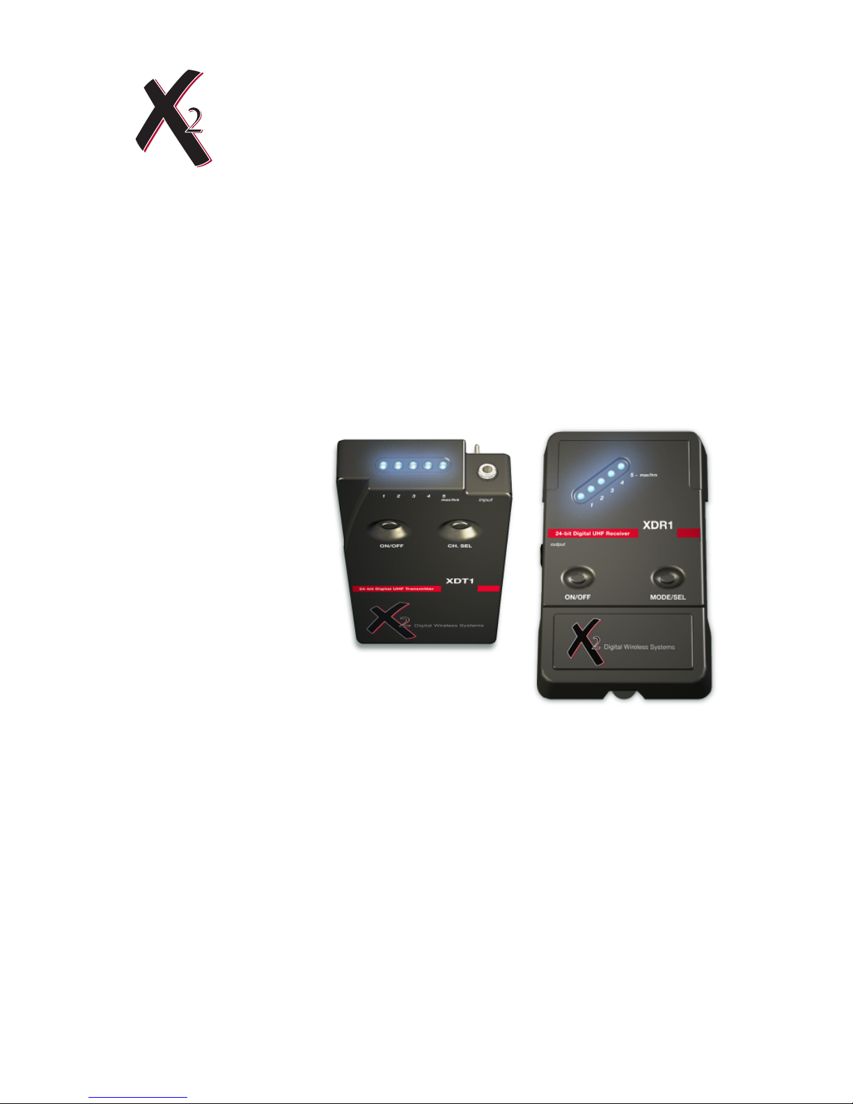
System Components
System includes:
• XDR1 Digital UHF Receiver
• XDT1 Digital UHF Transmitter
• 2 9v Alkaline Batteries
• 1/4” to 1/8” locking connector instrument cable
Optional Accessories:
• XAC2 (9V Power supply for XDR1)
Introduction to the XDS95 Digital UHF Wireless
1
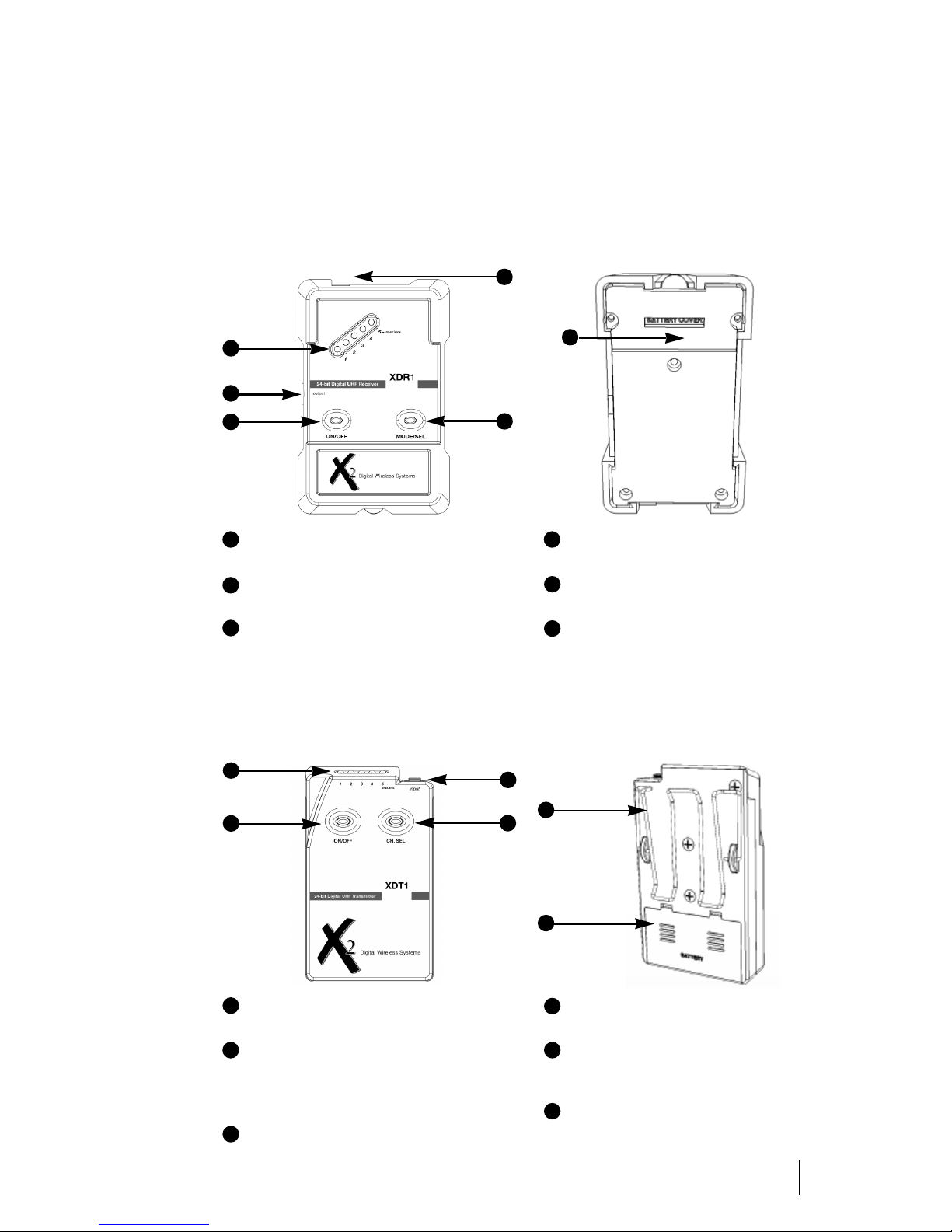
LED Display
• See system setup on page 3.
1/4” Mono/Stereo Output
• See system setup on page 3.
Power Switch
• Press once to turn the power to the
receiver on, and once more to turn the
power off.
3
5
1
AC Adapter Jack (Adapter is optional)
• 9V 300mA
Mode/Channel Select Button
• See system setup on page 3.
9V Battery Compartment
• Battery compartment is secured with
two screws.
4
2
1
XDS95 Digital UHF System Features
5
2
XDR1 Digital UHF Receiver
XDT1 Digital UHF Transmitter
6
6
4
3
3
1
2
4
LED Display
• See system setup on page 4.
Power Switch
• Press once to turn the power to the
transmitter on, and once more to turn the
power off.
1/8” Mono Instrument Input (cable included)
• 1/4” to 1/8” locking connector.
Mode/Channel Select Button
• See system setup on page 4.
Metal Belt Clip
• Fastens transmitter securely to belt
or guitar strap.
9V Battery Compartment
• Battery compartment snaps in place.
2
5
5
6
4
6
2
3
1

Power Up Procedure
Press on/off button to turn unit on. LEDs will cycle blue-redblue on power up sequence. Once unit is powered on the unit
will display current channel number with a blue LED and battery life with a red led.
The unit will automatically scan for your digital RF signal. This
is indicated by the blue LEDs cycling back and forth 1-5 then
5-1. After each cycle, the unit will stop on the current red batt
life LED then blink the current blue channel LED. The unit will stay in this mode until a
transmitter is turned on and transmitting on the same channel. Once the link is established
and the receiver is receiving data, the unit will display current channel number with a blue
LED and battery life with a red LED by continually toggling between the two LEDs.
As the user inputs audio into transmitter and sends it to the receiver unit, the LEDs on the
receiver become an audio level indictor. Blue LEDs are displayed from left to right as the
audio level increases. LED #5 will light red during audio display if the unit’s input reaches a
max level. After a few seconds pause in audio input the unit switches back to channel/battery display mode.
Channel Selection
There are 5 different frequency
channels which you can choose
to transmit and receive data, they
are labeled 1-5 on both transmitter and receiver. In order to operate on any one of these channels,
you must have both the transmit-
ter and receiver on the same
channel number. In order to change the receive frequency, push the channel button. The
unit will then increment and display the channel number with a blue LED each time the
user presses the button down. Continue this until the desired channel number is reached.
The unit will then go back to the mode displaying battery life and channel number.
Receiver Battery Metering
The battery is displayed on the receiver as follows: LED
#5(furthest to the right looking at the front of the unit) means
5hrs or greater of batt life remaining. As the battery expires the
unit will change the red LEDs to #4 for 4hrs, #3 for 3hrs, etc..
Once the unit has less than 1hr left of battery life the #1 LED
will then blink at a high rate until the battery expires. This
alerts the user to the need of battery replacement.
Power Down Procedure
To turn the unit off press and hold the on/off switch until the LEDs flash a red/blue alternating pattern then release the on/off button the unit will then power down. All LEDs off indicate
power down is complete.
Setting Up Your Receiver
3

Power Up Procedure
Press on/off button to turn unit on. LEDs will cycle blue-redblue on power up sequence.Once unit is powered on the unit
will display current channel number with a blue LED and battery life with a red led by continuously toggling between the
two LEDs.
As the user inputs audio into the unit the LEDs automatically
become an audio level indictor where blue LEDs are displayed from left to right as the audio level increases. LED #5 will light red during audio display if the units input reaches a maximum level. After a few seconds pause in audio input
the unit switches back to channel/battery display mode.
Channel Selection
There are 5 different frequency channels which you can
choose to transmit and receive data, they are labeled 1-5 on
both transmitter and receiver. In order to operate on any one
of these channels, you must have both the transmitter and
receiver on the same channel number. In order to change the
transmit frequency push the channel button, the unit will then
increment and display the channel number with a blue LED
each time the user presses the button down. Continue this
until the desired channel number is reached. The unit will then go back to the toggling LED
mode to display battery life and channel number.
Transmitter Battery Metering
The battery is displayed on the transmitter as follows: LED #5
(furthest to the right looking at the front of the unit) means
5hrs or greater of battery life remaining. As the battery expires
the unit will change the red leds to #4 for 4hrs, #3 for 3hrs,
etc.. Once the unit has less than 1hr left of battery life the #1
LED will then blink at a high rate until the battery expires. This
alerts the user to the need of battery replacement.
Power Down Procedure
To turn the unit off press and hold the on/off switch until the LEDs flash a red/blue alternating pattern then release the on/off button. The unit will then power down. All LEDs off indicate power down is complete.
Connecting the System
Plug your instrument into the transmitter with the provided cable. Next, connect the output
of the receiver to the input of your effects pedal, amplifier, recording device, etc.. When
using a standard 1/4” (mono) cable, the receiver will output audio signal optimized for
instrument applications. When using a stereo 1/4” (TRS) cable, the tip sends instrument
out, the sleeve sends full-bandwidth signal. This can be used as a “tuner out” or “direct out”
for interfacing with a variety of devices. PLEASE NOTE: when using “full bandwidth” for
typical instrument/amplifier setups there will be a noticeable increase in high frequency
response. High frequencies are not boosted by the system, rather, they are allowed to
“pass through”.
Setting Up Your Transmitter
4

Multi-system Operation
Up to five systems can operate simultaneously. In situations where it is necessary to have
more than one person wireless, each transmitter and receiver combination must be set to the
same channel. Set the first system to transmit and receive on channel “one”, the second system to transmit and receive on channel “two”... and so on.
DigiScan™ Special Receiver Power Up Mode
While holding down the channel select button on the receiver, push the on/off button and
release. Continue to hold the channel select button until the LEDs are all solid red. Then
release the channel select button. The unit will now do a RF scan on all 5 frequencies.
While in this mode the receiver will continue to scan and report. If the channel has no RF
signal then a blue LED will light for the corrosponding channel number. If there is currently
RF in the channel the LED will be red. Blue LEDs mean channel is clear red means the
channel is not clear. To enter regular operating mode push and hold down the on/off button
until the unit enters the normal mode.
Optimizing Your Wireless Performance
Place the receiver on or near the desired amplification system, pedalboard or with your
effects pedals. FOR BEST RESULTS, PLACE RECEIVER HIGH ABOVE ANY OBSTRUCTIONS, as the system works best when transmitter and receiver are in line of sight.
Battery Life Information
Fresh Alkaline batteries should last about ~12 hours in the XDT1 and ~8 hours in the
XDR1, NiCad rechargeable batteries will only last about 4.5 hours. Standard batteries are
not recommended. THE BATTERY HOUR DISPLAY WILL ONLY BE ACCURATE FOR
ALKALINE BATTERIES. The battery life is calculated inside the each component and displayed in 1 hour increments. Upon power up the battery info will take about one minute to
stabilize, the battery gauge is then accurate within + or - 30 min. You may use batteries
until they are completely drained without affecting the performance of the unit in any way.
Warranty Information
X2 will repair or replace any defective system within the first two years free of charge. X2 will
cover 2-day return shipping costs in the continental United States. This warranty is transferrable, but does not cover abused systems. Terms and conditions subject to change without notice. Please retain a copy of your dated sales receipt for proof of warranty status
should repairs become necessary.
Warning:
Changes or modifications not expressly approved in writing by X2 Corporation may void the
users authority to operate this equipment.
This device complies with part 15 of the FCC rules. Operation is subject to the following
two conditions: (1) This device may not cause harmful interference, and (2) this device
must accept any interference received, including interference that may cause undesired
operation.
This Class B digital apparatus complies with Canadian ICES-003.
Cet appareil numérique de la classe B est conforme à la norme NMB-003 du Canada.
Additional Information
5

Symptom Cause Solution
No sound
System not turned on. Improper
connection or improper channel
selection.
Check that the system is powered
on. Check that the transmitter and
receiver are set to the same operating channel. Check that the receiver
is receiving data. Check that the
source is operating correctly. Check
that the receiver displays audio
level. Check connections.
Intermittent sound or
distorted sound
Improper source performance.
Improper connection. Multiple
transmitters are set to the
same operating channel.
Transmitter has gone out of
range. Transmitting through
metal wall. Unknown source of
RF in local vicinity.
Check source. Check connections.
Turn your transmitter off. Check to
see if receiver still displays data
being received. If so, locate and
either turn off or switch channels on
extra transmitter. Adjust receiver
positioning closer to transmitter.
Check that other local communication systems are not interfering with
your performance. They will most
likely be within close proximity to
receiver.
Troubleshooting
Refer All Servicing to X2
We believe that the XDS95 is one of the most reliable wireless systems that can be made
using current technology, and should provide years of trouble-free use. However, should
problems occur, DO NOT attempt to service the unit yourself. Service on this product
should only be performed by X2. THERE ARE NO USER SERVICEABLE PARTS INSIDE.
Obtaining Repair Service
Before contacting X2, check over all your connections, and make sure you’ve read the
manual. Your X2 dealer may be able to offer further assistance. If the problem persists, call
X2 at 916-779-1040 and request the customer service department. Talk the problem over
with one of our technicians; if necessary, you will be given a return authorization (RA) number and instructions on how to return the unit. All units must be shipped prepaid and COD
shipments will not be accepted. For prompt service, indicate the RA number on the shipping label. Tape a note to the top of the unit describing the problem, include your name and
phone number where X2 can contact you if necessary, as well as instructions where you
want the system returned. X2 will pay for 2nd-day shipping back to you on any repair covered under the terms of this warranty.
Service address for customers in the USA:
X2 Digital Wireless Systems
4630 Beloit Drive, Suite 20
Sacramento, CA 95838
(916) 779-1040
6

Overall System Specifications
Transmission Format: X2 proprietary digital audio transmission
Frequency Response: 20 Hz - 12 kHz
Audio Dynamic Range: >117 dB
Distortion: 0.03% THD
RF Carrier Frequency: 902 MHz to 928 MHz, FSK
Selectable Frequencies: Five
RF Output Power: 10mw
Audio Output Level: Unity gain with transmitter input
Polarity: Positive voltage at input yields positive voltage at output
Transmission Range: >150 feet line-of-sight (may vary due to local conditions)
FCC Approval: Part 15 approved, no user-license required
XDT1 Transmitter Specifications
A/D Conversion: 24-bit Delta Sigma, 128 times over sampling
Input Impedance: 1.3 MΩ
Connectors: 1/8" Unbalanced locking connector
Controls: Power On/Off, Channel Select
LED Display: Five segment - Power On, Channel, Battery Life, Audio
Level Meter
Dimensions: 2.4" W x .66" D x 4" H
Battery Life: Switching power supply, ~12 Hours (9v alkaline)
Weight: .25 lbs (with 9v battery installed)
XDR1 Receiver Specifications
D/A Conversion: 24-bit Delta Sigma, 128 times over sampling
Output: 2.12V RMS (Unbalanced: 1.8KΩ)
Connectors: 1/4" Unbalanced stereo output, tip= instrument voicing,
sleeve= full bandwidth
LED Display: Five segment - Power On, Data Link, Channel, Battery
Life, Audio Level Meter, RF Strength
Controls: Power On/Off, Channel/Mode Select
Dimensions: 3.078" W x 1.17" D x 4.7" H
Power Requirements: 9V DC via battery or optional AC power supply
Battery Life: Switching power supply, ~8 Hours (9v alkaline)
Weight: .45 lbs (with 9v battery installed)
Specifications
7


© 2006 X2 Digital Wireless Systems, Inc. All rights reserved.
Q-Diversity™,FrequencyClear™ and DigiScan™ are trademarks of X2 Corporation.
XDS95 PATENTS PENDING.
 Loading...