

Page 1
PANIC PANIC
ARM DISHOME ARM
ARM DISAWAY ARM
SECURITY
LIGHT
ON OFF
A
I
EM
O
C
GK
•
•
•
•
•
•
•
•
INSTANTDELAY
BRIGHT DIM
ENTRY
DOOR/WINDOW SENSOR
MOTION DETECTOR
™
Monitor Plus
Supervised Security System
With Digital Central Station Communicator
PANIC
ZONES
9
1
10
2
3
11
4
12
5
13
6
14
7
15
8
16
ARM AC POWERMONITOR BATTERY LOW
AWAY - ARM - HOME
ZONES 9-16
BYPASS
ON - LIGHTS - OFF
1st Draft
®
™
Lamp Module
BATTERY
ARM
DISARM
LIGHTS
ON
LIGHTS
OFF
1
•
•
15
3
•
513
•
•
711
•
•
9
UNIT
A
•
•
O
C
•
•
EM
•
•
GK
•
•
I
HOUSE
PANIC
Monitored Security System, Model DC8700P
Page 2
READ THIS FIRST
This equipment generates and uses radio
frequency energy, and if not installed and used
properly, that is, in strict accordance with the
manufacturers instructions, may cause
interference to radio and television reception. It
has been type tested and found to comply with
the limits for remote control security devices in
accordance with the specifications in Sub-Parts
B and C of Part 15 of FCC Rules, which are
designed to provide reasonable protection against
such interference in a residential installation.
However, there is no guarantee that interference
will not occur in a particular installation. If this
equipment does cause interference to radio or
television reception, which can be determined by
unplugging the equipment, try to correct the
interference by one or more of the following
measures.
• Reorient the antenna of the radio/TV
experiencing the interference.
• Relocate the console with respect to the
radio/TV.
• Move the console away from the radio/TV.
• Plug the console into an outlet on a different
electrical circuit from the radio/TV experiencing
the interference.
If necessary, consult your local X10 Dealer for
additional suggestions.
Your console’s telephone dialer is designed to
conform to federal regulations, and you can
connect it to most telephone lines. However, each
telephone or telephone device that you connect
to the telephone line draws power from the
telephone line. We refer to this power draw as the
device’s ringer equivalence number, or REN.
If you use more than one telephone or other device
on the line, add up all the RENs. If the total is
more than five, your telephones might not ring. In
rural areas, a total REN of three might impair
ringer operation. If ringer operation is impaired,
remove one of the devices from the line.
Note: You must not connect your console to:
• Coin-operated systems
• Party-line systems
• Most electronic key telephone systems
Your console’s telephone dialer complies with Part
68 of FCC Rules. You must, upon request, provide
the FCC registration number and the REN to your
telephone company. Both numbers are shown on
the bottom of the console.
The telephone portion of your security console
has been tested and found to comply with all
applicable UL and FCC standards.
In the unlikely event that your console causes
problems on the telephone line, the telephone
company can disconnect your service. The
telephone company attempts to notify you in
advance. If advance notice is not practical, the
telephone company notifies you as soon as
possible and advises you of your right to file a
complaint with the FCC.
Also, the telephone company can make changes
to its lines, equipment, operations, or procedures
that could affect the operation of this console. The
telephone company notifies you of these changes
in advance, so you can take the necessary steps
to prevent interruption of your telephone service.
Note: The security functions of this system have
not been tested by Underwriters Laboratories.
CONTENTS
INTRODUCTION ...................................................................................................4
SETTING UP THE CONSOLE ..............................................................................5
SETTING UP REMOTE CONTROLS ................................................................... 8
SETTING UP DOOR/WINDOW SENSORS ......................................................... 9
SETTING UP MOTION SENSORS.....................................................................12
SETTING UP REMOTE MODULES ................................................................... 15
SETTING UP FOR THE MONITORING STATION ..............................................17
USING THE SYSTEM .........................................................................................18
TURNING LIGHTS ON AND OFF REMOTELY ..................................................23
REPLACING BATTERIES ................................................................................... 24
TO CLEAR ALL SENSORS AND REMOTES FROM THE CONSOLE ...............25
TROUBLESHOOTING ........................................................................................26
32
Page 3
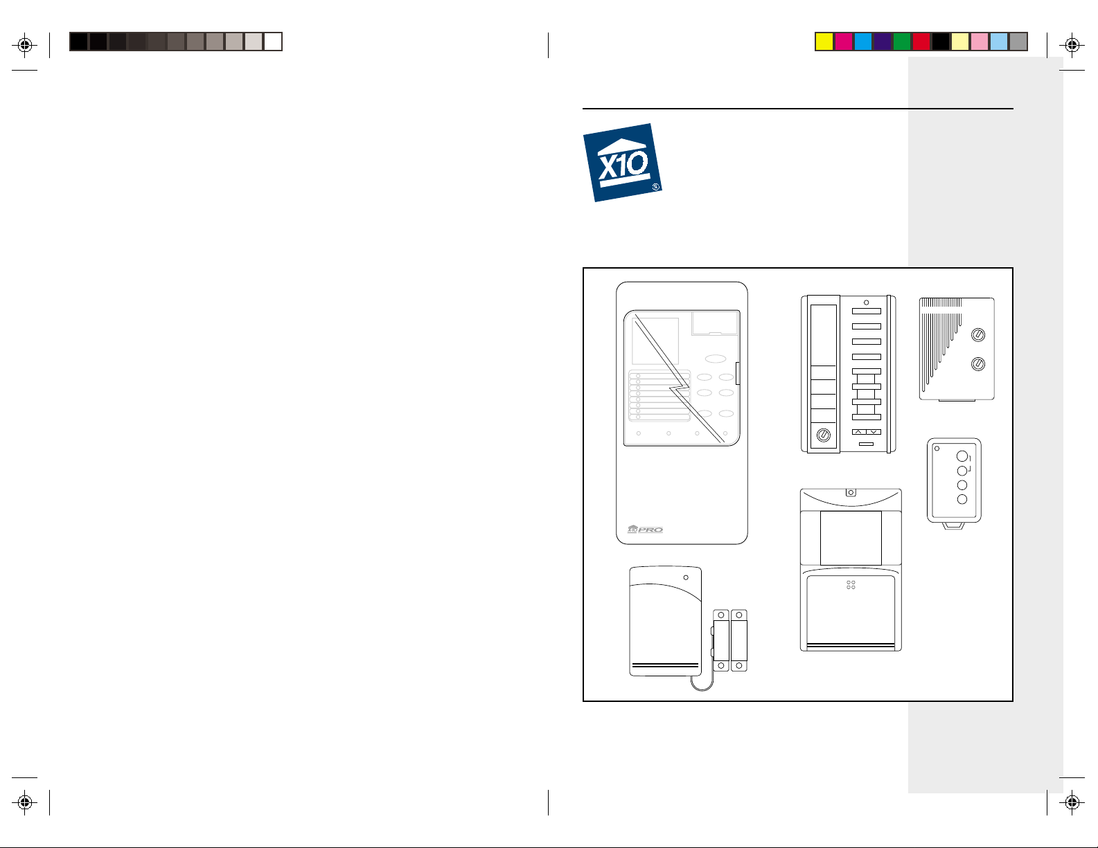
SETTING UP THE CONSOLEINTRODUCTION
Your X10 Powerhouse Monitor Plus
Security System lets you feel secure.
The system includes a security console
with a digital communicator that
connects to a professional digital
monitoring station in the event of a break
in. The system includes two Door/
Window Sensors, a Motion Sensor, a
Lamp Module, and two Remote
Controls: one hand held, one keychain.
Features:
Quick Installation: The Monitor Plus
security system installation is a snap.
The system is easy to install and use.
Wireless Sensors: The Door/Window
Sensors, and Motion Sensor are
completely wireless and communicate
to the base console via radio frequency.
Built in Digital Communicator: Calls
the monitoring station in the event of a
break in.
Fully expandable: You can protect up
to 16 zones with your security system,
plus you can control lights and
appliances by Remote Control, to start
a complete home automation system.
Panic Alarm: Lets you sound the alarm
without calling the monitoring station.
Automatic lighting control: When the
Monitor Plus Security System is armed,
an automatic timer can be put into action
which turns lights, stereos, TVs, etc. on
and off at random times to make your
home look and sound lived in.
X10 Home Automation compatible:
Adding X10 Home Automation products
such as Lamp Modules, Appliance
Modules, and Wall Switches, etc., is
easy with this system, since it is already
configured to control the full range of
X10 Home Automation products.
Self checking, fully monitored
system: Every sensor installed is self-
checking, and if any fail to report in to
the base console at the correct time
interval, the sensor's zone indicator on
the alarm console flashes to alert you.
If you then try to arm the system, a
special warning tone is sounded, and
you must press a button to acknowledge
and bypass the warning before you can
complete the arming sequence.
Battery backed-up console: If the
power fails or is cut, the house lights
will, of course, stop working - but the
security system doesn't, with all
features including telephone dialing and
alarm siren still ready for action using
easy to replace AA alkaline backup
batteries in the console. An indicator on
the console warns you when the
batteries need changing.
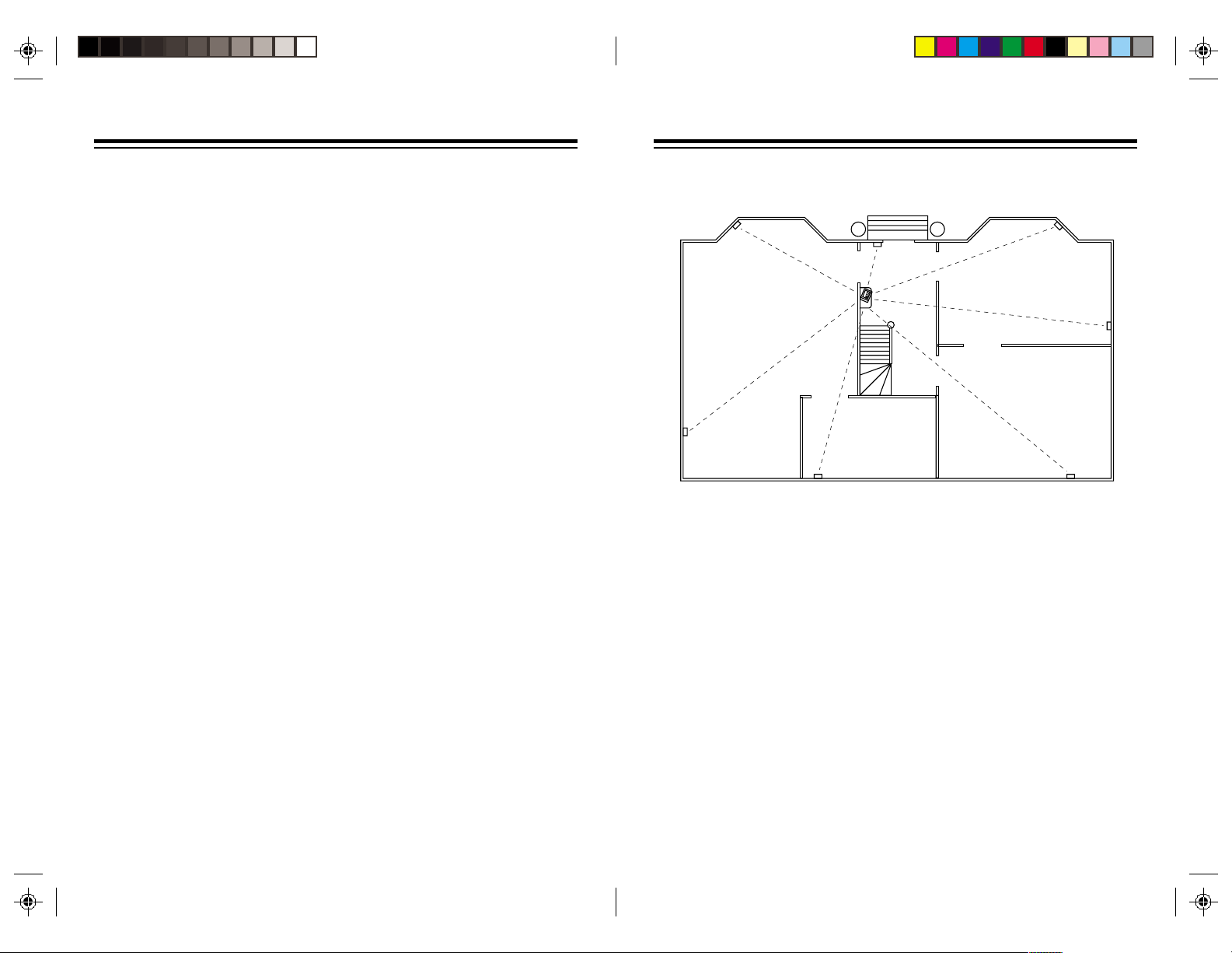
Choosing a location for the
console
Living Room
Study
Before you select a location for the
Monitor Plus console, think of the areas
in your home where you would be most
likely to use the Remote Controls, Door/
Window Sensors, and Motion Sensors.
Select a location that is central to those
areas and that is within the console’s
range (up to 100 feet).
Dining Room
Hallway
Kitchen
Here are some other things to consider
when choosing the console’s location:
• It must be close to a modular
telephone jack so you can easily
connect the telephone dialer.
• The console’s loud alarm might
frighten you if you trip it while you are
next to it, so it is best to place the
console in a large open area (like a
living room). But, you should also
place it close to a window so
neighbors are more likely to hear the
alarm.
54
Page 4
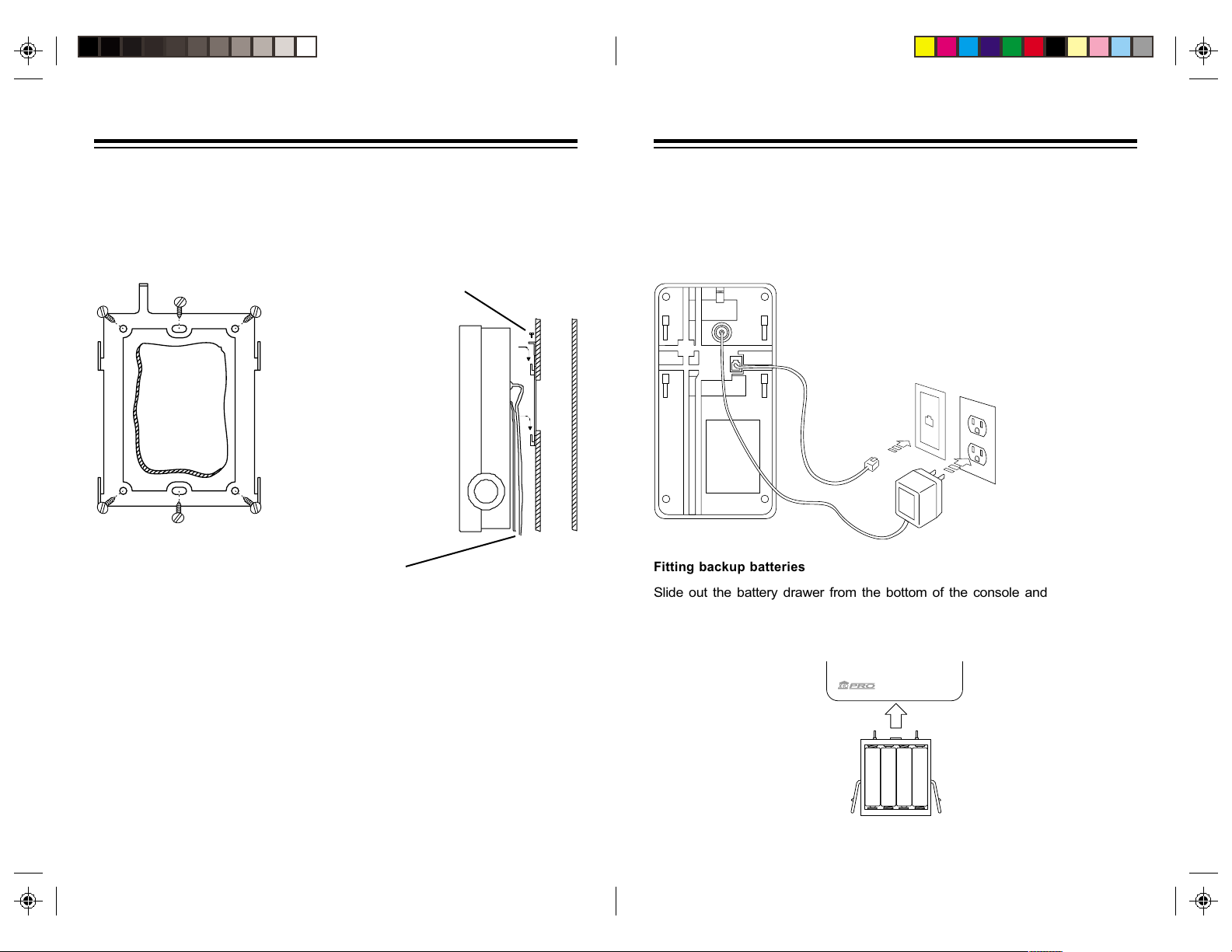
INSTALLATION
Mounting the Console
If desired, the Security Console can be wall mounted using the included mounting
bracket. Attach the mounting bracket to a standard electrical wall box, which you
can purchase at most hardware stores. Hooks on the bracket locate in slots at the
back of the console. A small screw is provided that can be used to prevent the unit
from being lifted off the hooks.
Slide the Console
onto the hooks on
the bracket and
attach the screw.
The power plug
on the back of
the Console will
protrude into the
wall box and you
can feed the
cables down
through the
Attach the mounting bracket to a
standard electrical wall box.
recesses in the
back of the
Console.
Or you can simply place the console on a flat surface and connect the telephone
cord and power supply as shown on the next page.
Warning: To reduce the risk of electric shock, never plug a telephone cord into a
telephone line jack until the other end of the cord is plugged into the telephone
device.
If you already have a phone plugged into the jack, use the included 'T' adapter to
plug the console and telephone into the same jack.
If your telephone wiring does not have a modular jack, you can:
• Update the wiring yourself. Most good electrical stores sell adapters to convert
older wiring methods to modular wiring.
• Have the telephone company update the wiring for you.
Note: The telephone company charges to install the necessary jacks.
The USOC number of the jacks to be installed is RJ11C (or RJ11W for a wall plate
installation).
You can use the console with either pulse or touch-tone phone systems.
Attaching cables
1. Plug one end of the supplied
telephone cord into the console and
the other end of the telephone cord
into a modular telephone jack.
2. Connect the power
supply to the
console and plug it
into an AC outlet
that is not controlled
by a wall switch.
Fitting backup batteries
Slide out the battery drawer from the bottom of the console and insert four AA
Alkaline batteries (sold separately). Refit the drawer making sure it is fully home in
the cabinet. When AC power is applied the battery LED on the front panel goes out.
It is not necessary to disconnect power from the console when fitting or replacing
batteries.
®
™
–
–
+
+
+
+
–
–
76
Page 5
TEST
MAX MIN
DELAY
SETTING UP REMOTE CONTROLS
SETTING UP DOOR/WINDOW SENSORS
Security/Home Automation
Remote Control
PANIC PANIC
ARM DISHOME ARM
ARM DISAWAY ARM
SECURITY
LIGHT
ON OFF
A
BRIGHT DIM
•
•
O
C
•
•
EM
•
•
ENTRY
GK
•
•
I
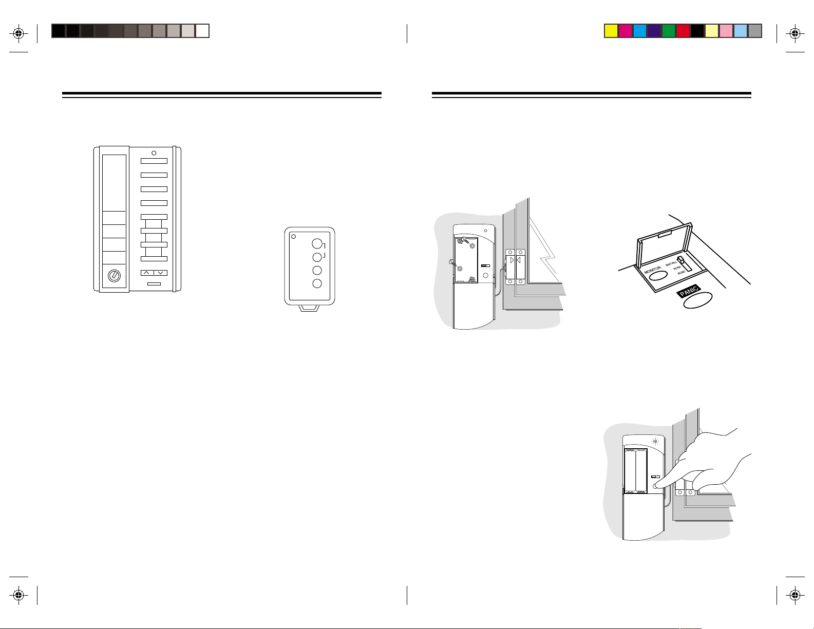
1. Install four AAA alkaline batteries in
the battery compartment (batteries
sold separately).
2. Set the INSTALL/RUN switch on the
console to INSTALL (located under
the flip up door).
3. Press ARM HOME or ARM AWAY
on the security/home automation
remote control. The Console emits
a tone.
4. Set the consoles slide switch back
to RUN1 or RUN2.
Note: If you do not hear a tone, press
the CODE button (located on the front
under the label) with a pencil, then
reinstall the remote as described above.
INSTANTDELAY
Key Chain Remote Control
1. Install two AAA alkaline batteries in
the battery compartment (batteries
sold separately).
2. Set the INSTALL/RUN switch on the
console to INSTALL (located under
the flip up door).
3. Press ARM on the key chain. The
Console emits a tone.
BATTERY
ARM
PANIC
DISARM
LIGHTS
ON
LIGHTS
OFF
4. Set the console's slide switch back
to RUN1 or RUN2.
5. To set up additional key chain
remote controls (up to eight), repeat
steps 1 and 2.
Note: If you do not hear a tone, remove
the batteries and then hold down the
ARM button for 3 seconds. Refit the
batteries and press ARM again. The
LED indicator will flash twice. You can
now install the key chain remote as
described above.
You can install any combination of
Remote Control types for a total of up
to sixteen Remote Controls. For
example, you can install eight key chain
remote controls and eight security/home
automation remote controls or any other
combination for a total of sixteen.
Installing Door/Window
Sensors
We recommend that you purchase
enough sensors to protect the front and
back door and any windows that are
obscured from view or easily accessible
(including basement windows).
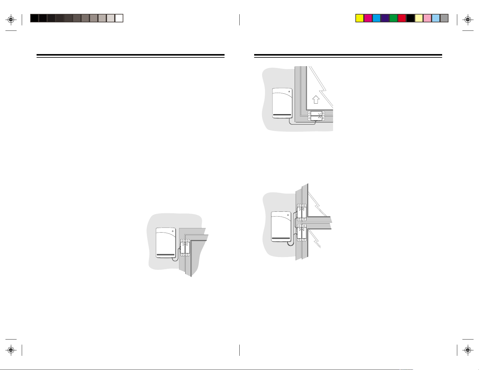
1. Mount the Door/Window Sensor and
the magnetic switch in the intended
location using the supplied screws
or double sided tape.
2. Install the magnet using the supplied
screws or double sided tape. The
arrows on the Door/Window Sensor
magnet and switch should be
aligned carefully so that they face
each other.
Note: The sensor and magnetic switch
supplied are already connected
together. If the wire is too long, you can
shorten it by cutting it to the length
required, stripping the ends and
reconnecting to the magnetic switch.
Initializing Door/Window
Sensors
This Procedure initializes the Door/
Window Sensors so that the Console
recognizes signals from the sensor.
1. Install two AA alkaline batteries in
the battery compartment (batteries
sold separately).
2. Set the INSTALL/RUN switch on the
console to INSTALL (located under
the flip up door).
3. Press TEST on the Door/Window
Sensor and hold for about a second.
Release the TEST button and the
LED blinks twice to confirm it has
been initialized.
–
+
DELAY
MAX MIN
+
–
TEST
98
Page 6
DOOR/WINDOW SENSOR
DOOR/WINDOW SENSOR
4. Press TEST again. The Console's
next unused zone indicator lights
and the Console beeps to indicate
it has accepted the sensor.
Note: If you do not hear a tone,
remove the batteries from the
sensor and then hold down the
TEST button for 3 seconds. Refit the
batteries and install the sensor again
as described above.
5. Set the switch on the front of the
Door/Window Sensor to MIN if you
are using it to protect a window or
MAX if you are using it to protect a
door.
6. Place one of the enclosed numbered
stickers on the sensor to show its
zone number.
To set up additional sensors (up to 16)
repeat steps 1-6.
If you mount the magnetic switches on
metal doors or metal door frames you
should ensure that they are no more
then 3/16" apart. On wooden surfaces
they can be up to 3/8" apart.
Testing Door/Window
Sensors
To test a Door/Window Sensor:
1. Set the INSTALL/RUN switch on the
console to RUN2 (located under the
flip-up door).
2. Open the door or window. The light
on the sensor blinks, the console
chimes and the zone light for the
sensor lights.
If the light on the sensor does not blink
and the console doesn't chime, check
that the Door/Window Sensor magnet
and switch are correctly aligned with the
arrows facing each other.
Typical Door/Window Sensor
mounting methods
For sliding windows, however, it is best
to mount the magnet and switch at the
bottom of the window with the arrows
facing each other. This way the magnets
will make a "clean break" from the switch
when the window is opened.
Note: You can use any standard N.C.
type magnet switches. N.C. means
Normally Closed. This type of magnetic
switch is supplied with the sensors.
These switches are normally closed
when the door or window is closed, and
open when the magnet is moved away.
This type of magnetic switch is used so
that if the wire between the switch and
the Door/Window Sensor is cut, the
alarm trips (tamper proof).
If you want to connect more than one
magnetic switch to a sensor you must
connect them in series (not in parallel).
You cannot use N.O. (Normally Open)
magnetic switches with this sensor.
Do not mount the magnet directly onto
a metal surface, use a wood or plastic
spacer.
DOOR/WINDOW SENSOR
The ideal location for the Door/Window
Sensor is high at the top of a window.
You can protect more than one door or
window from a single sensor by
installing additional magnetic switches.
Loop the switches in series from one
door or window to the next (using any
suitable wire).
1110
Page 7

6ft
Direction
of entry
Less sensitive
direction
MOTION DETECTOR
Correct Wrong
ge (ft)
SETTING UP MOTION SENSORS
Initializing Motion Sensors
MOTION DETECTOR
This procedure initializes each Motion
Sensor just like you initialize Door/
Window Sensors. Each Motion Sensor
will be assigned to one of the 16 zones.
1. Install four AA alkaline batteries in
the battery compartment on the
front of the Motion Sensor (batteries
sold separately).
Note: Place the Motion Sensor face
down so that it doesn't "see" anything
during installation. Otherwise if it is sees
motion it might be installed twice,
causing erroneous operation later.
2. Set the INSTALL/RUN switch on the
console to INSTALL (located under
the flip-up door).
3. Press the CODE button on the back
of the Motion Sensor with a pencil
to reset the code.
4. Press TEST on the back of the
Motion Sensor. The Console's next
unused zone indicator lights and the
Console sounds a tone to indicate
that the receiver accepted the
Motion Sensor.
LOW
SENSITIVITY
HIGH
TEST
CODE
5. Place one of the enclosed number
stickers on the Motion Sensor to
show the zone number.
6. To Set up additional Motion Sensors
(up to 16 zones) repeat steps 1-5.
Note: If you do not hear a tone, press
the CODE button again, then reinstall
the sensor as described above.
Installing Motion Sensors
Place the Motion Sensor on a
countertop or fix it to the wall using the
included mounting bracket.
The mounting bracket allows the Motion
Sensor to be swivelled up and down and
from left to right to obtain the desired
coverage.
The Motion Sensor should be placed at
a height of about 6 feet for best
coverage. Position the Motion Sensor
horizontally for maximum range.
For optimum performance the Motion
Sensor should be placed so that an
intruder walks across its path rather than
towards it.
The Motion Sensor can "see" up to a
distance of about 40 feet with a 90
degree field of view. It can be placed up
to about 100 feet away from the
Console.
Zone D
Zone C
Approx. 40ft
Mounting
Height (ft)
9
6
3
36912151821242730333639
Zone A Zone B Zone C Zone D
Zone B
Zone A
Ran
1312
Page 8

SETTING UP REMOTE MODULES
Lamp Module
A
I
EM
O
C
GK
•
•
•
•
•
•
•
•
1
9
513
15
3
711
•
•
•
•
•
•
•
UNIT
HOUSE
Remote Switch
1
9
513
A
I
EM
All types of Motion Sensors sense
motion by detecting a change in
temperature. Therefore, to help prevent
false alarms, do not place the Motion
Sensor near heating or air conditioning
vents.
Testing the Motion Sensor
The Motion Sensor includes a special
test mode which works as follows:
1. Set the sensitivity switch to 1.
2. Hold down the TEST button on the
back of the Motion Sensor until the
LED blinks twice.
3. Release the TEST button and wait
for about 20 seconds for the Motion
Sensor to settle.
4. Walk past the Motion Sensor. The
LED indicator lights as you move
and goes out if you keep very still,
or walk out of range of the detector.
If the range is low (less than 30 ft.) check
that the Motion Sensor is horizontal and
at a height of at least 5 ft. from the
ground.
The Motion Sensor will automatically
switch back to normal operation after
two minutes in test mode. If you want to
switch it back manually just press the
TEST button again.
To test the alarm
1. Arm the console and wait for about
45 seconds.
2. Walk in front of the Motion Sensor
and check that the alarm is
triggered.
After triggering the console, the Motion
Sensor automatically "locks out" for
around 45 seconds to save battery life.
Adjusting the Sensitivity of
Motion Sensors
Set the switch on the left of the Motion
Sensor (looking at the back) to 1 to trip
alarm if ANY movement is detected
(most sensitive).
Set the switch to 2 to trip the alarm only
if two successive movements are
detected or continuous movement is
detected in a short time (less sensitive
to pets).
Setting up Lamp Modules
When the alarm trips, lamps connected
to Lamp Modules set to A-13 (or other
codes on request from the monitoring
station - see page 18) flash on and off
for the duration of the alarm. After 4
minutes (or when you disarm the alarm)
the lamps stop flashing and remain on.
If you arm the system to give an exit
delay, Lamp Modules set to the same
House Code and Unit Code as the
console will turn on during the exit
countdown time. You can also control
Lamp Modules set to this code from the
LIGHT ON and LIGHT OFF buttons on
the remote controls, or from the
SECURITY LIGHT button on the Key
Chain Remote.
Choose a lamp you want to be a part of
the security system. Make sure the
lamp's on/off switch is on and plug the
lamp into the Lamp Module. Plug the
Lamp Module into any convenient AC
outlet. Set the House Code and Unit
Code dials on the Lamp Module to A13 (or other codes on request from the
monitoring station - see page 18).
Setting up Wall Switch
Modules
When the alarm trips, lights connected
to Wall Switch Modules (sold separately)
set to A-13 (or other codes on request
from the monitoring station - see page
18) flash on and off for the duration of
the alarm. After 4 minutes (or when you
disarm the alarm) the lights stop flashing
and remain on.
If you arm the system to provide an exit
delay, Wall Switch Modules set to the
same House Code and Unit Code as
the console will turn on during the exit
countdown time. You can also control
Wall Switch Modules set to this code
from the LIGHT ON and LIGHT OFF
buttons on the remote controls.
NOTE: Follow the installation
instructions included with the Wall
Switch Module, (sold separately). Set
the House Code and Unit Code to A-13
(or other codes on request from the
monitoring station - see page 18) if you
want the lamp to flash during an alarm.
1514
Page 9

Setting up the POWERHORN
1
•
•
15
3
•
513
•
•
711
•
•
9
UNIT
A
•
•
O
C
•
•
EM
•
•
GK
•
•
I
HOUSE
Power Horn
The POWERHORN Remote Powerline
Siren (sold separately) responds to
signals transmitted by the console (over
your house wiring).
When the alarm is tripped, the
POWERHORN is also tripped and
continues to sound until about 4
seconds after the alarm is reset or
disarmed.
1. Set House Code and Unit Code dials
on the POWERHORN to A-13
2. Plug the POWERHORN into a
standard AC outlet (not one
controlled by a wall switch).
NOTE: If you do not want to trigger the
POWERHORN when you turn on the
security light, you must request the
Monitoring Station to download the
information to re-configure your console
to generate an All Lights On/All Units
Off sequence. Then set the
POWERHORN codewheels to the
same House Code as your lamp
modules but to a different Unit Code.
™
WARNING: THE POWERHORN is
extremely loud! Do not stand near it
when you trip the alarm. Prolonged
exposure could cause permanent
hearing damage.
Using the POWERHORN with
other X10 controllers
In a panic situation, you can trip the
POWERHORN from other types of
Controllers as follows:
1. Press (and hold) the ON button
corresponding to the House and Unit
codes set on the POWERHORN.
After about 4 seconds the
POWERHORN trips. Press OFF to
turn it off.
2. Alternatively, repeatedly press All
Lights On followed by All Units Off.
Or repeatedly press the ON and
OFF buttons corresponding to the
POWERHORN's Unit Code. This will
trigger the POWERHORN after
about two ON-OFF sequences and
will continue as long as you keep
repeating the sequence. The siren
will shut off about 4 seconds after
the last key press.
SETTING UP FOR THE MONITORING STATION
Introduction to monitoring
The Monitor Plus™ Security System
incorporates the same digital
communicator technology found in
expensive high-end security products.
Features supported include account
number downloading and verification,
remote configuration and alarm type
confirmation.
When one of the sensors is activated
while the system is armed, a loud piercing
siren sounds. If the alarm is not disarmed
within the next few seconds using one of
the security coded remote controls, the
security system console automatically
dials the monitoring station and sends a
digitally coded message allowing the
station operator to identify your address,
telephone number and even the type of
alarm that occurred.
Automatic Lighting Control
When the Monitor Plus Security System
is armed in the away mode, an
automatic timer can be put into action
to turn lights, stereos, TVs, etc. on and
off at random times to make your home
look lived in.
Part of the information downloaded to
the console includes four unit codes for
X10 modules that can be used to give
your home a lived-in look. A code is
downloaded to give the location
(longitude and latitude) of your home,
which is then used to calculate the time
of dusk, and also a time is downloaded
to say when lights should all turn off.
Module Code 1 is turned on at dusk and
turns off at the set off-time (this is the
same code that flashes during an alarm
and can be controlled by the Keychain
and Security/Home Automation remotes).
This could be used for control of an
outside security light, for example.
The other 3 codes are for X10 modules
that turn on and off randomly between
dusk and the set OFF time. These could
be used for inside lights to give the
impression that your home is occupied.
The date and time is also downloaded
for daylight savings time.
Registering with the
Monitoring Station.
Once you have installed the Motion
Sensor, Door/Window Sensors and
Remote Controls you are ready to set
up for monitoring. To do this, all you need
to do is:
• Fill out the enclosed monitoring
agreement and mail or fax it to ORCA
Monitoring Services.
• Call ORCA Monitoring Services at
1-800-FOR-ORCA (1-800-367-6722)
and follow the instructions to have
your system initialized.
Note: Although you can register your
system as soon as it has been installed,
the Monitoring Station will not respond
to alarm calls until the signed monitoring
agreement has been received and you
have been allocated your security code
which will be notified to you by return.
1716
Page 10

USING THE SYSTEM
Calling Customer Service
After you have registered your system
you can easily call the customer service
center if you need help, or to change
any of the default options as follows:
• Set the Base Console slide switch to
RUN1 or RUN2.
• Press the MONITOR button. The
console automatically dials the
customer service number.
• Pick up the handset of a phone
connected to the same line as the
console.
Alternatively, you can dial the telephone
number in the usual way with any
telephone connected to the same line
as the console - just pick up the phone
and dial 1-800-FOR-ORCA.
(1-800-367-6722)
Options downloaded by the
service station
The options that are downloaded to your
security console when you register it are
listed below. You can change any of the
default options by calling the service
station (see above) and following the
instructions given to you.
1. 1st Monitoring Station Number:
The 1st number the console dials to
call the monitoring station.
2. 2nd Monitoring Station Number:
Backup phone number for the
monitoring station in case the first
number doesn't respond.
3. Service Station Number: Number
for the service station.
4. Account number: Your 8 digit
account number.
5. Exit delay: The amount of time the
console gives you to leave the house
when armed. (0-1000 seconds). The
default is 60 seconds.
6. Entry delay: The amount of time
you have to disarm the alarm when
you enter your home. (0-1000
seconds). The default is 30 seconds.
7. Delay before dialing: The amount
of time the console waits after it has
been triggered before calling the
monitoring station (to give you time
to disarm the system before it dials
in case of a false alarm). The default
is 40 seconds.
8. Test Dial Frequency: How many
days the console waits to call the
service station to check-in. Default
is 30 days.
9. House/Unit Code to flash lights:
(active only if the console is armed
in the away mode). The default
setting is code A-13.
10. House/Unit Codes for Lived-in
look: To control lights and
appliances to make your home look
lived in (active only if the console is
armed in the away mode). The
default settings are A-14, A-15, and
A-16.
11. Daylight parameters: Sets dusk
times for midwinter and midsummer
to activate lived-in look lighting
control (see option 10). Dusk times
for the rest of the year are calculated
automatically. Defaults are 4 PM in
midwinter and 10 PM in midsummer.
12. Preset off time: Time for the lights
to turn off after they have been
turned on automatically at dusk
(when armed in the away mode).
13. Daylight Savings Date: Date for
daylight savings time.
14. Panic Dialing ON/OFF: If this
option is set to ON, the console dials
out whenever PANIC is pressed. If
this option is set to OFF, the console
only dials out when PANIC is
pressed and the system is armed.
Default is ON.
15. Chirp ON/OFF: If chirp is ON, the
console chirps when it needs
programming. The default is OFF.
16. Siren ON/OFF: If the siren is set to
off, it will not be activated when the
alarm is triggered, although the
console still dials out. The default is
ON.
17. Flashing lights ON/OFF: If this
option is turned off, the lights will not
flash when the alarm is triggered,
although the console still dials out.
The default is ON.
18. Tone or Pulse: To change the dialer
to Touch Tone or Pulse dialing. The
default is Tone dialing.
Console Zone Indicators
The console displays the status of the
first eight zones. These indicators can
display four states, as follows:
Steady on: means that particular door
or window is open.
Steady off: means that particular door
or window is closed.
Slow Flashing: means that particular
Door/Window Sensor, or Motion Sensor
is reporting a problem. Low battery for
example.
Fast Flashing: means that particular
Door/Window Sensor or Motion Sensor
reported a problem and the fault was
bypassed, or a door or window is open
and has been bypassed.
Battery Light: Indicates the batteries
in the Console are low and need
replacing.
Monitor Light: Indicates the unit needs
to call the service station.
Armed Light: Indicates the unit is
armed and ready to activate.
1918
Page 11

Self checking system
All Door/Window Sensors and Motion
Sensors report in to the Console every
90 minutes. If the Console does not
receive a signal from the sensor within
four hours, it reports a problem with that
sensor by slowly flashing the
appropriate zone indicator. If you try to
arm the system with a zone indicator
flashing, the Console sounds a repetitive
trouble alarm. Either press DISARM,
correct the problem and press ARM
again, or press BYPASS while the
trouble alarm is sounding, then press
ARM. The zone(s) with a problem will
not be armed and the zone(s) indicators
will flash rapidly. All other zones will arm.
If you bypass an open window and arm
the system, and later close the window,
that zone will now be armed.
Arming and Disarming the
System
When you arm the system in the RUN1
or RUN2 mode, and open a door or
window the following happens:
• A loud (95dB) siren sounds for 4
minutes.
• Lights connected to Lamp Modules
and Wall Switch Modules (set to A-
13) flash on and off.
• The automatic dialer calls the
monitoring station to report the
problem (if you have signed up for
monitoring).
When armed RUN1 and RUN2 modes
are the same, opening a door or window
trips the alarm. When the system is in
the RUN2 mode and not armed, the
console sounds a pleasant chime when
you open a door or window. In RUN1
mode there are no chimes.
INSTANT Mode
Note: The Key Chain Remote Control
always arms the system in the
INSTANT mode.
1. If using the Security/Home
Automation remote, set its Delay
switch to MIN.
2. Press ARM. The Console emits a
tone and the ARMED indicator turns
on.
If you now open a door or window, the
alarm instantly trips, the siren sounds,
lights connected to Lamp Modules and
Wall Switch Modules (set to A-13) flash
on and off, and the dialer dials out a few
seconds later.
3. Press DISARM to stop the siren. The
lights remain on.
4. Press LIGHT OFF on the remote
control to turn off lights connected to
modules which you set to A-13.
DELAY Mode
(Security/Home Automation
Remote Only)
1. Set the DELAY switch on the
Security/Home Automation remote to
MAX.
2. Press ARM on the Remote Control.
Lamps connected to Modules set to
A-13 (or other codes on request from
the monitoring station - see page 18)
turn on. The console chimes for 1
minute while you leave the house.
Then you hear a beep signifying that
the system is armed, and the
lamps(s) turn off.
Open a door (that has its sensor set to
MAX), The console gives a pre-alarm
beep, and lamps connected to modules
set to the same House Code and Unit
Code as the Console turn on. After a
delay of approximately 30 seconds the
alarm sounds, Lamp and Wall Switch
Modules set to A-13 (or other codes on
request from the monitoring station - see
page 18) flash, and the automatic dialer
calls the monitoring station. The delay
can be changed by the service station.
3. Press DISARM to stop the siren. The
lights remain on.
ARM HOME/ARM AWAY
(Security/Home Automation
Remote only)
The Security/Home Automation remote
lets you arm the system with or without
Motion Sensors armed.
If you press ARM AWAY on the Remote
Control, all Door/Window Sensors AND
Motion Sensors will be armed.
If you press ARM HOME on the
Security/Home Automation remote,
ONLY Door/Window Sensors will be
armed. The Motion Sensors will NOT
be armed. This lets you arm the system
at night without accidentally tripping the
system yourself when you move around
the house.
The MIN/MAX switch on the Security/
Home Automation Remote lets you set
it to arm the system with or without an
exit/entry delay. When set to MIN
everything in the system will arm and
trip instantly. When set to MAX Motion
Sensors will still trigger the alarm
instantly, but Door/Window Sensors will
have a 1 minute exit and 30 sec. entry
delay (adjustable on request).
Arming Without the Remote
Control
You can arm the system without using
a Remote Control by pressing the ARM
button on the Console. Arming this way
ALWAYS arms the system in the Delay
mode.
2120
Page 12

TURNING LIGHTS ON AND OFF REMOTELY
9-16
1-8
ON
OFF
A
C
E
G
I
K
M
O
.
.
.
.
..
.
.
1
2
3
4
5
6
7
8
Sounding the PANIC Alarm
Triggering the panic alarm trips the
alarm but will not call the monitoring
station unless you arm the system first.
This option can be changed by the
service station. To trigger the panic
alarm:
• Press PANIC on the Security/Home
Automation Remote Control, or press
ARM and DISARM together on the
Keychain Remote. Press DISARM to
cancel the alarm.
Trouble Alarm
If you hear a repetitive trouble alarm
when you try to arm the system there
is a problem and the system does not
arm. You can:
• Correct the Problem - First press
DISARM to stop the trouble alarm.
Then correct the problem. Then arm
the system again.
• Ignore the problem - While the
trouble alarm is sounding, press
BYPASS. The indicator(s) for the
To See the Status of Zones
9-16
If there is a problem with zones 9-16,
you do not see a flashing zone light but
will hear a trouble alarm if you try to
arm the system. Press and hold
BYPASS. This bypasses the problem
and lets you see which zone is reporting
a problem. If you do not want to bypass
the problem, correct the problem then
arm the system.
After an Alarm
When you disarm the system after an
intrusion (or 4 minutes after the alarm
trips) the siren turns off and the lights
which were flashing remain on.
The ARMED indicator flashes and the
zone indicator for the violated zone is
on. Press ARM then DISARM on the
Remote Control to turn to off the zone
indicator and flashing ARMED indicator.
Press LIGHT OFF to turn off X10
Modules set to the same House Code
and Unit Code as the Console.
Keychain Remote Control
(KR10A)
BATTERY
ARM
PANIC
DISARM
LIGHTS
ON
LIGHTS
OFF
Press LIGHT ON or LIGHT OFF on the
Keychain Remote to turn on or off lights
connected to X10 Modules set to the
A-13 (or other codes on request from
the monitoring station - see page 18).
Note: This Button is not an ALL lights
on button.
Home Automation Remote
Control (HR12A)
problem zone(s) flash rapidly. Press
ARM to arm the system. The problem
zone(s) is/are not protected but all
other zones are.
Switching lights on/off from
the console
Press LIGHT ON or LIGHT OFF on the
console to turn on or off X10 Modules
set to A-13 (or other codes on request
from the monitoring station - see page
18).
The Home Automation Remote Control
provides independent control of up to
16 modules which you set to different
Unit Codes. It transmits signals to the
Security Console which retransmits the
signals to modules over your house
wiring. You can even dim and brighten
lights connected to Lamp and Wall
Switch Modules.
The Home Automation Remote does
not require any "installation." Just fit four
AAA alkaline batteries in its battery
compartment and set its House Code
dial to A (or other code on request from
the monitoring station - see page 18).
Note: If you already own a transceiver
module, you will no longer need to use it.
Security/Home Automation
Remote Control (SH624)
PANIC PANIC
ARM DISHOME ARM
ARM DISAWAY ARM
SECURITY
LIGHT
ON OFF
A
BRIGHT DIM
•
•
O
C
•
•
EM
•
•
ENTRY
GK
•
•
I
INSTANTDELAY
The Security/Home Automation Remote
Control combines the features of the
security remote with the features of the
Home Automation Remote. It lets you
arm and disarm the system in HOME
and AWAY modes (see page 21 for
details). It has SECURITY LIGHT ON
and OFF buttons which work like the
LIGHT ON and LIGHT OFF buttons on
the Keychain Remote. It also lets you
control up to four additional X10
Modules and dim and brighten lights too!
2322
Page 13

REPLACING BATTERIES
Security Remote Controls
For the Keychain Remote use two AAA
alkaline batteries.
For the Security/Home Automation
Remote use four AAA alkaline batteries.
After replacing batteries, the following
steps are necessary to determine that
the console still recognizes the remote
control.
1. Place the console slide switch under
the SETUP flip door to RUN2.
2. Press ARM on the Remote Control.
If the system arms, the Console
recognized the Remote Control and
no further action is necessary.
If the system did not arm:
1. Place the slide switch under the
SETUP flip door to INSTALL.
2. Press ARM on the Remote Control.
The Remote Control transmits a
random code to the console. The
Console acknowledges this with a
beep and logs in the Remote
Control. If you do not hear a beep
follow the instructions on page 8 to
re-initialize the remote.
Home Automation Remote
Control
The Home Automation Remote Control
uses four AAA alkaline batteries but it
does not require any installation. Just
set its House Code dial to match the
Console and it's ready to use.
Door/Window Sensors
If any of the Console's zone indicators
flash slowly, the Door/Window Sensor
or Motion Sensor (see next section) for
that zone has not reported in during the
last four hours. This is most likely caused
by dead batteries.
After replacing the batteries in the Door/
Window Sensor, the following steps are
necessary to determine that the
Console still recognizes it.
1. Place the console slide switch under
the SETUP flip door to RUN2.
2. Press TEST on the sensor. If the
Door/Window sensor LED flashes
and the console chimes, it
recognized the sensor and no
further action is necessary.
If you didn't hear a chime when you
pressed TEST:
1. Place the slide switch under the
SETUP flip door to INSTALL.
2. Press and hold TEST for 3 seconds
then release it. The Door/Window
Sensor LED flashes twice.
3. Press TEST again. The Door/
Window Sensor transmits a code to
the Console. The console
acknowledges this with a beep and
logs in the code.
The Door/Window Sensor will normally
be logged into the SAME zone number
as it was before you replaced the
batteries. However, if you replace the
battery in the sensor when its zone light
was NOT flashing, the sensor is logged
into the next sequential zone (instead
of the same zone it was in).
To avoid this, remove the old batteries
and wait at least 4 hours before installing
the new batteries.
Motion Sensors
If any if the Console's zone indicators
flash slowly, the Motion Sensor or Door/
Window Sensor (see previous section)
for that zone has not reported in during
the last four hours. This is most likely
caused by dead batteries.
After Replacing the batteries in the
Motion Sensor, the following steps are
necessary to determine that the
Console still recognizes it.
1. Place the slide switch under the
SETUP flip door to RUN1 or RUN2.
2. Press TEST on the Motion Sensor.
If the appropriate zone indicator
blinks, then the Console recognized
the Motion Sensor and no further
action is necessary.
If the zone indicator didn't blink
when you pressed TEST:
1. Place the slide switch under the
SETUP flip door to INSTALL.
2. Press TEST on the Motion Sensor.
The Motion Sensor transmits a code
to the Console. The console
acknowledges this with a beep and
logs in the Motion Sensor.
Console
The console’s backup battery allows the
system to work during a power outage.
The BATTERY LOW indicator on the
console lights when you need to replace
the backup batteries.
Installed sensors, and Central Station
phone numbers are stored in Electrically
Erasable Programmable Read Only
Memory (EEPROM) which will not lose
its data even if the power is out and the
battery is dead.
Four AA alkaline batteries provide at
least 12 hours of backup. Replace the
batteries at least once a year.
To remove all sensors and
remotes from the console's
memory:
• Set the console to INSTALL.
• Press PANIC, ARM HOME and ARM
AWAY at the same time.
Note: Telephone numbers and
configuration data downloaded by the
service center (such as entry and exit
delays etc.) cannot be erased, and can
only be changed on request by the
service center.
2524
Page 14

TROUBLESHOOTING
PROBLEM
If the system does not arm.
If a zone indicator flashes slowly. One of the sensors has not reported in,
If a zone indicator flashes rapidly.
• Check that the slide switch under the
SETUP flip door is set to RUN1 or
RUN2.
• Check that the red indicator on the
Remote Control turns on when you
press ARM. Replace the batteries
and reinstall the Remote if necessary.
in the last 4 hours.
Check that the batteries in the sensor
are good.
If you need to arm the system and want
to ignore a sensor which is not
functioning:
1. Press ARM on the Remote control.
You year a repetitive trouble alarm to
alert you that there is a problem.
2. While the trouble alarm is sounding,
press BYPASS on the Console. The
zone indicator flashes rapidly.
Then press ARM on the Remote
Control. The problem zone is not
protected but all other zones are armed.
Note: if you bypass an open window and
arm the system (as described above)
and later close the window, that zone
will now arm and its zone light will stop
flashing.
You pressed the BYPASS button to arm
the system while a sensor was reporting
a problem.
SOLUTION
If you hear a repetitive trouble alarm
when you try to arm the system, and it
does not arm.
If the alarm trips when you enter the
house before you have time to disarm
it.
Lights will not turn on or off from the
LIGHT ON or LIGHT OFF buttons on
the Remote Control.
SOLUTIONPROBLEM
Check the zone indicators. If a door or
window is open, its zone indicator is on.
If there is a problem with a Door/Window
Sensor or Motion Sensor, its zone
indicator flashes slowly. Either:
• Press DISARM. Check each Door/
Window Sensor is working properly
and that no doors or windows are
open. Then arm the system. Or:
• While the trouble alarm is sounding,
press BYPASS to override the
problem zone (its zone indicator then
flashes rapidly). Then arm the
system.
Arm the system in the delay mode.
To do this: Set the MIN/MAX switch on
the entrance Door/Window Sensor to
MAX and the Remote Control to MAX
(Security/Home Automation Remote)
and then press ARM.
• Be sure you set House and Unit
codes on the module(s) to the same
letter and number as downloaded to
the Console (default is A-13).
• Be sure the light you are trying to
control has its on/off switch in the on
position. Be sure its bulb is good.
• Plug the module into another outlet
near the Console.
• Check that the battery indicator on
the Remote Control comes on when
you press a button. Replace batteries
and reinstall remote if necessary.
2726
Page 15

SOLUTIONPROBLEM
PROBLEM
SOLUTION
You open a door or window and the
alarm does not trip.
If appliances turn off during an alarm.
If you do not hear a beep from the
Console when you press ARM to install
a Remote Control.
• Check that the system is armed.
• Be sure the slide switch under the
SETUP flip door is in the RUN1 or
RUN2 position.
• Check to see if the alarm trips when
you press TEST on the Door/Window
Sensor.
• If the alarm does not trip when you
press TEST, check that the indicator
on the sensor comes on when you
press TEST.
If the indicator does not come on,
replace the batteries and reinstall the
sensor if necessary.
The system flashes lights by repetitively
transmitting A-13 on/off. Therefore any
appliances (connected to Appliance
Modules set to A-13) which were on at
the time of the alarm will turn off.
If you do not want this to happen, set
the Appliance Module(s) to a different
Housecode from the one you set on the
Console.
Check to see if you can arm the system
when the Console is in the RUN mode.
If you can, the Remote Control is
already installed and no further action
is necessary. If not:
1. Check that the console is set to the
INSTALL mode.
If you do not hear a beep from the
Console when you press TEST to install
a Door/Window Sensor or Motion
Sensor.
If the battery indicator on the Console
is on.
If you lose your remote control.
If the system Arms or Disarms by itself
If the red light on the Remote Control
stays on during installation.
With the Console in the RUN 2 mode,
check that it chimes when you press
TEST on the Door/Window Sensor, or
the zone indicator for a Motion Sensor
blinks. If it does, then sensor is already
installed and no further action is
necessary. If not:
1. Check that the Console is set to the
INSTALL mode.
2. Change the code on the sensor (see
Setting Up Door/Window Sensors and
Setting Up Motion Sensors.
Replace the console's batteries. Four
AA alkaline batteries provide
approximately 12 hours of backup.
Replace batteries at least once a year.
Reinstall your complete system to
prevent someone else from using the
lost remote control.
A neighbor might have a compatible
system. Reinstall the complete system
so that it chooses different RF codes.
Press CODE then press ARM. If it still
stays on, remove the batteries, wait a
few seconds, then replace the batteries.
Press CODE then press ARM again.
2. Re-initialize the remote (see page 8
- Setting Up Remote Controls).
2928
Page 16

PROBLEM SOLUTION
If the armed indicator is flashing. This indicates that there has been an
intrusion. Also, if a zone indicator is on,
this indicates which zone was violated.
To turn the zone indicator off, and stop
the armed indicator from flashing, press
the LIGHT ON or LIGHT OFF button
on the remote control. If a zone indicator
is not on, the violated zone will have
been one of the second eight zones.
Press BYPASS to see which zone was
tripped.
If the POWERHORN does not trip when
the alarm trips.
• Be sure you set the Housecode on
the POWERHORN to the same letter
and number as downloaded to the
Console.
• Plug the POWERHORN into another
outlet near the Console.
Special Notes
Intercom Systems
Intercom systems which send voice
signals over existing electrical wiring
might interfere with the ability to control
modules from your Monitor Plus security
system with the intercom in use. If the
intercom system has its own separate
wiring it will not cause a problem.
Arming
The ARM button on the Console arms
the system in the delay mode only. Use
a Remote Control if you want to arm
the system in the instant (MIN) mode.
Outdoor Infrared Motion Sensor
The Outdoor Motion Sensor (Model
PR511) will not trigger the Monitor Plus
security system. It can, however, control
the same lights that the security system
controls.
The Motion Sensor causes false alarms.
The MONITOR light is flashing.
• All brands of Motion Sensors sense
motion by detecting a change in
temperature, therefore do not place
the sensor near any sources of heat
such as over an air conditioner or
heating vent.
• Do not place in a direct source of
bright light, such as sunlight.
• Do not place near cellular phones or
microwave ovens.
This means that you need to call the
service station at 1-800-FOR-ORCA,
(1-800-367-6722) for setup of the
console.
3130
Page 17

ONE YEAR LIMITED WARRANTY
X10.COM A DIV. OF X10 WIRELESS TECHNOLOGY, INC. (X10) WARRANTS ITS
PRODUCTS TO BE FREE FROM DEFECTIVE MATERIAL AND WORKMANSHIP FOR A
PERIOD OF ONE (1) YEAR FROM THE ORIGINAL DATE OF PURCHASE AT RETAIL.
X10 AGREES TO REPAIR OR REPLACE, AT ITS SOLE DISCRETION, A DEFECTIVE
X10 PRODUCT IF RETURNED TO X10 WITHIN THE WARRANTY PERIOD AND WITH
PROOF OF PURCHASE.
IF SERVICE IS REQUIRED UNDER THIS WARRANTY:
1. CALL 1-800-675-3044, OR VISIT WWW.X10.COM, OR E-MAIL SALES@X10.COM
TO OBTAIN A RETURN MERCHANDISE AUTHORIZATION (RMA) NUMBER.
2. RETURN THE DEFECTIVE UNIT POSTAGE PREPAID TO THE ADDRESS BELOW.
3. ENCLOSE A CHECK FOR $4.00 TO COVER HANDLING AND RETURN POSTAGE.
4. ENCLOSE A DATED PROOF OF PURCHASE.
5. X10 IS NOT RESPONSIBLE FOR SHIPPING DAMAGE. UNITS TO BE RETURNED
SHOULD BE PACKED CAREFULLY.
THIS WARRANTY DOES NOT EXTEND TO ANY X10 PRODUCTS WHICH HAVE BEEN
SUBJECT TO MISUSE, NEGLECT, ACCIDENT, INCORRECT WIRING OR TO USE IN
VIOLATION OF OPERATING INSTRUCTIONS FURNISHED BY US, NOR EXTEND TO
ANY UNITS ALTERED OR REPAIRED FOR WARRANTY DEFECT BY ANYONE OTHER
THAN X10. THIS WARRANTY DOES NOT COVER ANY INCIDENTAL OR
CONSEQUENTIAL DAMAGES AND IS IN LIEU OF ALL OTHER WARRANTIES
EXPRESSED OR IMPLIED AND NO REPRESENTATIVE OR PERSON IS AUTHORIZED
TO ASSUME FOR US ANY OTHER LIABILITY IN CONNECTION WITH THE SALE OF
OUR PRODUCTS.
SOME STATES DO NOT ALLOW LIMITATIONS ON HOW LONG AN IMPLIED
WARRANTY LASTS, AND/OR THE EXCLUSION OR LIMITATION OF INCIDENTAL OR
CONSEQUENTIAL DAMAGES SO THE ABOVE LIMITATIONS AND EXCLUSIONS MAY
NOT APPLY TO THE ORIGINAL CUSTOMER. THIS WARRANTY GIVES YOU SPECIFIC
RIGHTS AND YOU MAY ALSO HAVE OTHER RIGHTS WHICH VARY FROM STATE TO
STATE.
X10.com, a div. of X10 Wireless Technology, Inc.
Returns Depot, 3824 North 5th St.,
Suite C, North Las Vegas, NV 89032
www.x10.com/support
DC8700P-OM-7/02
 Loading...