

Page 1
HH
OMEOME
OME
H
OMEOME
HH
CK11ACK11A
CK11A
CK11ACK11A
AA
CTIVECTIVE
A
CTIVE
CTIVECTIVE
AA
A A
UTOMAUTOMA
UTOMA
A
UTOMAUTOMA
A A
HH
H
HH
TIONTION
TION
TIONTION
OMEOME
OME
OMEOME
S S
S
S S
YSTEMYSTEM
YSTEM
YSTEMYSTEM
OO
O
OO
WNERWNER
WNER
WNERWNER
’’
’
’’
M M
SS
M
S
SS
M M
ANUALANUAL
ANUAL
ANUALANUAL
Page 2
R R
T T
F F
EADEAD
EAD
EADEAD
T
T T
HISHIS
HIS
HISHIS
22
2
22
R
R R
SS
C C
AFETYAFETY
ONSIDERAONSIDERA
ONSIDERA
ONSIDERAONSIDERA
TIONSTIONS
TIONS
TIONSTIONS
AFETY
S
C
AFETYAFETY
SS
C C
Remember to exercise good common sense when using your ActiveHome home
automation system - especially when scheduling unattended devices. There can be
some unexpected consequences if not used with care. For example, an empty coffee
pot can be remotely turned on. If that should happen, your coffee pot could be
damaged from overheating. If an electric heater is turned on by remote control while
clothing is draped over it, a fire could result. DO NOT USE the system for the control of
high power heating appliances such as portable heaters.
Caution: To reduce the risk of electric shock, do not disassemble any part of the Home
Automation System. No user-serviceable parts are inside. If you spill liquid on a unit,
disconnect the unit from the AC outlet to prevent possible fire or shock hazard and consult
authorized service personnel.
Powerline operated equipment or accessories connected to any of these units should bear
the UL listing or CSA certification mark and should not have been modified in any way that
might defeat their safety features.
Warning: T o prevent electric shock hazard, do not expose any part of the Home
Automation System to rain or moisture.
F
F F
IRSTIRST
IRST
IRSTIRST
! !
!
! !
~ R~ R
T T
F F
T
T T
! ~! ~
HISHIS
IRSTIRST
HIS
IRST
F
! ~
HISHIS
IRSTIRST
F F
! ~! ~
33
3
33
EADEAD
EAD
~ R
EADEAD
~ R~ R
FCC CFCC C
AUTIONAUTION
AUTION
FCC C
AUTIONAUTION
FCC CFCC C
THIS DEVICE COMPLIES WITH PART 15 OF THE FCC RULES.
OPERATION IS SUBJECT TO THE FOLLOWING TWO CONDITIONS:
(1) THIS DEVICE MAY NOT CAUSE HARMFUL INTERFERENCE, AND
(2) THIS DEVICE MUST ACCEPT ANY INTERFERENCE RECEIVED, INCLUDING INTERFERENCE THAT
MAY CAUSE UNDESIRED OPERATION.
This equipment generates and uses radio frequency energy, and if not installed and used properly, that
is, in strict accordance with the manufacturers instructions, it may cause interference to radio and
television reception. It has been type tested and found to comply with the limits for remote control
devices in accordance with the specifications in Sub-Parts B and C of Part 15 of FCC Rules, which are
designed to provide reasonable protection against such interference in a residential installation.
However, there is no guarantee that interference will not occur in a particular installation. If this
equipment does cause interference to radio or television reception, which can be determined by
unplugging the equipment, try to correct the interference by one or more of the following measures.
• Reorient the antenna of the radio/TV experiencing the interference.
• Relocate the interface with respect to the radio/TV.
• Move the interface away from the radio/TV.
• Plug the interface into an outlet on a different electrical circuit from the radio/TV
experiencing the interference.
• If necessary, consult your local Dealer for additional suggestions.
NOTE: Modifications to any of the components in this kit will void the user’s authority to operate this
equipment.
Page 3
C C
ONTENTSONTENTS
C
ONTENTS
ONTENTSONTENTS
C C
II
NTRODUCTIONNTRODUCTION
NTRODUCTION
I
NTRODUCTIONNTRODUCTION
II
GG
G
GG
II
NSTNST
NST
I
NSTNST
II
SS
ETTINGETTING
S
ETTING
ETTINGETTING
SS
..........................................................................................................................................................................................................
.....................................................................................................
..........................................................................................................................................................................................................
S S
ETTINGETTING
ETTING
ETTINGETTING
ONTROLLERS AND MODULES .................................................................................... 8
C
OUSE CODES AND UNIT CODES ............................................................................ 10
H
ALLINGALLING
ALLING
ALLINGALLING
RANSCEIVER MODULE ........................................................................................... 1 1
T
AMP MODULE .................................................................................................... 12
L
KEYCHAIN REMOTE ............................................................................................... 1 3
IN-1 SUPERREMOTE ............................................................................................ 14
6-
OMPUTER INTERFACE ............................................................................................ 1 5
C
UTTON DESCRIPTIONS .......................................................................................... 16
B
ETTING UP FOR TV, VCR, CABLE BOX AND SATELLITE RECEIVER ....................................... 18
S
USING AUX TO CONTROL A SECOND TV, VCR, C ABLE BOX OR SATELLITE RECEIVER .............. 20
EARCHING FOR CODES ........................................................................................ 22
S
IDENTIFYING CODES FOUND USING THE SEARCH PROCEDURE ............................................. 23
..................................................................................................................................................................................................
TT
ARAR
TEDTED
T
AR
TED
S
.................................................................................................
TT
ARAR
TEDTED
S S
..................................................................................................................................................................................................
C C
THETHE
THE
C
THETHE
C C
U U
PP
YOURYOUR
P
YOUR
U
PP
YOURYOUR
U U
OMPONENTSOMPONENTS
OMPONENTS
OMPONENTSOMPONENTS
S S
RR
UPERUPER
UPER
S
R
UPERUPER
S S
RR
............................................................................................................................................................
..............................................................................
............................................................................................................................................................
....................................................................................................................................................
EMOTEEMOTE
EMOTE
..........................................................................
EMOTEEMOTE
....................................................................................................................................................
ONTENTSONTENTS
ONTENTS
ONTENTSONTENTS
~ ~
~
~ ~
~ C~ C
~ C
~ C~ C
SETTING THE SLEEP TIMER ....................................................................................... 24
66
6
66
ONTROLLING X10 MODULES................................................................................. 25
C
88
8
88
TO SET THE X10 SLEEP TIMER .................................................................................. 26
HANGING THE X10 HOUSE CODE: ........................................................................ 27
C
ONTROLLING AN IR MINI CONTROLLER..................................................................... 28
C
1111
11
1111
AA
HH
S S
CTIVECTIVE
OMEOME
A
CTIVE
OME
H
CTIVECTIVE
OMEOME
AA
HH
NSTALLING ACTIVEHOME SOFTWARE.......................................................................... 30
I
SING ACTIVEHOME TO CONTROL MODULES............................................................... 31
U
SCHEDULES AND MACROS ...................................................................................... 33
THER INFORMATION ............................................................................................ 41
O
SAMPLE FILE ........................................................................................................ 42
1616
16
1616
RGANIZING THE ACTIVEHOME DESKTOP ................................................................... 42
O
ELP AT YOUR FINGERTIPS ....................................................................................... 43
H
CONFIGURING THE SERIAL POR T ............................................................................... 4 3
EE
XPXP
ANDINGANDING
XP
ANDING
E
XPXP
ANDINGANDING
EE
TT
ROUBLESHOOTINGROUBLESHOOTING
ROUBLESHOOTING
T
ROUBLESHOOTINGROUBLESHOOTING
TT
WW
ARRANTYARRANTY
ARRANTY
W
ARRANTYARRANTY
WW
............................................................................................................................................................................
OFTWOFTW
AREARE
OFTW
ARE
S
......................................................................................
OFTWOFTW
AREARE
S S
............................................................................................................................................................................
S S
YOURYOUR
YOUR
YOURYOUR
..............................................................................................................................................................................................................
.......................................................................................................
..............................................................................................................................................................................................................
..................................................................................................................................................................
YSTEMYSTEM
YSTEM
S
.................................................................................
YSTEMYSTEM
S S
..................................................................................................................................................................
..........................................................................................................................................................................................
.............................................................................................
..........................................................................................................................................................................................
2929
29
2929
4444
44
4444
4646
46
4646
4747
47
4747
44
4
44
55
5
55
Page 4

I I
NTRODUCTIONNTRODUCTION
I
NTRODUCTION
NTRODUCTIONNTRODUCTION
Congratulations on your purchase of the ActiveHome PC based home automation system!
Make your lights and appliances go to work for you...
ActiveHome brings added security, convenience and energy savings to your home by
managing your lights and appliances with personalized Macros defined by you.
ActiveHome’s easy-to-use software and hardware can automate almost any light or
appliance in your home. And it’s easy to install. Within minutes, ActiveHome can make your
lights and appliances go to work for you!
Here are just some of the things you can do with your ActiveHome Home Automation
System...
• Make your house look “lived-in” by having certain lights or appliances “learn” your
normal living pattern
• Program your lights to come on at dusk (not at a preset time) — so you don’t have to
come home to a dark house.
• Control individual (or groups) of lights or appliances by remote control from any room
in the home.
• Create personalized groups of commands (“Macros”) for certain times of the day, like
when you wake-up or go to bed.
I I
~ I~ I
NTRODUCTIONNTRODUCTION
~ I
NTRODUCTION
NTRODUCTIONNTRODUCTION
~ I~ I
Use this manual to become familiar with ActiveHome...
This manual will briefly explain how your ActiveHome system works and how to set it up.
Next, it will teach you how to control a simple lamp from your PC. Finally, once you’ve
mastered the basics, the manual will show you different automation Macros you can setup
using your ActiveHome software.
~ ~
~
~ ~
66
6
66
77
7
77
Page 5
G G
G
ANDAND
AND
ANDAND
G G
M M
M
M M
Because we know that you are eager to get started, we’ve kept this introduction as short
as possible, but it contains very valuable information, so you should read through it very
carefully.
CC
ONTROLLERSONTROLLERS
ONTROLLERS
C
ONTROLLERSONTROLLERS
CC
The first thing you need to understand is that there are two different devices you need to
control your house; Controllers and Modules. Any light or appliance that you want to
control is plugged into a Module and that Module is then plugged into a standard AC
outlet.
Modules receive commands from Controllers. Examples include the Lamp Module that
came with this kit. The Transceiver Module also in this kit is another example (although it
also doubles as a controller as described later).
Controllers are also plugged into standard wall outlets and send commands to Modules
over your existing electrical wiring in your house without affecting your electricity in any
way.
The Transceiver Module that came with this kit works as a controller when it is used with a
remote control such as the ones included with this kit. When the Transceiver Module
receives a command from a remote it sends digital signals over your existing house wiring
to a Module which receives the signals and executes the command.
ETTINGETTING
ETTING
ETTINGETTING
ODULESODULES
ODULES
ODULESODULES
S S
S
S S
88
8
88
TT
ARAR
TEDTED
T
AR
TED
TT
ARAR
TEDTED
~ G~ G
S S
ETTINGETTING
~ G
ETTING
ETTINGETTING
~ G~ G
The remotes use radio frequency (RF) signals to send commands to the Transceiver
module. RF signals can go right through walls, so you can use the remotes to control
lights or appliances from anywhere in the home.
With your ActiveHome Home Automation Interface and software, your PC becomes a
very intelligent Controller for all of your home automation tasks.
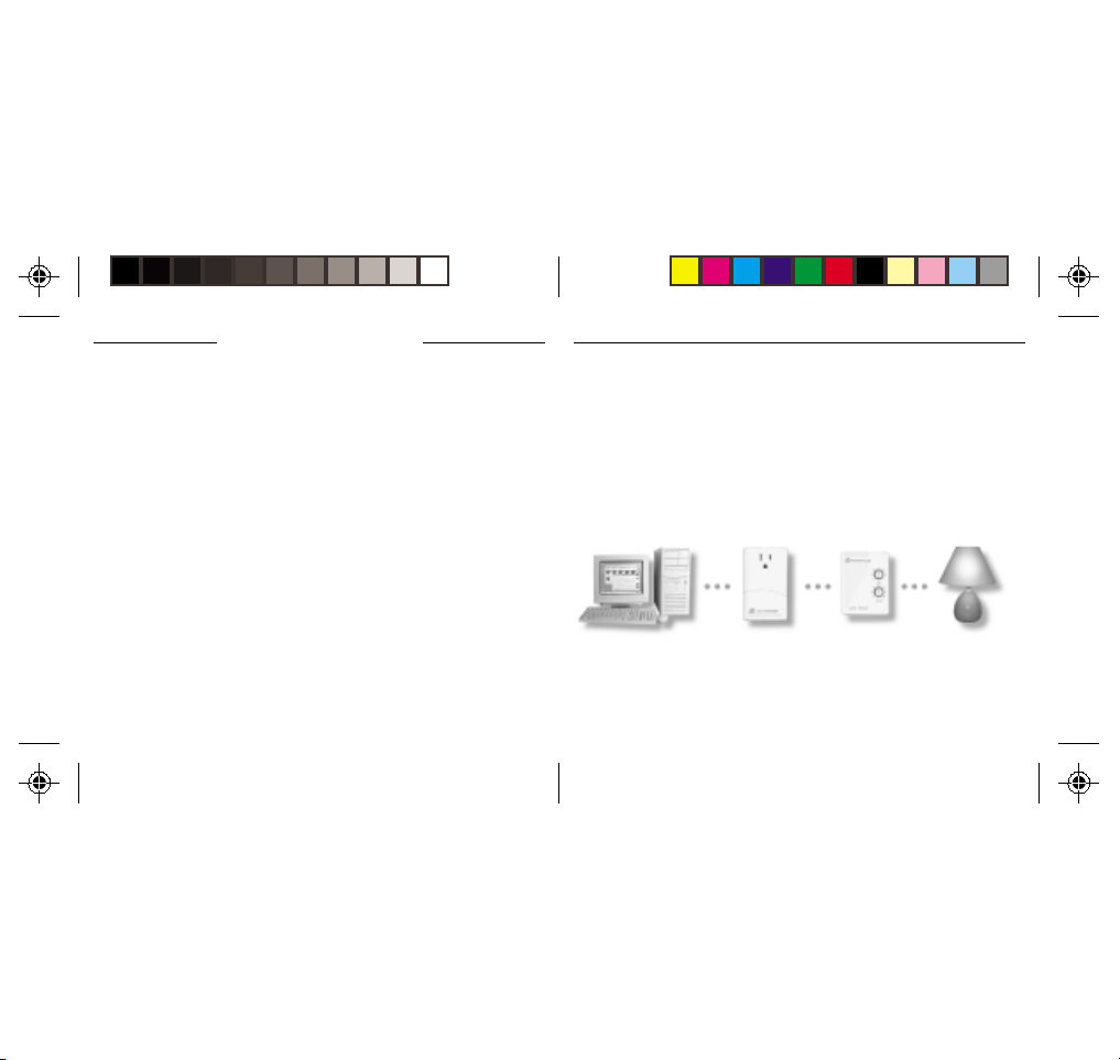
The ActiveHome Interface connects to your computer’s serial port and then plugs into a
wall outlet. The ActiveHome software tells the Interface what to do. The Interface then
sends digital signals over your existing house wiring to a Module which receives the
signals and executes the command sent by the PC.
~ ~
TT
ARAR
TEDTED
T
AR
TED
S
~
TT
ARAR
TEDTED
S S
~ ~
99
9
99
Page 6
~ G~ G
S S
ETTINGETTING
~ G
ETTING
ETTINGETTING
~ G~ G
HH
C C
U U
OUSEOUSE
ODESODES
C
C C
ODES
ODESODES
ANDAND
AND
ANDAND
OUSE
H
OUSEOUSE
HH
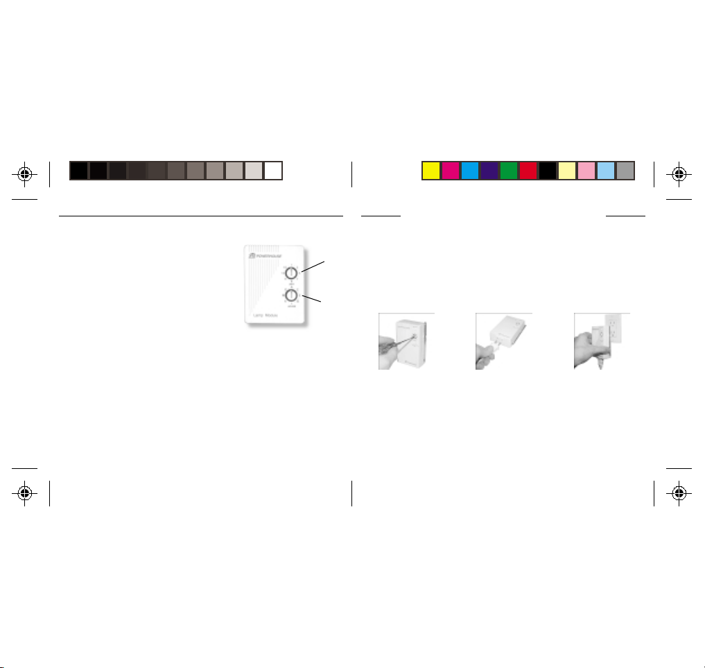
Each Module has a specific address made up of a
House Code (red dial on the face of the Module) and
a Unit Code (black dial on the face of the Module).
The Controller first sends an address and then a
command on the AC power lines. Only the Module
with a matching address will execute the command. If
more than one Module has the same address, both
Modules will execute the command.
Addresses are set on the Module by turning the two
dials on the front of the Module to the desired letter and number (using a small
screwdriver or a coin). The House Code is selected from the letters A through P, and the
Unit Code is selected from the numbers 1 through 16.
U
U U
NITNIT
NIT
NITNIT
C C
C
C C
ODESODES
ODES
ODESODES
~ ~
TT
ARAR
TEDTED
T
AR
TED
S
~
TT
ARAR
TEDTED
S S
~ ~
UNIT CODE
DIAL
HOUSE CODE
DIAL
1010
10
1010
I I
NSTNST
I
NST
NSTNST
I I
TT
RANSCEIVERRANSCEIVER
RANSCEIVER
T
RANSCEIVERRANSCEIVER
TT
The T ransceiver Module receives radio frequency (RF) commands from remotes to operate
a lamp or appliance plugged into it. The T ransceiver Module also passes on commands
over your house wiring to control other X10 modules. Note that unlike the Lamp Module
you cannot dim and brighten a lamp connected to the Transceiver Module.
You should locate the Transceiver Module centrally in the home for maximum range when
controlled by a remote.
1.1.
1. Set the House Code to ‘A’
1.1.
and the Unit Code slide
switch to 1.
Note:
when controlled from a remote or a controller such as the Computer Interface. Set to Unit
Code 1, or Unit Code 9.
M M
ODULEODULE
ODULE
M
ODULEODULE
M M
The slide switch sets the Unit Code for the Transceiver Module’s built -in receptacle
ALLINGALLING
ALLING
ALLINGALLING
2.2.
2. Plug a lamp or appliance
2.2.
into the Transceiver
Module.
THETHE
THE
THETHE
C C
OMPONENTSOMPONENTS
C
OMPONENTS
OMPONENTSOMPONENTS
C C
1111
11
1111
3.3.
3. Plug the Transceiver
3.3.
Module into a convenient
AC outlet. Fully extend
the antenna.
Page 7
~ I~ I
~ I
~ I~ I
ALLINGALLING
ALLING
ALLINGALLING
C C
THETHE
THE
C
THETHE
C C
NSTNST
NST
NSTNST
OMPONENTSOMPONENTS
OMPONENTS
OMPONENTSOMPONENTS
~ ~
~
~ ~
~ I~ I
~ I
~ I~ I
ALLINGALLING
ALLING
ALLINGALLING
C C
THETHE
THE
C
THETHE
C C
NSTNST
NST
NSTNST
OMPONENTSOMPONENTS
OMPONENTS
OMPONENTSOMPONENTS
~ ~
~
~ ~
LL
M M
AMPAMP
ODULEODULE
AMP
ODULE
L
M
AMPAMP
ODULEODULE
LL
M M
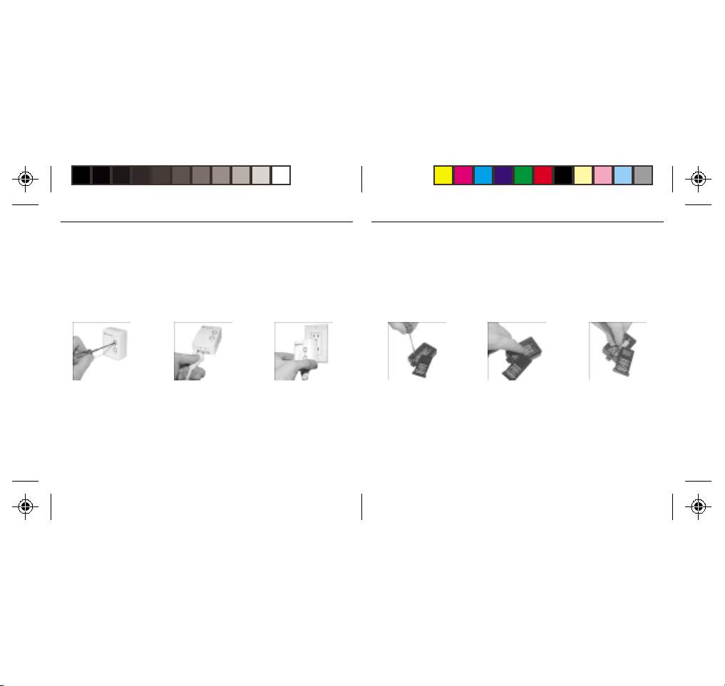
The Lamp Module may be used to control any incandescent lamp rated up to 300W. It is
not suitable for other types of lamp such as fluorescent or energy saving lamps, or lamps
which include a dimmer control.
Caution: Do not connect an appliance such as a coffee pot or heater to the Lamp
Module. It may damage the module and the appliance and could cause a fire hazard.
1.1.
1. Set the House Code to ‘A’
1.1.
and the Unit Code to ‘2’.
2.2.
2. Plug a lamp into the
2.2.
Lamp Module.
1212
12
1212
3.3.
3. Plug the Lamp Module
3.3.
into a convenient AC
outlet.
KK
K
KK
Use the Keychain R emote to control the Transceiver Module to turn lights on and off. You
can control up to two lights and appliances. The Keychain Remote is very convenient for
switching on entrance lights from your car when you return home in the evening.
After setting up the Keychain Remote as described below, you will be able to use the left
key to control the Transceiver Module and the right key to control the Lamp Module.
1.1.
1. Slide off the batter y cover
1.1.
R R
EYCHAINEYCHAIN
EYCHAIN
R
EYCHAINEYCHAIN
R R
and use a small
screwdriver to set the
code wheel to ‘A’.
EMOTEEMOTE
EMOTE
EMOTEEMOTE
2.2.
2. Move the slide switch to
2.2.
position 1-2.
1313
13
1313
3.3.
3. Install two AAA batteries
3.3.
and refit the battery
cover.
Page 8

ALLINGALLING
ALLING
ALLINGALLING
C C
THETHE
THE
C
THETHE
C C
~ I~ I
NSTNST
NST
~ I
NSTNST
~ I~ I
OMPONENTSOMPONENTS
OMPONENTS
OMPONENTSOMPONENTS
~ ~
~
~ ~
~ I~ I
~ I
~ I~ I
ALLINGALLING
ALLING
ALLINGALLING
C C
THETHE
THE
C
THETHE
C C
NSTNST
NST
NSTNST
OMPONENTSOMPONENTS
OMPONENTS
OMPONENTSOMPONENTS
~ ~
~
~ ~
6-6-
-1 S-1 S
ININ
IN
6-
-1 S
ININ
6-6-
-1 S-1 S
The 6-in-1 SuperRemote allows you to control practically everything electrical in your
home. It combines IR technology that lets you control all your TV, VCR, Cable and
Satellite equipment with X10 RF technology that lets you control lamps and appliances
anywhere in your home.
T o find out more about configuring the SuperRemote to work with your audio/video
equipment, see the section titled “Setting Up your SuperRemote.”
1.1.
1. Push the tab and lift off
1.1.
the battery cover.
UPERUPER
UPER
UPERUPER
RR
EMOTEEMOTE
EMOTE
R
EMOTEEMOTE
RR
2.2.
2. Fit two AAA batteries,
2.2.
taking care to match the
+ and - marks in the
battery compartment.
1414
14
1414
CC
C
CC
The Computer Interface connects to the serial port of your PC. When you run the
ActiveHome software, timer events, macros and other functions are downloaded to the
interface through the serial cable.
Batteries in the interface keep its clock running if the power fails, so when the power is
restored any timed events are resumed automatically.
OMPUTEROMPUTER
OMPUTER
OMPUTEROMPUTER
I I
I
I I
NTERFNTERF
NTERF
NTERFNTERF
ACEACE
ACE
ACEACE
Install the interface as follows:
1.1.
1. Connect one end of the
1.1.
interface cable to your
computer.
2.2.
2. Plug the other end of the
2.2.
cable into the Computer
Interface.
3.3.
3. Plug the Computer
3.3.
Interface into a
convenient AC outlet
Continued...
1515
15
1515
Page 9

~ I~ I
~ I
~ I~ I
ALLINGALLING
ALLING
ALLINGALLING
C C
THETHE
THE
C
THETHE
C C
NSTNST
NST
NSTNST
OMPONENTSOMPONENTS
OMPONENTS
OMPONENTSOMPONENTS
~ ~
~
~ ~
4.4.
4. Plug your computer into
4.4.
the Computer Interface
(optional).
S S
ETTINGETTING
S
ETTING
ETTINGETTING
S S
BB
D D
UTTONUTTON
ESCRIPTIONSESCRIPTIONS
UTTON
UTTONUTTON
ESCRIPTIONS
D
ESCRIPTIONSESCRIPTIONS
D D
TOR LIGHTTOR LIGHT
TOR LIGHT
TOR LIGHTTOR LIGHT
B
BB
INDICAINDICA
INDICA
INDICAINDICA
The indicator light flashes
when the remote is
operating.
POWERPOWER
POWER
POWERPOWER
Works in the same way as
your original remote.
5.5.
5. Slide off the batter y cover
5.5.
and fit 2 AAA batteries in
the battery compartment.
U U
PP
YOURYOUR
U
P
YOUR
PP
YOURYOUR
U U
SET UPSET UP
SET UP
SET UPSET UP
Used for programming the
remote.
X10X10
X10
X10X10
Lets you control X10
modules to operate lamps
and appliances around
your home.
1616
16
1616
S S
S
S S
UPERUPER
UPER
UPERUPER
RR
R
RR
TVTV
, VCR, CBL, AUX1,, VCR, CBL, AUX1,
TV
, VCR, CBL, AUX1,
TVTV
, VCR, CBL, AUX1,, VCR, CBL, AUX1,
AUX2, SAAUX2, SA
AUX2, SA
AUX2, SAAUX2, SA
Used to select the device to
control. SAT includes DSS.
0-90-9
0-9
0-90-9
Used as your original
remote and to enter device
codes.
EMOTEEMOTE
EMOTE
EMOTEEMOTE
TT
T
TT
LASTLAST
LAST
LASTLAST
Selects the last channel
viewed on your TV, VCR,
Cable Box or Satellite
Receiver.
CHANNEL +/-CHANNEL +/-
CHANNEL +/-
CHANNEL +/-CHANNEL +/-
Works like your original
remote. Also used to switch
X10 modules on and off.
MUTEMUTE
MUTE
MUTEMUTE
Works the same as your
original remote.
VOLUME +/-VOLUME +/-
VOLUME +/-
VOLUME +/-VOLUME +/-
Works like your original
remote. Also used to
brighten and dim lamps
connected to X10 Modules.
TIMERTIMER
TIMER
TIMERTIMER
Used to set the Sleep Timer
to automatically switch off
the TV or X10 modules after
a preset time.
CAP (CAPTION)CAP (CAPTION)
CAP (CAPTION)
CAP (CAPTION)CAP (CAPTION)
Has different function
depending on Mode e.g.
TV Closed Caption in TV
Mode.
PLAPLA
YY
, REW, FF, REW, FF
, STOP, STOP
1717
17
1717
, STOP
, STOP, STOP
,,
,
,,
PLA
Y
, REW, FF
PLAPLA
YY
, REW, FF, REW, FF
PP
AUSEAUSE
P
AUSE
PP
AUSEAUSE
Work the same as on your
original remote.
RECREC
REC
RECREC
Record button. Works the
same as your original
remote. Y ou must press the
REC button twice to begin
recording.
SHIFTSHIFT
SHIFT
SHIFTSHIFT
For accessing additional
functions.
DISP (DISPLADISP (DISPLA
DISP (DISPLA
DISP (DISPLADISP (DISPLA
Used to access on-screen
information
Y)Y)
Y)
Y)Y)
Page 10

SS
ETTINGETTING
ETTING
S
ETTINGETTING
SS
1.1.
1. Turn on the device you
1.1.
UPUP
FORFOR
UP
FOR
UPUP
FORFOR
want to control (TV, VCR,
cable box, satellite
receiver etc.).
~ S~ S
ETTINGETTING
ETTING
~ S
ETTINGETTING
~ S~ S
TV TV
, VCR, C, VCR, C
TV
, VCR, C
TV TV
, VCR, C, VCR, C
2.2.
2. Press and hold SETUP
2.2.
U U
U U
PP
YOURYOUR
NIVERSALNIVERSAL
P
YOUR
NIVERSAL
U
U
PP
YOURYOUR
NIVERSALNIVERSAL
U U
U U
B B
ABLEABLE
ABLE
B
ABLEABLE
B B
until the LED indicator
lights steadily. Release
the SETUP button.
R R
EMOTEEMOTE
EMOTE
R
EMOTEEMOTE
R R
S S
OXOX
ANDAND
OX
AND
S
OXOX
ANDAND
S S
3.3.
3. Press and release mode
3.3.
~ ~
~
~ ~
R R
AA
TELLITETELLITE
TELLITE
TELLITETELLITE
R
R R
ECEIVERECEIVER
ECEIVER
ECEIVERECEIVER
A
AA
button for device you
want to control. The LED
blinks once. Use AUX 1
or 2 for audio equipment.
~ S~ S
U U
U U
R R
~ S
~ S~ S
ETTINGETTING
ETTING
ETTINGETTING
PP
YOURYOUR
NIVERSALNIVERSAL
P
YOUR
U
U U
NIVERSAL
U
PP
YOURYOUR
NIVERSALNIVERSAL
U U
~ ~
EMOTEEMOTE
EMOTE
R
~
EMOTEEMOTE
R R
~ ~
Notes:
For audio equipment (CD, stereo etc.) use the AUX1 or AUX2 button.
If your TV/VCR/Cable Box/Satellite Receiver does not respond, try the other codes for
your brand. If it still doesn’t respond, try the Code Search method on page 22.
If the LED blinked rapidly when you entered the code, you may have entered an
invalid code. Recheck the code in the code list and try again.
If some buttons do not operate your device, try one of the other codes for your brand.
4.4.
4. Enter the 3 digit Code
4.4.
from the Library Code
Table (separate sheet).
The LED turns off after the
last digit entered.
5.5.
5. Point the remote at your
5.5.
device and press the
POWER button. You r
device should turn off.
1818
18
1818
6.6.
6. Turn your device on and
6.6.
press CHANNEL +. If the
device responds, setup is
complete.
1919
19
1919
Page 11

~ S~ S
U U
U U
R R
ETTINGETTING
PP
YOURYOUR
ETTING
~ S
ETTINGETTING
~ S~ S
UU
AUX1 AUX1
SINGSING
SING
U
AUX1
SINGSING
UU
AUX1 AUX1
CC
B B
ABLEABLE
OXOX
C
ABLE
OX
B
ABLEABLE
OXOX
CC
B B
Although the AUX1 and AUX 2 buttons are normally used to control an audio component
such as a CD or stereo system, they can also be configured to control a second TV, VCR,
cable box, or satellite receiver instead.
1.1.
1. Turn on the equipment
1.1.
you want to control.
AUX2 AUX2
OROR
OR
AUX2
OROR
AUX2 AUX2
S S
OROR
AA
TELLITETELLITE
OR
A
TELLITE
S
OROR
AA
TELLITETELLITE
S S
2.2.
2. Press and hold SETUP
2.2.
NIVERSALNIVERSAL
P
YOUR
NIVERSAL
U
U
PP
YOURYOUR
NIVERSALNIVERSAL
U U
U U
TOTO
CONTROLCONTROL
TO
CONTROL
TOTO
CONTROLCONTROL
R R
ECEIVERECEIVER
ECEIVER
R
ECEIVERECEIVER
R R
until the LED indicator
lights steadily. Release
Setup button.
2020
20
2020
~ ~
EMOTEEMOTE
EMOTE
R
~
EMOTEEMOTE
R R
~ ~
S S
AA
A
AA
TV TV
ECONDECOND
ECOND
S
TV
ECONDECOND
S S
TV TV
3.3.
3. Press the AUX1 or AUX2
3.3.
button.
, VCR,, VCR,
, VCR,
, VCR,, VCR,
4.4.
4. Press and release the
4.4.
mode button that matches
the A/V equipment you
want to control. The LED
blinks once.
7.7.
7. Turn your audio
7.7.
component on and press
CHANNEL +. If it
responds, setup is
complete.
~ S~ S
U U
U U
R R
ETTINGETTING
PP
YOURYOUR
~ S
ETTING
U
ETTINGETTING
~ S~ S
U U
5.5.
5. Enter the 3 digit Code
5.5.
Notes:
If your audio/video component does not respond, try
the other codes for your brand. If it still doesn’t respond, try
the Code Search method on page 22.
If the LED blinked rapidly when you entered the code,
you may have entered an invalid code. Recheck the code
in the code list and try again.
NIVERSALNIVERSAL
P
YOUR
NIVERSAL
U
PP
YOURYOUR
NIVERSALNIVERSAL
U U
from the Library Code
Tables. The LED turns off
after the last digit
entered.
2121
21
2121
~ ~
EMOTEEMOTE
EMOTE
R
~
EMOTEEMOTE
R R
~ ~
6.6.
6. Point the remote at your
6.6.
audio component and
press the POWER button.
Your audio component
should turn off.
Page 12

~ S~ S
~ S
~ S~ S
ETTINGETTING
ETTING
ETTINGETTING
~ S~ S
U U
U U
R R
U U
U U
R R
PP
YOURYOUR
NIVERSALNIVERSAL
P
YOUR
NIVERSAL
U
U
PP
YOURYOUR
NIVERSALNIVERSAL
U U
U U
~ ~
EMOTEEMOTE
EMOTE
R
~
EMOTEEMOTE
R R
~ ~
~ S
~ S~ S
ETTINGETTING
ETTING
ETTINGETTING
PP
YOURYOUR
NIVERSALNIVERSAL
P
YOUR
U
U U
NIVERSAL
U
PP
YOURYOUR
NIVERSALNIVERSAL
U U
~ ~
EMOTEEMOTE
EMOTE
R
~
EMOTEEMOTE
R R
~ ~
SS
S
SS
1.1.
1. Turn on the device you
1.1.
4.4.
4. Press [CHANNEL +]
4.4.
*Note: You may have to press CHANNEL+ many times (50+). If the device does not
have a Channel Up function, use the PLAY button (VCR only) or the POWER button.
F F
EARCHINGEARCHING
EARCHING
EARCHINGEARCHING
want to control.
repeatedly* until the
device to be controlled
changes channel.
F
F F
OROR
OR
OROR
C C
ODESODES
ODES
C
ODESODES
C C
2.2.
2. Press and hold SETUP
2.2.
until the LED indicator
lights steadily. Release
Setup button.
If you accidentally go past
the code, press [CHANNEL -]
repeatedly until the channel
changes again.
3.3.
3. Press the mode button
3.3.
that matches the equipment you want to control
The LED blinks once.
5.5.
5. Press and release the
5.5.
ENTER button to complete
the setup.
2222
22
2222
II
DENTIFYINGDENTIFYING
DENTIFYING
I
DENTIFYINGDENTIFYING
II
1.1.
1. Press and hold the SETUP
1.1.
4.4.
4. To find the first digit,
4.4.
C C
ODESODES
ODES
C
ODESODES
C C
until the LED indicator
lights steadily. Release
Setup button.
press each number button
from 0 to 9 until the LED
blinks. The number you
pressed is the first digit of
the code.
FOUNDFOUND
USINGUSING
FOUND
USING
FOUNDFOUND
USINGUSING
2.2.
2. Press the mode button
2.2.
that matches the equipment you want to identify
The LED blinks once.
5.5.
5. Press each number button
5.5.
from 0 to 9 again as
above to find the second
digit.
2323
23
2323
S S
THETHE
THE
THETHE
P P
EARCHEARCH
EARCH
S
P
EARCHEARCH
S S
P P
3.3.
3. Press and release SETUP.
3.3.
The LED blinks once.
6.6.
6. Press each number button
6.6.
in turn to find the third
digit. When the third
digit has been found, the
LED goes out.
ROCEDUREROCEDURE
ROCEDURE
ROCEDUREROCEDURE
Page 13

~ S~ S
~ S
~ S~ S
ETTINGETTING
ETTING
ETTINGETTING
U U
U U
R R
U U
U U
R R
PP
YOURYOUR
NIVERSALNIVERSAL
P
YOUR
NIVERSAL
U
U
PP
YOURYOUR
NIVERSALNIVERSAL
U U
U U
~ ~
EMOTEEMOTE
EMOTE
R
~
EMOTEEMOTE
R R
~ ~
~ S~ S
~ S
~ S~ S
ETTINGETTING
ETTING
ETTINGETTING
PP
YOURYOUR
NIVERSALNIVERSAL
P
YOUR
U
U U
NIVERSAL
U
PP
YOURYOUR
NIVERSALNIVERSAL
U U
~ ~
EMOTEEMOTE
EMOTE
R
~
EMOTEEMOTE
R R
~ ~
SS
S S
THETHE
THE
THETHE
S
S S
T T
LEEPLEEP
IMERIMER
LEEP
IMER
T
LEEPLEEP
IMERIMER
T T
2.2.
2. Use the number buttons
2.2.
to enter the sleep time
required (1 to 99
minutes).
2424
24
2424
3.3.
3. Press ENTER to confirm
3.3.
the setting.
ETTINGETTING
ETTING
S
ETTINGETTING
SS
The Sleep Timer automatically turns off the TV after the time you set (1 to 99 minutes).
Follow the instructions below to set the Sleep Timer:
1.1.
1. Press and hold TIMER
1.1.
until the LED indicator
lights steadily. Release
TIMER button.
Note: Take care to leave the remote pointing at the TV to ensure it turns off the TV at the
time you set.
CC
ONTROLLINGONTROLLING
ONTROLLING
C
ONTROLLINGONTROLLING
CC
If you have already installed the Transceiver Module, you can control it and other X10
modules as follows:
1.1.
1. Press and release the X10
1.1.
button.
Note: You cannot dim or brighten an Appliance Module. If the module was off and you
press its unit code followed by Bright or Dim (VOLUME+ or VO LUME -) this will simply turn
the module on.
X10 M X10 M
X10 M
X10 M X10 M
ODULESODULES
ODULES
ODULESODULES
2.2.
2. Use the number buttons
2.2.
to enter the Unit Code
number of the chosen
module.( You do not
need to enter ‘0’ first for
a single digit number.)
2525
25
2525
3.3.
3. Press the appropriate
3.3.
button for the function
you require:
On: CHANNEL +
Off: CHANNEL –
Bright: VOLUME +
Dim: VOLUME –
All Lamps On: POWER
All Modules Off: MUTE
Page 14

~ S~ S
~ S
~ S~ S
ETTINGETTING
ETTING
ETTINGETTING
U U
U U
R R
U U
U U
R R
PP
YOURYOUR
NIVERSALNIVERSAL
P
YOUR
NIVERSAL
U
U
PP
YOURYOUR
NIVERSALNIVERSAL
U U
U U
~ ~
EMOTEEMOTE
EMOTE
R
~
EMOTEEMOTE
R R
~ ~
~ S~ S
~ S
~ S~ S
ETTINGETTING
ETTING
ETTINGETTING
PP
YOURYOUR
NIVERSALNIVERSAL
P
YOUR
U
U U
NIVERSAL
U
PP
YOURYOUR
NIVERSALNIVERSAL
U U
~ ~
EMOTEEMOTE
EMOTE
R
~
EMOTEEMOTE
R R
~ ~
TT
OO
O
T
OO
TT
The X10 Sleep Timer switches off the chosen modules after the preset time.
1.1.
1. Press and release the X10
1.1.
4.4.
4. Press the desired function
4.4.
X10 S X10 S
SETSET
THETHE
SET
THE
X10 S
SETSET
THETHE
X10 S X10 S
button.
button (e.g. CHANNEL to turn the module off
after the preset time).
T T
LEEPLEEP
IMERIMER
LEEP
IMER
T
LEEPLEEP
IMERIMER
T T
2.2.
2. Press and hold TIMER
2.2.
until the LED indicator
lights steadily. Release
the TIMER button.
5.5.
5. Using the number buttons
5.5.
enter the sleep time
required (1 to 99 mins).
2626
26
2626
3.3.
3. Use the number buttons to
3.3.
enter the module Unit
Code for the module to
be turned off.
6.6.
6. Press ENTER to confirm
6.6.
the setting.
CC
C
CC
The SuperRemote defaults to House Code A, and in most cases you will not need to
change this unless you are experiencing interference from a neighboring X10 system.
1.1.
1. Press and release the
1.1.
4.4.
4. Press the ENTER button to
4.4.
HANGINGHANGING
HANGING
HANGINGHANGING
X10 button.
confirm the House Code.
The LED turns off.
THETHE
THE
THETHE
X10 H X10 H
X10 H
X10 H X10 H
C C
OUSEOUSE
OUSE
OUSEOUSE
2.2.
2. Press and hold SETUP
2.2.
until the LED indicator
lights steadily. Release
Setup button.
Note:
Code on the Transceiver Module and the ActiveHome
software you are using it with.
::
ODEODE
ODE
C
:
ODEODE
C C
::
3.3.
3. Use the number buttons to
3.3.
enter the number
equivalent to the chosen
House Code
(1=A, 2=B ..16=P).
The House Code you choose must match the House
2727
27
2727
Page 15

CC
ONTROLLINGONTROLLING
ONTROLLING
C
ONTROLLINGONTROLLING
CC
If you already own an IR Mini Controller, you will need to change the X10 Home
Automation code in the remote to use it. The code for standard X10 Home Automation is
013. The code to control the IR Mini Controller is 014. To change the code:
1.1.
1. Press and hold SETUP
1.1.
until the LED indicator
lights steadily. Release
the SETUP button.
Note: In most cases, you will not need to use the IR Mini Controller to receive commands
from the remote - the Transceiver Module does this for you and has the added advantage
of working through walls. You c an’t control the IR Mini Controller and the Transceiver
Module at the same time.
ANAN
AN
ANAN
IR M IR M
IR M
IR M IR M
C C
INIINI
ONTROLLERONTROLLER
INI
ONTROLLER
C
INIINI
ONTROLLERONTROLLER
C C
2.2.
2. Press and release the
2.2.
X10 button.
2828
28
2828
(IR543) (IR543)
(IR543)
(IR543) (IR543)
3.3.
3. Enter the 014 to control
3.3.
an IR Mini Controller,
013 for standard X10
control. The LED turns off
after the last digit
entered.
A A
A
The ActiveHome software lets you:
• Create a graphical representation of your Modules on your computer screen and then
allows you to control your lights and appliances from your computer .
• Create schedules of timed events that automatically run your home 24 hours a day,
7 days a week.
• Define “Macros” that control groups of Modules. For example, a “Coming Home”
Macro might turn on the porch light, the living room light, and the stereo.
A “Goodnight” Macro might turn off all internal lights, turn off the stereo, but leave the
outside security lights on.
• Define schedules that make your home look lived-in when you’re away , by turning
lights, stereos and other appliances on and off at the times you set.
• Create printed reports showing different aspects of your home automation system such
as what Modules are installed in your home, and what timed events have been set.
A A
CTIVECTIVE
CTIVE
CTIVECTIVE
HH
H
HH
OMEOME
OME
OMEOME
S S
OFTWOFTW
S
OFTW
OFTWOFTW
S S
2929
29
2929
AREARE
ARE
AREARE
Page 16

HH
S S
~ A~ A
CTIVECTIVE
OMEOME
CTIVE
OME
H
~ A
CTIVECTIVE
OMEOME
HH
~ A~ A
II
NSTNST
NST
I
NSTNST
II
Please read through these installation steps completely before you start to install your
ActiveHome software.
1. Make sure your PC is turned on, and you are at the Windows desktop.
2. Insert your ActiveHome CD into your CD-ROM drive.
3. Click on the Start button on your Windows 95/98 desktop.
4. Select Run.
5. Click the Browse button and find your CD ROM drive.
6. Click on the Setup icon
7. Follow the Installer instructions to install your ActiveHome software.
Congratulations! Your software has been successfully installed. If you double click on the
ActiveHome icon you will start the ActiveHome software. A setup pictorial will be
displayed the first time you run the software to remind you how to connect up your
Computer Interface if you haven’t already done so.
ALLINGALLING
ALLING
ALLINGALLING
A A
A
A A
CTIVECTIVE
CTIVE
CTIVECTIVE
HH
S S
OMEOME
OFTWOFTW
OME
OFTW
H
S
OMEOME
OFTWOFTW
HH
S S
S
S S
AREARE
ARE
AREARE
OFTWOFTW
OFTW
OFTWOFTW
~ ~
AREARE
ARE
~
AREARE
~ ~
~ A~ A
HH
S S
S
S S
M M
M
M M
OFTWOFTW
OFTW
OFTWOFTW
ODULESODULES
ODULES
ODULESODULES
~ ~
AREARE
ARE
~
AREARE
~ ~
CTIVECTIVE
OMEOME
~ A
CTIVE
OME
H
CTIVECTIVE
OMEOME
~ A~ A
HH
UU
A A
HH
SINGSING
CTIVECTIVE
SING
CTIVE
U
A
A A
CTIVECTIVE
H
HH
SINGSING
UU
The first time you run ActiveHome it will load a file called MYHOUSE.x10. MYHOUSE
will show a graphical representation of a Transceiver Module and a Lamp Module as well
as a sample Macro (more on Macros later). The Transceiver Module has been named “My
Appliance” and the Lamp Module is named “My Lamp Module.”
OMEOME
OME
OMEOME
TOTO
TO
TOTO
CONTROLCONTROL
CONTROL
CONTROLCONTROL
3030
30
3030
3131
31
3131
Page 17

HH
S S
~ A~ A
CTIVECTIVE
OMEOME
CTIVE
OME
H
~ A
CTIVECTIVE
OMEOME
HH
~ A~ A
“My Appliance” is set to address A1 (Housecode A, Unit Code 1 located on the bottom
center of the “on screen” module). This corresponds to the setting of the actual T ransceiver
Module that you installed earlier.
~ ~
OFTWOFTW
AREARE
OFTW
ARE
S
~
OFTWOFTW
AREARE
S S
~ ~
You can try out your Transceiver Module now:
1.1.
1. Check that you have installed the T ransceiver Module, and that the switch on the
1.1.
appliance connected to it is on.
2.2.
2. Click on the switch of “My Appliance”. It takes a second or two to respond.
2.2.
The “My Lamp Module” on-screen module is set to Housecode A and Unit Code 2, the
same as the actual Lamp Module that you installed earlier .
T o try out your Lamp Module:
1.1.
1. Check that you have installed the Lamp Module, and that the switch on the lamp
1.1.
connected to it is on.
2.2.
2. Click on the switch of “My Lamp Module”. It takes a second or two to respond.
2.2.
3.3.
3. Click on the slider of “My Lamp Module” and hold down the mouse button while
3.3.
dragging it to about half way down. When you let go of the button, the lamp dims to
around half brightness. (It may take 1 or 2 seconds to do this).
~ A~ A
HH
S S
CTIVECTIVE
OMEOME
~ A
CTIVE
OME
H
CTIVECTIVE
OMEOME
~ A~ A
HH
SS
S
SS
Y ou can schedule each of your Modules to turn on or off any time by clicking on the large
black areas of your “on screen” modules. If you have trouble scheduling modules, check
the on-line help for details on how to schedule events (turning Modules on or off).
You can also define your own automated Macros for the lights and appliances in your
home! Below are some suggested “Macros” that you can create with the Lamp Module
and Appliance Module you installed so far .
SAMPLE MACROS FOR YOU TO TRYSAMPLE MACROS FOR YOU TO TRY
SAMPLE MACROS FOR YOU TO TRY
SAMPLE MACROS FOR YOU TO TRYSAMPLE MACROS FOR YOU TO TRY
Included with your ActiveHome software are two Demo Macros. These Macros, “Demo
Macro 1” and “Demo Macro 2”, show up as “on screen” modules also.
Click on the Macro Generator tool bar button (right most button on the tool bar). This will
take you to the Macro Generator screen.
Listed on the right side of the screen are all of the modules that have already been defined
in the ActiveHome software. On the left side of the screen are the “Macros” that have
been defined. Macros are required to have a House Code/Unit Code address (like
modules) along with an On/Off condition to activate the sequence of events called out in
the Macro.
CHEDULESCHEDULES
CHEDULES
CHEDULESCHEDULES
ANDAND
AND
ANDAND
M M
M
M M
ACROSACROS
ACROS
ACROSACROS
~ ~
OFTWOFTW
AREARE
OFTW
ARE
S
~
OFTWOFTW
AREARE
S S
~ ~
3232
32
3232
3333
33
3333
Page 18

~ A~ A
HH
S S
CTIVECTIVE
OMEOME
~ A
CTIVE
OME
H
CTIVECTIVE
OMEOME
~ A~ A
HH
“Demo Macro 1,” with a Housecode/Unit Code address of A3-On, on the left side of
the screen, has five modules “linked” together. If you look closely, you will see that there
are really only two different modules, “My Lamp Module” and “My Appliance” module.
Each of the five modules are doing something slightly different. The top module turns on
My Lamp Module at 50% brightness whenever the Interface detects an A3-On address
(the address of the Demo Macro) being sent over your house wiring. The next module
turns on your “My Appliance” module at the same time as “My Lamp Module” turns on at
50% brightness.
3434
34
3434
~ ~
OFTWOFTW
AREARE
OFTW
ARE
S
~
OFTWOFTW
AREARE
S S
~ ~
~ A~ A
HH
S S
CTIVECTIVE
OMEOME
~ A
CTIVE
OME
H
CTIVECTIVE
OMEOME
~ A~ A
HH
The middle module brightens your “My Lamp Module” to full brilliance (100%), but this
happens five minutes AFTER the address of the Demo Macro is detected by the Interface.
Notice the clock face on the linked modules. The middle module clock face is showing
clock hands. This is an indication that a time delay has been set. To look at a delay time
or to set a time delay, double click on the clock.
The next linked module is your “My Appliance” module and it is set to turn off ten minutes
after address A3-On is detected. The last module is your “My Lamp Module” again, this
time it is turning off fifteen minutes after A3-On is detected.
~ ~
OFTWOFTW
AREARE
OFTW
ARE
S
~
OFTWOFTW
AREARE
S S
~ ~
In summary, what Macro A3-On does is:
• T urn on “My Lamp Module” immediately at 50% brightness
• Turn on “My Appliance” module immediately
• Brighten the same “My Lamp Module” to 100% brightness after 5 minutes
• T urn off the same “My Appliance” module after 10 minutes
• T urn off the same “My Lamp Module” after 15 minutes
Y ou can try running this Macro by selecting Macro from the menu bar and then Exit and
Download. Then, click the button on the Macro module named Demo Macro 1. This Macro
will take 15 minutes to complete because of the delay times we used.
3535
35
3535
Page 19

~ A~ A
HH
S S
CTIVECTIVE
OMEOME
~ A
CTIVE
OME
H
CTIVECTIVE
OMEOME
~ A~ A
HH
Note: If your computer has Rapid Resume, Wake Up on Ring, Instant On, On Now, or
something similar, you should enable this feature to take full advantage of ActiveHome’s
capabilities. Refer to the on-line Help for more details.
A second Demo Macro, with a Housecode/Unit Code address of A3-Off, shown on the
left side of the Macro Generator screen, has two modules “linked” together. Macro A3-Of f
is shown to demonstrate that you can have both an On and an Off Macro, which can be
totally unrelated, for each House Code/Unit code address. Because a Macro initiates a
sequence of events (which could be turning devices on or off), we can have the turn ON
command for a given address to initiate a Macro and the turn OFF command for that same
address to initiate a completely different Macro.
CREACREA
TING YOUR OWN MACROTING YOUR OWN MACRO
CREA
TING YOUR OWN MACRO
CREACREA
TING YOUR OWN MACROTING YOUR OWN MACRO
Let’s see if we can put what we learned from the Demo Macro to actual use in your
home...
Let’s define a Wake-Up in the morning Macro. What do you want to do when you wake up
in the morning? Let’s assume you want to turn on the lamp next to your bed. You also want
to turn on the coffee pot in the kitchen so you have fresh coffee for breakfast. When you
get out of the bathroom you can turn off the lamp and head to the kitchen for that cup of
coffee. Don’t forget, you need to turn off the coffee pot before you leave for work.
3636
36
3636
~ ~
OFTWOFTW
AREARE
OFTW
ARE
S
~
OFTWOFTW
AREARE
S S
~ ~
~ A~ A
HH
S S
CTIVECTIVE
OMEOME
~ A
CTIVE
OME
H
CTIVECTIVE
OMEOME
~ A~ A
HH
OK, how do we set all this up? First take the physical Lamp Module (address A2) that we
used previously, to your bedroom and connect your bedside lamp to it. Be sure to turn the
lamp on. Take the Transceiver Module (address A1) to your kitchen and connect your
coffee pot to it (remember to turn it on).
Now let’s rename the on screen “My Lamp Module” by clicking on the name field, press
backspace, then type Bedside Lamp and push enter. Also change the name of your “My
Appliance” module to Coffee Pot.
Next, go to the Macro Generator screen (click the right most button on the tool bar) and
click Macro on the menu bar. A pull down menu will appear, click on Fast Macro. A new
Fast Macro will be created for you named “Macro 1” with an address of A4-On. The
ActiveHome software always defaults to the next available Housecode/Unit Code address
when creating a new module or Macro. The software will also provide the next on/off
switch state for that address. To change the on/off state, click on the on/off field.
~ ~
OFTWOFTW
AREARE
OFTW
ARE
S
~
OFTWOFTW
AREARE
S S
~ ~
T o define your Macro:
1. Change the name of the Macro to W AKE UP.
2. Move your cursor over to the right side of the screen, with the left mouse button click
on the “Bedside Lamp” module and drag it to the left side of the screen and drop it on
top of the WAKE UP Macro. A copy of the “Bedside Lamp” will automatically link to
the Wake UP Macro. “Bedside Lamp” is already turned on for you, so we do not need
to do anything else with it.
3737
37
3737
Page 20

~ A~ A
HH
S S
CTIVECTIVE
OMEOME
~ A
CTIVE
OME
H
CTIVECTIVE
OMEOME
~ A~ A
HH
3. Drag and drop a copy of “Coffee Pot” over to the WAKE UP Macro. Coffee Pot will
now be linked to your WAKE UP Macro. “Coffee Pot” is already turned on for you,
so we do not need to do anything else with this either.
4. Drag and drop the Bedside Lamp module to the left side of the screen again, notice
that this time the Time Delay Screen is automatically shown, click and drag the pointer
to 5 minutes, click on OK.
~ ~
OFTWOFTW
AREARE
OFTW
ARE
S
~
OFTWOFTW
AREARE
S S
~ ~
5. This time set the brightness to Dim the lamp to zero.
6. Finish by dragging over the Coffee Pot to the left side of the screen again, this time
set the time delay to one hour and click its switch to set it to turn off.
Select Macro on the menu bar, then click on Exit and Download. The Macro you just
created will then be initialized and downloaded to the Interface. You will be returned to
the ActiveHome main screen. Notice that you now have a new “on screen” Macro module
named WAKE UP.
Next, you need to schedule your Macro to execute at a specific time by clicking in the
“Control Time” window (big black rectangle) of the Macro module, which takes you to the
Timer Settings screen where you can program the execution times for your Macro.
3838
38
3838
~ A~ A
HH
S S
CTIVECTIVE
OMEOME
CTIVE
OME
~ A
H
CTIVECTIVE
OMEOME
~ A~ A
HH
The top bar on the Timer Settings screen is where you set the execution time. Drag the
green cursor, on the top, to set the desired time, or type the time into the box in the top
right hand corner (in this format, 12:00AM or 08:30PM). Note, you can’t set OFF times
for Macros, because you are setting the time that the Macro will execute not what it is
supposed to do.
Next, click on the day or days that you want the Macro to execute. You can select Today,
Tomorrow, Weekdays, Weekends, Every day. Or just click on the particular day or days
you want. You can set the Macro to happen at Dusk or Dawn instead of at a specific time.
You can also select Specific Dates. Doing so will increase the size of the window to show
you a range of dates. Select the range of dates that you want these timed events to occur
between.
3939
39
3939
~ ~
OFTWOFTW
AREARE
OFTW
ARE
S
~
OFTWOFTW
AREARE
S S
~ ~
Page 21

~ A~ A
HH
S S
CTIVECTIVE
OMEOME
~ A
CTIVE
OME
H
CTIVECTIVE
OMEOME
~ A~ A
HH
For example, you might only want them to occur while you are on vacation, say between
July 1 and July 15. Just drag the left (green) cursor under the months to the date you want
the events to start (July 1). Then drag the right (red) cursor to the date when you want the
timed events to finish (July 15). Or you can type 7/1 into the box at the right and to the
top of the months, and type 7/15 into the box to the right and below the months.
~ ~
OFTWOFTW
AREARE
OFTW
ARE
S
~
OFTWOFTW
AREARE
S S
~ ~
Congratulations, you just automated your home!
DUSK AND DADUSK AND DA
DUSK AND DA
DUSK AND DADUSK AND DA
By using ActiveHome you will never have to come home to a dark house again. Y o u can
do this by scheduling your lamp to turn on at a specific time. Save on your utility bills by
scheduling the lamp to come on at Dusk rather than a specific time each day. On the
schedule screen, select ON at DUSK and your light will come on at dusk every day.
T o get this feature to work correctly for your home, you must identify your location and time
zone on the Geographic Location screen. Select Configuration from the Menu bar, then
Geographic Location. Select the nearest city to your home from the list. Then select your
time zone and click on Daylight Savings Time if you are currently on Daylight Savings time.
Now your lamp will turn on at a different time each day as ActiveHome tracks the actual
“dusk” time for your location.
WN SCHEDULED EVENTSWN SCHEDULED EVENTS
WN SCHEDULED EVENTS
WN SCHEDULED EVENTSWN SCHEDULED EVENTS
~ A~ A
HH
S S
CTIVECTIVE
OMEOME
~ A
CTIVE
OME
H
CTIVECTIVE
OMEOME
~ A~ A
HH
Another example of a handy Macro could be a Going to bed Macro. Connect your
bedside lamp to your Lamp Module and your electric blanket to the Transceiver Module.
Schedule your Macro to execute just before bedtime each day. More than one schedule
can be defined for your Macro. For example, Monday through Friday you might go to
bed at 10:00 PM, so you would schedule your Macro to execute at 10:00 PM on
WEEKDA YS . On weekends you might normally go to bed at 11:00pm, so select NEXT on
the Timer Settings screen and set 11:00 PM and WEEKEND on the second schedule.
Now your bedroom light will be turned on and your bed will be nice and warm when you
get there. Y our Macro can then turn down the light after a few minutes and off even later
along with the electric blanket.
~ ~
OFTWOFTW
AREARE
OFTW
ARE
S
~
OFTWOFTW
AREARE
S S
~ ~
These are just a few of the many possibilities with ActiveHome.
OO
I I
THERTHER
NFORMANFORMA
NFORMA
NFORMANFORMA
TIONTION
TION
TIONTION
THER
O
I
THERTHER
OO
I I
One of the first things you should do before automating your home, is to read through the
on-line help section “Concepts and Terms.” You can find this section by clicking on “Help”
in the main menu bar of ActiveHome and then “Contents” from the pull down menu that
appears. From the table of contents you can then select “Concepts and Terms.”
Be sure to read all of the information in this section before continuing. This will help you
take full advantage of the many capabilities of ActiveHome.
4040
40
4040
4141
41
4141
Page 22

~ A~ A
HH
S S
CTIVECTIVE
OMEOME
~ A
CTIVE
OME
H
CTIVECTIVE
OMEOME
~ A~ A
HH
SS
F F
AMPLEAMPLE
ILEILE
AMPLE
F
AMPLEAMPLE
F F
RGANIZINGRGANIZING
RGANIZING
RGANIZINGRGANIZING
ILE
ILEILE
A A
HH
THETHE
CTIVECTIVE
THE
CTIVE
A
THETHE
CTIVECTIVE
A A
D D
OMEOME
OME
H
D
OMEOME
HH
D D
4242
42
4242
S
SS
After reading through “Concepts and Terms,” spend some time looking at the ActiveHome
sample file. To open the sample file, click on FILE on the main menu bar and then select
OPEN. Click on SAMPLE.x10, then click OK.
The ActiveHome sample file will give you an opportunity to study a typical file and
explore the various ActiveHome functions before modifying your MYHOUSE file. There
are various rooms labeled at the bottom, click on each room to see what’s installed in
each one. You will see graphical representations of lamps and appliances (dimmers and
switches). Look at the various Macros, they can give you more ideas for your own
Macros.
OO
O
OO
At the bottom of your ActiveHome desktop are “tabs” representing the various rooms in
your home. These tabs organize your ActiveHome desktop by room. For example, if you
have a physical Module located in your bedroom put the “on screen” module in the
bedroom “tab.” You can move the “on screen ” module to any of the rooms described at the
bottom of the screen by simply “dragging” it to the appropriate tab. T o view a different
room, click on it’s tab or use the TAB key on your keyboard (SHIFT+TAB to go backwards).
The rightmost tab is labeled “Trash Can.” To delete a module, not a Macro, simply drag
the unwanted module to the trash can or select a module and then press the delete key
OFTWOFTW
OFTW
S
OFTWOFTW
S S
ESKTOPESKTOP
ESKTOP
ESKTOPESKTOP
~ ~
AREARE
ARE
~
AREARE
~ ~
~ A~ A
HH
S S
CTIVECTIVE
OMEOME
~ A
CTIVE
OME
H
CTIVECTIVE
OMEOME
~ A~ A
HH
on your keyboard. Modules can be recovered from the trash can anytime before you exit
the program, by simply dragging them out of the Trash Can.
HH
ELPELP
ELP
H
ELPELP
HH
ActiveHome for Windows includes detailed on-line help for almost every aspect of its
operation. In fact, much of the information contained in this Readme file is included in the
Getting Started section of the on-line help. If you ever have questions about how to do
something in ActiveHome, you can reference the on-line help by either pressing the “F1”
key, selecting “Help” from the main menu bar, or by clicking the “Help” button (if one is
displayed)
CC
ONFIGURINGONFIGURING
ONFIGURING
C
ONFIGURINGONFIGURING
CC
The ActiveHome software has a default setting of COM2. If you connected your interface
to a different serial port, you need to change the port setting in the ActiveHome software.
T o change the port setting, run the ActiveHome software program and select “T ools” in the
menu bar, then click on “Test Communications” and change the port setting. If you do not
know what COM port you connected the Interface to, click the “T est” button after selecting
one of the COM choices. The ActiveHome software will then test the COM port that you
selected, looking for the ActiveHome Interface. The status line will indicate when the
software has found the installed Interface. When the correct COM port assignment has
been determined, exit the “T est Communications” menu by clicking “OK.”
F F
AA
TT
YOURYOUR
INGERINGER
A
T
YOUR
AA
TT
YOURYOUR
TIPSTIPS
INGER
TIPS
F
INGERINGER
TIPSTIPS
F F
S S
S
S S
ERIALERIAL
ERIAL
ERIALERIAL
P P
P
P P
ORTORT
ORT
ORTORT
4343
43
4343
THETHE
THE
THETHE
~ ~
OFTWOFTW
AREARE
OFTW
ARE
S
~
OFTWOFTW
AREARE
S S
~ ~
Page 23

1
9
513
A
I
EM
AB 123
IN
PU
T
M
OD
E
P
O
W
E
R
F
L
A
S
H
I
N
T
E
R
F
A
C
E
TEST ALL U
NIT
S OF
F
1
9
513
A
I
EM
CONTINUOUS
MOMENTARY
U
N
IV
E
R
S
A
L
M
O
D
U
L
E
O
N
O
FF
SOUNDER & RELAY
RELAY ONLY
SOUNDER ONLY
A
I
EM
•
•
••
1
9
51
3
•
•
••
Heavy Duty
Appliance Module
U
N
I
T
H
O
U
S
E
E E
P
o
w
e
r
A
d
a
p
t
e
r
OFF
T
h
e
r
m
o
s
t
a
t
S
e
t
-
B
a
c
k
C
o
n
t
r
o
l
l
e
r
LO M HI
1
9
513
A
I
EM
A
I
EM
•
•
••
1
9
513
•
•
••
CONTROLLED
Power H
orn
A
I
EM
O
C
GK
•
•
•
•
•
•
•
•
1
9
51
3
1
5
3
71
1
•
•
•
•
•
•
•
U
N
I
T
H
O
U
S
E
XPXP
ANDINGANDING
E
XP
ANDING
XPXP
ANDINGANDING
The modules illustrated below represent just a few of the wide range of X10 compatible
modules you can choose from to expand your Home Automation system. They are
available from electrical outlets, department stores and mail order catalogs.
X10 Home Automation products also integrate with X10 security systems, so you can use
the security remotes that come with them to control macros and flash lights when the
security system is tripped.
Check out our Web Site at:
X10 products.
E E
YOURYOUR
YOUR
YOURYOUR
S S
S
S S
YSTEMYSTEM
YSTEM
YSTEMYSTEM
WWW.X10.COM for more information on these and many other
Use a controller to trigger
the Remote Chime
Module SC546 to call
dad up for dinner, or
warn people you’re about
to turn on the sprinklers.
~ E~ E
XPXP
ANDINGANDING
XP
ANDING
~ E
XPXP
ANDINGANDING
~ E~ E
Fit a Wireless W all
Switch SS13A/SS15A
anywhere you need an
extra switch - with no
wires. Sends commands
to the Transceiver Module
just like a remote.
S S
YOURYOUR
YSTEMYSTEM
YOUR
YSTEM
S
YOURYOUR
YSTEMYSTEM
S S
Use the isolated contacts
on the Universal Module
UM506 to control pool
pumps, sprinklers, drapes
and other low voltage
equipment.
~ ~
~
~ ~
Switch entrance or
garage lights on from
your car with the
convenient Keychain
Remote KR21A.
The Dual Floodlight
Motion Detector PR511
turns on at dusk and/or
when it detects
movement, and sends
X10 signals to control
other modules, or trigger
ActiveHome macros.
The Thermostat Setback
Controller TH2807 below
your thermostat to reduce
the room temperature at
night or at the times you
set to save energy. No
wiring!
Replace existing AC wall
outlets with the Receptacle
Module SR227. Has one
15A/1800W controlled
outlet and one outlet
which is always ‘on.’
4444
44
4444
Replace your existing wall
switches with the Wall
Switch Module WS467.
Installs like a regular
dimmer. On/Off and
Bright/Dim functions.
Other models available
for 3-way and fluorescent
lighting.
The PowerFlash Module
PF284 connects to dry
contact or low voltage
alarm terminals on your
burglar alarm system and
flashes X10 controlled
lights when it is triggered.
Plug in a Heavy Duty
Module HD245 to control
220V appliances such as
air conditioners and
water heaters.
For a closet light,
ceiling light, etc., use the
convenient Screw-in
Lamp Module LM15A.
4545
45
4545
Also compatible withAlso compatible with
Also compatible with
Also compatible withAlso compatible with
FireCrackerFireCracker
FireCracker
FireCrackerFireCracker
Computer Interface.Computer Interface.
Computer Interface.
Computer Interface.Computer Interface.
See wwwSee www
.x10.com.x10.com
See www
.x10.com
See wwwSee www
.x10.com.x10.com
for details.for details.
for details.
for details.for details.
Page 24

T T
ROUBLESHOOTINGROUBLESHOOTING
T
ROUBLESHOOTING
ROUBLESHOOTINGROUBLESHOOTING
The Transceiver Module doesn’t respond to the remote:
• Check the House Code of the Transceiver Module is set to ‘A’. If you have changed
the House Code on the remote (see p. 27), check that it matches the House Code on
the module.
• Press the ON/OFF button on the front of the T ransceiver Module to confirm it
operates the equipment connected to it.
The Transceiver Module works, but other modules don ’t respond:
• Check that the module has the same House Code as the Transceiver Module.
• T ry plugging the module into a different outlet.
The Remote won’t control your A/V equipment, or doesn’t work at all:
• Use manual controls or the original remote control to confirm the equipment is
working properly. Reenter the code for your brand of TV, etc., from the Code List.
• Be sure you pressed the device key for the device you want to control.
• Replace the Remote’s batteries.
The Computer Interface won’t control a module:
• Check that the House Code set in the ActiveHome software is the same as the
Module you are trying to control.
• T ry the module in a different outlet.
T T
4646
46
4646
W W
ARRANTYARRANTY
W
ARRANTY
ARRANTYARRANTY
W W
12 MONTH LIMITED WARRANTY12 MONTH LIMITED WARRANTY
12 MONTH LIMITED WARRANTY
12 MONTH LIMITED WARRANTY12 MONTH LIMITED WARRANTY
(X10) WARRANTS ITS PRODUCTS TO BE FREE FROM DEFECTIVE MATERIAL AND
WORKMANSHIP FOR A PERIOD OF ONE (1) YEAR FROM THE ORIGINAL DATE OF PURCHASE
AT RET A IL. X10 AGREES TO REPAIR OR REPLACE, AT ITS SOLE DISCRETION, A DEFECTIVE X10
PRODUCT IF RETURNED TO X10 WITHIN THE WARRANTY PERIOD AND WITH PROOF OF
PURCHASE.
THIS WARRANTY DOES NOT EXTEND TO ANY X10 PRODUCTS WHICH HAVE BEEN SUBJECT
TO MISUSE, NEGLECT, ACCIDENT, INCORRECT WIRING OR TO USE IN VIOLATION OF
OPERATING INSTRUCTIONS FURNISHED BY US, NOR EXTEND TO ANY UNITS ALTERED OR
REPAIRED FOR W ARRANTY DEFECT BY ANYONE OTHER THAN X10. THIS WARRANTY DOES
NOT COVER ANY INCIDENTAL OR CONSEQUENTIAL DAMAGES AND IS IN LIEU OF ALL
OTHER W ARRANTIES EXPRESSED OR IMPLIED AND NO REPRESENTATIVE OR PERSON IS
AUTHORIZED TO ASSUME FOR US ANY OTHER LIABILITY IN CONNECTION WITH THE SALE
OF OUR PRODUCTS.
SOME STATES DO NOT ALLOW LIMITATIONS ON HOW LONG AN IMPLIED WARRANTY LASTS,
AND/OR THE EXCLUSION OR LIMITATION OF INCIDENTAL OR CONSEQUENTIAL DAMAGES
SO THE ABOVE LIMITATIONS AND EXCLUSIONS MAY NOT APPLY TO THE ORIGINAL
CUSTOMER. THIS WARRANTY GIVES YOU SPECIFIC RIGHTS AND YOU MAY ALSO HAVE
OTHER RIGHTS WHICH VARY FROM STATE TO STAT E.
If service is required under this warranty:
Call 1-800-442-5065, visit www.x10.com, or e-mail support@x10.com.
Please visit http://www.x10.com/support for more help with setting up.
4747
47
4747
Page 25

3824 North 5th St., Suite C,
North Las Vegas, NV 89032
Web Site: http://www.x10.com
Printed in China
CK11A-11/02
 Loading...