

Page 1

Automate Domotique
v2.43d
&
Automate Domotique PRO
v2.43d
Page 2

T
ABLE OF CONTENTS
WELCOME TO AUTOMATE DOMOTIQUE 1
WHAT’S INCLUDED ............................................ 1
WHAT YOU NEED................................................ 1
INSTALLING AUTOMATE DOMOTIQUE......... 2
INSTALLING AUTOMATE DOMOTIQUE.................. 2
INSTALLING THE EVENT MANAGER SOFTWARE.... 2
Starting Out ................................ ..................3
AUTOMATE DOMOTIQUE SPECIFICATIONS
.............................................................................4
ELECTRICAL SPECIFICATIONS ............................. 5
PROGRAMMING SPECIFICATIONS......................... 5
WHAT IS EVENT MANAGER.........................6
HOW EVENT MANAGER WORKS..........................6
Device DataBase................................ ...........6
Events...........................................................6
SCREEN TYPES................................ ................... 6
EVENT MANAGER WINDOWS.............................. 6
WHAT IS X-10....................................................7
X-10 ADDRESSES............................................... 7
X-10 THEORY................................ .................... 7
DIM/BRIGHT LIMITATIONS.............................. 7
EVENT BASICS.................................................8
WHAT IS AN EVENT ................................ ............ 8
Event Type ....................................................8
Logic Type ................................ ....................9
Compound AND/OR.................................... 10
Nesting........................................................ 11
Summary of valid ‘IF’ conditions ................ 11
Summary of valid ‘THEN’ actions:.............. 12
EVENT PROCESSING ......................................... 12
Fast Events ................................ ................. 12
Standard Events................................ .......... 12
IF Always Examples.................................... 13
A QUICK TOUR OF EVENT MANAGER..... 15
A CASE STUDY: OTTO MASHON....................... 15
CREATING A DEVICE DATABASE .............19
DEFINE X-10 ................................................... 19
DEFINE TIMERS................................................ 20
DEFINE TIMELABELS........................................ 20
DEFINE FLAGS ................................................. 21
DEFINE VARIABLES.......................................... 22
DEFINE IF MACROS.......................................... 22
DEFINE THEN MACROS................................... 23
DEFINE IR/IO-XPANDERS................................. 24
Automate Domotique PRO & IO-Xpander Setup
................................................................... 24
Analog Inputs................................ .............. 25
Digital Inputs.............................................. 27
Relay Outputs..............................................28
USING THE EVENT EDITOR ....................... 29
TOOLBOX ................................ ........................29
REATING AN EVENT
C
New Event.................................................... 29
Fast Events..................................................29
Event - Add..................................................29
Event - Edit ................................................. 29
Event - Delete..............................................30
DITING AN EVENT
E
DELETING AN EVENT ........................................30
IF CONDITIONS ................................................31
X-10 Device State................................ ........ 31
X-10 Sequence............................................. 34
If Timer........................................................35
If Flag ................................ ......................... 37
If Variable ................................................... 37
IF Macro................................ ..................... 38
If Comment.................................................. 39
If Time......................................................... 39
If Time Label ............................................... 40
If Date.........................................................40
If SunRise/SunSet ......................................... 41
If ASCII In................................................... 42
AND Statement ............................................43
OR Statement................................ ............... 44
If System Variables......................................44
If Digital Input................................ ............. 45
If Analog Inputs...........................................45
If Relay Output ............................................46
If Infrared ................................ .................... 46
If HVAC....................................................... 47
THEN/ELSE ACTIONS..................................... 48
X-10 Device.................................................48
Timer/Delay................................................. 49
Flag.............................................................50
Variable....................................................... 51
Message Logging.........................................52
THEN Macro............................................... 52
Comment ................................ ..................... 53
IR Command................................................ 54
ASCII Out.................................................... 54
Nested IF/THEN..........................................56
Relay Output................................................57
HVAC.......................................................... 57
MENU CHOICES ............................................ 57
FILE.................................................................57
File - New ................................ .................... 57
File - Open..................................................58
File - Save ................................................... 58
File - Save As ................................ .............. 58
File - Rules Check ................................ ....... 58
File - DownLoad................................ .......... 58
File - Print ................................................... 59
File - Exit ................................ .................... 59
EDIT ................................ ................................59
Cut .............................................................. 60
Copy............................................................60
i
........................................29
...........................................30
Page 3

Paste........................................................... 60
Freeze.........................................................60
Thaw................................ ........................... 60
DEFINE............................................................ 60
TILITIES
U
........................................................ 61
Mega Controller..........................................61
Stop Schedule................................ .............. 62
Start Schedule................................ ............. 62
Clear Schedule............................................62
Time Set......................................................62
X-10 Signal Test ................................ .......... 63
System Info.................................................. 63
Message Log...............................................64
Self Test ...................................................... 64
Modem........................................................ 64
Options ....................................................... 67
Time Setup .................................................. 67
POWER FAILURE........................................... 68
FCC COMPLIANCE........................................69
GLOSSARY OF TERMS.................................70
APPENDIX A - LOCATION ............................ 71
APPENDIX B - EXAMPLES............................77
APPENDIX C - TROUBLE SHOOTING........79
APPENDIX E - IO REFERENCE.................... 81
YSTEM OVERVIEW
S
.......................................... 81
Definition of Terms ..................................... 81
Getting Started ............................................ 81
Setting the IO-Xpander Address.................. 82
Connecting the SD-Net Cable......................82
DEFINING YOUR IO-XPANDER........................... 84
ROUBLE-SHOOTING
IO T
................................... 84
IO SPECIFICATIONS.......................................... 85
SD-Net Specifications..................................85
Opto Inputs................................................. 85
Relays.........................................................85
Analog Inputs................................ .............. 85
Power Requirements.................................... 85
IO APPLICATIONS....................................... 86
Input Applications ................................ ....... 86
Relay Applications................................ ...... 87
Analog Applications....................................88
Miscellaneous Applications ......................... 90
INDEX................................ ............................... 91
ii
Page 4

Welcome to AUTOMATE DOMOTIQUE
Automate Domotique and Automate Domotique PRO are powerful interactive automation system that integrates control of the
different subsystems throughout a home or business including Lighting, Security, Entertainment (Audio/Video),
Heating/Cooling, Irrigation, etc. The system can be controlled by computers, X10 controllers, in-wall keypads, wireless keypads
(RF remotes), infrared remotes, analog and digital inputs, and time/event schedule. Automate Domotique features include:
??2-Way X10 Communication
appliances.
??2-Way IR Com munication
video, home theater, and other infrared-operated equipment.
??2-Way SERIAL Communicatio
other serial devices (thermostats, weather stations, etc.).
??INPUTS AND OUTPUTS
interfacing with security systems, heating/cooling systems, irrigation, etc.
??Built in Battery Backup
??External Battery Backup
operation during power outages.
??Real-time clock/calendar
??SunRise/SunSet calculations
??X10 Sequence Feature
pressing A-1 A-2 A-1 within 3 seconds could dim the lights.
??Message Log
??Security Mod
??Expansion port
??Power Fail Catch-up
- Your schedule can log any Event you specify with a time-date stamp attached
e - Have your front porch light (and/or other devices) come on at ‘approximately’ the time you specify.
- for add-on products
- Sends and Receives standard and advanced X10 signals for control of lighting and
- Sends and Receives infrared signals (with optional InfraRed Xpander™) for control of audio,
n - Sends and Receives ASCII via RS-232 ports for connection to computer, modem and
- (Automate Domotique PRO ) 16 Digital / 8 Analog Inputs, 8 Relay Outputs (expandable) for
- saves your schedule in case of power outage.
– (Automate Domotique PRO ) allows connection of 12V battery (optional) to maintain system
- automatically adjusts for Daylight Savings and Leap Year.
- A series of X10 commands within a defined time window can trigger an Event. For example,
- returns devices to their scheduled state when power fails and is then restored.
What’s Included
In addition to this manual, your Automate Domotique package contains:
One Automate Domotique or Automate Domotique PRO
??
One AC power adapter
??
One 4-Conductor Modular cable
??
One DB9-DB25 adapter
??
Program Diskettes - Event Manager Software
??
One Powerline Interface Module (TW523 or Equivalent)
??
What you need
An IBM PC-AT or 100% compatible computer capable of running Microsoft Windows , with an asynchronous serial port.
??
A 3.5" high-density floppy disk drive for software installation.
??
A hard disk with at least 1.6 mega-bytes available or a high capacity floppy diskette drive.
??
Microsoft Windows 3.1 or higher or Win95.
??
1
Page 5

Installing AUTOMATE DOMOTIQUE
Installing Automate Domotique
Choose a mounting location accessible to a continuously powered ac source
1. Turn off your PC.
2. Plug one end of the 9 pin Serial cable into Automate Domotique,s RS-232 port.
3. Plug the other end of the 9 pin Serial cable into your PC’s serial port (use the DB9-DB25 adapter if needed).
4. Plug one end of the modular TELEPHONE type cord into the Power Line Interface module.
5. Plug the other end of the cord into the Automate Domotique jack labeled “P.L.I.”.
6. Plug the Power Line Interface into an AC outlet.
7. Plug the power transformer into Automate Domotique’s Power-In jack.
8. Plug the power transformer into an AC outlet.
9. Restart your PC.
AUX P.L.I.
TW523
To IR Remote or IO Devices
TO SERIAL
PORT OF
COMPUTER
DB9-DB25
ADAPTER
(if needed)
POWER
POWER
TRANSFORMER DB9 MALE
DB9 FEMALE
RS232
Note: Do not plug the Power Line Interface into a filtered outlet or power s trip - this
will degrade X10 signals!
Installing the Event Manager Software
Before installing Event Manager, you should copy the distribution disks onto a set of working disks, then store the original
disks for safekeeping.
Event Manager comes with an installation program that will copy the various parts of the Event Manager software onto the
drives and directories that you specify. The program’s menus and prompts will lead you through the install process.
To Install:
Start Microsoft Windows.
1. Insert Setup disk in drive A
2. From Program Manager (Windows 3.1X), select File menu and choose Run (Win95 select START and choose Run).
3. Type a:\setup and press ENTER
2
Page 6

A comprehensive installation/setup program will take over at this point. You will be prompted for directory information,
drive, etc. Each prompt will contain default (recommended) information.
After the Install program is done, a Setup program will start to allow you to set Event Manager parameters.
Starting Out
After connecting all cables and completing the Setup program it is time to start the Event Manager Software and test
communications.
Starting Event Manager
Windows 3.1X: Double click with your mouse on the Automate Domotique WinEVM icon located in the WinEVM
group.
Win95: Select START, then select PROGRAMS, select WinEVM, then select WinEVM.
Event Manager will load your Device DataBase and the last Schedule that you were working on. If this is the first time
you have used Event Manger, no Device DataBase will exist and a blank one will be created for you.
Testing Communications
Select Utilities | System Info. If you see a screen appear with various system parameters, then the communication path
between your PC and Automate Domotique is working. If an error occurs:
1. Make sure you have specified the correct Com port.
2. Windows cannot support shared hardware interrupts. Since COM1 and COM3 (also COM2 and COM4) share the same
interrupts, you cannot have one serial device installed on COM1 and the other device installed on COM3 (or one device
on COM2 and another on COM4).
3. If you have an external modem, check that it is connected to a serial port. If you have an internal modem, check the
switch setting (on the board) to ensure that it is assigned to the appropriate COM port.
4. Select the Serial Port option from the System menu to check that your specification of the COM port is correct. If you
cannot start WinEVM, use an editor to display the C:\WINDOWS\WINEVM.INI file. There is a line under the section
entitled [WinEVM] that should appear as: COMPORT = n , where n = 1 to 4.
5. There are a number of TSR (Terminate and Stay Resident) programs that are provided with voice fax modem boards. If
you have installed another software package that utilizes your board, make sure this program is not running when you
start Windows and SuperVoice. If it is still running, it will assume control of the Com Port and no other programs will
have access to this port. Check your AUTOEXEC.BAT file to ensure that the program is not loaded during the boot up
routine
Event Manager will load your Device DataBase and the last Schedule that you were working on. If this is the first time you
have used Event Manger, no Device DataBase will exist and a blank one will be created for you.
3
Page 7

Automate Domotique Specifications
Automate Domotique
The Automate Domotique Front Panel contains two LED status indicators.
XMIT REC
Both LED’s are normally ON. The “XMIT” LED (green) will flash when Automate Domotique transmits an X-10
command. The “REC” LED (yellow) will flash when Automate Domotique receives an X-10 command. Both LED’s
will flash at a 1-second interval if the PSC05 is not plugged in and attached to the Automate Domotique.
Automate Domotique PRO
The Automate Domotique PRO contains three LED status indicators.
FRONT
XMITREC NET
The green and yellow LED’s are normally ON. The “XMIT” LED (green) will flash when Automate Domotique PRO
transmits an X-10 command. The “REC” LED (yellow) will flash when Automate Domotique PRO receives an X-10
command. They will flash at a 1-second interval if the TW523 is not plugged in and attached to the Automate
Domotique PRO.
The “NET” LED (red) will flash indicating network activity (although it will still flash even if there are no IOXpander’s attached). The flash rate is dependant on Schedule size, the larger the Schedule, the slower it will flash.
4
Page 8

Electrical Specifications
Power Supply 12VDC Plug-In Transformer
Transmission Rate: 9600 bps asynchronous
Data Format: 8 Data Bits, No Parity,
One stop Bit
Screw Terminals Digital Inputs,
Analog Inputs, Relay
Outputs
Compatibility IBM or compatible
w/asynchronous serial
port
Required Operating System
Windows 3.1x or Win95
Required Disk Space 2 Mbytes
Physical Size: Automate Domotique
1.5” H, 6.5” D, 5.5” W
Automate Domotique PRO
1.5” H, 6.5” D, 8” W
Digital Inputs
Quantity 16 (expandable to 80)
Type Non-polarized, opto-
isolated
Isolation 500 V channel-channel &
channel-ground
Input Range 4-24V DC or AC (50-1,000
Hz)
Input Resistance 470 ohms min
Response Time 100 milliseconds typ,
requires pulse width of
100 milliseconds
Analog Inputs
Quantity 8 (expandable to 40)
A/D Type Successive approximation
Resolution 8 bit (20mV/bit)
Input range 0-5 V(uni-polar)
Filtering none
Conversion Time 20us type, 30us max
Linearity +/- 1 bit
Accuracy 0.2% of reading +/- 1 bit
Input Current 100 nA max at 25 degrees C
Relay Outputs
Quantity 8 (expandable to 40)
Contact Rating 2A @ 24 VDC
Contact type Gold overlay silver
Contact resistance 100 milliohms max (initial)
Contact arrangement SPDT
Operating time 20 milliseconds max
Release time 10 milliseconds max
Life rating Mechanical: 10 million
operations min
Electrical: 100,000 min
@ full load
Programming Specifications
X-10 Devices 256
Timers 32
Time Labels 32
Flags 256
Variables 256
IF Macros 16
THEN Macros 256
IR Commands 500 (with optional JDS InfraRed Xpander™)
Lines of Code approx. 3000-4000 (based on actual schedules, each IF condition or THEN action uses different amounts
of memory)
5
Page 9

What is Event Manager
Event Manager is the user interface that runs on your PC that lets you create schedules for use with AUTOMATE
DOMOTIQUE. With Event Manger, you can create and edit schedules that once downloaded into AUTOMATE
DOMOTIQUE, allow total control of your home or office.
How Event Manager Works
The following flowchart shows the steps for creating a schedule and demonstrates how Event Manager works with
AUTOMATE DOMOTIQUE.
Device DataBase
Before you create a Schedule for AUTOMATE DOMOTIQUE, it is recommended that you
create a Device DataBase. This tells the Event Manager what devices are in your home.
Devices may be added, changed or deleted in the Device DataBase at any time.
Events
An Event consists of an “IF” section (conditions), followed by a “THEN” section (actions).
If the IF section is true, the THEN section is executed. If not, the THEN section is skipped.
START
CREATE
DEVICE
DATABASE
CREATE
SCHEDULE
Screen Types
There are many types of Event Manager screens. The main screen will show the main
menu bar, the time and date and the current schedule in the editor workspace.
Event Manager User’s Guide
The menu bar is your primary access to all the menu commands. If a menu command
is followed by an ellipsis mark (...), choosing the command displays a dialog box. A
command without an ellipsis mark indicates that once you choose it, that action
occurs.
ADD/DELETE/EDIT
EVENTS
DOWNLOAD
SCHEDULE
END
Event Manager Windows
Most of what you see and do in the Event Manager environment happens in a window. A window is a screen area that you
can move, close and open. Only one window can be active at any time. The active window is the one that you’re currently
working in. Any commands you choose or text you type generally applies only to the active window. Event Manager makes
it easy to spot the active window by highlighting the window title. If your windows are overlapping, the active window is
always the one on the top of all the others (the foreground).
6
Page 10

What is X-10
The X-10 POWERHOUSE System is a line of home automation products designed to control lights and appliances using
existing electrical wiring as a communications medium. X-10 is the “De Facto” standard for Power Line Carrier (PLC)
transmission. The code format was first introduced in 1978 and is compatible with many manufacture’s versions of PLC
devices.
X-10 Addresses
All X-10 receiver modules have two code dials: a house code dial and a unit code dial. There are 16 house codes, ranging
from the letters A to P. There are also 16 unit codes, ranging from 1 to 16. That means there are 256 possible combinations
of module addresses.
X-10 Theory
X-10 is based on a technique known as carrier current communication. High frequency bursts are sent out over the power
line that are received by the receiver modules. The high frequency bursts, or bits, are sent to coincide with the zero crossing
of the AC power line. The receiver modules know to start listening to the AC line for a bit sequence when it detects a zero
crossing. The format used by X-10 is an 11-bit sequence consisting of a start code, a house code, and either a function code
or a module number. The first 2 bits represent a Start Code, the next four represent the HouseCode, and the last five
represent the KeyCode, either a NumberCode (1 through 16) or a Function Code (ON, OFF, All Lights On, etc.). This
complete block, (StartCode, HouseCode, KeyCode) is always transmitted at least twice.
Power Line Cycles
11 2 4 5
Code
Code transmitted when a number button is pressed
Start
Code
Code transmitted when a Function button is pressed
House
Code Code
House
Code Code
NumberStart
Start
Code
Start
Code
House
Code Code
House
Code Code
Number
FunctionFunction
To understand why an X-10 transmission can only contain either a module number or a function code, you need to
understand how a manual X-10 system works. Use the MegaController to see what is being sent when a button is pressed
from a manual control console. You will see that when a number button is pressed, it sends the HouseCode-NumberCode to
select the module. When a function button is pressed, it sends the HouseCode-FunctionCode to control the selected module.
DIM/BRIGHT Limitations
The Power Line Interface can receive Dim and Bright codes, but the output will represent the first Dim or Bright code
received, followed by every third code received, i.e., the output from the Power Line Interface will not be a continuous stream
of Dim or Bright codes as transmitted.
What this means to AUTOMATE DOMOTIQUE: AUTOMATE DOMOTIQUE keeps track of Dim/Bright levels for any
of the 256 X-10 devices. Since AUTOMATE DOMOTIQUE cannot reliably receive Dim/Bright codes sent by another X-10
controller, any Dim or Bright code received by AUTOMATE DOMOTIQUE will be ignored. This means that as long as you
use AUTOMATE DOMOTIQUE to dim or brighten a light, it will know exactly what level of brightness the light is at. But
if you dim or brighten a light using a controller other than AUTOMATE DOMOTIQUE, AUTOMATE DOMOTIQUE will
ignore those commands and not update the Dim/Bright level for the light.
7
Page 11

The Bottom Line - If you use AUTOMATE DOMOTIQUE to control dim/bright levels, dimming or brightening using
another X-10 controller or at the switch itself, will cause AUTOMATE DOMOTIQUE to get out of sync with what the real
level is.
Event Basics
“Junior, IF you eat your vegetables, THEN you can watch TV, ELSE you’re going to bed!”
This section gives you an overview of what an Event is and how it is used in a schedule. An understanding of the Event
Concept is very important to make the most of AUTOMATE DOMOTIQUE. Be sure that you understand this concept
before you create your own schedule.
What is an Event
An Event consists of an “IF” section, followed by a “THEN” section. If the IF section is true, the THEN section is executed.
Event Type
There are two types of Events, the IF-THEN and the IF-THEN-ELSE.
IF-THEN
The simplest form of an Event is an IF-THEN:
if
condition is true
then
do action
end
If the condition is true, then the action is executed. This simple form of an IF statement gives you the choice of executing an
action(s) or skipping it. For instance, if the opening statement was put into an IF-THEN statement, it might look something
like this:
if
eat your vegetables
then
watch TV
end
IF’s are easy to understand because we use them constantly in our daily conversations.
IF-THEN-ELSE
Event Manger also lets you choose between two actions with the IF-THEN-ELSE structure.
if
condition is true
then
do action1
else
do action2
In the previous example, if the condition is true, the first action is executed, if the condition is false, the action following the
else statement is executed.
For example, if the opening statement was put into an IF-THEN-ELSE statement, it might look something like this:
if
8
Page 12

eat your vegetables
then
watch TV
else
goto bed
end
IF Junior eats his vegetables, he can watch TV, IF he does not, he will have to go to bed.
FAST EVENT
Fast Events are Events triggered by X10 ON/OFF commands and Digital Inputs (AUTOMATE DOMOTIQUE 's) going
ON/OFF. These events are executed immediately when triggered regardless of schedule size. A Fast Event can be placed
anywhere in the schedule.
Logic Type
The Event’s Logic Type refers to whether the IF conditions will be ‘ANDed’ or ‘ORed’ together when determining if the
THEN/ELSE actions should be executed.
AND
If ‘AND’ is chosen, all of the conditions must be met before any action will be taken.
EVENT
If
eat vegetables
and dishes washed
Then
watch TV
End
In this example, Junior must eat his vegetables and wash the dishes to get to watch TV, only doing one will not work. This
is what the AND does: All of the conditions must be true in order to make the actions happen.
OR
If ‘OR’ is chosen, only one condition has to be met before any action will be taken.
Suppose Junior’s mother decides not to be so tough, changing the orders to, “Eat you vegetables or wash the dishes and you
can watch TV”.
EVENT
If
eat vegetables
or dishes washed
Then
watch TV
End
Now junior has a choice, either eat his vegetables or wash the dishes, and he will be able to watch TV. This is what the OR
does: Only one of the conditions has to be true in order to make the actions happen.
Any number of IF conditions can be combined to control any number of THEN actions. For example:
EVENT sample event
If
condition 1 is true
and condition 2 is true
and condition 3 is true
and condition 4 is true
Then
9
Page 13

do this action
End
In this example, all the conditions must be met before the ‘THEN’ action will be executed. More than one action may be
executed in the ‘THEN’ section of the event.
For example:
EVENT sample event
If
condition1 is true
or condition2 is true
Then
do action1
do action2
Else
do action3
do action4
do action5
do action6
End
In this example, if condition1 is true or condition2 is true, then do action1 and action2, if neither condition is true, then do
action 3, 4, 5 and 6.
A more meaningful Event would use real conditions to control real devices. For example:
EVENT sample event
If
Time = 6:00 PM .MTWTF.
Then
(X: Frontporch Light B 3) ON
End
In this example, when the time is equal to 6 PM on any weekday but not weekends, the Frontporch Light turns on.
EVENT sample event
If
(F: Alarm Activated) is SET
and Time = 6:00 PM .MTWTF.
Then
(X: Frontporch Light B 3) ON
End
In this example, if the flag ‘Alarm Activated’ is set
the time is equal to 6 PM on any weekday but not weekends, turn on
and
the Frontporch Light.
Compound AND/OR
Event Manager can use compound AND/OR logic. As an example:
EVENT AND/OR Sample Event
If
(X:Make Coffee C 1) is ON
-AND Time = 6:00 AM .MTWTF.
or Time = 10:00 AM S.....S
Then
(X: Coffee Maker C 2) ON
(X: Make Coffee C 1) Idle
Delay 01:00:00
(X: Coffee Maker C 2) OFF
End
In this example, Otto defines a ‘Make Coffee’ switch as X-10 address C1. He turns this switch ON at night only if he puts
coffee and water in the coffee machine. If this switch is ON -AND-, it’s 6 AM weekdays OR 10 AM weekends, then turn on
the coffee maker, set the ‘Make Coffee’ switch to Idle, then turn off the coffee maker after 1 hour.
10
Page 14

Event Manager can use compound OR/AND logic as well. As an example:
EVENT OR/AND Sample Event
If
(X:Alarm Active L 1) is ON
and Time = 6:00 PM SMTWTFS
-OR (X:Alarm Active L 1) is OFF
and Time = 8:00 PM SMTWTFS
Then
(X: Front Door B 1) ON
(X: Garage Light B 2) ON
End
In this example, Otto wants his outside lighting to turn on at a different time based on whether or not the security system is
set. If the security system is ON and it’s 6 PM, -OR-, the security system is OFF and it’s 8 PM, then turn on the Front Door
and Garage lights.
Nesting
Nesting is a way to add complex decision making into your Events. The maximum number of Nested Events is 3.
Summary of valid ‘IF’ conditions
Time equal to hh:mm days hh = hour , mm = min, days = SMTWTFS
Time is less than hh:mm days hh = hour , mm = min, days = SMTWTFS
Time is greater than hh:mm days hh = hour , mm = min, days = SMTWTFS
Time Label Label given to a certain time
Date (equal, before, after)
Equal to SunRise /SunSet days days = SMTWTFS
Before SunRise/SunSet days days = SMTWTFS
After SunRise/SunSet days days = SMTWTFS
X-10 Device State = ON/OFF/IDLE Module A1 - P16
X-10 Sequence Up to 6 sequential X-10 commands within a specified time window
Timer = Running, Stopped, Expired 32 timers (1 second resolution)
Flag = Set/Clear/Idle 256 flags
Variable “=”,“>”,“<” ,etc (0-255) 256 variables
IF Macro A series of ‘IF’ conditions
ASCII Input Up to 32 characters
System Variables Power Restore, X-10 loss, First Schedule Pass, Power loss
Digital Inputs ON/OFF/Toggles/GOES On/GOES Off states of Digital Inputs
Analog Inputs Value of Analog Input (0-255)
Relay Outputs On/Off
IR Sequence Up to 10 sequential IR commands within a specified time window
IR Power Sensor 4 Power Sensors
Any combination of ‘IF’ conditions may be combined in an Event.
11
Page 15

Summary of valid ‘THEN’ actions:
X-10 Device = ON/OFF/DIM/BRI Module A1 - P16
All Lights On HouseCode A-P
All Lights Off HouseCode A-P
All Units Off HouseCode A-P
Timer Load/Clear/Start
Flag Set/Clear
Variable Load/Clear/Inc/Dec
Message Log 8K of message space
Then Macros Series of ‘THEN’ actions
ASCII Output Up to 32 characters
IR Commands IR Commands sent by InfraRed-Xpander
Relay Outputs On/Off control of Relays
Event Processing
After you download a Schedule to AUTOMATE DOMOTIQUE, AUTOMATE DOMOTIQUE will start with the first Event,
check ‘IF’ conditions and do any actions, go on to the next event, do the appropriate actions, and so on until the end of the
schedule is reached. AUTOMATE DOMOTIQUE then starts over at the beginning of the Schedule evaluating the first
Event.
Fast Events
Fast Events are Events triggered by X10 ON/OFF commands and Digital
Inputs (AUTOMATE DOMOTIQUE 's) going ON/OFF. These events are
executed immediately when triggered regardless of schedule size. A Fast
Event can be placed anywhere in the schedule. Note that there can only be 1
Fast Event for a given trigger.
Standard Events
Standard Events are based on an IF statement(s) and THEN actions and are
processed in sequential order. Utilities | System Info will list the total time to
complete one pass through a schedule.
When an event is evaluated, AUTOMATE DOMOTIQUE checks if the logic
type of the Event is AND or OR. AUTOMATE DOMOTIQUE will use the
logic type to evaluate the conditions and decide whether to take the required
action(s). For AND logic events, all the conditions must be true, for the OR
logic events, only 1 condition has to be true.
Example 1 IF/THEN/ELSE
EVENT sample event
If
After SunSet SMTWTFS
or Before SunRise SMTWTFS
Then
SET (F:It’s Dark)
Else
CLEAR (F:It’s Dark)
End
Start
Event 1
Event 2
Event 3
Last Event
(First Event)
(Last Event)
12
Page 16

The flag “It’s Dark” will be set if, the current time is after SunSet on any day, or if the current time is before SunRise on any
day of the week, otherwise the flag “It’s Dark” will be cleared.
Example 2 IF/THEN/ELSE
EVENT sample event
If
Time is After 5:00 PM .MTWTF.
and Time is Before 8:00 PM .MTWTF.
Then
(X:Security Light B 7) ON
Else
(X:Security Light B 7) OFF
End
This event will turn on the X-10 device that has the name “Security Light” if, the time is after 5 PM during weekdays
and
before 8 PM during weekdays. The event would turn the “Security Light” off when the time is not between 5 PM and 8 PM
weekdays.
Important Note If the Event is
not
‘IF Always’, each time an Event is evaluated,
AUTOMATE DOMOTIQUE will not execute any action unless the conditions have changed since
the last time the Event was evaluated. If the Event is ‘IF Always’, every time an Event
is evaluated, AUTOMATE DOMOTIQUE will execute the actions if the IF conditions ar e met.
Using the previous example, if the current time was 4:59pm on Monday, the event would evaluate as not true (the first
condition was not true, i.e., the current time was not after 5 PM), since during the previous evaluation cycle, the event
evaluated as not being true, no changes occurred so no actions would take place. When the current time changes to 5 PM,
both conditions are met (it is after 5 PM and before 8 PM), and the THEN actions are processed. On subsequent evaluation
cycle no actions will be processed until the time is after 8 PM (because both IF’s are still true), whereas the event evaluates as
not true, and the previous evaluation cycle evaluated as being true, the ELSE actions will be processed.
Example:
EVENT: sample event
If
Time = 5:00 PM S.....S
and (X:HotTub B 5) is ON
Then
(X:HotTub Blower B 6) ON
End
In this example, IF the X-10 device ‘HotTub’ is ON,
the current time is 5 PM on Saturday or Sunday, THEN turn the X-
and
10 device ‘HotTub Blower’ ON.
Example:
EVENT: sample event
If
Time equals 5:00 PM S.....S
or Time equals 6:00 PM .MTWTF.
Then
(X:Porch Light B 3) ON
End
In this example, IF the current time is 5 PM on Sat or Sun, or the time is 6 PM on Mon-Fri., THEN turn on the X-10 device
‘Porch Light’ ON.
IF Always Examples
The Event in Example 1 is an ‘IF Always’ type of Event. When A-1 is turned ON, AUTOMATE DOMOTIQUE will send
the ‘B-1’ ‘B-ON’ X-10 command followed by a 2 second delay, and keep repeating this command as long as A-1 is on. This
type of Event will keep executing the actions as long as the if condition(s) stay true. When using “IF Always” it is
recommended that you insert some delay to allow time for other X-10 commands to be processed. In Example 2, when A-1 is
13
Page 17

turned on, AUTOMATE DOMOTIQUE will send the ‘B-1’ ‘B-ON’ command once, until A-1 is turned OFF and ON again.
This type of Event must see the conditions change before the actions are executed.
Example 1:
EVENT:
If Always
(X: A 1) is ON
Then
(X:B 1) ON
Delay 0:00:02
End
Example 2:
EVENT:
If
(X: A 1) is ON
Then
(X:B 1) ON
End
14
Page 18

A Quick Tour of Event Manager
A Case Study: Otto Mashon
Otto Mashon just completed his installation and is ready to start automating. He starts by automating his study. Otto has
always wanted to push a single button on his mini-controller to activate his Overhead Lamp and the Radio.
For a quick test, Otto creates a simple schedule to turn on A7 (Overhead Lamp) and J2 (FM Radio) whenever M5 (button 1
on his mini-controller) is pressed.
Otto begins by making a list of the X-10 devices. The list consists of the button on the mini-controller, the lamp and the
radio. Once Otto’s list is completed, he begins to create his Device DataBase
NAME LOCATION DESCRIPTION HOUSE/UNIT Address
Study Lamp Study Overhead Lamp A-4
Radio Study FM Radio A-12
Switch1 Study Mini-Controller B-4
Otto must define devices in his Device DataBase before he can use them in a schedule. This is done by selecting the Define |
X-10 Device menu choice.
From here, Otto fills out the X-10 Device Definition Dialog Box with the information for each X-10 device that he wants to
control and for each type of X-10 controller that will be used (the mini-controller in this example).
When Otto is satisfied with the names and selections for the three devices that he will be using, he leaves the X-10 Device
List menu by pressing the [OK] button.
Now that Otto has the mini-controller, lamp and radio defined in the Device DataBase he wonders,
10 devices to work together”
have both the Study Lamp and Radio to turn on. Likewise, when he leaves, he wants to turn the Study Lamp and Radio off
with one button.
Otto starts thinking to himself, “
Lamp and the Radio. Lets see;
. He decides that when he enters his study, he wants to press a button on his mini-controller, and
Now how will this work? If the switch on the mini-controller is ON, then turn ON the Study
”
15
“How do I want these X-
Page 19

if
the mini-controller switch is ON
then
turn the Study Lamp ON
turn the Radio ON
end
Since he hasn’t created any Events yet, his Editor Workspace shows a schedule that is empty and is untitled.
Otto’s first step is to create an Event. He creates a new Event by pressing the [New] button in the right side ToolBox. He fills
out the Event Definition dialog box with the name and description of the Event. In this example the name is “Study”, the
Event type is “IF-THEN”, the logic type is “AND” and the insert point location is “After this Event”
When satisfied with his selections, he presses the [OK] button to accept the new Event. The new Event named “Study On”
shows up in the Editor Workspace.
16
Page 20

Looking at the workspace Otto wondered how he could make the lamp and radio turn on when he presses the mini-controller
button. “
by moving the highlight bar onto the ‘IF’ statement and pressing the [Add] button in the ToolBox. A popup menu appeared
and he chose `X-10 Device State’ since that is the type of device that he wants to use in this Event. After selecting ‘X-10
Device State’, another popup window appeared. Otto chose `Switch 1' from the list and the `ON’ radio button. “
what I want ?
“
Now that the `IF’ part of my Event is correct, I have to add the Study Lamp and Radio in this somehow
adding an Action statement the same way he did the IF condition statement, by moving the highlight bar onto the ‘THEN’
statement in the Event, and pressing the [Add] button in the ToolBox.
He chose ‘X-10 Device’ from the ‘THEN Action’ popup window and was put into the X-10 Device Action dialog box.
Well, the first thing I have to do is make the button push on my mini-controller be the IF statement
”, Otto thought, “
If Switch 1 is ON, yes that’s it
”. He presses the [OK] button to accept this choice.
”. He does this
Now is this
”. Otto did this by
Otto moves the highlight bar onto the Study Lamp and chose the ON radio button from the list of actions. “
”, Otto thought while pressing the [OK] button. The Event is updated with this selection. “
easy
the Radio and I’ll be done
Otto again selects the [Add] button in the ToolBox and the THEN Action popup window appears. Otto chose ‘X-10 Device’
and the X-10 Device dialog box appeared. He selects ‘Radio’ by highlighting it in the list box and pressing the ON radio
button.
Otto decided that this Event was complete and he wanted to see if it would work. Otto saved the schedule first by selecting the
Schedule | Save As menu, entering the name “sample” and pressing the [OK] button. To download the schedule into
AUTOMATE DOMOTIQUE, Otto selects the Schedule | DownLoad menu.
Otto chose ‘[x] Download Schedule’ since he wanted to download his newly created schedule and the ‘[x] Download Device
Database’ option. With ‘Download Device Database’ selected, AUTOMATE DOMOTIQUE will be downloaded with the
Initial State values that were defined in the Device DataBase. AUTOMATE DOMOTIQUE keeps track of all Devices and
whether they are ON or OFF and by downloading the Initial States, you can pre-define an X-10 Device to be ON or OFF.
This is normally used for the first download only.
Pressing [OK], the schedule is downloaded and Otto was put back in the Workspace.
Otto, eager to try his new schedule, presses the “B4-ON” button on his mini-controller. This turned on the Study Lamp and
Radio. Having created his first Event to turn the on the Study Lamp and Radio, Otto is eager to create another to turn them
off.
So Otto goes back to work to define a new Event, one that will turn the Study Lamp and Radio off when the mini-controller
switch is turned off. Since he is using X-10 devices that have been defined already, Otto does not have to define any new
ones.
Otto decides that this Event will turn the Light and Radio OFF when the mini-controller button “B4-OFF” is pressed. He
creates a new Event by pressing [New Event] in the ToolBox. He fills out the Event Definition dialog box and names this
Event ‘Study Off’.
”, mused Otto.
Now, all I have to do is add
This is getting
When satisfied with his selections, Otto presses the [OK] button to accept the new Event.
“I will make this Event work just like the first one, except replace the ON’s with OFF’s.” He did this by moving the
highlight bar onto the ‘if’ statement in the Event and pressing the [Add] button in the ToolBox. A popup menu appears and
he chooses ‘X-10 Device’.
The ‘X-10 Device’ dialog box appeared and he selects ‘Switch 1’ from the list of devices and the OFF’ radio button. Otto
presses the [OK] button to accept this choice.
17
Page 21

Otto adds the Study Lamp and Radio, turning both of them OFF, to the ‘then’ part of the Event in same manner as he did in
the first Event.
Otto decides that the new Event is complete and he wants to try it out. He saves the schedule first by selecting the
menu, since the schedule has already been named, Otto saves it under the same name. Otto then selects the
menu.
Otto chooses ‘Download Schedule’ from the DownLoad options but not the ‘Download Device Database’ option since he did not want
to change the internal states in AUTOMATE DOMOTIQUE, as they now reflect the actual states of these devices. Pressing [OK], the
schedule is downloaded and Otto is back in the Workspace.
Otto presses the “5-ON” button on his mini-controller, and the Study Lamp and the Radio turns on. He then presses the “5-OFF”
button, the Study Lamp and Radio turns off. “This is what it’s all about”, murmured Otto as he began defining new Events.
Otto is well on his way to an automated home. He has mastered the concept of defining devices in the DataBase and creating a basic
IF-THEN Event.
Schedule | Save
Schedule | DownLoad
18
Page 22

Creating a Device DataBase
One of the first steps to take before creating a Schedule is to create your Device DataBase. This DataBase contains your X-10
devices (appliance, lamp and remote control types), Timers, Variables and Flags. Once a device has been created it can be
used in any Schedule.
Starting Out
The first place to start would be to make a list of all the X-10 type devices you have in your home or office. Once you have
your list, we suggest that you spend the time to enter these devices into the DataBase. It may seem like a lot of work at first,
but it will save you a lot of time down the road if you decide to change the X-10 address of your devices.
Note Event Manager can only handle 1 Device DataBase, and all Schedules created will
use this Device DataBase. If you need to have a different Device DataBase, for example,
if you have another home or customer that has different Device needs, cre ate another
directory and copy all the files from the ‘AUTOMATE DOMOTIQUE’ directory.
The Define Menu is where all the Devices are defined, including X-10, Timers, Time Labels, Flags, Variables, Macros, IR,
I/O and HVAC.
Define X-10
The Define | X-10 command will open the X-10 Device List. This box allows you to create, edit and delete X-10 devices in
the Device DataBase. An X-10 device can be a lamp or appliance module, an X-10 remote or any device that can send or
receive X-10 commands.
Creating a New X-10 Device
In the Define | X-10 Device List window, type or select as required for each X10 device:
NAME - Enter the device name to refer to (e.g. Living Rm Light).
DESCRIPTION - Enter a brief device description (e.g. reading light).
LOCATION - Enter the devices location (e.g. Living Room).
ENABLED - Check this box to enable the use of the device in a schedule.
INITIAL STATE - Enter the default state for the device to assume when downloading the device database.
TYPE
LAMP: Dimmer-type modules, X-10 and PCS
APPLIANCE: on/off only type modules
CONTROLLER: Transmitter type devices
LAMP-6381: Levition 6381 SAN020 models (or equivalent modules that respond to the Extended Code
commands).
POWER FAIL CATCHUP - Check this box to force the device into its scheduled state when power fails and is then
restored.
19
Page 23

REFRESH MODULE - Check this box to periodically issue the X-10 on or off command that corresponds to state
currently stored in Automate Domotique’s memory.
After completing the list, press [OK] to store the information into the DataBase, [APPLY] to send the options to Automate
Domotique’s memory, [CANCEL] or <ESC> to return without storing.
Note 1: Only one X -10 Device can be defined for a HouseCode/UnitCode address. X -10
Device names must be unique, meaning, you cannot use an X -10 Device name more than once.
Note 2: You must select “Download Device Database” when downloading to AUTOMATE
DOMOTIQUE for any of the Refresh, Catch -up or Enable options to take effect, OR, press
the [APPLY] button to send options without downloading.
Define Timers
AUTOMATE DOMOTIQUE Timers are countdown timers, meaning if you load one with a time, it will start to count down
to zero. Timers can be loaded with a value, started and stopped from within a schedule. Each Timer counts down in 1-second
intervals and can be loaded with a maximum time of 18:12:16 (18 hours, 12 minutes, 16 seconds).
Menu Item Description
Name The Timer name that will be used in the schedule (required)
Description Brief description of the Timer (optional)
Define TimeLabels
A Time Label is a time with a descriptive name given to it. An example would be assigning the time 7:00 AM to the name
“Wakeup”. Your schedule can now refer to “Wakeup” anywhere that 7:00 AM would be used. If you need to change a time
that is used often in your schedule, it would be useful to use a Time Label. This way, when you change the time in the Time
Label, all references to that label will change.
A more powerful feature of Time Labels is the Time Dependent/offset capability. This capability allows a time to be based
upon another time. An example would be assigning a time to be 30 minutes after SunSet and used to turn on exterior
lighting. Since SunRise and SunSet are recalculated everyday, this Time Label would always be 30 minutes after SunSet.
Menu Item Description
Name Time Label name that will be used in the schedule
Description Brief description of the Time Label (optional)
Dependent Select whether this will be dependent upon another time. If YES is selected, a listbox showing all the
defined Time Labels and an Offset time field will be shown. If NO is selected, you must fill in the time that
this Time Label will refer to.
Creating a New Time Label
1. In the Time Labels window, select the [New] button. Event Manager opens the Time Label Definition window.
2. Complete the Name and Description fields.
3. Select whether this Time Label will be dependent upon another time by pressing the appropriate YES/NO radio button.
20
Page 24

IF YES - dependent on another time
a) Move the highlight bar onto the Time that this Time Label will be dependent upon
b) Select whether time will be added or subtracted from the selected Time Label.
c) Enter the amount of time that will be added or subtracted. The maximum time that can be added or subtracted
is 4 hours 15 minutes, (4:15). The offset time combined with the Time Label cannot be greater than 23:59 or
less than 00:00, meaning the combined time cannot carry over into the next or previous day. This will not
cause an error condition, but the IF statement will never be true.
IF NO - not dependent on another time
a) Enter the Hour and Minutes and select the days that will be assigned to this Time Label
b) Select whether this Time Label will use the Security feature.
4. Select the [OK] button to accept your choice and store the Time Label into the Device DataBase, or [CANCEL] to quit
without storing.
Note: You can’t use the same name for more than one TimeLabel.
Editing an Existing Time Label
1. In the Define Time Label window, move the highlight bar to the Time Label that is to be edited and select the [EDIT]
button.
2. Make changes to the Time Label.
Select the [OK] button to accept your choice and store the Time Label into the Device DataBase, or [CANCEL] to quit
without storing.
Note: You will be asked to confirm your choice if you change the name of a Time Label
that is used in the current schedule.
Deleting a Time Label
1. In the Define Time Label window, move the highlight bar to the Time Label that is to be deleted.
2. Select the [DELETE] button.
Define Flags
A Flag is a variable that has three states: Set, Clear or IDLE. Any Event can set or clear a flag as well as check the state.
Flags are useful for communicating between Events or assigning a global variable such as ‘Alarm Armed’.
Menu Item Description
Name The Flag’s name that will be used in the schedule
Description Brief description of the Flag (optional)
Initial State This will be the initial state that this flag will be set to in AUTOMATE DOMOTIQUE if the DownLoad
Device DataBase option is selected when downloading the schedule.
21
Page 25

Define Variables
A Variable can have a value that ranges from 0 to 255. Variables can be incremented, decremented, loaded with a value and
cleared. Variables are useful when you need to base decisions on reoccurring conditions. An example would be to count the
number of times the motion sensor at your front door was activated. This would tell you how many people came to your front
door.
Menu Item Description
Name The Variable’s name that will be used in the schedule (required)
Description Brief description of the Variable (optional)
Initial Value This will be the initial value that this Variable will be set to in AUTOMATE DOMOTIQUE if the
DownLoad Device DataBase option is selected when downloading the schedule.
Define IF Macros
An IF Macro is a series of IF conditions, and the logic type associated (AND/OR). The IF conditions are entered into the
Macro the same way as Events. Each IF Macro can be used in your Schedule any number of times.
IF Macros are useful for when you use the same set of IF conditions in more than one Event. By defining a set of IF
conditions as an IF Macro and replacing those repeated conditions, you can reduce your schedule size and make it more
readable.
Example 3 IF Macro named ‘Dark Weekdays’
MACRO BEGIN
If
After SunSet .MTWTF.
or Before SunRise .MTWTF.
MACRO END
When an IF Macro is used in an Event, the conditions within the macro must be met for the IF Macro to be true.
EVENT: Good Morning
If
IF MACRO(Dark Weekdays)
Then
(X:PorchLight A 2) ON
End
In this example, if the IF Macro “Dark Weekdays” is TRUE, (that is, if it after SunSet OR before SunRise on weekdays),
THEN turn the Porch Light ON.
Creating a New IF Macro
1. In the Define IF Macro window, select the [New] button. Event Manager opens the IF Macro Definition window.
2. Complete the Name, Description and Logic Type fields.
3. Add IF Conditions by using the ToolBox.
3. Select the [OK] button to accept your choice and store the IF Macro into the Device DataBase, or the [Cancel] button to
return without saving.
Note you can’t use the same name for more than one IF Macro.
Editing an Existing IF Macro
1. Highlight the IF Macro that you want to edit and select the [EDIT] button.
22
Page 26

2. Change or Add IF Conditions by using the ToolBox.
3. Select the [OK] button to accept your choice and store the IF Macro into the Device DataBase, or the [Cancel] button to
return without saving.
Deleting an IF Macro
1. Highlight the IF Macro that you want to delete.
2. Press the [DELETE] button on your keyboard.
Define THEN Macros
A THEN Macro is a series of THEN actions. The THEN actions are entered into the Macro the same way THEN and ELSE
actions are in the Event Editor. Each THEN Macro can be used in a Schedule any number of times Then Macros can contain
Nested IF/THEN structures and calls to other THEN Macros.
THEN Macros are similar to IF Macros, except they use action statements instead of condition statements. THEN Macros are
useful when you use the same set of actions over and over in different Events.
Example 4 THEN Macro named ‘Lights Off’
MACRO BEGIN
(X:Study Lamp A 7) OFF
(X:Radio A 12) OFF
MACRO END
Example 5 Event using a THEN Macro
EVENT: Good Night
If
11:00 PM SMTWTFS
Then
(THEN MACRO:Lights Off)
End
In this example, if the time is 11:00 PM on any day, the Study Light and Radio will be turned off.
Creating a New THEN Macro
1. In the Define THEN Macro window, enter a name for the macro in the name field and then press the EDIT button.
Event Manager opens the THEN Macro Definition window.
2. Add THEN Actions by using the ToolBox tools.
3. Select the [OK] button to accept your choice and store the THEN Macro into the Device DataBase.
Note you can only have one THEN Macro with a given name.
Editing an Existing THEN Macro
1. In the Define THEN Macro window, move the highlight bar to the THEN Macro that you want to edit and select the
[EDIT] button.
Deleting a THEN Macro
1. Highlight the THEN Macro that you want to delete.
2. Press the [DELETE] button.
23
Page 27
Define IR/IO-Xpander
To define the IR or IO-Xpander, select the desired device and double click or press the Define button and the appropriate IR
or IO define screen will be displayed.
To Enable the IR or IO-Xpander to be used by AUTOMATE DOMOTIQUE, select the Enable checkbox next to the device.
When the OK button is pressed, the enable information is sent to AUTOMATE DOMOTIQUE and stored in non-volatile
memory. AUTOMATE DOMOTIQUE uses this to determine which devices to read and write to.
Automate Domotique PRO & IO-Xpander Setup
The Define | IO-Xpander | AUTOMATE DOMOTIQUE or Define | IO-Xpander | IO-Xpander command will open the IO
Setup Dialog box. When setting up the IO-Xpander, select the address that matches the dip-switch address on the IOXpander.
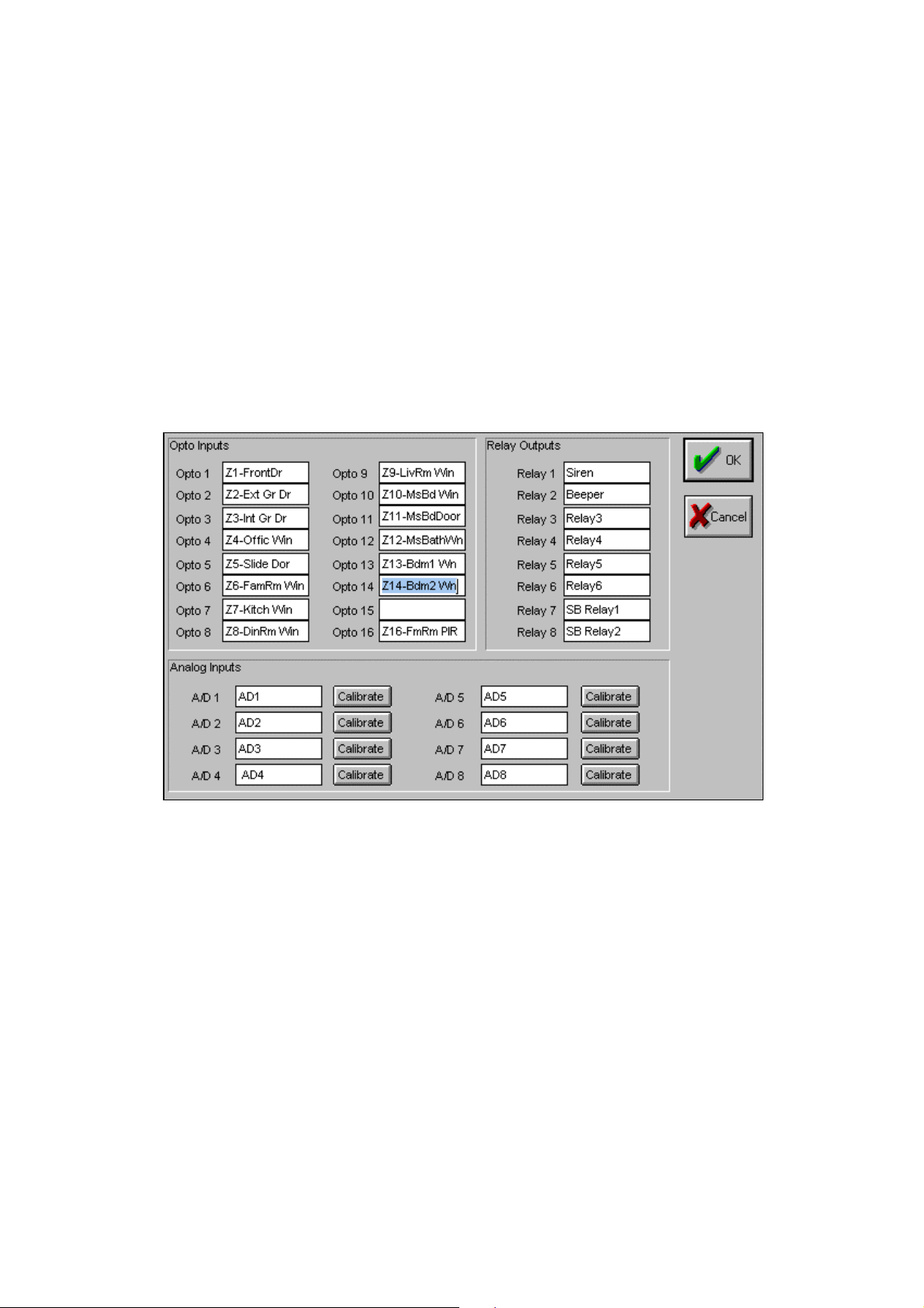
The dialog box appears allowing you to enter names for each IO connection. Each name corresponds to a connection on the
AUTOMATE DOMOTIQUE or IO-Xpander, which has 16 opto-isolated inputs, 8 SPST relays(see appendix for ratings) and
8 8-bit Analog-Digital inputs.
24
Page 28

Analog Inputs
The Analog inputs connect internally to an Analog to Digital Converter that converts analog voltages into a digital
representation compatible with AUTOMATE DOMOTIQUE. The A/D converters are 8 bit (range: 0-255) with an input
voltage range of 0-5 volts DC. This gives a resolution of approximately 20mV/bit (256 x 20mV = 5V). When AUTOMATE
DOMOTIQUE reads an A/D input, it will read a value in the range of 0-255, which represents a voltage from 0-5 applied to
the input. The table below shows some typical input voltages and shows what AUTOMATE DOMOTIQUE will read.
Input Voltage AUTOMATE
DOMOTIQUE
0 volt 0
1 volt 51
2.5 volt 128
4 volt 205
5 volt 255
Table 1: Analog Input Voltages
Calibrating
Calibration can be done through an external gain/offset
circuit or done through software. There are tradeoffs
using either method, if resolution is important the
external gain/offset circuit is preferred, if
resolution/accuracy is not as important (there is no
general rule of thumb, each application is different and
the tradeoffs must be examined on a case by case basis)
the software gain/offset may be acceptable.
Lets suppose you are going to measure temperature using
an AE1000 Wall plate temperature sensor. The AE1000
temperature sensor output voltage is linearly
proportional to the Fahrenheit temperature (10.0
mV/degree F and has a range from +32 to +212 degrees
F).
Assume the temperature being measured is 72? F. The
LM34D will output 720mV (72? x 10mV/degree). AUTOMATE DOMOTIQUE will read this 720mV and the digital
representation will be 36.
A/D resolution-20mV/bit: 720mV ? (20mV/bit) = 36
So, AUTOMATE DOMOTIQUE reads '36' when the temperature is 72?. It would be nice if the value AUTOMATE
DOMOTIQUE read was the same as the temperature. The two ways of doing this could be:
1. Build a 2x amp to convert the 720mV to 1400mV (1400mV / (20mV/bit) = 72)
2. Multiply the value read by AUTOMATE DOMOTIQUE by 2 (36 x 2 = 72), a gain of 2
Option 2 requires the least amount of work, but the resolution of the A/D converter is multiplied by 2 as well, going from
20mV/bit to 40mV/bit. To use the option 2 approach, the gain can be increased by software from within the Define | IO-
Xpander dialog boxes. Every A/D input can be calibrated with a software gain and offset. The gain will actually multiply the
A/D value and the offset will be added to the result. Using the previous AE1000 example, let’s say a gain of 2 will give a
value of 70 at 72 degrees. It is not 72 as would be expected due to many factors, wiring capacitance, AE1000 accuracy, etc.
By specifying an offset of 2, this will bring the value in line with the temperature. The formula for scaled A/D is:
25
Page 29

scaled_value = (raw_A/D_value x gain) + offset
If you do not need a gain factor, be sure to set the gain to 1 and offset to 0.
NOTE1: You may use Define IO any time you add another IO -Xpander, change connections or
rename ports. Note that if you do make a change, such as swapping 2 inputs, you will
need to re-download the schedule before the changes take effect.
NOTE2: Connect ANALOG GROUND to GROUND when using the on-board 5VDC Power source to
power analog devices.
26
Page 30

Digital Inputs
When using Digital Inputs, be sure the jumpers are in the correct position for the application.
Normally Open or
Normally Closed
Switch or Contact
Figure 1: Digital Input
27
Page 31

Line 2
Line 1
Relay Outputs
Each Relay Output has three terminals: “NO” (normally open), “NC” (normally closed), and “C” (common). The NO is
connected to C when the relay is ON. NC is connected to C when the relay is OFF. In Figure 2: Relay Connections, two
relays are used to allow a single-line cordless phone to switch between two different phone lines. The cordless base is
normally connected to Line 1 (Relay 1 and Relay 2 de-activated). When Relay 1 and Relay 2 are both activated, it connects to
Line 2.
CORDLESS
PHONE
BASE
Tel
Tel
Relay-1
NO C NC
Relay-2
NO C NC
Figure 2: Relay Connections
28
Page 32

Using the Event Editor
ToolBox
The ToolBox contains functions most frequently used when creating and editing schedules. It is located at the right side of
the Event window.
Creating an Event
New Event
Selecting the [New] button will bring up the New Event box. You will be able to customize the Event to be an IF/THEN,
IF/THEN/ELSE or FAST EVENT type, define the Event’s logic type as AND or OR, and insert the new Event before or after
the current highlighted event.
Fast Events
Events triggered by X10 ON/OFF commands or Digital Inputs (AUTOMATE DOMOTIQUE 's) going ON/OFF. These
events are executed immediately when triggered regardless of schedule size. Note that there can only be 1 Fast Event for a
given trigger.
Menu Item Description
Name The name of the Event. This name will appear in the schedule
Event Type The type of Event that you want to create. IF-THEN, IF-THEN-ELSE or FAST EVENT.
Always If the Always checkbox is selected, AUTOMATE DOMOTIQUE will always execute the actions if the
?
conditions are met. If not selected, AUTOMATE DOMOTIQUE will not execute any action unless the
conditions have changed since the last time the Event was evaluated.
Logic Type The logic type of the Event, AND or OR.
Insert Point This will place the new Event above or below the Event that is currently highlighted.
After selecting [OK], an empty Event will be inserted into your schedule.
Event - Add
You can add IF Conditions or THEN Actions to an Event by moving the highlight bar to where you want the statement to be
inserted.
If you want to add an IF statement, move the highlight bar to the IF section of the Event, that is between the ‘EVENT’ and
the ‘Then’ lines, and press the [ADD] button in the ToolBox. The ‘IF Condition’ popup menu will appear and by using your
mouse or the arrow keys on the keyboard, move to the type of IF Condition you want and press the <Enter> key or click [OK]
with your mouse.
To add a THEN statement, move the highlight bar to the THEN or ELSE section of the Event, then press the [ADD] button in
the ToolBox. The ‘THEN Action’ popup menu will appear and by using your mouse or the arrow keys on the keyboard,
move to the type of Action you want and press the <Enter> key or click with your mouse.
Event - Edit
To Edit an Event (IF Condition or THEN/ELSE Action), move the highlight bar to the item to be edited and select the
Toolbox [Edit] button (or double-click the left mouse button on the line to be edited). A dialog box with the information from
that line will appear and allow you to edit it.
29
Page 33

Event - Delete
To Delete an IF Condition or THEN/ELSE Action, move the highlight bar to the item you want to delete and select the
Toolbox [Delete] button.
Editing an Event
To modify an Event, move the highlight bar to the Event Name, and select the [EDIT] button in the ToolBox (or double click
the left mouse button). The Event Definition box will appear with the name, event type and logic type fields filled in. When
you are done with your changes, press the [OK] button to save. By pressing the <ESC> key or the [Cancel] button, any
changes are discarded.
Note when changing from an IF -THEN-ELSE type Event to an IF -THEN type Event, all of the
actions after the ELSE statement must be deleted before it can be changed
Deleting an Event
To delete an Event, place the highlight bar on the Event Name and select the [Delete] button in the ToolBox.
30
Page 34

IF Conditions
An Event uses IF Conditions to decide whether to do the THEN or ELSE actions. IF Conditions can be based on time, date,
sunrise/sunset, state of an X-10 device, received X10 sequence, received infrared, timers, variables, flags, digital inputs,
analog inputs, relay outputs, ASCII input and system variables (first schedule pass, X10 loss, ac power loss, power restored).
To add an IF Condition to an Event, move the highlight bar in the IF section of the Event and select the [ADD] Toolbox
button. A pop-up menu will appear allowing you to choose the type of IF condition. Select what type of IF Condition you
want with the mouse. A dialog box will appear and allow you to fill in the information for the IF Condition that was chosen.
X-10 Device State
Selecting X-10 Device State from the menu will open the X-10 Device Pick box. This IF condition will be TRUE if the state
of the X-10 Device is the same as the state chosen from the dialog box. After completing the form, press [OK] to enter the
new information into the schedule, [ADD] to enter the new information and return to the X10 Device pick box for more
entries, or the [CANCEL] to escape without saving anything.
What is it AUTOMATE DOMOTIQUE monitors the Powerline and as X-10 commands are received, it updates its
internal state table of all 256 X-10 devices. The three states that AUTOMATE DOMOTIQUE keeps track
of are ON, OFF and IDLE. You can compare the state of any X-10 device to trigger an Event.
How Used When used in the schedule, AUTOMATE DOMOTIQUE will compare the state of the X-10 device stored
in AUTOMATE DOMOTIQUE, against the state chosen in the dialog box. If the states match, this IF
statement will be true.
Menu Choices Description
ON If the device chosen is ‘ON’, this statement will be true.
OFF If the device chosen is ‘OFF’, this statement will be true.
IDLE If the device selected is in ‘IDLE’ mode, this statement will be true.
NOT OFF This condition will be true if the specified module (house and unit code) is either ON or IDLE. It will be
false if the module is OFF.
NOT ON This condition will be true if the specified module (house and unit code) is either OFF or IDLE. It will be
false if the module is ON.
NOT IDLE This condition will be true if the specified module (house and unit code) is either ON or OFF. It will be
false if the module is IDLE.
Enabled This condition will be true if the specified module (house and unit code) is ENABLED in the DEFINE-X10
DEVICE database. It will be false if the module is DISABLED.
Disabled This condition will be true if the specified module (house and unit code) is DISABLED in the DEFINE-
X10 DEVICE database. It will be false if the module is ENABLED.
DimLevel ==## This condition will be true if the specified module's (house and unit code) current level (0 to10) is equal to
## (specified number). It will be false if not.
DimLevel <= ## This condition will be true if the specified module's (house and unit code) current level (0 to 10) is less than
or equal to ## (specified number). It will be false if the level is greater than ##.
DimLevel >= ## This condition will be true if the specified module's (house and unit code) current level (0 to 10) is greater
than or equal to ##. It will be false if the level is less than ##.
PresetLevel ==## This condition will be true if the specified module's (house and unit code) Preset level (1 to 31) is equal to
## (specified number). It will be false if not.
PresetLevel <=## This condition will be true if the specified module's (house and unit code) Preset level (1 to 31) is less than
or equal to ## (specified number). It will be false if not.
PresetLevel >=## This condition will be true if the specified module's (house and unit code) Preset level (1 to 31) is greater
than or equal to ## (specified number). It will be false if not.
31
Page 35

What is the IDLE State:
AUTOMATE DOMOTIQUE keeps track of the current state of all 256 X-10 devices in a place called a state table. The device
state can be ON, OFF, or IDLE. A visual readout of the state table is provided by the MegaController display.
The ON or OFF state is obvious, but what is this IDLE state, and why is it needed? It can’t be sent or received on the power
line, it isn’t part of the X-10 modules or controllers, and it only exists inside the AUTOMATE DOMOTIQUE, yet it’s
extremely important and useful.
In concept, IDLE is neither ON nor OFF, but more like an “available for use” or “ready to go” state. The nature of X-10 and
some practical uses make it an ideal solution for a large number of situations.
When the AUTOMATE DOMOTIQUE passes through your schedule, one primary job it has is to look for a change in the
states of the X-10 devices. If it sees a change, it does whatever you told it to do. If nothing has changed, it ignores that scene
or event and continues on. If it didn’t act only on change of state, it would be sending out comman ds all the time.
Suppose you have the 8 button wireless remote control and the plug-in base receiver set for the M HouseCode. You decide
that when button 5 is pressed on or off, you want the study light and the fireplace spotlight to turn on or off. They’re both
controlled by wall switches across the room, one assigned A-7 , and one assigned G-3 (doesn’t matter what they are assigned
to!).
Easy to program into the AUTOMATE DOMOTIQUE. Basically, you put it in like this:
EVENT Sample On
If
(X: Switch 1 M-5) is ON
Then
(X: Study Light A-7) ON
(X: Hallway Light A-2) ON
End
EVENT Sample Off
If
(X: Switch 1 M-5) is OFF
Then
(X: Study Light A-7) OFF
(X: Hallway Light A-2) OFF
End
Fine. Flows logically, easy to setup. You push button M-5 to ON, and they both turn on. You push M-5 to OFF, and they
both turn off. How is the AUTOMATE DOMOTIQUE interpreting this? It received M-5 ON, from your wireless controller,
which was a change to the state of M-5, so it rolled along turning on the lights you assigned on the other codes. The
AUTOMATE DOMOTIQUE passes through the schedule around many times a second, watching for a change to the state of
M-5. The next pass through your schedule, it checked M-5 for it’s current state (ON). Until it sees M-5 change, it doesn’t try
to turn on the lights again.
Now to turn the lights off. You push button M-5 to OFF, and they both turn off. When you sent M-5 OFF, the AUTOMATE
DOMOTIQUE received it and saw the change in the state of M-5, so it turned off both lights. Next time through the
schedule, it left everything alone.
So, it works the way you expect. What’s the problem? Where’s that IDLE state stuff come in? Let’s throw in a typical
monkey wrench. Your four-year old boy zips in while you’re still sitting there and punches the wall switch for the study
light, flipping it off manually. You push the button M-5 ON on your controller like you did originally, but this time the lights
don’t come on. Nothing happens. You try pushing it ON again a couple times, still nothing. You push it OFF, and now the
remaining light goes off. Now you push M-5 ON again, and finally both lights go ON. What’s going on here?
A limitation of X-10 devices is that most are one-way.. which means they can’t notify the AUTOMATE DOMOTIQUE when
they are turned on or off manually! The AUTOMATE DOMOTIQUE was still watching for a change to the state of M-5
(ON, in the example). When you pressed M-5 ON to flip the light back on that your child turned off manually, the
AUTOMATE DOMOTIQUE checked M-5, found it set to ON already, so it didn’t try to turn on the lights again. Not until
you pushed it off, changing the state, did it act on it.
So why not have AUTOMATE DOMOTIQUE always act on M-5 ON, every pass through the schedule, instead of watching
for the change in its state? In this example, it would then send an ‘ON’ command to the two lights, constantly, every pass
through the schedule. You wouldn’t be able to turn off the lights manually, not to mention the power line tied up with
constant X-10 commands.
32
Page 36

You could do some clever programming, setting flags and such, to get around this X-10 limitation, but it would be complicate
things quite a bit. Enter the IDLE state. If you could set the M-5 button to IDLE, which is neither ON nor OFF, it would
then be available for use . A push of M-5 ON at any time, (like after the child turned off the wall switch manually) would
then be a change in the state of M-5 (from IDLE to ON) and the AUTOMATE DOMOTIQUE would re-send the commands
to turn the lights on.
Let’s rewrite the example to set the state of M-5 to IDLE after each push:
EVENT Sample On
If
(X: Switch 1 M-5) is ON
Then
(X: Study Light A-7) ON
(X: Hallway Light A-2) ON
(X: Switch 1 M-5) Idle
End
EVENT Sample Off
If
(X: Switch 1 M-5) is OFF
Then
(X: Study Light A-7) OFF
(X: Hallway Light A-2) OFF
(X: Switch 1 M-5) Idle
End
Now each time that you push M-5 on your wireless controller, AUTOMATE DOMOTIQUE re-sends the ON or OFF
commands to your lights, even if they have been turned on or off manually. Since your event always sets the M-5 to IDLE
state after each time you push the button, any M-5 ON or OFF code coming in is a change to the M-5 state, so AUTOMATE
DOMOTIQUE will trigger the event.
You will find having the ability to set switches (such as M-5 in the example) and devices to the IDLE state (making them
available to be triggered), will make writing events into your schedule much easier than the fancy programming necessary to
otherwise cope with X-10 limitations.
Another way to write this example would be to use the X-10 Sequence. When an Event is using an X-10 Sequence, it is
waiting for an exact sequence of X-10 Commands on the Powerline, and they must happen within a certain amount of time.
Using X-10 Sequences in the previous example, the IDLE state is not needed. This is because the Event is looking for a
sequence of X-10 commands, not a state change, so there is no need to change the state of anything.
Let’s rewrite the example to look for a sequence instead of a state change:
EVENT Sample On
If
(XSEQ: M-5 M-ON) received within 4 seconds
Then
(X: Study Light A-7) ON
(X: Hallway Light A-2) ON
End
EVENT Sample Off
If
(XSEQ: M-5 M-OFF) received within 4 seconds
Then
(X: Study Light A-7) OFF
(X: Hallway Light A-2) OFF
End
Now each time that you push M-5 (sending M-5 M-ON) on your wireless controller, AUTOMATE DOMOTIQUE sees the
sequence and re-sends the ON commands to your lights, even if they have been turned on or off manually.
X-10 State vs. X-10 Sequence
X-10 State: The present status, ON/OFF/Idle, of the X-10 device at the time AUTOMATE DOMOTIQUE is looking at it in
a schedule.
33
Page 37

X-10 Sequence: A series of any valid X-10 transmissions, either HouseCode/UnitCode or HouseCode/FunctionCode, that
AUTOMATE DOMOTIQUE receives.
X-10 Sequence
Selecting X-10 Sequence from the menu will open the X-10 Sequence Box. This IF condition will be TRUE if AUTOMATE
DOMOTIQUE receives or transmits the X-10 Command sequence, in the exact order and within the time window that you
specify in the dialog box. After completing the form, press the [OK] button to enter the new information into the schedule, or
[CANCEL] to return without saving.
What is it AUTOMATE DOMOTIQUE monitors the Powerline and compares received only, transmitted only, or
either received/transmitted commands on the Powerline with the command(s) that you specify in the X10
Sequence box. A command sequence can consist of up to 6 X-10 commands and a time window that they
must occur in. An X-10 command sequence can consist of any X-10 commands, A1, C5, P-ON, F-OFF,
D-ALL UNITS OFF, etc.
How Used When used in the schedule, AUTOMATE DOMOTIQUE will monitor the Powerline and if the X-10
commands AUTOMATE DOMOTIQUE receives are the same as those you have specified, and they occur
within the time window, this statement will be TRUE.
Menu Choices Description
HouseCode The HouseCode used in the command
UnitCode The UnitCode used in the command if the UnitCode radio button is chosen
UnitCode Select a UnitCode command
ON Command Select the ON command
OFF Command Select the OFF command
Dim Command Select the DIM command
Bright Command Select the BRIGHT command
All Lights ON Select the All Lights ON command
All Lights OFF Select the All Lights OFF command
All Units OFF Select the All Units OFF command
Preset Command Select the Preset command and a preset level
Time Window The Time frame that the commands must occur in. Note that each X-10 command takes
approximately 1 second to send if sent with no delay in-between, so be sure to allow enough
time for all of the commands to be seen in the Time Window
[Add] This will add a command to the X-10 Sequence list where the highlight bar is positioned
[Replace] This will replace a command in the X-10 Sequence list where the highlight bar is positioned
with selections made
[Delete] This will delete the command that is highlighted in the list b ox
[OK] This will accept the choices made and add to the schedule
[Cancel] This will exit the X-10 Sequence dialog box without adding or modifying the schedule
Example: Using 1 UnitCode to control 4 different lights.
EVENT: lights 1
If
(XSEQ: A-1 A-OFF A-1 A-OFF) Received within 4 seconds
Then
(X:Lamp 1 B 1) ON
End
EVENT: lights 2
If
(XSEQ: A-1 A-OFF A-1 A-ON) Received within 4 seconds
34
Page 38

Then
(X:Lamp 2 B 2) ON
End
EVENT: lights 3
If
(XSEQ: A-1 A-ON A-1 A-OFF) Received within 4 seconds
Then
(X:Lamp 3 B 3) ON
End
EVENT: lights 4
If
(XSEQ: A-1 A-ON A-1 A-ON) Received within 4 seconds
Then
(X:Lamp 4 B 4) ON
End
If Timer
What is it These are the Timers that you have defined in the Device DataBase for use in your schedule. Timers are
countdown timers, meaning, once a timer is loaded, it will decrement every second until it reaches zero
(00:00:00), or is stopped by an Event. The maximum amount of time that can be loaded into a Timer is 18
hours, 12 minutes, 16 seconds (18:12:16). Once the Timer has been loaded, it will start counting down to
zero (00:00:00).
There are 4 states that a Timer can be in:
Expiring:
A Timer is Expiring when it changes from 00:00:01 to 00:00:00. The Timer will stay in the
Expiring state for one complete pass through your Schedule, then change to the Stopped state.
Running:
Not Running:
Stopped:
While a Timer is counting down, it is in the Running state.
While a Timer is not counting down (opposite of Running).
A Timer can get into the Stopped state 1 of 2 ways. 1) The Timer can be stopped using the
Timer Stop Action in an Event, or 2) After the Timer reaches the Expiring state, it goes into the Stopped
state.
Cleared:
After every Schedule download, all Timers are put into the ‘Cleared’ state. Note that this is
different from the ‘Stopped’ state, it cannot be tested for in an Event. Timers will stay in the ‘Cleared’
state until an Event changes its state. It may be necessary to create an ‘Initialization Event’ that after a
download, puts the Timers into a state other than ‘Cleared’.
Example:
EVENT: Initialization Event
If
(X: N-16) is ON
or (X: N-16) is OFF
Then
(T:HallwayLt) STOP
End
Example: Timer is loaded with 15 seconds
Timer Value Timer State
00:00:00 Stopped
00:00:15 Running (just loaded with 15 seconds)
00:00:14 Running
. . .
00:00:01 Running
00:00:00 Expiring (Timer stays in this state for 1 pass through schedule)
00:00:00 Stopped
How Used Timers can be used in an Event to provide 1-second resolution timed events. The Timers can be stopped,
started, cleared or loaded with a new countdown time at any time.
35
Page 39

Menu Choices Description
Expiring If the Timer is Expiring (the Timer counts down to 00:00:00), this IF statement will be true.
Running If the Timer is running, this IF statement will be true.
Not Running If the Timer is NOT running, this IF statement will be true.
Stopped If the Timer has been stopped, this IF statement will be true.
Example:
EVENT: Hallway Motion
If
(XSEQ: A-14 A-ON) Received within 4 seconds
Then
(T:HallwayLt) Load 0:02:00
(X:Hall Light) ON
End
EVENT: Hallway Turn OFF
If
(T:HallwayLt) is Expiring
Then
(X:Hall Light) OFF
End
In this example, when motion is detected in the hallway, the X-10 command A-14 A-ON is sent. When AUTOMATE
DOMOTIQUE receives this command, the “HallwayLt” timer gets loaded with 2 minutes and the hallway light turns ON (in
EVENT “Hallway Motion”). When the timer reaches 0:00:00 (Expiring), the second EVENT “Hallway Turn OFF” will turn
the hallway light OFF.
Note Timers are re -triggerable, that is, while they are running, a new load value can
be loaded into the timer. In the previous example, if the timer had counted d own to
say, 10 seconds, and there was motion in the hallway again causing the A -14 A-ON command
to be sent again, the “HallwayLt” timer would be reloaded with 2 minutes
36
Page 40

If Flag
What is it Flags are variables that have 3 states, Set , Clear or I DLE. Events can use Flags to communicate with each
other.
How Used When used in the schedule, AUTOMATE DOMOTIQUE will check the state of the Flag and compare it to
that specified.
Menu Choices Description
Set If the Flag’s state is Set, this IF statement will be true
Clear If the Flag’s state is Clear, this IF statement will be true
IDLE If the Flag’s state is IDLE, this IF statement will be true
Not Set If the Flag’s state is NOT Set, this IF statement will be true
Not Clear If the Flag’s state is NOT Clear, this IF statement will be true
Not IDLE If the Flag’s state is NOT IDLE, this IF statement will be true
Example: Tracking System
EVENT: Tracking 1
If
(X:Hall Motion A-14) is ON
Then
(F:Hallway Track) SET
End
EVENT: Tracking 2
If
/* going from hallway to study */
(X:Study Motion) is ON
and (F:Hallway Track) is SET
Then
(X:Hall Light) OFF
(X:Study Light) ON
(F:Hallway Track) CLEAR
(F:Study Track) SET
End
EVENT: Tracking 3
If
/* going from study to hallway */
(X:Hall Motion A-14) is ON
and (F:Study Track) is SET
Then
(X:Study Light) OFF
(X:Hall Light) ON
(F:Study Track) CLEAR
(F:Hallway Track) SET
End
In the tracking example above, flags are used to keep track of the last room that was occupied. Using motion detectors and
keeping track of the last room that was occupied (with flags), a sophisticated tracking system can be developed that will turn
the lights on in the room that you walk into, as well as turn off the lights in the room you were just in.
If Variable
What is it Variable values can range anywhere from 0 to 255. The Variable can be compared against a value, A/D
Input, HVAC temperature or SetPoint, or another Variable and used to trigger an Event.
How Used When used in the schedule, the Variable will be compared against the type that you specify.
37
Page 41

Compare Options
Equal to Variable is equal to
Less than Variable is less than
Greater than Variable is greater than
Less than/Equal to Variable is less than or equal to
Greater than/Equal to Variable is greater than or equal to
Not Equal to Variable is not equal to
Changes Value This condition will be true if the value changes since the last schedule pass.
Increases in Value This condition will be true if the value has increased since the last schedule pass
Decreases in Value This condition will be true if the value has decreased since the last schedule pass
Bits 0-7 Set These conditions check to determine if the specified bit is set (has a value of one). Variables/Analog
Inputs/HVAC values are stored as 8-bit numbers ranging from 0 to 255. Bit 0 is the least significant bit
(LSB) and bit 7 is the most significant bit (MSB). Here are some examples:
If the variable = 0(decimal) (00000000b), no bits are set.
If the variable = 8(decimal) (00001000b), only bit 3 is set.
If the variable = 6(decimal) (00000110b), bits 1, and 2 are set.
If the variable = 192(decimal) (11000000b), bits 7 and 6 are set.
Bits 0-7 Not Set These conditions check to determine if the specified bit is NOT set (has a value of zero). Variables /Analog
Inputs/HVAC values are stored as 8-bit numbers ranging from 0 to 255. Bit 0 is the least significant bit
(LSB) and bit 7 is the most significant bit (MSB).
Compare Against
Value If selected, the Variable highlighted in the listbox will be compared against a value that can range from 0 to
255 (see picture above).
Analog Input If selected, the Variable highlighted in the listbox will be compared against an Analog Input shown in the
listbox to the right.
Variable If selected, the Variable highlighted in the listbox will be compared against a Variable picked from the
listbox to the right.
HVAC If selected, the Variable highlighted in the listbox will be compared against an HVAC value shown in the
listbox to the right.
IF Macro
What is it An IF Macro is a set of IF Conditions that has a name (like an Event with no THEN actions) and can be
used multiple times in a Schedule. Each IF Macro has a logic type associated with it, similar to the logic
type of an Event. If the logic type is AND, then all of the conditions must be true for the IF Macro to be
true. If the logic type is OR, the only 1 of the conditions needs to be true for the IF Macro to be true.
How Used When used in the schedule, AUTOMATE DOMOTIQUE will evaluate all of the IF Conditions in the IF
Macro. If the conditions meet the requirements of the IF Macro (AND/OR), the IF Macro statement will be
true.
Example 6 IF Macro Example: Gone@Night
IF MACRO:
If
(X:Alarm Armed) is ON
and After SunSet SMTWTFS
End
Example 7 Using IF Macro “Away at Night”
38
Page 42

EVENT: Random Lights1
If
(IF MACRO:Gone@Night)
and Time is 8:30 PM SMTWRFS Security Mode
Then
(X:Kitchen Lights) ON
End
EVENT: Random Lights2
If
(IF MACRO:Gone@Night)
and Time is 9:30 PM SMTWRFS Security Mode
Then
(X:Dining Lights) ON
End
In the examples above, an IF MACRO was used by both Events to check if the Alarm is Armed and if it is dark outside.
Once you define an IF MACRO, you may use it in any Event, any number of times.
If Comment
What is it A Comment can be a description or a note. It does not affect the way the Event works in any way.
How Used When used in the schedule, a Comment can add some description of what the Event is doing. A Comment
can be placed anywhere within the Event, but not between Events.
If Time
What is it A Time condition is a time that you want something to happen.
How Used When used in the schedule, AUTOMATE DOMOTIQUE will compare the current time of day to the time
you choose. If the times match, the IF statement will be TRUE.
Menu Choices
Description
Equal to If the “Equal to” radio button is pressed, the current time must be equal to the time you have entered and
match the days you chose in order to be considered true.
Before If the “Before” radio button is pressed, the current time must be
specified time
After If the “After” radio button is pressed, the current time must be
Midnight
Days By selecting the checkbox next to the days, you can specify the day(s) this condition must occur.
Security Mode Security Mode will add or subtract a random amount of time from the time entered. Every day a new
*?
random number is generated and added to the time entered. This feature is useful to make lights go on or
off at random times to give a more ‘lived in’ look.
Automate Domotique’s day begins at midnight and ends at 11:59 PM. If you are using an IF statement such as ‘Time is after
8:00 PM’, it will be true from 8:00 PM until midnight (when Automate Domotique’s day ends).
As an example, Otto would like to turn his outdoor lights on when he presses the button on his mini-controller, but only if it
is at night (after 8:00PM for this example).
EVENT Outdoor lights
If
Time is After 8:00 PM SMTWTFS
and (X:minibutton) is ON
Then
(X:Outdoorlgts) ON
End
AFTER Midnight
and
, and match the days you chose, in order to be considered true.
AFTER the specified time
(11:59:59 PM), and match the days you chose, in order to be considered true.
BEFORE the
and
BEFORE
39
Page 43

This is fine until Otto stays up after midnight one evening. Once the time is after midnight (11:59 PM), he could not turn his
lights on. He solved this by adding another Time condition to his Event.
EVENT Outdoor lights
If
Time is After 8:00 PM SMTWTFS
or Time is Before 6:00 AM SMTWTFS
-AND (X:minibutton) is ON
Then
(X:Outdoorlgts) ON
End
Now, if is after 8pm or before 6am, and Otto presses the button, his light will turn on.
NOTE: You must use or logic when times cross over midnight to the next day.
If Time Label
What is it A Time Label is a time that has descriptive name. It can be used to give a meaningful name to a particular
time.
Example: “Wakeup” could mean 5:45 AM . MTWTF .
“Dusk” could mean 30 minutes after SunSet
How Used When used in a schedule, the current time of day will be compared to the time in the Time Label. If the
times meet the requirements that have been entered into the Time Label, the IF statement will be TRUE.
Menu Choices Description
Equal To
Before
The current time and day must EQUAL the TimeLabels time and day exactly.
If selected, the current time must be
AFTER Midnight
and
BEFORE the TimeLabels time
and the days
must match.
After
If selected, the current time must be
AFTER the TimeLabels time
and
BEFORE Midnight
and the days
must match.
If Date
What is it Dates are a particular Month and Day. They are used to control an Event’s actions to a particular day of the
year, or a range of days. An example would be changing heating and cooling patterns based on the seasons.
How Used When used in the schedule, AUTOMATE DOMOTIQUE will compare the current date against the month
and day that you have specified into your schedule.
Menu Choices Description
Equal To Date
Before Date
When the current date becomes
When the current date is
TRUE, otherwise it is FALSE.
EQUAL
to the date specified, this IF statement will be TRUE.
AFTER January 1st
and
BEFORE the specified date
, this IF statement will be
After Date
When the current date is
AFTER the specified date
and
BEFORE January 1st
TRUE, otherwise it is FALSE.
Even Days Condition is true if the current day of the month is an even number (2,4,6, etc.).
Odd Days Condition is true if the current day of the month is an odd number (1,3,5, etc.).
Season – Spring Condition is true if the current date is between March 20 and June 20.
40
, this IF statement will be
Page 44

Season – Summer Condition is true if the current date is between June 21 and September 21.
Season – Fall Condition is true if the current date is between September 22 and December 20.
Season – Winter Condition is true if the current date is between December 21 and March 19.
AM Condition is true if current time is between 12:00 AM (midnight) and 11:59 AM.
PM Condition is true if current time is between 12:00 PM (noon) and 11:59 PM.
Daytime Condition is true if current time is between 6:00 AM and 5:59 PM.
Nighttime Condition is true if current time is between 6:00 PM and 5:59 AM.
Light Condition is true if current time is after sunrise and before sunset.
Dark Condition is true if current time is after sunset and before sunrise.
As an example, Otto would like his Christmas lights to come on at 6:00 PM everyday if it’s after December 15th.
EVENT Christmaslights
If
Date is After Dec 15
and Time is 6:00 PM SMTWTFS
Then
(X:Christmaslgts) ON
End
The Christmas lights would be turned on at 6:00 PM everyday as long as it is after December 15th. When the date becomes
January 1st, the lights would not be turned on since this is the start of another year.
If Otto wanted to have his lights come on from December 15th - January 5th, his Event would look like this:
EVENT Christmaslights
If
Date is After Dec 15
or Date is Before Jan 5
-AND Time is 6:00 PM SMTWTFS
Then
(X:Christmaslgts) ON
End
NOTE: You must use or logic when dates cross over to the next year.
If SunRise/SunSet
Selecting SunRise/SunSet from the menu will open the SunRise/SunSet box. You can choose to have this IF condition be
TRUE if the current time is Equal to, Before or After SunRise or SunSet on a particular day. After completing the form,
press the [OK] button to enter the new information into the schedule, or the [CANCEL] to return without saving anything.
What is it Everyday at midnight, AUTOMATE DOMOTIQUE re-calculates the SunRise and SunSet times, based on
your location. Your schedule can use these times to control Events that you want to be based on SunRise or
SunSet times. The calculated SunRise and SunSet times has an accuracy of plus or minus 10 minutes from
the true SunRise or SunSet.
How Used When used in the schedule, AUTOMATE DOMOTIQUE will compare it’s current time to the calculated
SunRise or SunSet time and also compare the current day of the week.
Menu Choices Description
Equal To If the current time is EQUAL to the SunRise or SunSet time on the day(s) selected, this IF statement will be
true.
Before
If the current time is
AFTER Midnight
and
BEFORE the SunRise or SunSet time
on the day(s) selected,
this IF statement will be true.
41
Page 45

After If the current time is
AFTER the SunRise or SunSet time
and
BEFORE Midnight
on the day(s) selected,
this IF statement will be true.
SunRise If selected, AUTOMATE DOMOTIQUE will use the calculated SunRise time in this statement.
SunSet If selected, AUTOMATE DOMOTIQUE will use the calculated SunSet time in this statement.
Security Mod
?
When selected, AUTOMATE DOMOTIQUE will add the security offset to the SunRise or SunSet time.
e
This will change the SunRise/SunSet time by adding/subtracting the Security Offset to the time.
Note:
For SunRise/SunSet calculations to be ac curate, the Longitude, Latitude and Time
Zone information must be correct.
If ASCII In
What is it ASCII text data can be sent to AUTOMATE DOMOTIQUE and used to trigger an Event. The ASCII text
can be up to 32 characters in length and must be terminated with a carriage return.
How Used The ASCII text sent to AUTOMATE DOMOTIQUE can
match a range of characters or test for a number of characters. Programs other than Event Manager can
send ASCII text to AUTOMATE DOMOTIQUE to trigger Events. Select the AUTOMATE
DOMOTIQUE COM port (“Source”) which will receive the ASCII data.
Menu Choices Description
Input Data Match
The ASCII input string must
match exactly
statement
Input Data Range Match
This condition is used to compare the input string or a portion of it to certain characters.
Example: Match ‘ZZZZZ’ starting at char X
The symbol meanings are:
match exactly
(upper/lower case, spaces, etc.) the ASCII In
(upper/lower case, spaces, etc.),
X refers to the location in the string of the first character to compare (i.e., the character number).
ZZZZZZZZ are the characters to compare the received data to. The condition is true if all
characters match exactly, false is any do not match.
Number of characters received equals ##
Condition is true if the number of characters received (serial string length) is equal to the
value.
Number of characters received is less than ##
Condition is true if the number of characters received (serial string length) is less than or
equal to the value.
Number of characters received is greater than ##
Condition is true if the number of characters received (serial string length) is greater than
or equal to the value.
EVENT: ASCII Input Example
If
ASCII-In: ‘Hello Otto’]
Then
(X:Study Light A7) ON
End
Example 8 ASCII In
42
Page 46

In the previous example, when the ASCII text ‘Hello Otto’ is sent to AUTOMATE DOMOTIQUE, it will trigger the Event to
turn the Study Light ON.
2) Suppose an alarm system sends ASCII text messages for its alarm states. Typical messages the alarm would send are:
Alarm Violation
Alarm Armed
Alarm Ready
To keep track of Alarm states, ASCII In conditions are used.
Example 9 ASCII In
EVENT: Alarm Status
If
ASCII-In: Match 'Alarm' starting at character number 1
Then
|-If
| ASCII-In: Match 'Armed' starting at character number 7
|Then
| " Armed state == 1 "
| (V:Alarm State) ) LOAD with 1
|-End
|-If
| ASCII-In: Match 'DisArmed' starting at character number 7
|Then
| " Disarmed state == 2 "
| (V:Alarm State) ) LOAD with 2
|-End
|-If
| ASCII-In: Match 'Violated' starting at character number 7
|Then
| " Violated state == 3 "
| (V:Alarm State) ) LOAD with 3
|-End
End
3) Suppose you have a weather station that reports the current temperature in the following format:
Temp = 85 degrees
To match the string and convert the value to a variable the following event could be used.
Example 10 ASCII In
EVENT: Convert Temperature
If
ASCII-In: Match 'Temp = ' starting at character number 1
Then
Put value of received char #8-9 into user_VAR
(V:Temperature) load with user_VAR
End
Note: The serial port of AUTOMATE DOMOTIQUE will not echo any ASCII text that is sent
to it. The ASCII text input to AUTOMATE DOMOTIQUE must be terminated with a carriage
return (linefeeds are not needed).
AND Statement
Selecting AND Statement from the menu will add an AND statement to the Event.
What is it AND statements are used in OR type Events.
43
Page 47

How Used You can use the AND statement to create compound OR/AND type Events.
Example 11 AND Statement
EVENT: OR/AND Example
If
(X:P1 ) is ON
or (X: P2 ) is ON
-AND (X:P3 ) is ON
or (X: P4 ) is ON
Then
(X: B7) ON
End
In the previous OR/AND example, if either P1 or P2 is ON, AND, if either P3 or P4 is ON, then turn B7 ON.
OR Statement
Selecting OR Statement from the menu will add an OR statement to the Event.
What is it OR statements are used in AND type Events.
How Used You can use the OR statement to create compound AND/OR type Events.
Example 12 OR Statement
EVENT: OR/AND Example
If
(X:P1 ) is ON
and (X: P2 ) is ON
-OR (X:P3 ) is ON
and (X: P4 ) is ON
Then
(X: B7) ON
End
In the previous AND/OR example, if P1 and P2 is ON, OR, if P3 and P4 is ON, then turn B7 ON.
If System Variables
What is it
How Used The System Variables can be used to trigger an Event
System Variables are variables internal to AUTOMATE DOMOTIQUE that can be used in Schedules.
Menu Choices Description
Power-Restore This variable is set after power is restored after a power failure. It will be set for one pass through the
Schedule, then it will be cleared. You may want to use this variable to force certain devices to an known
state after power comes back on.
First Pass This variable is for the first pass through a Schedule after a DownLoad. You may want to use this variable
to force certain devices to an known state after a new DownLoad.
X10 Signal Loss This variable is set when the X10 zero cross signal is not received. This can occur if the TW523 PLI is
unplugged or if the AC power powering the TW523 goes out. This variable could be used to detect a power
failure if running on battery backup.
Example 13 Power Restore
EVENT: Power Restore Example
If
Power-Failure
44
Page 48

Then
/* Reset critical Devices */
(X:Hot Tub B-5) OFF
(X:Sprinklers D-1) OFF
End
EVENT: First Pass Example
If
First Pass
Then
/* Setup Certain Devices */
(F:Security Active) OFF
(X:Modem M-1) ON
End
EVENT: X10 Loss Example
If
X10 Loss
Then
LOG ‘ AC Power Loss’
End
If Digital Input
Digital Inputs are ‘ON’ when sufficient voltage (4 - 24v ac or dc) is applied between the two inputs.
How Used When used in a schedule, AUTOMATE DOMOTIQUE will compare If the condition is met, the IF
statement will be TRUE.
Menu Choices Description
ON This IF statement will be TRUE as long as a voltage is applied to the Digital Input selected in the list box.
OFF This IF statement will be TRUE as long as there is no voltage to the Digital Input selected in the list box.
Toggle The IF statement will be TRUE if the Digital Input changes from either ON to OFF or OFF to ON, it
doesn’t matter which way it changes, only that it did change.
Goes ON This IF statement will be TRUE when a voltage is first applied to the Digital Input selected in the list box.
It is equivalent to TOGGLES and IS ON.
Goes OFF This IF statement will be TRUE when a voltage is first removed from the Digital Input selected in the list
box. It is equivalent to TOGGLES and IS OFF.
If Analog Inputs
What is it An Analog Input measures voltages that range from 0 to 5 volts DC. The converted value can range
anywhere from 0 to 255. The Analog value can be compared against a value, Analog Input, HVAC
temperature or SetPoint, or Variable and used to trigger an Event.
How Used When used in the schedule, the Analog Input will be compared against the type that you specify.
Compare Options
Equal to Analog Input is equal to
Less than Analog Input is less than
Greater than Analog Input is greater than
Less than/Equal to Analog Input is less than or equal to
Greater than/Equal to Analog Input is greater than or equal to
Not Equal to Analog Input is not equal to
45
Page 49

Changes Value This condition will be true if the value changes since the last schedule pass.
Increases in Value This condition will be true if the value has increased since the last schedule pass
Decreases in Value This condition will be true if the value has decreased since the last schedule pass
Bits 0-7 Set These conditions check to determine if the specified bit is set (has a value of one). Variables/Analog
Inputs/HVAC values are stored as 8-bit numbers ranging from 0 to 255. Bit 0 is the least significant bit
(LSB) and bit 7 is the most significant bit (MSB). Here are some examples:
If the Analog Input = 0(decimal) (00000000b), no bits are set.
If the Analog Input = 8(decimal) (00001000b), only bit 3 is set.
If the Analog Input = 6(decimal) (00000110b), bits 1, and 2 are set.
If the Analog Input = 192(decimal) (11000000b), bits 7 and 6 are set.
Bits 0-7 Not Set These conditions check to determine if the specified bit is NOT set (has a value of zero). Variables /Analog
Inputs/HVAC values are stored as 8-bit numbers ranging from 0 to 255. Bit 0 is the least significant bit
(LSB) and bit 7 is the most significant bit (MSB).
Compare Against
Value If selected, the Analog Input highlighted in the listbox will be compared against a value that can range from
0 to 255 (see picture above).
A/D Device If selected, the Analog Input highlighted in the listbox will be compared against an A/D input shown in the
listbox to the right.
Variable If selected, the Analog Input highlighted in the listbox will be compared against a Variable picked from the
listbox to the right.
HVAC If selected, the Analog Input highlighted in the listbox will be compared against an HVAC value shown in
the listbox to the right.
If Relay Output
What is it The state of a Relay Output can be compared and used in a schedule.
How Used When used in a schedule, AUTOMATE DOMOTIQUE will test the state of a Relay.
Menu Choices Description
ON This IF statement will be TRUE if the Relay is in the ON state.
OFF This IF statement will be TRUE if the Relay is in the OFF state.
If Infrared
What is it When used in conjunction with the JDS InfraRed Xpander™, received Infrared Command Sequences and
Power Sensor Input states can be compared. AUTOMATE DOMOTIQUE monitors the InfraRed
Xpander™ and compares Infrared commands received with the command(s) that you specify in the IR
Sequence box. A command sequence can consist of up to 10 commands and a time window that they must
occur in. An IR command sequence can consist of any learned IR commands.
How Used First, configure the InfraRed Xpander™ using the Define | IR & IO | IRXpander setup screen. IR
Sequences can be used after IR codes have been learned into the InfraRed Xpander™. IR Power Sensor
states can be used after names have been assigned to the ports.
IR Sequence
An IR sequence is a number of IR commands received by the InfraRed Xpander™ within a time window.
IR Power Sensor
IR Power Sensors can be tested for ON and OFF states.
46
Page 50

If HVAC
These are the Thermostats that you have defined in Define | HVAC.
What is it The Thermostat’s SetPoint and Temperature can be compared against a value, Analog Input, another
HVAC temperature or SetPoint, or Variable and used to trigger an Event.
How Used When used in the schedule, the Thermostat’s SetPoint or Temperature will be compared against the type
that you specify.
Compare Options
Equal to SetPoint or Temperature is equal to
Less than SetPoint or Temperature is less than
Greater than SetPoint or Tempe rature is greater than
Less than/Equal to SetPoint or Temperature is less than or equal to
Greater than/Equal to SetPoint or Temperature is greater than or equal to
Not Equal to SetPoint or Temperature is not equal to
Changes Value This condition will be true if the value changes since the last schedule pass.
Increases in Value This condition will be true if the value has increased since the last schedule pass
Decreases in Value This condition will be true if the value has decreased since the last schedule pass
Bits 0-7 Set These conditions check to determine if the specified bit is set (has a value of one). Variables/Analog
Inputs/HVAC values are stored as 8-bit numbers ranging from 0 to 255. Bit 0 is the least significant bit
(LSB) and bit 7 is the most significant bit (MSB). Here are some examples:
If the SetPoint or Temperature = 0(decimal) (00000000b), no bits are set.
If the SetPoint or Temperature = 8(decimal) (00001000b), only bit 3 is set.
If the SetPoint or Temperature = 6(decimal) (00000110b), bits 1, and 2 are set.
If the SetPoint or Temperature = 192(decimal) (11000000b), bits 7 and 6 are set.
Bits 0-7 Not Set These conditions check to determine if the specified bit is NOT set (has a value of zero). Variables /Analog
Inputs/HVAC values are stored as 8-bit numbers ranging from 0 to 255. Bit 0 is the least significant bit
(LSB) and bit 7 is the most significant bit (MSB).
Compare Against
Value If selected, the SetPoint or Temperature highlighted in the listbox will be compared against a value that can
range from 0 to 255 (see picture above).
A/D Device If selected, the SetPoint or Temperature highlighted in the listbox will be compared against an A/D input
shown in the listbox to the right.
Variable If selected, the SetPoint or Temperature highlighted in the listbox will be compared against a Variable
picked from the listbox to the right.
HVAC If selected, the SetPoint or Temperature highlighted in the listbox will be compared against an HVAC value
shown in the listbox to the right.
47
Page 51

THEN/ELSE Actions
An Event will execute the THEN Actions when the condition(s) in the IF section are TRUE, and the ELSE Actions when the
condition(s) in the IF section are FALSE. THEN and ELSE actions can be any combination of X-10 commands, IR
commands, Relays (on/off), ASCII out, timers, flags, variables, logging a message and Then Macros.
To add a THEN or ELSE Action to an Event, place the highlight bar where you want to add the Action, in the THEN or
ELSE section of the Event, and press the [ADD] button.
A popup menu will appear allowing you to choose the type of THEN or ELSE action that you want. Select the type by
moving the highlight bar and pressing [Return] or click with the mouse. A dialog box will appear and allow you to fill in the
information needed.
X-10 Device
What is it These are the X-10 Devices that have been defined and can be used in your schedule. You can also enter
the HouseCode and UnitCode instead of using the X-10 Device DataBase.
How Used When used in the schedule, X-10 Devices can be turned ON, OFF, Dimmed or Brightened. Also global
commands such as All Lights On, All Lights OFF and All Units OFF can be sent.
Menu Choices Description
Set Module to IDLE Sets module to IDLE
ON Sets module to ON
OFF Sets module to OFF
Brighten # steps Brighten module # number of steps
Dim # steps Dim module # number of steps
All Lights ON Sends the All Lights ON command
All Lights OFF Sends the All Lights OFF command
All Units OFF Sends the All Units OFF command
Set to Level % Sets the module to a specific level using standard X-10 DIM/BRI commands
Preset to Level % Sets the module to a specific level using PreSet X-10 commands. Note the module must support
the Preset Dim command.
Micro-Bright # steps Micro Brighten the module # number of steps. This command is used with PCS style modules
only.
Micro-Dim # steps Micro Dim the module # number of steps. This command is used with PCS style modules only.
Status Request Sends the Status Request command
Status is ON Sends the Status=ON command
Status is OFF Sends the Status=OFF command
Hail Request Sends the Hail Request command
Hail Acknowledge Sends the Hail Acknowledge command
Toggle Module State Toggles the Modules State by sending an OFF command if the module is ON, an ON command
if the module is OFF.
Refresh Module Refresh the module by sending the current state of the module.
Enable Module This command enables a module that was previously disabled. A module must be enabled
before it will respond to any commands or transmit an X-10 signal via the schedule.
Disable Module A disabled module will not respond to any commands except for Enable Module. This
command can be used as a quick way to prevent any other part of your schedule from controlling
a module.
48
Page 52

Enable X10 ON Trigger Enables Fast Events based on the X10 ON Trigger. Fast Events Triggers are enabled by default.
This command will enable a trigger if it has been disabled.
Disable X10 ON Trigger Disables Fast Events based on the X10 ON Trigger. Fast Events Triggers are enabled by
default. This command will disable a trigger if it has been enabled.
Enable X10 OFF Trigger Enables Fast Events based on the X10 OFF Trigger. Fast Events Triggers are enabled by
default. This command will enable a trigger if it has been disabled.
Disable X10 OFF Trigger Disables Fast Events based on the X10 OFF Trigger. Fast Events Triggers are enabled by
default. This command will disable a trigger if it has been enabled.
Set State to ON This command sets the current state in the state table to ON, Level 11. It does not send any X-
10 signal over the power line.
Set State to OFF This command sets the current state in the state table to OFF, Level 12. It does not send any X-
10 signal over the power line.
Set State to IDLE This command sets the current state in the state table to IDLE. It leaves the level unchanged. It
does not send any X-10 signal over the power line.
Send ON Command Only This command sends the X10 ON command.
Send OFF Command Only This command sends the X10 OFF command.
Send BRI Command # times This command sends the X10 BRI command ## number of times.
Send DIM Command # times This command sends the X10 DIM command ## number of times.
Put current level into Variable This command puts the X-10 module's current light setting into the specified variable. If the
light is ON, its level (0 to 10) will be put in the variable. If the light is OFF, the variable is set
to 11. This command allows you to store the current level and later set the light back to it. See
the following commands for more information on setting the light to the level contained in a
variable.
Put 'Preset Dim' level into Variable This command puts the received preset dim level (1 to 32) into the specified variable. This
allows you to receive preset dim signals from devices that transmit them. Whenever the
controller receives a preset dim signal immediately following a house/unit code signal, it stores
the preset dim level for that house/unit code.
Set to level in Variable This command reads the value of the specified variable and sets the X-10 module to that level.
If the variable value is 0 to 10, the light will be turned on at that level. If the variable value is
11, the light will go off. Remember that a light ON at level 0 is not the same as OFF.
Set to Preset Level in Variable This command transmits a preset dim signal. The preset dim level (1 to 32) is taken from the
specified variable. Thus, if the variable contains the value 12, the X-10 signal "preset dim to
level 12, 35%, " is transmitted.
Timer/Delay
What is it These are the Timers that have you have defined in the Device DataBase. Timers are countdown timers,
meaning, once a Timer is loaded, it will decrement every second until it reaches zero (00:00:00), or is
stopped by an Event. The maximum amount of time that can be loaded into a Timer is 18 hours, 12
minutes, 16 seconds (18:12:16).
How Used Timers can be used in an Event to provide 1 second resolution time events. The Timers can be stopped and
started at any time as well as cleared.
Menu Choices Description
Stop Stop the Timer from running. If the timer is already stopped or expired, this command has no effect.
Start Start the Timer. If the timer is already running, this has no effect.
Clear Clear the Timer, this will set the timer to 00:00:00.
Load Load the Timer with the value specified. This will automatically start the Timer so no Start command is
needed.
49
Page 53

Delay Delay execution of this Event by the amount of time specified. When placed in an Event, the Delay
statement will delay execution of only that Event, until the delay time has expired.
Re-triggerable
If selected, the Delay will be re-triggerable. A re-triggerable Delay will be re-loaded automatically every
time the If condition(s) become true.
Example 14 Delay Example 1
EVENT Hallway Light
If
(XSEQ: A-14 A-ON) Received within 4 seconds
Then
(X:Hallway Light A-2) ON
DELAY 0:05:00 -Re-triggerable
(X:Hallway Light A-2) OFF
End
In this example, a motion sensor is setup to send the X-10 ‘A-14 A-ON’ command whenever motion is detected in the
hallway. When this sequence is received, the Hallway Light will turn ON, wait 5 minutes and then turn OFF.
But what happens if somebody is in the hallway for more than 5 minutes or walks through with 1 second left? Normally, the
Hallway Light will still turn off after 5 minutes. However, if you define the Delay as Re-triggerable, whenever the IF
Condition is true again (X10 SEQ: A14 A-ON is this example) the Delay would be re-loaded with 5 minutes.
Example 15 Delay Example 2
EVENT sprinklers
If
Time = 4:00 AM SMTWTFS
Then
(X:Sprinkler 1) ON
DELAY 0:06:00
(X:Sprinkler 1) OFF
(X:Sprinkler 2) ON
DELAY 0:04:00
(X:Sprinkler 2) OFF
(X:Sprinkler 3) ON
DELAY 0:12:00
(X:Sprinkler 3) OFF
End
In the example above, at 4:00 AM Sprinkler 1 will turn ON and the Event will Delay for 6 minutes. Sprinkler 1 will then turn
OFF, Sprinkler 2 will turn ON. After 4 minutes it will turn OFF and Sprinkler 3 will turn ON for 12 minutes and then turn
OFF.
Note: Delays that are used in one Event will have no e ffect on any other Event.
Flag
What is it Flags are used as variables or markers that have two states, Set or Cleared. Events can use Flags to
communicate with each other.
How Used When used in the schedule, AUTOMATE DOMOTIQUE will Set or Clear the Flag.
Menu Choices Description
Set Set the Flag
Clear Clear the Flag
IDLE Set the Flag to IDLE
50
Page 54

Example 16 It's Dark
EVENT Set flag It’s Dark
If
After SunSet SMTWTFS
or Before SunRise SMTWTFS
Then
(F:It’s Dark) SET
Else
(F:It’s Dark) CLEAR
End
In the above example, the flag ‘It’s Dark’ will be set when it is dark, that is, after SunSet or before SunRise, and clear the flag
when it is light outside.
Variable
What is it Variables are 8 bit and can have a value that ranges from 0 to 255. This value can be loaded directly,
loaded with an A/D Input value, loaded with another Variable, cleared, incremented or decrement. Two
additional system variables are user_VAR (8 bit) and user_16VAR (16 bit). The user variables are used as
exchange variables, various THEN Actions use these variables to store a value to later use by another
THEN Action.
How Used Variables can be used to keep track of how many times something happens and can trigger other Events.
Menu Choices Description
Load with Value Load the Variable with the Value specified. Note that the maximum that can be loaded is 255 and
the minimum 0.
Load with A/D Load the Variable with the A/D Input chosen in the rightmost listbox.
Load with Value Load the Variable with the value from another Variable.
Clear Clear the Variable. This would be the same as loading the Variable with 0.
Increment Increment the Variable by 1. If the value is already 255, this command will not do anything.
Decrement Decrement the Variable by 1. If the value is already 0, this command will not do anything.
Load Value The value that will be loaded if the ‘Load’ option is chosen. Valid range for variables is 0-255.
Increment (roll-over at 255) Increments (i.e. adds 1 to) variable . If the initial value is 255, it will roll over to zero.
Decrement (roll-under at 0) Decrements (i.e. subtracts 1 to) variable . If the initial value is 0, it will roll over to 255.
Load with random number Loads variable with a random number (range 0-255).
Load with user_VAR Loads variable with user_VAR.
Load with HVAC Loads variable with HVAC Temperature/SetPoint. Note this command can only work with the
TX10B Bi-directional Thermostat.
variable = variable + ### Add a value (###) to a variable.
variable = variable + var2 Add another variable.
variable = variable - ### Subtract a value (###) from a variable.
variable = ### - variable Subtract a variable from a value (###), and put it into the variable.
variable = variable - var2 Subtract a second variable from the first variable.
variable = variable * ### Multiply a variable by a value (###). If the result is more than the variable maximum (255), it will
be truncated to an 8-bit value.
variable = variable / ### Divides a variable by a value (###).
Load user_VAR with another variable Load the user_VAR with another variable.
51
Page 55

Load var1 & var2 with user_16VAR Loads two (8 bit) variables with the user_16VAR (16 bit). The Most Significant Byte (MSB) of
user_16VAR is loaded into var1, the Least Significant Byte (LSB) is loaded into var2.
For example, if user_16VAR contains 25,655 the command: load var1 & var2 with user_16VAR
would give these results: var1 = 100 var2 = 55
Load user_16VAR with var1 & var2 Loads the user_16VAR(16 bit) with two (8 bit) variables . The Most Significant Byte (MSB) of
user_16VAR is loaded by var1, the Least Significant Byte (LSB) is loaded by var2.
For example, if var1 = 25 and var2 = 243 the command:
load user_16VAR with var1 & var2 would give these results: user_16VAR = 6643
(The basic formula is: user_16VAR = (var1 x 256) + var2)
Load user_16VAR with var1 * var2 Loads the user_16VAR(16 bit) with the product of two (8 bit)variables multiplied together.
For example, if var1 = 47 and var2 = 128 the command:
load user_16VAR with var1 * var2 would give these results: user_16VAR = 6016
Load user_16VAR with var1 + var2 Loads the user_16VAR(16 bit) with the sum of two (8 bit)variables added together.
For example, if var1 = 243 and var2 = 198 the command:
load user_16VAR with var1 + var2 would give these results: user_16VAR = 441
Increment user_16VAR Increments the user_16VAR, if the maximum value(65535) is reached, it will roll over to 0.
Decrement user_16VAR Decrements the user_16VAR, if the minimum value(0) is reached, it will roll under to 65535.
Message Logging
What is it Messages of up to 32 characters of text each can be saved to the Log. Analog Input and Variable values
can be embedded into the text as well. The Log can hold 8000 characters of message data. Each Log entry
has a 6 character overhead for time and date, so if you were logging a 10 character message, you could store
500 entries, 8000 ¸ (10 [for message] + 6 [for overhead] ) = 500).
How Used
The text in the Log statement will be saved in the Log and can be read out using the Read Log utility.
A Wizard function is available to aid in embedding variables and Analog Inputs or Variables into the text
string.
Example 17 Message Log
EVENT: Log Output Example
If - Always
(F:Log Temp) is ON
Then
LOG: ‘Temp is <Outside Temp> Degrees’
Delay 1:00:00
End
In this example, as long as the Flag ‘Log Temp’ is ON, the temperature will be stored in the Log at an hourly interval.
THEN Macro
What is it A THEN Macro is set of THEN Actions that have a name (like an Event with no IF conditions) and can be
used multiple times in a schedule.
How Used When used in the schedule, AUTOMATE DOMOTIQUE will execute the statements in the THEN Macro.
THEN Macros are useful when a group of Devices will be turned ON or OFF many times in a schedule.
Defining these Devices as a Macro will simplify programming.
Example 18 THEN MACRO ‘Day Lights Off’
52
Page 56

MACRO BEGIN
(X: Hallway Light A-7) OFF
(X: Bedroom Light A-15) OFF
(X: Kitchen Light A-4) OFF
(X: Bathroom Light A-3) OFF
End
Example 19 Using THEN MACRO
EVENT Turn off Lights in daytime
If
Time = 9:00 AM .MTWTF.
Then
(THEN MACRO: Day Lights Off)
End
Comment
What is it A Comment can be a description or a note. It does not affect the way the Event works in any way.
How Used When used in the schedule, a Comment can add some description of what the Event is doing. A Comment
can be placed anywhere within the Event.
53
Page 57

IR Command
These are the IR Commands that are available for use in an Event (requires
IR-XP2 InfraRed Xpander
).
For complete setup, programming and operational information, refer to the IR-XP2 InfraRed Xpander instruction
manual.
What is it The IR Command will instruct the InfraRed Xpander to issue an IR command defined in the Define | IR
How Used When used in a Schedule, AUTOMATE DOMOTIQUE instructs the InfraRed Xpander to send the
menu.
highlighted IR command out the selected Emitter Output(s), the number of times selected in the ‘Play _
Times’ box.
Menu Choices Description
IR Commands This is the IR command that will be sent.
Emitter Outputs This is the Em itter Output port(s) of the InfraRed Xpander the selected IR command will be sent out of.
Play ## Times This is the number of times the IR command will be sent.
ASCII Out
What is it Up to 32 characters of ASCII text can be sent out the serial port to be used by other programs or products
and converting ASCII input strings into the user_VAR variable. Analog Input and Variable values can be
embedded into the text as well. ASCII Out can also trigger Wavefiles (.wav) and execute other Windows
programs (.exe).
How Used The text in the ASCII Out statement will be sent out the serial port. Programs other than Event Manager
can use this text as a monitor, to trigger another program on a PC, etc. ASCII Out text will show up in the
MegaController.
To include Analog Inputs or Variables into the ASCII string, place the Analog Input or Variable name
between the < > characters similar to this: <name>. When the ASCII text is printed, the <name> will be
replaced with the value of the Analog Input or Variable.
If you need more than 32 characters of text in a line, you can combine lines by putting the ‘\’ character as
the last character is the line (see example below).
Menu Choices Description
Output ASCII String Send the ASCII string to the specified port.
(The following commands look at the specified character location(s) in a serial data string, converts it to a number, and loads it
into the system variable user_VAR. After the value is put in user_VAR, you can use variable commands to
move it to a variable and perform other operations on it)
Put value of received char # into user_VAR
Converts a single character into a number, which must be between 0 and 9.
Put value of received char ## into user_VAR
Converts two consecutive characters into a number, both of which must be between 0 and 99.
Put value of received char ### into user_VAR
Converts three consecutive characters into a number, all of which must be between 0 and 255.
Wizards are available to assist adding Time/Date, variables, analog inputs, user_VAR, user_16VAR, binary value and
Lutron HomeWorks commands.
54
Page 58

Example 20 ASCII Out
EVENT: ASCII Out Example 1
If
(X:FrontDoor PIR H8) is ON
Then
(V:Frnt Door ) Increment
ASCII-Out: ‘<Frnt Door> people approached door’ [COM 2]
End
EVENT: ASCII Out Example 2
If
ASCII-In: ‘Temp’
Then
ASCII-Out: ‘Temperature is <Outside Temp> \’
ASCII-Out: ‘degrees’
End
In the first example, every time the FrontDoor motion detector (PIR) is triggered the ‘Frnt Door’ Variable is incremented and
the ASCII Out string is sent out the serial port. In this example, if the ‘Frnt Door’ Variable is incremented to 12, the ASCII
Out string would be:
12 people approached door
In the second example, the Analog Input “Outside Temp” is connected to a temperature sensor and the current temperature is
77 degrees. When the ASCII-In “Temp” is received, the ASCII-Out string sent out the serial port is:
Temperature is 77 degrees
Note the use of the ‘\’ character at the end of the first ASCII-Out string and how it kept the two lines together. If the ‘\’
character was not used, the string would look like this:
Temperature is 77
degrees
Example 21 ASCII Out Example
If the received data string is: "234”
The following command sets user_VAR equal to 2: Put value of received char #1 into user_VAR
The following command sets user_VAR equal to 2: Put value Of received char #2 into user_VAR
The following command sets user_VAR equal to 23: Put value Of received chars #1-2 into user_VAR
The following command sets user_VAR equal to 234: Put value Of received chars #1-3 into user_VAR
Example 22 ASCII Out Example
If the received data string is: “Wind Speed is 15”
The following command sets user_VAR equal to 15: Put value Of received chars #15-16 into user_VAR
Wave File Support
To play a wave file first you must have the capability to play wave files through a sound card. Use the software that came
with the sound card to create or edit wave files for WinEVM, or you can use the Windows Sound Recorder (a standard
Microsoft Window’s accessory) with your sound card to record your wave files. The wave files must be located in the
WinEVM directory/folder or a directory/folder listed in your autoexec.bat path.
55
Page 59

To get a WinEVM event to play a wave file, simply add the @@filename.wav character string as your ASCII Output, and
WinEVM will use the Windows built in MCI features to send the wave file to the sound card (see example below). The
wavefile can be any length, playing will not affect any AUTOMATE DOMOTIQUE functions, although the MegaController
may be temporarily affected.
Note: For the wave file to play, WinEVM must be running with the MegaController active.
The MegaController captures the ASCII Out text, and when it detects the special “@@”
string, it sends the wavefile information to the sound card to play.
WinExec Support
To get a WinEVM event to execute a Windows program, simply add the && program.exe character string as your ASCII
Output, and WinEVM will execute the program (see example below).
Note: For the WinExec feature to work, WinEVM must be running with the MegaController
active. The MegaController captures the ASCII Out text, and when it detects the sp ecial
“&&” string, it triggers the program.
Example 23 Wav File
EVENT: Wave & WinExec Example
If
(X:FrontDoor PIR H8) is ON
Then
(V:Frnt Door ) Increment
ASCII-Out: ‘<Frnt Door> people approached Door’
ASCII Out: ‘@@hello.wav’
ASCII Out: ‘&¬epad.exe’
End
Nested IF/THEN
What is it A Nested IF/THEN is an Event within an Event. It can be an AND or OR as well as IF/THEN or
IF/THEN/ELSE. The maximum levels of nesting is 3.
How Used Nesting can be used to simplify a complex set of criteria for doing some action.
Nesting example:
EVENT: Nesting Example1
If
(XSEQ: M-1 M-ON) received with 3 seconds
Then
If
(X:Drapes A-13) is ON
Then
(X:Drapes A-13) OFF
End
If
(X:TV B-1) is OFF
Then
(X:TV B-1) ON
End
End
In the above example, if the X-10 sequence M-1 M-ON is received by AUTOMATE DOMOTIQUE, it will then test to see if
the Drapes (A-13) are open, if they are, AUTOMATE DOMOTIQUE will close them, it then tests if the TV (B-1) is off, if it
is, AUTOMATE DOMOTIQUE will turn it on.
56
Page 60

Relay Output
How Used When used in a schedule, AUTOMATE DOMOTIQUE will turn the selected Relay ON or OFF.
Menu Choices Description
ON If selected, the Relay Output highlighted in the listbox will be turned ON.
OFF If selected, the Relay Output highlighted in the listbox will be turned OFF.
HVAC
What is it Thermostat’s SetPoint, Modes, Fan and Setback Temperatures can be controlled through a schedule. The
Thermostat must have been previously defined in Define | HVAC.
How Used Select the Thermostat and the command to be sent. AUTOMATE DOMOTIQUE will issue the command
when used in a schedule.
Menu Choices Description
Set (SetPoint) Temperature Adjust the Thermostat’s SetPoint.
OFF Set the Thermostat’s operating mode to OFF.
HEAT Set the Thermostat’s operating mode to HEAT.
COOL Set the Thermostat’s operating mode to COOL.
AUTO Set the Thermostat’s operating mode to AUTO.
Increment SetPoint Increment the Thermostat’s SetPoint by 1 degree.
Decrement SetPoint Decrement the Thermostat’s SetPoint by 1 degree.
Setback ON Enable the SetBack mode and the SetBack offset.
Setback OFF Turn the SetBack mode OFF.
FAN ON Turn the FAN ON.
FAN OFF Turn the FAN OFF.
Load SetPoint with user_VAR Loads the selected Thermostat's SetPoint with user_VAR.
Menu Choices
File
The File menu lets you open and create Schedules. The menu also lets you save your changes, print the schedule, DownLoad
to AUTOMATE DOMOTIQUE and Exit the program.
File - New
The File | New command lets you open a new Schedule with the default name Untitled.sch. Event Manager will prompt you
to name an Untitled Schedule when you try to save it.
57
Page 61

File - Open
The File | Open command displays a Schedule-selection dialog box for you to select a Schedule to open into the editor
workspace.
The Open Schedule box contains a schedule list and buttons labeled [OK] and [Cancel]. Once you’ve selected the schedule
you want to open and load into Event Manager, choose the [OK] button (choose [Cancel] if you change your mind). You can
also press <Enter> once the schedule is selected, or you can double-click the schedule name with the left mouse button.
File - Save
The File | Save command lets you save the current Schedule to a file in the directory that you started Event Manager in. If
the schedule has the default name (Untitled.sch), Event Manager will open the Save Schedule dialog box to let you rename
and save as a different name.
Event Manager will save the Schedule with the ‘.sch’ file extension. If a Schedule that is being saved already exists in the
directory that you are in, Event Manager will rename the old version with a ‘.bak’ file extension.
File - Save As
The File | Save As command lets you save the schedule in the Editor workspace under a different name. When you choose
this command, you see the Save As dialog box.
File - Rules Check
The File | Rules Check command will check for any errors in the current Schedule. The types of errors that will be checked
are:
Use of a Device that is not in the Device DataBase
??
Empty Events
??
Illegal combination of Conditions and Actions
??
A window will pop-up giving you a description of the error, and the line number that it occurs on.
File - DownLoad
The File | DownLoad command lets you DownLoad the current schedule as well as initial Device settings.
You have the option of downloading your Device’s Initial States as defined in the ‘Define Device” menus. If you do not want
to change the states of the devices that have been updated by AUTOMATE DOMOTIQUE, do not select this checkbox.
What is it If you create a new Schedule or change one, it
it can be used. The Download option will download the schedule that is currently in the workspace.
How Used Select the checkbox for the Download option that you want. If you want to download the Schedule, select
the Schedule checkbox. If you want to download the Initial Device States, select that checkbox.
Menu Choices Description
Save Schedule to Disk Selecting this checkbox will save the Schedule and Device DataBase before downloading.
?
Download Schedule Selecting this checkbox will download the current Schedule. Before the Schedule is down-
loaded, a Rules Check is automatically performed. If there are any errors, you will be asked to
use the
Schedule | Rules Check
there will be a slight delay while AUTOMATE DOMOTIQUE is preparing the Schedule to run.
be downloaded to AUTOMATE DOMOTIQUE before
must
option to get more details. After the Schedule is downloaded,
58
Page 62

?
Download Device Database This option is useful for forcing all of your X-10 devices to a known state before the Schedule is
loaded. This option will take more time if you have a large amount of X-10 devices in your
DataBase.
Note: You cannot download a Schedule that has errors!
File - Print
The File | Print command lets you print the contents of the current Schedule.
Menu Choices Description
Initial FormFeed Selecting this checkbox will send a FormFeed command to your printer before printing.
Line Numbers Selecting this option will add line numbers to the Schedule when it is printing.
Schedule Listing Selecting this checkbox will print the Schedule that is active in the workspace.
Device Listing Selecting this checkbox will print out the Device DataBase.
Print to File Selecting this checkbox will print to a File instead of the Printer.
Setup Selecting this button will open a dialog box in which you can choose print options.
Menu Choices Description
Print using CSV Format This option will print the Device DataBase using the CSV (comma separated variable) format
which can be used by many popular spreadsheet programs.
Suppress Nesting Bars If selected, the nesting bars of the Nested IF/THENs will be printed.
File - Exit
The File | Exit exits to DOS from Event Manager. If there are any changed Schedules that you have not saved, Event
Manager will prompt you to save it. The Device and Macro DataBase will also be saved if any changes have been made.
These are saved into the files device.dbf and macro.dbf, the old versions being renamed device.bak and macro.bak.
Edit
Selecting Items
To tag the item(s) in your schedule that you want to work with, you select the lines. You can select lines a variety of ways
using the mouse or the keyboard.
The selected lines in your schedule are called the
selection
To Select any line or a series of lines
You can use this technique to select any line or series of lines in your schedule.
and is marked on your screen with a different background color.
Point to where you want the selection to begin, hold down the left mouse button, and drag the mouse pointer to where you
want the selection to end.
-OrPosition the highlight bar where you want the selection to begin. Hold down SHIFT as you use the arrow keys to move the
highlight bar to where you want the selection to end.
59
Page 63

Cut
Lines that are Cut from a schedule are first copied into the Clipboard and then removed from the schedule.
Moving and Copying lines using the Clipboard
Lines that you cut or copy are placed in the Clipboard, a temporary storage area. A line placed in the Clipboard remains
there until you choose the Cut or Copy command again, when it is replaced with the new item. You can paste an item from
the Clipboard into your schedule as many times as you like. The following instructions tell how to move and copy lines:
1. Select the lines or Event
2. To move lines, choose Cut from the Editor menu or press Ctrl-X on the keyboard.
-OR-
1. To copy lines, choose Copy from the Editor menu or press Ctrl-C on the keyboard.
2. Position the highlight bar in a new location.
3. From the Editor menu, choose Paste or press Ctrl-V on the keyboard.
Copy
Selected lines are copied into the Clipboard.
The optional shortcut key for the Copy command is Ctrl-C.
Paste
Lines that have been Cut or Copied into the Clipboard are Pasted into the schedule at the point that the highlight bar is
positioned.
The optional shortcut key for the Paste command is Ctrl-V.
Freeze
Any line or lines that are selected will become ‘Frozen’. This is similar to commenting out a line or using a ‘REM’ statement
in a batch file. Any line or lines that are Frozen will not be downloaded.
Note: If you use this command to Freeze a line or lines, you must download your
schedule for this to take effect.
Thaw
Any line that is selected and ‘Frozen’ will be ‘Thawed’ with this command. This is the opposite of the ‘Freeze’ command.
Note if you use this command to Thaw a line or lines, you must download your schedule
for this function to take effect.
Define
See Creating a Device DataBase on page 6.
60
Page 64

Utilities
The Utilities Menu is a collection of utilities that are used to interactively send X-10 commands, stop and start AUTOMATE
DOMOTIQUE schedule, read/set the time and date, do an X-10 signal test, read AUTOMATE DOMOTIQUE Message Log
and calculate the free memory available on your PC.
Mega Controller
The Utilities | Mega Controller command will open the Mega Controller window. When selected, Event Manager will take
a short time to upload the current status of the Devices.
The MegaController is a powerful On-Line interactive controller. It allows you to:
Monitor the status of all 256 X-10 devices
??
Control all 256 X-10 devices
??
Send any X-10 command
??
Send the Status Request command (used with 2-way X-10 devices)
??
Send Preset Dim and Micro-Dim/Bright commands (used with PCS lighting modules and RCS thermostats)
??
Display the last 100 commands that AUTOMATE DOMOTIQUE transmitted or received (HISTORY).
??
Log the AUTOMATE DOMOTIQUE Activity to a file
??
Read status, set or clear Flags
??
Read and set Variable values
??
Read Timers
??
Read status of I/O devices (Digital Inputs, Analog Inputs, Relay Outputs)
??
Set or Clear Relays
??
Control HVAC (thermostats)
??
Dial telephone numbers
??
Send ASCII text
??
Play .wav files
??
Menu Choices Description
HouseCode HouseCode used when an X-10 command is sent. The current HouseCode will be displayed in HouseCode
dial left of the X10 matrix. To change the HouseCode, click with the left mouse button on the HouseCode
dial, or click the HouseCode on the X10 matrix (leftmost column).
StatReq This button will send the ‘Status Request’ command. This command has to follow a UnitCode command.
A 2-way X-10 device will respond to this command with the ‘Status = ON’ or ‘Status = OFF’ command.
History This button will clear the Activity Log and print the last 200 commands transmitted or received by
AUTOMATE DOMOTIQUE.
Clear This button will clear the Activity Log screen.
? Log to File Selecting this button will cause the contents of the Activity Log to be saved into a file.
? Lock Scrolling Selecting this button will prevent the Activity Log from scrolling when the MegaController receives
information from AUTOMATE DOMOTIQUE.
Activity Log Activity that AUTOMATE DOMOTIQUE sends or receives. A date and time stamp is applied to all
activity. When AUTOMATE DOMOTIQUE receives an X-10 command, such as a command sent from a
controller other than AUTOMATE DOMOTIQUE (like a mini-controller), the ‘Rec’ keyword will be
placed after the time stamp. This will let you know if the X-10 command was sent by AUTOMATE
DOMOTIQUE or by another controller. The Activity Log has a maximum capacity of 200 lines.
61
Page 65

Colors... This button will open another box that gives you the choice of colors for the ON/OFF/IDLE states in the
X10 Matrix.
X-10 Matrix
The X-10 Matrix (grid) allows you to toggle the X-10 device or set the device to a particular state using the Mouse. By
clicking certain areas of the matrix, you can change the state of X-10 devices.
To Do this
Toggle an X10 Device... Click on the device in the matrix with the left mouse button.
Set a device to a specific state Click on the device with the right mouse button, a sub-menu will appear, select the ON/OFF
state with the right mouse button.
Set the DIM/BRI level... Click on the device with the right mouse button, a sub-menu will appear, select the Set Level
choice, then select the level with right mouse button.
Send a PRESET level... Click on the device with the right mouse button, a sub -menu will appear, select the PreSet Level
choice, then select the level with right mouse button. NOTE: This command applies to PCS
lighting modules and RCS bi-directional thermostats only.
Wave File and WinExec Support
Support for playing .wav files and executing other Windows programs is provided through the MegaController. The
MegaController
be running for Wavefiles to play. To include a wavefile in a schedule or execute another program, see
must
the ASCII Output command.
Stop Schedule
This command will stop the execution of the schedule in AUTOMATE DOMOTIQUE.
Start Schedule
This selection will start the execution of the schedule that is in AUTOMATE DOMOTIQUE.
Clear Schedule
This selection will clear the schedule that is in AUTOMATE DOMOTIQUE.
Time Set
The Read/Set Time box is where Automate Domotique’s Time and Date can be read or set.
Menu Choices Description
Read Time This button will read Automate Domotique’s time and display it on the screen.
Set Time Pressing this button will set the time in AUTOMATE DOMOTIQUE with the time specified in the dialog
box. Note that this will also set the Latitude, Longitude and TimeZone information, information that is
needed for proper SunRise/SunSet calculations.
Done This button will exit out of the Read/Set Time box. You must first press ‘Set Time’ to save any changes
before pressing ‘Done.’
62
Page 66

Set Time Pressing this button will set the time in AUTOMATE DOMOTIQUE with the time specified in the dialog
box. Note that this will also set the Latitude, Longitude and TimeZone information, information that is
needed for proper SunRise/SunSet calculations.
Latitude Displays and Sets the Latitude for your location (refer to Location chart in the Appendix).
Longitude Displays and Sets the Longitude for your location (refer to Location chart in the Appendix).
Time Zone This button will exit out of the Read/Set Time box. You must first press ‘Set Time’ to save any changes
before pressing ‘Done.’
Daylight Savings Select this if Daylights Savings is observed in your area.
Refresh Interval The period of time between Refresh cycles.
Security Interval The maximum amount of random minutes added or subtracted from the specified time when ‘Security
Mode’ is selected.
X-10 Signal Test
The X-10 Signal Test is a tool that will send alternating ON-OFF commands. This is useful in finding areas of your home
that may be receiving a weak X-10 signal.
If you suspect that the X-10 signal is not making it to parts of your home, change the code on an appliance module to match
the HouseCode/UnitCode used in this test. Start the signal test and test all areas of your home by plugging in the appliance
module and listening for the ON/OFF click. Although this is not a scientific means for measuring signal strength, it will give
you a relative feel for areas that are not receiving the X-10 signals.
If you have areas that are not receiving the X-10 signal (but need to), you may need to install a signal coupler or signal bridge
or move AUTOMATE DOMOTIQUE to a location in your home that will allow the signal to reach the dead areas.
Menu Choices Description
HouseCode HouseCode that will be used.
UnitCode UnitCode that will be sent.
Start Pressing this button will start the signal test. It will send commands in the following order:
HouseCode - UnitCode
HouseCode - ON
HouseCode - UnitCode
HouseCode - OFF
... repeating the sequence until the Stop Command is sent
Stop Pressing this button will stop the signal test.
Cancel Pressing this button will stop the signal test, and return to the Event Editor.
System Info
The System Info command takes a snapshot of Automate Domotique’s status and displays it in a window. Some of the status
information that is displayed is:
Firmware Version
??
63
Page 67

Current Schedule
??
Time
??
SunRise/SunSet times
??
Latitude, Longitude, TimeZone
??
Percent of Schedule memory used
??
Message Log
The Message Display command opens the Message Log window that allows you to read any Message that has been logged by
AUTOMATE DOMOTIQUE.
Menu Choices Description
Read Messages Pressing this button will read any Message that has been stored in AUTOMATE DOMOTIQUE.
Clear Messages Pressing this button will clear the Message display
AUTOMATE DOMOTIQUE.
Save To File Pressing this button will allow you to save the Message display to a file, with the file extension of “.msg”.
clear any Messages that have been stored in
and
Self Test
If you suspect any problems with your AUTOMATE DOMOTIQUE, there is a Built In Self Test (BIST) that AUTOMATE
DOMOTIQUE can run. It tests the serial port, internal memory, the clock-calendar chip and the X-10 interface.
This test will clear any Schedule and Device states in AUTOMATE DOMOTIQUE, so you will have to download your
Schedule after using it.
If the X-10 test fails, check the cable between AUTOMATE DOMOTIQUE and the TW523 Powerline Interface, make sure it
is firmly connected. If any other test fails, contact Technical Support.
Modem
With the Remote Execution capability of AUTOMATE DOMOTIQUE and Event Manager you can control your
AUTOMATE DOMOTIQUE over the phone line using modems. This section describes the connections required, the setup
of the modems and how to initiate a remote AUTOMATE DOMOTIQUE session.
For the Remote Execution feature to work, AUTOMATE DOMOTIQUE must be directly connected to a 9600 baud (or better)
Hayes compatible modem through a NULL modem adapter. Your PC must have an internal 9600 baud (or better) Hayes
compatible modem or be connected to an external modem through a serial port.
Modem Setup
Before you can use AUTOMATE DOMOTIQUE with a modem, it is necessary to configure the modem parameters for your
PC, for the remote modem and for the AUTOMATE DOMOTIQUE that will be connected to the remote modem.
To configure the remote modem (connected to AUTOMATE DOMOTIQUE):
1. Be sure the AUTOMATE DOMOTIQUE power transformer is connected properly to the ‘AC INPUT’ on the
AUTOMATE DOMOTIQUE Main Processor Board and NO backup battery is connected.
2. Connect the AUTOMATE DOMOTIQUE serial port to your modem using a null modem cable or adapter.
(A null modem cable or adapter reverses the ‘xmit’ (pin 2) and ‘receive’ (pin 3) lines to allow communication between
devices with similar serial port pinouts such as AUTOMATE DOMOTIQUE and a modem).
3. Remove power from AUTOMATE DOMOTIQUE (unplug power transformer from wall).
64
Page 68

4. Apply power to your modem and make sure it is On.
5. With your modem On, plug in the AUTOMATE DOMOTIQUE power transformer.
6. As AUTOMATE DOMOTIQUE initializes, it sends the following MODEM SETUP STRING to your modem: AT S0=10
Q0 V1 X4 &W0 &Y0.
This assures that when power is restored after a power outage, your modem will be ready for remote operation. If a
backup battery is going to be used, AUTOMATE DOMOTIQUE will not experience a power outage and will not issue
the modem setup string when power is restored. In this case, add an event to your schedule to send the setup string when
power is restored.
7. To change the MODEM SETUP STRING, select MODEM SETUP and edit the MODEM SETUP STRING as needed,
then press [OK] to save the changes, or [CANCEL] to escape without saving anything.
Menu Choices Description
Modem Port Select the serial port to which the PC’s modem is connected. It can be different from the port into which you
plugged the AUTOMATE DOMOTIQUE.
Speaker This section gives you control of your modem’s speaker.
Volume You can set your speaker’s volume to low, medium or high.
Num Retries Enter the number of times you want Event Manager to redial the phone number after an unsuccessful
attempt (i.e., busy line).
Retry Interval Enter the number of seconds Event Manager will wait before retrying the call.
Comma Pause Set the duration of the pause (in seconds) that each comma represents. When Event Manager encounters a
comma while dialing a number, it will pause the specified time before continuing.
Wait between Calls This is the maximum length of time Event Manager will wait for the remote modem to answer. After this
time limit has passed, Event Manger will ‘time out’ and hang up. Enter the number of seconds to wait for
the call to time-out (i.e., no answer).
[ ]Pulse Dialing If you are using a pulse-dial (rotary) phone line, select this box.
Answer on Ring The number of rings to wait before AUTOMATE DOMOTIQUE instructs the modem to answer. If you
select 0 for this number, the remote modem will never answer. Note, if AUTOMATE DOMOTIQUE is not
connected either remotely or locally, you will not be able to change this value.
Quick Dial Setup
The entries in the Quick Dial Setup box appear in the Quick Dial section of the Dial Modem box. The Quick Dial buttons act
like the memory buttons on an automatic-dialing phone. Each Quick Dial button stores a name and number.
Connecting to a remote AUTOMATE DOMOTIQUE
Selecting the Utilities | Modem option from the main menu will put you into the Dial Modem box. Fill in the Dial Modem
box. The following is a description of each field:
To
Quick Dial
The Quick Dial buttons work like the memory buttons on an automatic dialing phone. When you click on
This is the phone number that the remote AUTOMATE DOMOTIQUE is at. You can automatically fill in
the Name and Phone text-entry boxes using the Quick Dial buttons. You can also manually enter the
information from the keyboard.
one, Event Manager automatically fills in the Name and Phone fields. Click on the Quick Dial Setup
button to edit the Quick Dial section.
Callback Options
When connecting to a remote AUTOMATE DOMOTIQUE, you may be calling from a location that has an expensive phone
connect fee, such as on a vacation. With the Callback option, once a connection is made with the remote AUTOMATE
DOMOTIQUE, Event Manager will send the remote AUTOMATE DOMOTIQUE the Callback number. The remote
AUTOMATE DOMOTIQUE will hang-up the line and call that number back.
65
Page 69

Menu Choices Description
Callback Enabled If selected, Event Manager will send the Callback number to the remote AUTOMATE
DOMOTIQUE once a connection is made. If not selected, the remote AUTOMATE
DOMOTIQUE will answer and assume a normal connection.
Pulse Dial on Callback If the remote AUTOMATE DOMOTIQUE uses a pulse-dial (rotary) phone line, select this
checkbox. It will instruct the remote AUTOMATE DOMOTIQUE to dial the phone number
using pulse-dial (rotary) method.
Number This is the number that Event Manager will send to the remote AUTOMATE DOMOTIQUE to
call back. It is the phone number that the modem in your PC is connected to.
Choosing the Start Command
Selecting the Start button will trigger Event Manager to start the calling procedure. The Dialing Status dialog box will
appear and give you status of the call. You may abort the call at any time by selecting the Abort button or by pressing the
[ESC] key on your keyboard.
The following sequence of events will take place after pressing the Start button:
Event Manager remote AUTOMATE DOMOTIQUE
Dial number in ‘To’ section waiting for call
answer on 3rd ring
(if CallBack is enabled )
send CallBack number hang up remote
AUTOMATE DOMOTIQUE
line
hang up line, wait for CallBack wait 10 seconds
dial CallBack number
answer on 1st ring
set REX flag
After a connection to the remote AUTOMATE DOMOTIQUE is made, the REX flag (Remote EXecution) is set and will be
shown on the status line (bottom line) of Event Manager. If the connection is ever lost or broken, the REX flag will be
cleared and disappear from the status line.
Controlling a remote AUTOMATE DOMOTIQUE
When you have established a connection, the remote AUTOMATE DOMOTIQUE can be controlled in the same manner as if
it was still connected to your computer. You can create and download Schedules, access the MegaController, or do anything
you would in a normal session.
Ending the modem session
When you are ready to hang-up the line from the remote AUTOMATE DOMOTIQUE, you can do one of two things:
1. From the Utilities | Modem box, select the Hang-up button and Event Manager will hang up the phone line from the
modem.
2. Exiting out of Event Manager will hang up the phone line.
66
Page 70

Options
The UTILITIES | OPTIONS box allows the user to select the serial port of the PC that is connected to AUTOMATE
DOMOTIQUE, select the IR Remote type, and change X10 options.
Menu Choices Description
Serial Port
Choose the serial port that the PC uses to communicate to the AUTOMATE DOMOTIQUE.
not the serial port used for remote communications, but the PC serial port that AUTOMATE
DOMOTIQUE is directly connected to.
Note:
This is
IR Remote Type
X10 Options
Single Phase/3 Phase
Select ‘IR-Xpander’ if you have an IR-XP2 InfraRed Xpander connected to the Automate Domotique’s
AUX port. If a different IR Remote type is used, select it in the menu.
: Select the setting that meets the requirements of your AC power service. Most
households use Single Phase AC service.
In environments with noisy powerlines, the X-10 signal that the Power Line Interface sees when it is
sending can sometimes be altered enough that the AUTOMATE DOMOTIQUE thinks it did not send
correctly, thereby causing it to re-send. By disabling the 3-Phase option, the AUTOMATE DOMOTIQUE
will only send X-10 transmissions at the zero crossing of the electrical phase it is connected to. Note that 3Phase transmission is only needed in a 3-Phase environment, most households do not use 3-Phase wiring.
X10 Retry Attempt
10 signals by comparing what it is receiving from the Power Line Interface to what it sent. When a mismatch occurs, most likely it was a collision with another X-10 transmitter or noise. AUTOMATE
DOMOTIQUE will attempt to retry the X-10 command the number of tries listed, from 0 for no Retries, up
to 5.
: AUTOMATE DOMOTIQUE can detect X-10 collisions when it is transmitting X-
Time Setup
The Time Setup window allows you to configure your location, Refresh and Security Intervals. These parameters are
necessary for calculating SunRise/SunSet times, and any Refresh or Security times.
Menu Choices Description
Longitude This is your location’s Longitude.
Latitude This is your location’s Latitude.
TimeZone This is your location’s TimeZone.
Note: If your city is not listed in the appendix listing, choose the city that is
closest to yours.
?
Daylight Savings Time Used?
If you live in an area the observes Daylight Savings time, select this checkbox. AUTOMATE
DOMOTIQUE will automatically adjust the time for Daylight Savings Time. This feature will only work
for daylight savings time in the United States.
For countries other than the United States, you will have to manually change the time when Daylight
Savings time goes in and out of effect. It may be necessary to change the TimeZone to get the
SunRise/SunSet times to be correct.
Refresh Interval The time interval between Refresh operations in minutes. This feature works with X -10 Devices only. A
Refresh operation will re-transmit the ON/OFF state of any X-10 Device that has the Refresh Option
enabled. This is useful if you have a device that turns itself ON or OFF mysteriously, or to override any
local switching of lights.
Security Interval The maximum amount of time that can be added or subtracted from the current time when the ? Security
Mode option is set. Every day at midnight, AUTOMATE DOMOTIQUE will use this Security Interval to
67
Page 71

calculate a random number that is between 0 and the Security Interval. If an Event is using a time based
condition with the Security Mode option enabled, this random number is either added to or subtracted from
(this is random also) the current time.
Example 24 Security Option
if the Security Interval is set for 15 minutes, and you have an Event such as:
EVENT Security Lights
If
Time = 8:00 PM SMTWTFS Security Mode
Then
(X:Porch Light B-3) B-ON
End
The Porch Light could be turned on anytime between 7:45 PM and 8:15 PM.
Power Failure
AUTOMATE DOMOTIQUE has a built-in battery backup that allows it to retain it’s memory in case your house has a power
failure, or you decide to move AUTOMATE DOMOTIQUE to another location. AUTOMATE DOMOTIQUE can also detect
when you have had a power failure and let you act on it.
When the power goes off in your home, most of the X-10 type equipment will go off, when power comes back on,
AUTOMATE DOMOTIQUE may think these devices are still on, creating an out of sync problem. Another scenario is if
during the time the power was out, your schedule was supposed to turn a device on, since power was not on at the time the
device was to turn on, it never did.
For example, assume you had a light scheduled to turn on at 6:15:
From 6:00 to 6:30, there was a power failure:
When the power comes back on, the light will be off because it never got the ON command at 6:15.
AUTOMATE DOMOTIQUE knows that the power failed and will do the following:
Play catch-up to the current time and force any X-10 device that has it’s ‘Play Catch-up’ flag set, to the state it would
??
have been in had the power not gone out.
Set the ‘Power-Fail’ variable for use in the Schedule.
??
During Power Fail Catch-up, the yellow and green LED’s will flash steadily, after catching up, both LED’s will be on solid.
The Catch-up time will depend on how long power was out and how large your schedule is.
68
Page 72

FCC Compliance
Note: This equipment has been tested and found to comply with the limits for a Class B digital device, pursuant to part 15 of
the FCC Rules. These limits are designed to provide reasonable protection against harmful interference in a residential
installation. This equipment generates, uses and can radiate radio frequency energy and, if not installed and used in
accordance with the instructions, may cause harmful interference to radio or television reception, which can be determined by
turning the equipment off and on, the user is encouraged to try to correct the interference by one or more of the following
measures:
1. Reorient or relocate the receiving antenna.
2. Increase the separation between the equipment and receiver.
3. Connect the equipment into an outlet on a circuit different from that to which the receiver is connected.
4. Consult the dealer or an experienced radio/TV technician for help.
Changes or modifications not expressly approved by JDS or IHS could void the user’s authority to operate the equipment.
Note: This product was FCC certified under test conditions that included the use of shielded I/O cables
and connectors between system components. To be in compliance with FCC regulations, the user
must use the shielded cables and connectors and install them properly.
69
Page 73

Glossary of Terms
Device DataBase - The area where your Devices are created and stored.
Editor Workspace - Area where schedules are edited.
ELSE Section - The area in an Event between the ‘Else’ and ‘End’ keywords.
Event - An If section followed by a Then section. If the ‘If’ section is true, the ‘Then’ section is executed.
Flag - A variable that has two states, Set or Clear.
Highlight Bar - The black bar seen in a schedule showing the current position.
IF Conditions - Used by an Event to determine whether to do the ‘Then’ or ‘Else’ sections of an Event.
IF Macro - A series of ‘If Conditions’.
IF Section - The area in an Event between the ‘If’ and ‘Then’ keywords.
Initial State - The initial state of a Device in the Device DataBase.
Message - A text message that AUTOMATE DOMOTIQUE can log.
Message Log - The storage area for AUTOMATE DOMOTIQUE messages.
Refresh Interval - The period of time between refresh cycles.
Schedule - A series of Events that control your home.
SunRise/SunSet - The times that the sun rises in the morning and sets in the evening.
THEN Actions - What the AUTOMATE DOMOTIQUE will execute when the conditions in the ‘If’ section are true.
THEN Macro - A series of ‘Then’ actions.
THEN Section - The area in an Event between the ‘Then’ and ‘Else’ or ‘End’ keywords.
TimeLabels - A time that has a label associated with it.
Timer - Used by AUTOMATE DOMOTIQUE to provide time based Events.
TW523 - Two-Way Power Line Interface (P.L.I.) module that connects to AUTOMATE DOMOTIQUE.
Variable - Used by AUTOMATE DOMOTIQUE for counting.
X-10 Device State - The state of an X-10 device (ON/OFF) at the time AUTOMATE DOMOTIQUE is looking at it.
X-10 Sequence - Up to 6 X-10 commands within a specified time window.
70
Page 74

Appendix A - Location
City State Latitude Longitude
Birmingham Alabama 33 N 86 W
Dothan Alabama 31 N 85 W
Huntsville Alabama 34 N 86 W
Mobile Alabama 30 N 88 W
Montgomery Alabama 32 N 86 W
Adak Island Alaska 51 N 176 W
Anchorage Alaska 61 N 149 W
Fairbanks Alaska 64 N 147 W
Juneau Alaska 58 N 134 W
Nome Alaska 64 N 165 W
Point Barrow Alaska 71 N 156 W
Flagstaff Arizona 35 N 111 W
Phoenix Arizona 33 N 112 W
Tucson Arizona 32 N 110 W
Yuma Arizona 32 N 114 W
Fort Smith Arkansas 35 N 94 W
Jonesboro Arkansas 35 N 90 W
Little Rock Arkansas 34 N 92 W
Texarkana Arkansas 33 N 94 W
Bakersfield California 35 N 119 W
Bishop California 37 N 118 W
Eureka California 40 N 124 W
Fresno California 36 N 119 W
Long Beach California 33 N 118 W
Los Angeles California 34 N 118 W
Needles California 34 N 114 W
Sacramento California 38 N 121 W
San Bernardino California 34 N 117 W
San Diego California 32 N 117 W
San Francisco California 37 N 122 W
San Jose California 37 N 121 W
Santa Ana California 33 N 117 W
Santa Barbara California 34 N 119 W
Colorado Springs Colorado 38 N 104 W
Denver Colorado 39 N 104 W
Durango Colorado 37 N 107 W
Grand Junction Colorado 39 N 108 W
Greeley Colorado 40 N 104 W
Pueblo Colorado 38 N 104 W
Hartford Connecticut 41 N 72 W
New Haven Connecticut 41 N 72 W
New London Connecticut 41 N 7 W
Stamford Connecticut 41 N 73 W
Storrs Connecticut 41 N 72 W
Washington D.C 38 N 77 W
Dover Delaware 39 N 75 W
Wilmington Delaware 39 N 75 W
Copenhagen Denmark 55 N 12 E
Ringkobing Denmark 56 N 8 E
Gainesville Florida 29 N 82 W
Jacksonville Florida 30 N 81 W
Key West Florida 24 N 81 W
Miami Florida 25 N 80 W
Orlando Florida 28 N 81 W
Pensacola Florida 30 N 87 W
Tallahassee Florida 30 N 84 W
Tampa Florida 27 N 82 W
Albany Georgia 31 N 84 W
Athens Georgia 33 N 83 W
Atlanta Georgia 33 N 84 W
Augusta Georgia 33 N 81 W
Brunswick Georgia 3 N 81 W
Columbus Georgia 32 N 84 W
Macon Georgia 32 N 83 W
Hilo Hawaii 19 N 155 W
Honolulu Hawaii 21 N 157 W
Kailua Hawaii 19 N 156 W
Lihue Hawaii 21 N 159 W
Wailuku Hawaii 20 N 156 W
Boise Idaho 43 N 116 W
Locations
City State Latitude Longitude
Twin Falls Idaho 42 N 114 W
Carbondale Illinois 37 N 89 W
Champaign Illinois 40 N 88 W
Chicago Illinois 41 N 87 W
Decatur Illinois 39 N 88 W
Joliet Illinois 41 N 88 W
Peoria Illinois 40 N 89 W
Quincy Illinois 39 N 91 W
Rock Island Illinois 41 N 90 W
Rockford Illinois 42 N 89 W
Springfield Illinois 39 N 89 W
Bloomington Indiana 39 N 86 W
Evansville Indiana 37 N 87 W
Fort Wayne Indiana 41 N 85 W
Gary Indiana 41 N 87 W
Indianapolis Indiana 39 N 86 W
Marion Indiana 40 N 85 W
Muncie Indiana 40 N 85 W
South Bend Indiana 41 N 86 W
West Lafayette Indiana 40 N 86 W
Burlington Iowa 40 N 91 W
Cedar Rapids Iowa 41 N 91 W
Des Moines Iowa 41 N 93 W
Dubuque Iowa 42 N 90 W
Fort Dodge Iowa 42 N 94 W
Mason City Iowa 43 N 93 W
Sioux City Iowa 42 N 96 W
Waterloo Iowa 42 N 92 W
Dodge City Kansas 37 N 100 W
Salina Kansas 38 N 97 W
Topeka Kansas 39 N 95 W
Wichita Kansas 37 N 97 W
Ashland Kentucky 38 N 82 W
Bowling Green Kentucky 36 N 86 W
Frankfort Kentucky 38 N 84 W
Hazard Kentucky 37 N 83 W
Lexington Kentucky 38 N 84 W
Louisville Kentucky 38 N 85 W
Middlesboro Kentucky 36 N 83 W
Owensboro Kentucky 37 N 87 W
Paducah Kentucky 37 N 88 W
Alexandria Louisiana 31 N 92 W
Baton Rouge Louisiana 30 N 91 W
Monroe Louisiana 32 N 92 W
New Orleans Louisiana 29 N 90 W
Shreveport Louisiana 32 N 93 W
Augusta Maine 44 N 69 W
Bangor Maine 44 N 68 W
Portland Maine 43 N 70 W
Boston Massachusetts 42 N 71 W
Lawrence Massachusetts 42 N 71 W
New Bedford Massachusetts 41 N 70 W
Pittsfield Massachusetts 42 N 73 W
Provincetown Massachusetts 42 N 70 W
Springfield Massachusetts 42 N 72 W
Worcester Massachusetts 42 N 71 W
Annapolis Maryland 38 N 76 W
Baltimore Maryland 39 N 76 W
Cumberland Maryland 39 N 78 W
Salisbury Maryland 38 N 75 W
Ann Arbor Michigan 42 N 83 W
Boyne City Michigan 43 N 85 W
Detroit Michigan 42 N 83 W
Grand Rapids Michigan 42 N 85 W
Kalamazoo Michigan 42 N 85 W
Lansing Michigan 42 N 84 W
Marquette Michigan 46 N 87 W
Pontiac Michigan 42 N 83 W
Port Huron Michigan 42 N 82 W
Saginaw Michigan 43 N 83 W
Traverse City Michigan 44 N 85 W
Bemidji Minnesota 47 N 94 W
Duluth Minnesota 46 N 92 W
International Falls Minnesota 48 N 93 W
71
Page 75

City State Latitude Longitude
Rochester Minnesota 44 N 92 W
Saint Cloud Minnesota 45 N 94 W
Saint Paul Minnesota 44 N 93 W
Jackson Mississippi 32 N 90 W
Meridian Mississippi 32 N 88 W
Natchez Mississippi 31 N 91 W
Oxford Mississippi 34 N 89 W
Cape Girardeau Missouri 37 N 89 W
Columbia Missouri 38 N 92 W
Jefferson City Missouri 38 N 92 W
Joplin Missouri 37 N 94 W
Kansas City Missouri 39 N 94 W
Poplar Bluff Missouri 36 N 90 W
Saint Louis Missouri 38 N 90 W
Springfield Missouri 37 N 93 W
Billings Montana 45 N 108 W
Butte Montana 46 N 112 W
Great Falls Montana 47 N 111 W
Havre Montana 48 N 109 W
Helena Montana 46 N 112 W
Missoula Montana 46 N 114 W
Lincoln Nebraska 40 N 96 W
North Platte Nebraska 41 N 100 W
Omaha Nebraska 41 N 96 W
Scottsbluff Nebraska 41 N 103 W
Amsterdam Netherlands 52 N 4 E
Rotterdam Netherlands 51 N 4 E
Carson City Nevada 39 N 119 W
Elko Nevada 40 N 115 W
Ely Nevada 39 N 114 W
Las Vegas Nevada 36 N 115 W
Berlin New Hampshire 44 N 71 W
Concord New Hampshire 43 N 71 W
Manchester New Hampshire 43 N 71 W
Atlantic City New Jersey 39 N 74 W
Cape May New Jersey 38 N 74 W
Long Branch New Jersey 40 N 74 W
Newton New Jersey 41 N 74 W
Trenton New Jersey 40 N 74 W
Albuquerque New Mexico 35 N 106 W
Clovis New Mexico 34 N 103 W
Gallup New Mexico 35 N 108 W
Roswell New Mexico 33 N 104 W
Santa Fe New Mexico 35 N 105 W
Albany New York 42 N 73 W
Binghamton New York 42 N 75 W
Buffalo New York 42 N 78 W
Ithaca New York 42 N 76 W
Massena New York 44 N 74 W
New York New York 40 N 74 W
Olean New York 42 N 78 W
Poughkeepsie New York 41 N 73 W
Rochester New York 43 N 77 W
Syracuse New York 43 N 76 W
Utica New York 43 N 75 W
Watertown New York 43 N 75 W
Asheville North Carolina 35 N 82 W
Charlotte North Carolina 35 N 80 W
Fayetteville North Carolina 35 N 78 W
Kitty Hawk North Carolina 36 N 75 W
New Bern North Carolina 35 N 7 W
Raleigh North Carolina 35 N 78 W
Wilmington North Carolina 34 N 77 W
Winston-Salem North Carolina 36 N 80 W
Bismarck North Dakota 46 N 100 W
Fargo North Dakota 46 N 96 W
Grand Forks North Dakota 47 N 97 W
Minot North Dakota 48 N 101 W
Williston North Dakota 48 N 103 W
Akron Ohio 41 N 81 W
Canton Ohio 40 N 81 W
Cincinnati Ohio 39 N 84 W
Cleveland Ohio 41 N 81 W
Columbus Ohio 39 N 83 W
Locations
City State Latitude Longitude
Dayton Ohio 39 N 84 W
Lima Ohio 40 N 84 W
Mansfield Ohio 40 N 82 W
Toledo Ohio 41 N 83 W
Youngstown Ohio 41 N 80 W
Ardmore Oklahoma 34 N 97 W
Oklahoma City Oklahoma 35 N 97 W
Tulsa Oklahoma 36 N 95 W
Astoria Oregon 46 N 123 W
Baker Oregon 44 N 117 W
Coos Bay Oregon 43 N 124 W
Eugene Oregon 44 N 123 W
Klamath Falls Oregon 42 N 121 W
Portland Oregon 45 N 122 W
Salem Oregon 44 N 123 W
Allentown Pennsylvania 40 N 75 W
Erie Pennsylvania 42 N 89 W
Harrisburg Pennsylvania 40 N 76 W
Oil City Pennsylvania 41 N 79 W
Philadelphia Pennsylvania 39 N 75 W
Pittsburgh Pennsylvania 40 N 80 W
Scranton Pennsylvania 41 N 75 W
State College Pennsylvania 40 N 77 W
Williamsport Pennsylvania 41 N 77 W
Providence Rhode Island 41 N 71 W
Charleston South Carolina 32 N 79 W
Columbia South Carolina 34 N 81 W
Greenville South Carolina 34 N 82 W
Aberdeen South Dakota 45 N 98 W
Pierre South Dakota 44 N 100 W
Rapid City South Dakota 44 N 103 W
Sioux Falls South Dakota 43 N 96 W
Chattanooga Tennessee 35 N 85 W
Jackson Tennessee 35 N 88 W
Knoxville Tennessee 35 N 83 W
Memphis Tennessee 35 N 90 W
Nashville Tennessee 36 N 86 W
Oak Ridge Tennessee 36 N 84 W
Union City Tennessee 36 N 89 W
Amarillo Texas 35 N 101 W
Austin Texas 30 N 97 W
Beaumont Texas 30 N 94 W
Brownsville Texas 25 N 97 W
Corpus Christi Texas 27 N 97 W
Dallas Texas 32 N 96 W
El Paso Texas 31 N 106 W
Houston Texas 29 N 95 W
Lubbock Texas 33 N 101 W
San Angelo Texas 31 N 100 W
San Antonio Texas 29 N 98 W
Wichita Falls Texas 33 N 98 W
Cedar City Utah 37 N 113 W
Provo Utah 40 N 111 W
Salt Lake City Utah 40 N 111 W
Bennington Vermont 42 N 73 W
Burlington Vermont 44 N 73 W
Montpelier Vermont 44 N 72 W
Rutland Vermont 43 N 72 W
Bluefield Virginia 37 N 81 W
Bristol Virginia 36 N 82 W
Charlottesville Virginia 38 N 78 W
Chincoteague Virginia 37 N 75 W
Lynchburg Virginia 37 N 79 W
Norfolk Virginia 36 N 76 W
Richmond Virginia 37 N 77 W
Roanoke Virginia 37 N 79 W
Staunton Virginia 38 N 79 W
Winchester Virginia 39 N 78 W
Olympia Washington 47 N 122 W
Pullman Washington 46 N 117 W
Seattle Washington 47 N 122 W
Spokane Washington 47 N 117 W
Walla Walla Washington 46 N 118 W
72
Page 76

City State Latitude Longitude
Yakima Washington 46 N 120 W
Charleston West Virginia 38 N 81 W
Clarksburg West Virginia 39 N 80 W
Parkersburg West Virginia 39 N 81 W
Wheeling West Virginia 40 N 80 W
Eau Claire Wisconsin 44 N 91 W
Green Bay Wisconsin 44 N 88 W
La Crosse Wisconsin 43 N 91 W
Madison Wisconsin 43 N 89 W
Milwaukee Wisconsin 43 N 87 W
Oshkosh Wisconsin 44 N 88 W
Wausau Wisconsin 44 N 89 W
Casper Wyoming 42 N 106 W
Cheyenne Wyoming 41 N 104 W
Rock Springs Wyoming 41 N 109 W
Sheridan Wyoming 44 N 106 W
Locations
City Country Latitude Longitude
Tirane Albania 41 N 19 E
Calgary Alberta 51 N 114 W
Edmonton Alberta 53 N 113 W
Medicine Hat Alberta 50 N 110 W
Algiers Algeria 36 N 3 E
Annaba Algeria 36 N 7 E
Bechar Algeria 31 N 2 W
Oran Algeria 35 N 0 W
Tamanrasset Algeria 22 N 5 E
Tindouf Algeria 27 N 8 W
Andorra Andorra 42 N 1 E
Bahia Blanca Argentina 38 S 62 W
Buenos Aires Argentina 34 S 58 W
Cordoba Argentina 31 S 64 W
Corrientes Argentina 27 S 58 W
Mar del Plata Argentina 38 S 57 W
Rawson Argentina 43 S 65 W
Rio Gallegos Argentina 51 S 69 W
Salta Argentina 24 S 65 W
Adelaide Australia 34 S 138 E
Albany Australia 35 S 117 E
Alice Springs Australia 23 S 133 E
Ballarat Australia 37 S 143 E
Brisbane Australia 27 S 153 E
Broken Hill Australia 31 S 141 E
Cairns Australia 16 S 145 E
Canberra Australia 35 S 149 E
Cape York Australia 10 S 142 E
Carnarvon Australia 24 S 113 E
Darwin Australia 12 S 130 E
Derby Australia 17 S 123 E
Eucla Australia 31 S 128 E
Geraldton Australia 28 S 114 E
Hobart Australia 42 S 147 E
Kalgoorlie Australia 30 S 121 E
Launceston Australia 41 S 147 E
Lord Howe Island Australia 31 S 159 E
Melbourne Australia 37 S 145 E
Mount Isa Australia 20 S 139 E
Newcastle Waters Australia 17 S 133 E
Norfolk Island Australia 29 S 1 E
Oodnadatta Australia 27 S 135 E
Perth Australia 31 S 115 E
Port Augusta Australia 32 S 137 E
Port Hedland Australia 20 S 118 E
Rockhampton Australia 23 S 150 E
Sydney Australia 33 S 151 E
Townsville Australia 19 S 146 E
Wiluna Australia 26 S 120 E
Yaraka Australia 24 S 144 E
Graz Austria 47 N 15 E
Innsbruck Austria 47 N 11 E
Salzburg Austria 47 N 13 E
Vienna Austria 48 N 16 E
Freeport Bahamas 26 N 78 W
Nassau Bahamas 25 N 7 W
Antwerp Belgium 51 N 4 E
Brussels Belgium 50 N 4 E
Belmopan Belize 17 N 88 W
Hamilton Bermuda 32 N 64 W
Thimphu Bhutan 27 N 89 E
La Paz Bolivia 16 S 68 W
Santa Cruz Bolivia 17 S 63 W
Sucre Bolivia 19 S 65 W
Belem Brazil 1 S 48 W
Belo Horizonte Brazil 19 S 43 W
Brasilia Brazil 15 S 47 W
Cruzeiro do Sul Brazil 7 S 72 W
Cuiaba Brazil 15 S 56 W
Fortaleza Brazil 3 S 38 W
Porto Alegre Brazil 30 S 51 W
Porto Velho Brazil 8 S 63 W
Recife Brazil 8 S 34 W
Rio de Janeiro Brazil 22 S 43 W
73
Page 77

City Country Latitude Longitude
Salvador Brazil 12 S 38 W
Santarem Brazil 2 S 54 W
Sao Paulo Brazil 23 S 46 W
Teresina Brazil 5 S 42 W
Prince George British Columbia 53 N 122 W
Prince Rupert British Columbia 54 N 130 W
Sydney British Columbia 46 N 60 W
Vancouver British Columbia 49 N 123 W
Victoria British Columbia 48 N 123 W
Yaounde Cameroon 3 N 11 E
Largeau Chad 17 N 19 E
Ndjamena Chad 12 N 13 E
Barranquilla Colombia 10 N 74 W
Bogota Colombia 4 N 74 W
Cali Colombia 3 N 76 W
Medellin Colombia 6 N 75 W
Limon Costa Rica 10 N 83 W
San Jose Costa Rica 9 N 84 W
Guantanamo Cuba 20 N 75 W
Havana Cuba 23 N 82 W
Willemstad Curacao 12 N 68 W
Nicosia Cyprus 35 N 33 E
Kosice Czechoslovakia 48 N 21 E
Prague Czechoslovakia 50 N 14 E
Santo Domingo Dominican Republic 18 N 69 W
Alexandria Egypt 31 N 29 E
As Sallum Egypt 31 N 25 E
Aswan Egypt 24 N 32 E
Cairo Egypt 30 N 3 E
Port Said Egypt 31 N 32 E
Suez Egypt 29 N 32 E
San Salvador El Salvador 13 N 89 W
Helsinki Finland 60 N 24 E
Kemi Finland 65 N 24 E
Ajaccio France 41 N 8 E
Bordeaux France 44 N 0 W
Brest France 48 N 4 W
Calais France 50 N 1 E
Dijon France 47 N 5 E
Le Havre France 49 N 0 E
Limoges France 45 N 1 E
Lyon France 45 N 5 E
Marseilles France 43 N 5 E
Nantes France 47 N 1 W
Paris France 48 N 2 E
Strasbourg France 48 N 7 E
Toulouse France 43 N 1 E
Cayenne French Guiana 4 N 52 W
Savannah Georgia 32 N 81 W
Bonn Germany 50 N 7 E
Braunschweig Germany 52 N 10 E
Dresden Germany 51 N 13 E
Frankfurt am Main Germany 50 N 8 E
Hamburg Germany 53 N 10 E
Hannover Germany 52 N 9 E
Leipzig Germany 51 N 12 E
Magdeburg Germany 52 N 11 E
Munich Germany 48 N 11 E
Nuremberg Germany 49 N 11 E
Rostock Germany 54 N 12 E
Stuttgart Germany 48 N 9 E
Weimar Germany 50 N 11 E
Berlin Germany 52 N 13 E
Alexandroupolis Greece 40 N 25 E
Athens Greece 37 N 24 E
Iraklion Greece 35 N 25 E
Kerkira Greece 39 N 19 E
Rhodes Greece 36 N 28 E
Thessaloniki Greece 40 N 22 E
Godthab Greenland 64 N 51 W
Saint George’s Grenada 12 N 61 W
Basse-Terre Guadeloupe 16 N 61 W
Guatemala City Guatemala 14 N 90 W
Conakry Guinea 9 N 13 W
Locations
City Country Latitude Longitude
Port-au-Prince Haiti 18 N 72 W
La Ceiba Honduras 15 N 86 W
Tegucigalpa Honduras 14 N 87 W
Budapest Hungary 47 N 19 E
Szeged Hungary 46 N 20 E
Akureyri Iceland 65 N 18 W
Reykjavik Iceland 64 N 21 W
Ahmadabad India 23 N 72 E
Bangalore India 12 N 77 E
Bhopal India 23 N 77 E
Bombay India 18 N 72 E
Calcutta India 22 N 88 E
Gangtok India 27 N 88 E
Hyderabad India 17 N 78 E
Kanpur India 26 N 80 E
Nagpur India 21 N 79 E
New Delhi India 28 N 77 E
Srinagar India 34 N 74 E
Ambon Indonesia 3 S 128 E
Banjarmasin Indonesia 3 S 114 E
Denpasar Indonesia 8 S 115 E
Dili Indonesia 8 S 125 E
Jakarta Indonesia 6 S 106 E
Manado Indonesia 1 N 124 E
Medan Indonesia 3 N 98 E
Palembang Indonesia 2 S 104 E
Pontianak Indonesia 0 S 109 E
Sorong Indonesia 0 S 131 E
Surabaya Indonesia 7 S 112 E
Ujungpandang Indonesia 5 S 119 E
Yogyakarta Indonesia 7 S 110 E
Abadan Iran 30 N 48 E
Esfahan Iran 32 N 51 E
Mashhad Iran 36 N 59 E
Shiraz Iran 29 N 52 E
Tabriz Iran 38 N 46 E
Tehran Iran 35 N 51 E
Al Basrah Iraq 30 N 47 E
Baghdad Iraq 33 N 44 E
Mosul Iraq 36 N 43 E
Cork Ireland 51 N 8 W
Dublin Ireland 53 N 6 W
Limerick Ireland 52 N 8 W
Elat Israel 29 N 34 E
Haifa Israel 32 N 35 E
Jerusalem Israel 31 N 35 E
Tel Aviv Israel 32 N 34 E
Bari Italy 41 N 16 E
Cagliari Italy 39 N 9 E
Florence Italy 43 N 11 E
Genoa Italy 44 N 8 E
Messina Italy 38 N 15 E
Milan Italy 45 N 9 E
Naples Italy 40 N 14 E
Palermo Italy 39 N 13 E
Rome Italy 41 N 12 E
Turin Italy 45 N 7 E
Venice Italy 45 N 12 E
Kingston Jamaica 18 N 76 W
Fukuoka Japan 33 N 130 E
Hakodate Japan 41 N 140 E
Hiroshima Japan 34 N 132 E
Iwo Jima Island Japan 24 N 141 E
Kyoto Japan 35 N 135 E
Nagasaki Japan 32 N 129 E
Nagoya Japan 35 N 136 E
Osaka Japan 34 N 135 E
Sapporo Japan 43 N 141 E
Sendai Japan 38 N 140 E
Tokyo Japan 35 N 139 E
Amman Jordan 31 N 35 E
Mombasa Kenya 4 S 39 E
Nairobi Kenya 1 S 36 E
Kuwait Kuwait 29 N 47 E
74
Page 78

City Country Latitude Longitude
Pakxe Laos 15 N 105 E
Vientiane Laos 17 N 102 E
Riga Latvia 56 N 24 E
Beirut Lebanon 33 N 35 E
Tripoli Lebanon 34 N 35 E
Maseru Lesotho 29 S 27 E
Monrovia Liberia 6 N 10 W
Brest Lithaunia 52 N 23 E
Vilnius Lithaunia 54 N 25 E
Luxembourg Luxembourg 49 N 6 E
Palma Majorca 39 N 2 E
Blantyre Malawi 15 S 35 E
Lilongwe Malawi 13 S 33 E
Kuala Lumpur Malaysia 3 N 101 E
Kuching Malaysia 1 N 110 E
Pinang Malaysia 5 N 100 E
Churchill Manatoba 58 N 94 W
Norway House Manatoba 53 N 97 W
Winnipeg Manitoba 49 N 97 W
Acapulco Mexico 16 N 99 W
Cancun Mexico 21 N 86 W
Chihuahua Mexico 28 N 106 W
Ciudad Juarez Mexico 31 N 106 W
Durango Mexico 24 N 104 W
Guadalajara Mexico 20 N 103 W
Hermosillo Mexico 29 N 110 W
La Paz Mexico 24 N 110 W
Mazatlan Mexico 23 N 106 W
Merida Mexico 20 N 89 W
Mexico City Mexico 19 N 99 W
Monterrey Mexico 25 N 100 W
Tijuana Mexico 32 N 117 W
Veracruz Mexico 19 N 96 W
Monte Carlo Monaco 43 N 7 E
Plymouth Montserrat 16 N 62 W
Casablanca Morocco 33 N 7 W
El Aaiun Morocco 27 N 13 W
Marrakech Morocco 31 N 8 W
Tangier Morocco 35 N 5 W
Campbellton New Brunswick 48 N 66 W
Chatham New Brunswick 47 N 65 W
Moncton New Brunswick 46 N 64 W
Saint John New Brunswick 45 N 66 W
Auckland New Zealand 36 S 174 E
Auckland Islands New Zealand 50 S 166 E
Christchurch New Zealand 43 S 172 E
Dunedin New Zealand 45 S 170 E
Gisborne New Zealand 38 S 178 E
Hamilton New Zealand 37 S 175 E
Invercargill New Zealand 46 S 168 E
Milford Sound New Zealand 44 S 167 E
Nelson New Zealand 41 S 173 E
New Plymouth New Zealand 39 S 174E
Palmerston North New Zealand 40 S 175 E
Wellington New Zealand 41 S 174 E
Whangarei New Zealand 35 S 174 E
Corner Brook Newfoundland 48 N 57 W
Fredericton Newfoundland 45 N 66 W
Gander Newfoundland 48 N 54 W
Saint John’s Newfoundland 47 N 52 W
Pyongyang North Korea 39 N 125 E
Cambridge Bay NW Territories 69 N 105 W
Coppermine NW Territories 67 N 115 W
Frobisher Bay NW Territories 63 N 68 W
Inuvik NW Territories 68 N 133 W
Yellowknife NW Territories 62 N 114 W
Bergen Norway 60 N 5 E
Bodo Norway 67 N 14 E
Narvik Norway 68 N 17 E
Oslo Norway 59 N 10 E
Trondheiin Norway 63 N 10 E
Amherst Nova Scotia 45 N 64 W
Halifax Nova Scotia 44 N 63 W
Kingston Nova Scotia 44 N 76 W
Locations
City Country Latitude Longitude
Truro Nova Scotia 45 N 63 W
Yarmouth Nova Scotia 43 N 66 W
Fort Severn Ontario 55 N 87 W
Kenora Ontario 49 N 94 W
Moosonee Ontario 51 N 80 W
Ottawa Ontario 45 N 75 W
Sudbury Ontario 46 N 81 W
Thunder Bay Ontario 48 N 89 W
Toronto Ontario 43 N 79 W
Windsor Ontario 42 N 83 W
Colon Panama 9 N 79 W
David Panama 8 N 82 W
Panama Panama 8 N 79 W
Asuncion Paraguay 25 S 57 W
Arequipa Peru 16 S 71 W
Cuzco Peru 13 S 71 W
Iquitos Peru 3 S 73 W
Lima Peru 12 S 7 W
Trujillo Peru 8 S 79 W
Baguio Philippines 16 N 120 E
Cebu Philippines 10 N 123 E
Davao Philippines 7 N 125 E
Iloilo Philippines 10 N 122 E
Manila Philippines 14 N 121 E
Naga Philippines 13 N 123 E
Subic Philippines 14 N 120 E
Zamboanga Philippines 6 N 122 E
Gdansk Poland 54 N 18 E
Krakow Poland 50 N 19 E
Poznan Poland 52 N 16 E
Warsaw Poland 52 N 21 E
Lisbon Portugal 38 N 9 W
Porto Portugal 41 N 8 W
Ponce Puerto Rico 18 N 66 W
San Juan Puerto Rico 18 N 66 W
Fort Chimo Quebec 58 N 68 W
Gaspe Quebec 48 N 64 W
Hull Quebec 45 N 75 W
Ivugivik Quebec 62 N 77 W
Montreal Quebec 45 N 73 W
Quebec Quebec 46 N 71 W
Rouyn Quebec 48 N 79 W
Schefferville Quebec 54 N 66 W
Prince Albert Saskatchewan 53 N 105 W
Regina Saskatchewan 50 N 104 W
Saskatoon Saskatchewan 52 N 106 W
Uranium City Saskatchewan 59 N 108 W
Dhahran Saudi Arabia 26 N 5 E
Mecca Saudi Arabia 21 N 39 E
Medina Saudi Arabia 24 N 39 E
Riyadh Saudi Arabia 24 N 46 E
Bloemfontein South Africa 29 S 26 E
Cape Town South Africa 33 S 18 E
Durban South Africa 29 S 31 E
Johannesburg South Africa 26 S 28 E
Port Elizabeth South Africa 33 S 25 E
Pretoria South Africa 25 S 28 E
Pusan South Korea 35 N 129 E
Seoul South Korea 37 N 127 E
Barcelona Spain 41 N 2 E
Bilbao Spain 43 N 2 W
Granada Spain 37 N 3 W
La Coruna Spain 43 N 8 W
Madrid Spain 40 N 3 W
Seville Spain 37 N 5 W
Valencia Spain 39 N 0 W
Zaragoza Spain 41 N 0 W
Colombo Sri Lanka 6 N 79 E
Jaffna Sri Lanka 9 N 80 E
Goteborg Sweden 57 N 11 E
Kiruna Sweden 67 N 20 E
Stockholm Sweden 59 N 18 E
Sundsvall Sweden 62 N 17 E
Bern Switzerland 46 N 7 E
75
Page 79

City Country Latitude Longitude
Geneva Switzerland 46 N 6 E
Zurich Switzerland 47 N 8 E
Al Qamishli Syria 37 N 41 E
Allepo Syria 36 N 37 E
Damascus Syria 33 N 36 E
Kaohsiung Taiwan 22 N 120 E
Taipei Taiwan 25 N 121 E
Bangkok Thailand 13 N 100 E
Chiang Mai Thailand 18 N 98 E
Adana Turkey 37 N 35 E
Ankara Turkey 39 N 32 E
Canakkale Turkey 40 N 26 E
Erzurum Turkey 39 N 41 E
Istanbul Turkey 41 N 28 E
Izmir Turkey 38 N 27 E
Samsun Turkey 41 N 36 E
Charlotte Amalie Virgin Islands 18 N 64 W
Christiansted Virgin Islands 17 N 64 W
Midway Islands USA 28 N 177 W
Aberdeen United Kingdom 57 N 2 W
Belfast United Kingdom 54 N 5 W
Birmingham United Kingdom 52 N 1 W
Cardiff United Kingdom 51 N 3 W
Edinburgh United Kingdom 55 N 3 W
Glasgow United Kingdom 55 N 4 W
Inverness United Kingdom 57 N 4 W
Lerwick United Kingdom 60 N 1 W
Liverpool United Kingdom 53 N 3 W
London United Kingdom 51 N 0 W
Londonderry United Kingdom 55 N 7 W
Plymouth United Kingdom 50 N 4 W
Portsmouth United Kingdom 50 N 1 W
York United Kingdom 53 N 1 W
Montevideo Uruguay 34 S 56 W
Caracas Venezuela 10 N 66 W
Ciudad Bolivia Venezuela 8 N 70 W
Maracaibo Venezuela 10 N 71 W
Dawson Yukon Territory 64 N 139 W
Dawson Creek Yukon Territory 55 N 120 W
Old Crow Yukon Territory 67 N 139 W
Watson Lake Yukon Territory 60 N 128 W
Whitehorse Yukon Territory 60 N 135 W
Locations
76
Page 80

Appendix B - Examples
The following examples are from actual Schedules.
Example 25 Toggle lights ON and OFF for 10 minutes after the security system is tripped
EVENT: Start Timer
If
/* L1 is connected to alarm output */
(XSEQ: L-1 L-ON ) Received within 3 seconds
Then
(T:Alarm Timer) LOAD with 0:10:00
(XCMD:A-7 A-ON)
End
EVENT: Toggle Security Lights
If
(X:A-7) is ON
and (T:Alarm Timer) is Running
Then
(XCMD:A-7 A-OFF)
Else
(XCMD:A-7 A-ON)
End
Trouble Shooting
Note during the time the lights are toggling ON and OFF, the X -10 network may become
saturated by the repeated ON/OFF commands and AUTOMATE DOMOTIQUE may not see other X -10
transmissions! It may be necessary t o put a delay statement in the THEN section to
allow time for other X -10 transmissions.
Example 26 Using the modem to call a Pager number
EVENT: Call Pager Number
If
(XSEQ: P-1 P-ON P-1 P-ON) Received within 6 seconds
Then
/* Call Bob’s pager, display 1234 */
ASCII-Out:’ATDT555-1212,,,,1234'
End
Note this example assumes AUTOMATE DOMOTIQUE is connected to a modem as shown in the Modem Section of the
manual.
Example 27 Setup a smart answer Modem
EVENT: Smart Answer Modem Pickup
If
ASCII-In:’RING’
/* Have Modem pickup if 2 rings, */
/* followed by no rings for 20 sec, */
/* and 1 ring between 20 and 60 sec */
/* Set remote modem to answer on 0 rings */
Then
(V:RingCount) INCREMENT
-If
| (V:RingCount) is Equal to 1
|Then
| (T:RingMin) LOAD with 0:00:10
-End
-If
| (V:RingCount) is Equal to 2
|Then
| -If
| | (T:RingMin) is Running
| | /* 2nd ring within 10 seconds? */
| |Then
77
Page 81

Trouble Shooting
| | /* Load the min and max times for */
| | /* the 3rd ring to fall between */
| | (T:RingMin) LOAD with 0:00:20
| | (T:RingMax) LOAD with 0:00:59
| |Else
| | /* Nope, rang after 10 seconds */
| | (V:RingCount) CLEAR
| -End
-End
-If
| (V:RingCount) is Equal to 3
|Then
| -If
| | (T:RingMin) is Stopped
| | and (T:RingMax) is Running
| | /* 3rd ring between min and max? */
| |Then
| | (V:RingCount) CLEAR
| | ASCII-Out:’ATA’
| |Else
| | (V:RingCount) CLEAR
| -End
-End
-If
| (V:RingCount) is Greater than 3
| /* If RingCount goes over 3, clear */
|Then
| (V:RingCount) CLEAR
-End
End
EVENT: Clear RingCount if maxtimeout
If
(T:RingMax) is Expiring
/* If no 3rd ring before max time */
/* times out, clear RingCount */
Then
(V:RingCount) CLEAR
End
If you use a modem with AUTOMATE DOMOTIQUE and have to share a line with an answering machine, the normal
answering mode will not work. If you set the answering machine to answer on fewer number of rings than AUTOMATE
DOMOTIQUE, you’ll never connect with AUTOMATE DOMOTIQUE. The same goes for the opposite, if AUTOMATE
DOMOTIQUE answers on fewer rings than your answering machine, you’ll never record any calls.
Example 3 shows how AUTOMATE DOMOTIQUE can tell the modem to pick up the line after a certain pattern of rings and
pauses, thus bypassing an answering machine. This example assumes the answering machine will pick up on the 4th ring.
If 2 rings are detected within 10 seconds, followed by a 20 second period with no rings, AUTOMATE DOMOTIQUE will
instruct the modem to pickup if 1 more ring occurs before the maximum timeout.
78
Page 82

Trouble Shooting
Appendix C - Trouble Shooting
BEFORE YOU CALL...
The following pages describe the most common questions posed to Technical Support. Each symptom is followed by the most
common cause for each problem. Before calling Technical Support for further assistance, please try the list of suggestions
that relate to your problem.
Once you have tried the suggestions and the symptom persists, be ready with the following information when calling
Technical Support:
1. Be at your PC and have Event Manager running.
2. The firmware and Event Manager versions.
3. Firmware version is reported by selecting Utility | System Info and Event Manager version by selecting HELP |
ABOUT.
4. The type of PC you are using: 386, 486, Pentium.
5. A short description of the problem and any error messages that appear.
If you decide to contact us by fax or email, please include the information requested above. The more information you
include about the symptom, the easier it is for us to respond quickly and as accurately as possible. Don’t forget to include
your return fax number, including area code!
I keep getting Communication Errors
Check that you have the correct serial port selected. Also check that the AUTOMATE DOMOTIQUE is connected properly.
Make sure that this serial port is not in contention with another serial port. Note that com1 and com3 share an interrupt and
com2 and com4 share an interrupt. This means that if AUTOMATE DOMOTIQUE is connected to com1, you cannot be
using another serial device on com3, such as a mouse. If this is the case, change the serial port that AUTOMATE
DOMOTIQUE is connected to and change the serial port options.
When I look at ‘System Info’ my longitude and latitude are wrong
You must change the Time Parameters in the UTILITIES | TIME/DATE SET menu for AUTOMATE DOMOTIQUE to
know your location.
The SunRise and SunSet calculations are wrong
Maker sure you have the correct longitude, latitude and Time Zone for your location listed in the TIME/DATE SET menu.
This information is used to calculate the correct SunRise and SunSet times.
My Mouse does not work with Event Manager
If you have a serial mouse, check that it is not using the same serial port that Event Manager uses to communicate to
AUTOMATE DOMOTIQUE. They cannot use both com1 and com3, or com2 and com4 because com1/com3 share the
same interrupt and com2/com4 share the same interrupt. You must use either com1 and com2, or com3 and com4 for the
mouse and AUTOMATE DOMOTIQUE respectfully.
79
Page 83

Trouble Shooting
I have a Mouse but I don’t see the Mouse cursor
Event Manager checks your system to see if a mouse driver is loaded. If no mouse driver is loaded, Event Manger will
disable the mouse so you would not see a mouse cursor. Check your config.sys file to maker sure you are loading your
mouse driver.
Problems in Communication
Check the following if you have trouble using the Com Port while using WinEVM:
1. Make sure you have specified the correct Com port.
2. Windows cannot support shared hardware interrupts. Since COM1 and COM3 (also COM2 and COM4) share the same
interrupts, you cannot have one serial device installed on COM1 and the other device installed on COM3 (or one device
on COM2 and another on COM4).
3. If you have an external modem, check that it is connected to a serial port. If you have an internal modem, check the
switch setting (on the board) to ensure that it is assigned to the appropriate COM port.
4. Select the Serial Port option from the System menu to check that your specification of the COM port is correct. If you
cannot start WinEVM, use an editor to display the C:\WINDOWS\WINEVM.INI file. There is a line under the section
entitled [WinEVM] that should appear as: COMPORT = n , where n = 1 to 4.
5. There are a number of TSR (Terminate and Stay Resident) programs that are provided with voice fax modem boards. If
you have installed another software package that utilizes your board, make sure this program is not running when you
start Windows and SuperVoice. If it is still running, it will assume control of the Com Port and no other programs will
have access to this port. Check your AUTOEXEC.BAT file to ensure that the program is not loaded during the boot up
routine. Creating your own Modular Data Cables
80
Page 84

IO Reference
Combination Opto,
IO-Deluxe (4)
Appendix E - IO Reference
System Overview
Your Automate Domotique or Automate Domotique PRO has the built in ability to interface to IO expansion devices.
These devices can be IO-Xpander and IR-Xpander devices.
SD-Network
Relay and Analog
To use IO-Xpander’s in your schedule, follow these steps:
1. Install the IO-Xpander
2. Set the proper IO-Xpander Address
3. Connect the SD-Net cable
4. Select Define | IR & IO -Xpander from the main menu.
5. Use the defined IO in your schedule
Definition of Terms
You should understand the meaning of a number of terms used throughout this manual before you proceed.
Automate Domotique PRO - 16 opto inputs, 8 relay outputs, 8 A/D inputs
??
IO-Xpander - IO-Xpander, 16 opto inputs, 8 relay outputs, 8 A/D inputs
??
SD-Net - Short Distance Network, max length 20 feet.
??
Getting Started
Installing the IO-Xpander
Take an inventory of accessories included. You should have the following:
IO-Xpander
??
Plug-In Power Supply
??
7ft SD-Net cable
??
1ft SD-Net cable
??
SD-Net "T" Adapter
??
81
Page 85

IO Reference
Locating the IO-Xpander
Mount the IO-Xpander in a location that will be close to the Automate Domotique and close to an AC power supply.
Remember that the maximum SD-Net length is limited to 20 feet. Many people prefer to mount a sheet of plywood in a
closet or basement where the IO-Xpander’s will be installed. Remember that you will need to run wires from sensors and
other devices, so choose a convenient location.
Don't forget you'll need to connect a PC to the Automate Domotique or Automate Domotique PRO for programming, so
there should be either a PC nearby, a laptop available, or a serial cable run from your PC to Automate Domotique. Keep in
mind that if you need a longer cable run for the RS-232 connection between your PC and Automate Domotique, the cable
should be less than 50 feet long and kept away from noise sources like motors, transformers and power lines in general.
Power Supplies
IO-Xpander’s require +12vDC. Use the supplied power transformer to power the IO-Xpander.
Setting the IO-Xpander Address
You can have up to 4 IO-Xpander’s on the SD-Net. The address is set using the DIP switch located on the IO-Xpander.
Note that assigning the same address to IO-Xpander’s of the same kind will not cause any damage, but the network will
not work right.
Setting the address is the same for all types of IO-Xpander’s and is shown in the diagram below.
Connecting the SD-Net Cable
Care must be taken when running the SD-Net cable to ensure error-free operation of the network. When installing the
cabling, be sure the cable is at least six inches away from any AC power line. NEVER install the network cable in the
same conduit as AC power line cable.
Connecting the IO-Xpander to the SD-Net is done with the supplied cables. Note that the total length of the SD-Net
cannot be more than 20 feet.
Follow these steps when installing a networked IO-Xpander:
1. Verify the address of the IO-Xpander being installed is correct
2. Make sure the power is off or unplugged to the Automate Domotique or Automate Domotique PRO
3. Connect the SD-Net cable to the Automate Domotique or Automate Domotique PRO jack labeled "AUX"
4. Connect the other end of the SD-Net cable to the IO-Xpander jack labeled "AUX"
5. Connect the power to the IO-Xpander then the Automate Domotique or Automate Domotique PRO
82
Page 86

IO Reference
After the Automate Domotique powers-up and goes through it's initialization, the device needs to be enabled. Select the
Define | IR & IO Device menu choice. Check the boxes to the right of every device that is being used. Press the OK
button and Automate Domotique will enable the IO devices. You should see the IO-Xpander's LED turn on and start to
flash (it may flash so rapidly that the LED may appear to be ON). If the LED does not come on, verify that the IOXpander is powered and the SD-Net is connected properly. If the LED still does not come on, refer to the Troubleshooting
section in the appendix of this manual.
It is recommended that multiple SD-Net connections be done in a `daisy-chain' fashion. This method can give you the
maximum distance between the IO-Xpander’s and Automate Domotique. Use the enclosed `T' adapters to daisy chain
more than one IO-Xpander to the net.
83
Page 87

IO Reference
Defining your IO-Xpander
Before you can use any IO-Xpander’s in your schedules, you need to define what IO-Xpander’s are connected to the
Automate Domotique through the SD-Net. See Define IO-Xpander on page 24.
IO Trouble-shooting
?? The LED does not turn ON after plugging in the power: Make sure the SD-Net cable is plugged into the IO-Xpander
and the Automate Domotique. Make sure the Automate Domotique is powered up.
?? Network Info does not list the IO-Xpander: Make sure the correct IO-Xpander number has been selected and is not
the same as another IO-Xpander (of the same type). Reset the network and try Network Configure.
?? Errors are detected and shown with Network Stats: Make sure the SD-Net cables are connected properly. Verify the
maximum SD-Net length is less than the maximum allowed.
?? IO-Xpander’s do not seem to work in schedules: Make sure that the IO-Xpander has been setup correctly and that the
Dip Switch address is correct. Try re-downloading the schedule and using the Mega-Controller, read the Inputs or try
turning Relays ON/OFF. If the IO-Xpander can be accessed through the MegaController, Automate Domotique can
communicate with it OK. Make sure the Event is written correctly, try putting in test cases such as an ASCII-Out
line when a Relay is set (you can use the MegaController to look for the ASCII text when the Event is triggered).
84
Page 88

IO Specifications
SD-Net Specifications
Maximum Length 20 feet Length of all cables used in SD-Net connections.
Opto Inputs
Type Non-polarized opto-isolated (not TTL/CMOS compatible)
Quantity 16
Isolation 500 V channel-channel & channel-ground
Input Range 4-24 VDC or AC(50-1,000 Hz)
Input Resistance 470 ohms min
Response Time 100 microseconds typ, requires pulse width of 100 microseconds
Relays
Contact rating 1A @ 24 VDC,
Contact type Gold overlay silver
Contact Resistance 100 milliohms max (Initial)
Contact Arrangement Channels 1-8 are SPDT
Operating time 20 milliseconds max
Release time 10 milliseconds max
Life rating Mechanical: 10 million operations min
Electrical: 100,000 min @ full load
Analog Inputs
A/D Type Successive approximation
Resolution 8 bit (20mV/bit)
Input range 0-5 V(unipolar)
Quantity 8
Filtering none
Conversion time 20us typ, 30us max
Linearity +/- 1 bit
Accuracy 0.2% of reading +- 1 bit
Configuration Single Ended
Input Current 100 nA max at 25 degree C
Temp coefficients
Power Requirements
IO-Xpander +12vDC 400ma
IO Reference
85
Page 89

IO Reference
IO APPLICATIONS
Input Applications
Interfacing to Motion Detectors
Using the Linear Wireless Receiver
Interfacing to the Linear Wireless Receiver is straightforward and easy. The Wireless Receivers work with wireless
motion detectors, push button and magnetic contact switches. The "C" Series Voltage Output type of wireless receiver is
the easiest to interface to as shown below.
Interfacing to a push button switch
86
Page 90

Relay Applications
Speaker switching with IO-Xpander
IO Reference
87
Page 91

IO Reference
Analog Applications
Temperature Sensing with the LM34D Temperature Sensor
The LM34 series are precision integrated-circuit temperature sensors, whose output voltage is linearly proportional to the
Fahrenheit temperature. This makes it an ideal temperature sensor due to it’s simple interface. This application note will
use the LM34D sensor which has a temperature range of +32?F to +212?F. Other sensors are available with different
temperature ranges.
The LM34D sensor is configured as shown below. A power supply is needed to supply power to the L34D sensor. Note
that the ground for this small supply must be connected to the Analog Ground of the A/D converter. It is recommended
not to supply more than 5 volts DC to the LM34D to ensure that the maximum A/D input voltage specification is not
violated.
The LM34D outputs 10mV for every degree F. If the sensor reads 32?, it will output 320mV, if it is reading 72?, it will
output 720mV. This output voltage can be used by the A/D converter to convert it to a value that can then be used in a
schedule.
+12V
5V Voltage Regulator
7805
IN OUT
GND
+5V
V+
LM34D
Gnd
LM34D
V+
Gnd
Vout
Vout
2K ohm
Wiring
GND
A/D In 8
A/D In 7
A/D In 6
A/D In 5
A/D In 4
A/D In 3
A/D In 2
A/D In 1
Analog Ground
The LM34 has a limited ability to drive heavy capacitive loads. If heavier loads are anticipated, such as a long wire
between the sensor and the A/D inputs, it is easy to isolate or decouple the sensor with a resistor as shown above.
As with any c ircuit connected to wires in a hostile environment, its performance can
be affected adversely by intense electromagnetic sources such as relays, radio
transmitters, motors with arcing brushes, SCR’s transients, etc., as it’s wiring can
act as a receiving a ntenna. To ensure reliable operation, keep this wiring away from
sources of noise and AC wiring.
After wiring the sensor to the A/D inputs, it is time to calibrate. This is done under Define | IR & IO Device utility. Set
the gain to ‘2’ and scale factor to ‘0’. Read the A/D values by pressing the <Read> button. You will see the raw and
scaled values that the A/D converter is reading. In this example, the scaled value will represent the actual temperature of
the sensor. Now, due to voltage drop across the wiring, sensor differences, etc., the offset may need to be adjusted to make
the scaled value match the actual temperature. Place a thermometer next to where the LM34 sensor is located, waiting a
88
Page 92

IO Reference
few minutes for the temperatures to stabilize. Compare the thermometer reading to the scaled value and adjust the offset
until they match. If the LM34 sensor is moved, or the wiring changes, it may be necessary to re-calibrate.
This temperature value can now be used in a schedule. Below is an example schedule that illustrates how this can be
EVENT: Turn ON Heat
If
(A/D:Inside Temp) < 70
Then
(Relay: Furnace Heat) ON
Delay 0:03:00
End
EVENT: Turn OFF Heat
If
(A/D:Inside Temp) > 72
Then
(Relay: Furnace Heat) OFF
Delay 0:03:00
End
used.
In this example, when the measured temperature drops below 70?, the ‘Furnace Heat’ relay is turned on. When the
temperature rises above 72?, the ‘Furnace Heat’ relay is turned off. Note the 3 minute delay after each relay operation.
That is in case the temperature is right on the edge of the setpoint, where in one pass through the schedule it may read
69?, then 70?, then 69?, and so on.
89
Page 93

IO Reference
Miscellaneous Applications
Creating your own SD-Net cables
If the supplied SD-Net cables do not fit your requirements, you can either purchase a custom length cable or create your
own. To create your own cable you will need 6-conductor telephone cable, 6-conductor RJ-11 style plugs and a tool to
crimp the plugs to the cable. (Remember to stay under the max cable length)
Follow the crimp-tool instructions for stripping the wire and crimping the plugs. Make sure that you use the same polarity
in the plugs as in the supplied cables and as shown below:
But not:
90
Page 94

INDEX
INDEX
A
Activity Log................................................................ 61
answering machine..................................................... 78
B
Baud Rate ................................................................ ..... 5
C
CallBack..................................................................... 65
CallBack Number........................................................ 66
Clipboard.................................................................... 60
D
Delay ................................................................ .......... 50
Device Database.......................................................... 15
Disable 3-Phase X10 ................................................... 67
E
Event Concept............................................................... 8
F
file.............................................................................. 58
file extension..........................................................58, 64
H
History........................................................................ 61
I
If Always ................................................................ .... 13
L
Latitude ................................ ...........................62, 63, 67
LED................................ .............................................. 4
Lights ................................................................ ........... 4
Log............................................................................. 64
Longitude......................................................... 62, 63, 67
M
Message ................................................................ ......64
modem........................................................................78
Modem........................................................................64
N
New Event................................ ...................................29
R
Rec................................ ..............................................61
Remote Execution .......................................................64
REX............................................................................66
S
Schedule - clear...........................................................62
Schedule - start................................ ............................62
Schedule - stop............................................................62
Security Interval.................................................... 21, 67
Self Test................................ ................................ ...... 64
Serial Ports................................................................ ..66
Status Request................................ .............................61
SunRise/SunSet............................................... 62, 63, 67
System Info.................................................................63
T
Time ................................ ................................ ........... 67
Time Set................................ ................................ ...... 62
time stamp...................................................................61
Time Window ................................ .............................34
TimeZone........................................................ 62, 63, 67
W
Wave File ................................ ................................ .... 55
X
X10 Retry Attempt......................................................67
X-10 Signal Test.........................................................63
91
 Loading...