

Page 1

PROTEUS-II REFERENCE MANUAL
2608011024010
2608011124010
VERSION 1.10
DECEMBER 21, 2020
Page 2
Revision history
Manual
versionFWversionHWversion
1.1 1.1.0 2.1
1.2 1.1.0 2.1
1.3 1.1.0 2.1
1.4 1.1.0 2.1
Notes Date
• Initial release
• Description of the new peripheral only
mode function in chapter
• Corrected
chapter
• Updated description of firmware update
using the OTA bootloader
• Added chapter
chapter
• Updated references to new AppNote name
structure. Updated important notes, legal
notice & license terms chapters.
CMD_SET_CNF
8
Reference design
Information for Ex protection
10
message in
and
November
2018
January
2019
March 2019
June 2019
1.5 1.1.0 2.1
1.6 1.1.0 2.1
1.7 1.1.0 2.1
• Corrected information on brownout and
maximum TX power in chapter
specifications
• Updated label in chapter
labeling information
• Corrected example of DTM RX test in
chapter
• Updated address of Division Wireless
Connectivity & Sensors location
• Removed -30dBm as valid
value
• Correction of Value amount of inductivity
for ex protection
CMD_DTM_REQ
General
Electrical
RF_TXPower
October
2019
December
2019
February
2020
Proteus-II reference manual version 1.10 © December 2020
www.we-online.com/wireless-connectivity 1
Page 3
Manual
versionFWversionHWversion
Notes Date
• Added Declaration of conformity for Japan.
1.8 1.1.0 2.1
1.9 1.1.0 2.1
1.10 3.5.0 2.1
• Limitation of the
maximum of 31 bytes
• Added Annex
Information
host integration
• Updated Declaration of EU conformity to
latest Version of EN 300 328 after
successfully passing corresponding delta
test in chapter
information
• Added package name in chapter
Footprint WE-FP-4
• Updated Declaration of EU conformity
Regulatory compliance information
RF_DeviceName
Additional CRC8
and
Example codes for
Regulatory compliance
.
.
to a
.
June 2020
October
2020
December
2020
? For firmware history see chapter
Firmware history
Proteus-II reference manual version 1.10 © December 2020
www.we-online.com/wireless-connectivity 2
Page 4

Abbreviations and abstract
Abbreviation Name Description
BTMAC
CS Checksum Byte wise XOR combination of the preceding fields.
DTM Direct test mode Mode to test Bluetooth®specific RF settings.
GAP
I/O Input/output Pinout description.
LPM Low power mode Mode for efficient power consumption.
MAC MAC address of the module.
MTU
Payload The intended message in a frame / package.
RF Radio frequency Describes wireless transmission.
RSSI
Soft device Operating system used by the nRF52 chip.
User settings
Generic Access
Profile
Maximum
transmission unit
Receive Signal
Strength Indicator
Bluetooth®conform MAC address of the module used
on the RF-interface.
The GAP provides a basic level of functionality that all
Bluetooth®devices must implement.
Maximum packet size of the Bluetooth®connection.
The RSSI indicates the strength of the RF signal. Its
value is always printed in two’s complement notation.
Settings to configure the module. Any relation to a
specific entry in the user settings is marked in a
special font and can be found in chapter8.
Universal
UART
[HEX] 0xhh Hexadecimal
Asynchronous
Receiver
Transmitter
Allows the serial communication with the module.
All numbers beginning with 0x are hexadecimal
numbers. All other numbers are decimal, unless
stated otherwise.
Proteus-II reference manual version 1.10 © December 2020
www.we-online.com/wireless-connectivity 3
Page 5

Contents
1. Introduction 10
1.1. Operational description . . . . . . . . . . . . . . . . . . . . . . . . . . . . . 10
1.1.1. Key features . . . . . . . . . . . . . . . . . . . . . . . . . . . . . . . 10
1.1.2. Connectivity . . . . . . . . . . . . . . . . . . . . . . . . . . . . . . . 11
1.2. Block diagram . . . . . . . . . . . . . . . . . . . . . . . . . . . . . . . . . . . 12
1.3. Ordering information . . . . . . . . . . . . . . . . . . . . . . . . . . . . . . . 13
2. Electrical specifications 14
2.1. Recommended operating conditions . . . . . . . . . . . . . . . . . . . . . . 14
2.2. Absolute maximum ratings . . . . . . . . . . . . . . . . . . . . . . . . . . . . 14
2.3. Power consumption . . . . . . . . . . . . . . . . . . . . . . . . . . . . . . . . 15
2.3.1. Static . . . . . . . . . . . . . . . . . . . . . . . . . . . . . . . . . . . 15
2.3.2. Dynamic . . . . . . . . . . . . . . . . . . . . . . . . . . . . . . . . . 16
2.4. Radio characteristics . . . . . . . . . . . . . . . . . . . . . . . . . . . . . . . 19
2.5. Pin characteristics . . . . . . . . . . . . . . . . . . . . . . . . . . . . . . . . 20
3. Pinout 21
4. Quick start 24
4.1. Minimal pin configuration . . . . . . . . . . . . . . . . . . . . . . . . . . . . . 24
4.2. Power up . . . . . . . . . . . . . . . . . . . . . . . . . . . . . . . . . . . . . 24
4.3. Quickstart example . . . . . . . . . . . . . . . . . . . . . . . . . . . . . . . . 25
5. Functional description 29
5.1. State indication using the LED pins . . . . . . . . . . . . . . . . . . . . . . . 31
5.2. Sleep mode . . . . . . . . . . . . . . . . . . . . . . . . . . . . . . . . . . . . 31
5.3. Identification of a Proteus-II device on the radio . . . . . . . . . . . . . . . . 32
5.4. Connection based data transmission, with or without security . . . . . . . . 32
5.4.1. Further information for a secure connection setup . . . . . . . . . . 33
5.4.1.1. Just works mode . . . . . . . . . . . . . . . . . . . . . . . . . . 33
5.4.1.2. StaticPasskey mode . . . . . . . . . . . . . . . . . . . . . . . . 36
5.4.1.3. Bonding . . . . . . . . . . . . . . . . . . . . . . . . . . . . . . . 39
5.5. Unidirectional connectionless data transmission using Beacons . . . . . . . 43
5.6. Energy-efficient distance estimation solutions . . . . . . . . . . . . . . . . . 44
5.7. Configure the module for low power consumption . . . . . . . . . . . . . . . 45
5.8. Start the direct test mode (DTM) . . . . . . . . . . . . . . . . . . . . . . . . 45
5.9. Using the 2MBit phy . . . . . . . . . . . . . . . . . . . . . . . . . . . . . . . 47
6. Host connection 48
6.1. Serial interface: UART . . . . . . . . . . . . . . . . . . . . . . . . . . . . . . 48
7. The command interface 49
7.1. Scan for other modules in range . . . . . . . . . . . . . . . . . . . . . . . . 51
7.1.1. CMD_SCANSTART_REQ . . . . . . . . . . . . . . . . . . . . . . . 51
7.1.2. CMD_SCANSTOP_REQ . . . . . . . . . . . . . . . . . . . . . . . . 51
7.1.3. CMD_GETDEVICES_REQ . . . . . . . . . . . . . . . . . . . . . . . 52
7.1.3.1. Example 1 . . . . . . . . . . . . . . . . . . . . . . . . . . . . . . 53
7.1.4. CMD_RSSI_IND . . . . . . . . . . . . . . . . . . . . . . . . . . . . 53
Proteus-II reference manual version 1.10 © December 2020
www.we-online.com/wireless-connectivity 4
Page 6

7.2. Setup connections . . . . . . . . . . . . . . . . . . . . . . . . . . . . . . . . 55
7.2.1. CMD_CONNECT_REQ . . . . . . . . . . . . . . . . . . . . . . . . 55
7.2.2. CMD_CONNECT_IND . . . . . . . . . . . . . . . . . . . . . . . . . 55
7.2.3. CMD_SECURITY_IND . . . . . . . . . . . . . . . . . . . . . . . . . 55
7.2.4. CMD_CHANNELOPEN_RSP . . . . . . . . . . . . . . . . . . . . . 56
7.2.5. CMD_DISCONNECT_REQ . . . . . . . . . . . . . . . . . . . . . . 56
7.2.6. CMD_DISCONNECT_IND . . . . . . . . . . . . . . . . . . . . . . . 57
7.2.7. CMD_PHYUPDATE_REQ . . . . . . . . . . . . . . . . . . . . . . . 57
7.2.8. CMD_PHYUPDATE_IND . . . . . . . . . . . . . . . . . . . . . . . . 58
7.2.9. CMD_PASSKEY_REQ . . . . . . . . . . . . . . . . . . . . . . . . . 58
7.2.10. CMD_PASSKEY_IND . . . . . . . . . . . . . . . . . . . . . . . . . . 59
7.2.11. CMD_GETBONDS_REQ . . . . . . . . . . . . . . . . . . . . . . . . 59
7.2.11.1. Example 1 . . . . . . . . . . . . . . . . . . . . . . . . . . . . . . 59
7.2.12. CMD_DELETEBONDS_REQ . . . . . . . . . . . . . . . . . . . . . 60
7.2.12.1. Example 1 . . . . . . . . . . . . . . . . . . . . . . . . . . . . . . 60
7.2.12.2. Example 2 . . . . . . . . . . . . . . . . . . . . . . . . . . . . . . 61
7.3. Transmit and receive data . . . . . . . . . . . . . . . . . . . . . . . . . . . . 62
7.3.1. CMD_DATA_REQ . . . . . . . . . . . . . . . . . . . . . . . . . . . . 62
7.3.2. CMD_TXCOMPLETE_RSP . . . . . . . . . . . . . . . . . . . . . . 62
7.3.3. CMD_DATA_IND . . . . . . . . . . . . . . . . . . . . . . . . . . . . 63
7.3.4. CMD_SETBEACON_REQ . . . . . . . . . . . . . . . . . . . . . . . 63
7.3.5. CMD_BEACON_IND . . . . . . . . . . . . . . . . . . . . . . . . . . 63
7.4. Configuring the module and modifying the device settings . . . . . . . . . . 65
7.4.1. CMD_SET_REQ . . . . . . . . . . . . . . . . . . . . . . . . . . . . 65
7.4.1.1. Example 1 . . . . . . . . . . . . . . . . . . . . . . . . . . . . . . 66
7.4.1.2. Example 2 . . . . . . . . . . . . . . . . . . . . . . . . . . . . . . 66
7.4.2. CMD_GET_REQ . . . . . . . . . . . . . . . . . . . . . . . . . . . . 67
7.4.2.1. Example 1 . . . . . . . . . . . . . . . . . . . . . . . . . . . . . . 67
7.5. Manage the device state . . . . . . . . . . . . . . . . . . . . . . . . . . . . . 68
7.5.1. CMD_GETSTATE_REQ . . . . . . . . . . . . . . . . . . . . . . . . 68
7.5.1.1. Example 1 . . . . . . . . . . . . . . . . . . . . . . . . . . . . . . 68
7.5.2. CMD_RESET_REQ . . . . . . . . . . . . . . . . . . . . . . . . . . . 69
7.5.3. CMD_SLEEP_REQ . . . . . . . . . . . . . . . . . . . . . . . . . . . 69
7.5.4. CMD_SLEEP_IND . . . . . . . . . . . . . . . . . . . . . . . . . . . 70
7.5.5. CMD_FACTORYRESET_REQ . . . . . . . . . . . . . . . . . . . . . 70
7.5.6. CMD_UARTDISABLE_REQ . . . . . . . . . . . . . . . . . . . . . . 71
7.5.7. CMD_UARTENABLE_IND . . . . . . . . . . . . . . . . . . . . . . . 72
7.5.8. CMD_BOOTLOADER_REQ . . . . . . . . . . . . . . . . . . . . . . 72
7.6. Run the Bluetooth®test modes . . . . . . . . . . . . . . . . . . . . . . . . . 74
7.6.1. CMD_DTMSTART_REQ . . . . . . . . . . . . . . . . . . . . . . . . 74
7.6.2. CMD_DTM_REQ . . . . . . . . . . . . . . . . . . . . . . . . . . . . 74
7.6.2.1. Example: Transmission, 16 times 0x0F, channel 0 . . . . . . . 76
7.6.2.2. Example: Receiver, channel 0 . . . . . . . . . . . . . . . . . . . 76
7.6.2.3. Example: Transmission, carrier test, channel 0 . . . . . . . . . 77
7.6.2.4. Example: Set TX power to -4 dBm . . . . . . . . . . . . . . . . 77
7.7. Other messages . . . . . . . . . . . . . . . . . . . . . . . . . . . . . . . . . 79
7.7.1. CMD_ERROR_IND . . . . . . . . . . . . . . . . . . . . . . . . . . . 79
7.8. Message overview . . . . . . . . . . . . . . . . . . . . . . . . . . . . . . . . 80
Proteus-II reference manual version 1.10 © December 2020
www.we-online.com/wireless-connectivity 5
Page 7

8. UserSettings - Module configuration values 83
8.1. FS_DeviceInfo: Read the chip type and OS version . . . . . . . . . . . . . . 83
8.1.1. Example 1 . . . . . . . . . . . . . . . . . . . . . . . . . . . . . . . . 84
8.2. FS_FWVersion: Read the firmware version . . . . . . . . . . . . . . . . . . 85
8.2.1. Example 1 . . . . . . . . . . . . . . . . . . . . . . . . . . . . . . . . 85
8.3. FS_MAC: Read the MAC address . . . . . . . . . . . . . . . . . . . . . . . . 86
8.3.1. Example 1 . . . . . . . . . . . . . . . . . . . . . . . . . . . . . . . . 86
8.4. FS_BTMAC: Read the Bluetooth conform MAC address . . . . . . . . . . . 87
8.4.1. Example 1 . . . . . . . . . . . . . . . . . . . . . . . . . . . . . . . . 87
8.5. FS_SerialNumber: Read the serial number of the module . . . . . . . . . . 88
8.5.1. Example 1 . . . . . . . . . . . . . . . . . . . . . . . . . . . . . . . . 88
8.6. RF_DeviceName: Modify the device name . . . . . . . . . . . . . . . . . . . 89
8.6.1. Example 1 . . . . . . . . . . . . . . . . . . . . . . . . . . . . . . . . 89
8.6.2. Example 2 . . . . . . . . . . . . . . . . . . . . . . . . . . . . . . . . 89
8.7. RF_StaticPasskey: Modify the static passkey . . . . . . . . . . . . . . . . . 91
8.7.1. Example 1 . . . . . . . . . . . . . . . . . . . . . . . . . . . . . . . . 91
8.7.2. Example 2 . . . . . . . . . . . . . . . . . . . . . . . . . . . . . . . . 91
8.8. RF_SecFlags: Modify the security settings . . . . . . . . . . . . . . . . . . . 92
8.8.1. Example 1 . . . . . . . . . . . . . . . . . . . . . . . . . . . . . . . . 93
8.8.2. Example 2 . . . . . . . . . . . . . . . . . . . . . . . . . . . . . . . . 93
8.9. RF_SecFlagsPerOnly: Modify the security settings (Peripheral only mode) . 95
8.9.1. Example 1 . . . . . . . . . . . . . . . . . . . . . . . . . . . . . . . . 95
8.9.2. Example 2 . . . . . . . . . . . . . . . . . . . . . . . . . . . . . . . . 95
8.10. RF_ScanFlags: Modify the scan behavior . . . . . . . . . . . . . . . . . . . 96
8.10.1. Example 1 . . . . . . . . . . . . . . . . . . . . . . . . . . . . . . . . 96
8.10.2. Example 2 . . . . . . . . . . . . . . . . . . . . . . . . . . . . . . . . 96
8.11. RF_BeaconFlags: Interprete the advertising data . . . . . . . . . . . . . . . 98
8.11.1. Example 1 . . . . . . . . . . . . . . . . . . . . . . . . . . . . . . . . 99
8.11.2. Example 2 . . . . . . . . . . . . . . . . . . . . . . . . . . . . . . . . 99
8.12. RF_AdvertisingTimeout: Modify the advertising timeout . . . . . . . . . . . 100
8.12.1. Example 1 . . . . . . . . . . . . . . . . . . . . . . . . . . . . . . . . 100
8.12.2. Example 2 . . . . . . . . . . . . . . . . . . . . . . . . . . . . . . . . 100
8.13. RF_ScanFactor: Modify the scan factor . . . . . . . . . . . . . . . . . . . . 101
8.13.1. Example 1 . . . . . . . . . . . . . . . . . . . . . . . . . . . . . . . . 101
8.13.2. Example 2 . . . . . . . . . . . . . . . . . . . . . . . . . . . . . . . . 101
8.14. RF_ScanTiming: Modify the scan timing . . . . . . . . . . . . . . . . . . . . 102
8.14.1. Example 1 . . . . . . . . . . . . . . . . . . . . . . . . . . . . . . . . 103
8.14.2. Example 2 . . . . . . . . . . . . . . . . . . . . . . . . . . . . . . . . 103
8.15. RF_ConnectionTiming: Modify the connection timing . . . . . . . . . . . . . 104
8.15.1. Example 1 . . . . . . . . . . . . . . . . . . . . . . . . . . . . . . . . 105
8.15.2. Example 2 . . . . . . . . . . . . . . . . . . . . . . . . . . . . . . . . 105
8.16. RF_TXPower: Modify the output power . . . . . . . . . . . . . . . . . . . . . 107
8.16.1. Example 1 . . . . . . . . . . . . . . . . . . . . . . . . . . . . . . . . 107
8.16.2. Example 2 . . . . . . . . . . . . . . . . . . . . . . . . . . . . . . . . 107
8.17. RF_SPPBaseUUID: Configure the SPP base UUID . . . . . . . . . . . . . . 108
8.17.1. Example 1 . . . . . . . . . . . . . . . . . . . . . . . . . . . . . . . . 108
8.17.2. Example 2 . . . . . . . . . . . . . . . . . . . . . . . . . . . . . . . . 108
8.18. RF_Appearance: Configure the appearance of the device . . . . . . . . . . 110
8.18.1. Example 1 . . . . . . . . . . . . . . . . . . . . . . . . . . . . . . . . 110
Proteus-II reference manual version 1.10 © December 2020
www.we-online.com/wireless-connectivity 6
Page 8

8.18.2. Example 2 . . . . . . . . . . . . . . . . . . . . . . . . . . . . . . . . 110
8.19. UART_BaudrateIndex: Modify the UART speed . . . . . . . . . . . . . . . . 111
8.19.1. Example 1 . . . . . . . . . . . . . . . . . . . . . . . . . . . . . . . . 111
8.19.2. Example 2 . . . . . . . . . . . . . . . . . . . . . . . . . . . . . . . . 112
8.20. UART_Flags: Configure the UART . . . . . . . . . . . . . . . . . . . . . . . 113
8.20.1. Example 1 . . . . . . . . . . . . . . . . . . . . . . . . . . . . . . . . 113
8.20.2. Example 2 . . . . . . . . . . . . . . . . . . . . . . . . . . . . . . . . 113
8.21. CFG_Flags: Configure the module . . . . . . . . . . . . . . . . . . . . . . . 115
8.21.1. Example 1 . . . . . . . . . . . . . . . . . . . . . . . . . . . . . . . . 115
8.21.2. Example 2 . . . . . . . . . . . . . . . . . . . . . . . . . . . . . . . . 115
8.22. DIS_ManufacturerName: Configure the manufacturer name . . . . . . . . . 117
8.22.1. Example 1 . . . . . . . . . . . . . . . . . . . . . . . . . . . . . . . . 117
8.22.2. Example 2 . . . . . . . . . . . . . . . . . . . . . . . . . . . . . . . . 117
8.23. DIS_ModelNumber: Configure the model number . . . . . . . . . . . . . . . 119
8.23.1. Example 1 . . . . . . . . . . . . . . . . . . . . . . . . . . . . . . . . 119
8.23.2. Example 2 . . . . . . . . . . . . . . . . . . . . . . . . . . . . . . . . 119
8.24. DIS_SerialNumber: Configure the serial number . . . . . . . . . . . . . . . 120
8.24.1. Example 1 . . . . . . . . . . . . . . . . . . . . . . . . . . . . . . . . 120
8.24.2. Example 2 . . . . . . . . . . . . . . . . . . . . . . . . . . . . . . . . 120
8.25. DIS_HWVersion: Configure the HW version . . . . . . . . . . . . . . . . . . 121
8.25.1. Example 1 . . . . . . . . . . . . . . . . . . . . . . . . . . . . . . . . 121
8.25.2. Example 2 . . . . . . . . . . . . . . . . . . . . . . . . . . . . . . . . 121
8.26. DIS_SWVersion: Configure the SW version . . . . . . . . . . . . . . . . . . 122
8.26.1. Example 1 . . . . . . . . . . . . . . . . . . . . . . . . . . . . . . . . 122
8.26.2. Example 2 . . . . . . . . . . . . . . . . . . . . . . . . . . . . . . . . 122
8.27. DIS_Flags: Configure the device information service . . . . . . . . . . . . . 123
8.27.1. Example 1 . . . . . . . . . . . . . . . . . . . . . . . . . . . . . . . . 123
8.27.2. Example 2 . . . . . . . . . . . . . . . . . . . . . . . . . . . . . . . . 123
9. Timing parameters 127
9.1. Reset and sleep . . . . . . . . . . . . . . . . . . . . . . . . . . . . . . . . . 127
9.2. Bluetooth LE timing parameters . . . . . . . . . . . . . . . . . . . . . . . . . 127
9.3. Connection establishment . . . . . . . . . . . . . . . . . . . . . . . . . . . . 127
9.4. Connection based data transmission . . . . . . . . . . . . . . . . . . . . . . 128
10.Peripheral only mode 129
10.1. Reasons to use the peripheral only mode . . . . . . . . . . . . . . . . . . . 129
10.2. How to use the peripheral only mode . . . . . . . . . . . . . . . . . . . . . . 129
10.3. More information . . . . . . . . . . . . . . . . . . . . . . . . . . . . . . . . . 130
10.3.1. Radio . . . . . . . . . . . . . . . . . . . . . . . . . . . . . . . . . . . 130
10.3.2. UART . . . . . . . . . . . . . . . . . . . . . . . . . . . . . . . . . . . 130
11.Customizing the Proteus-II 131
11.1. DIS - Device information service . . . . . . . . . . . . . . . . . . . . . . . . 131
11.2. UUID . . . . . . . . . . . . . . . . . . . . . . . . . . . . . . . . . . . . . . . . 131
11.3. Appearance . . . . . . . . . . . . . . . . . . . . . . . . . . . . . . . . . . . . 131
12.Custom firmware 132
12.1. Custom configuration of standard firmware . . . . . . . . . . . . . . . . . . 132
Proteus-II reference manual version 1.10 © December 2020
www.we-online.com/wireless-connectivity 7
Page 9

12.2. Customer specific firmware . . . . . . . . . . . . . . . . . . . . . . . . . . . 132
12.3. Customer firmware . . . . . . . . . . . . . . . . . . . . . . . . . . . . . . . . 132
12.4. Contact for firmware requests . . . . . . . . . . . . . . . . . . . . . . . . . . 133
13.Firmware update 134
13.1. Firmware flashing using the SWD interface . . . . . . . . . . . . . . . . . . 134
13.2. Firmware update using the Proteus-II OTA bootloader . . . . . . . . . . . . 134
13.2.1. Firmware update steps using the Nordic nRF Toolbox app . . . . . 136
14.Firmware history 138
15.Design in guide 139
15.1. Advice for schematic and layout . . . . . . . . . . . . . . . . . . . . . . . . . 139
15.2. Dimensioning of the micro strip antenna line . . . . . . . . . . . . . . . . . . 141
15.3. Antenna solutions . . . . . . . . . . . . . . . . . . . . . . . . . . . . . . . . 142
15.3.1. Wire antenna . . . . . . . . . . . . . . . . . . . . . . . . . . . . . . 143
15.3.2. Chip antenna . . . . . . . . . . . . . . . . . . . . . . . . . . . . . . 143
15.3.3. PCB antenna . . . . . . . . . . . . . . . . . . . . . . . . . . . . . . 143
15.3.4. Antennas provided by Würth Elektronik eiSos . . . . . . . . . . . . 144
15.3.4.1. 2600130021 - Himalia - 2.4 GHz dipole antenna . . . . . . . . 144
16.Reference design 145
16.1. Schematic . . . . . . . . . . . . . . . . . . . . . . . . . . . . . . . . . . . . . 146
16.2. Layout . . . . . . . . . . . . . . . . . . . . . . . . . . . . . . . . . . . . . . . 147
17.Manufacturing information 148
17.1. Moisture sensitivity level . . . . . . . . . . . . . . . . . . . . . . . . . . . . . 148
17.2. Soldering . . . . . . . . . . . . . . . . . . . . . . . . . . . . . . . . . . . . . 148
17.2.1. Reflow soldering . . . . . . . . . . . . . . . . . . . . . . . . . . . . 148
17.2.2. Cleaning . . . . . . . . . . . . . . . . . . . . . . . . . . . . . . . . . 150
17.2.3. Other notations . . . . . . . . . . . . . . . . . . . . . . . . . . . . . 150
17.3. ESD handling . . . . . . . . . . . . . . . . . . . . . . . . . . . . . . . . . . . 150
17.4. Safety recommendations . . . . . . . . . . . . . . . . . . . . . . . . . . . . . 151
18.Physical dimensions 152
18.1. Dimensions . . . . . . . . . . . . . . . . . . . . . . . . . . . . . . . . . . . . 152
18.2. Weight . . . . . . . . . . . . . . . . . . . . . . . . . . . . . . . . . . . . . . . 152
18.3. Module drawing . . . . . . . . . . . . . . . . . . . . . . . . . . . . . . . . . . 153
18.4. Footprint WE-FP-4 . . . . . . . . . . . . . . . . . . . . . . . . . . . . . . . . 154
18.5. Antenna free area . . . . . . . . . . . . . . . . . . . . . . . . . . . . . . . . 154
19.Marking 155
19.1. Lot number . . . . . . . . . . . . . . . . . . . . . . . . . . . . . . . . . . . . 155
19.2. General labeling information . . . . . . . . . . . . . . . . . . . . . . . . . . . 156
20.Information for Ex protection 157
21.Bluetooth SIG listing/qualification 158
21.1. Qualification steps when referencing the Proteus-II . . . . . . . . . . . . . . 158
Proteus-II reference manual version 1.10 © December 2020
www.we-online.com/wireless-connectivity 8
Page 10

22.Regulatory compliance information 160
22.1. Important notice EU . . . . . . . . . . . . . . . . . . . . . . . . . . . . . . . 160
22.2. Important notice FCC . . . . . . . . . . . . . . . . . . . . . . . . . . . . . . 160
22.3. Conformity assessment of the final product . . . . . . . . . . . . . . . . . . 160
22.4. Exemption clause . . . . . . . . . . . . . . . . . . . . . . . . . . . . . . . . . 160
22.5. EU Declaration of conformity . . . . . . . . . . . . . . . . . . . . . . . . . . 161
22.6. FCC Compliance Statement . . . . . . . . . . . . . . . . . . . . . . . . . . . 162
22.7. IC Compliance Statement . . . . . . . . . . . . . . . . . . . . . . . . . . . . 162
22.8. ARIB Declaration of conformity . . . . . . . . . . . . . . . . . . . . . . . . . 163
22.8.1. Label . . . . . . . . . . . . . . . . . . . . . . . . . . . . . . . . . . . 163
22.8.2. Certified antennas . . . . . . . . . . . . . . . . . . . . . . . . . . . 164
22.9. FCC and IC requirements to OEM integrators . . . . . . . . . . . . . . . . . 164
22.9.1. Pre-certified antennas . . . . . . . . . . . . . . . . . . . . . . . . . 165
23.Important notes 166
23.1. General customer responsibility . . . . . . . . . . . . . . . . . . . . . . . . . 166
23.2. Customer responsibility related to specific, in particular safety-relevant ap-
plications . . . . . . . . . . . . . . . . . . . . . . . . . . . . . . . . . . . . . 166
23.3. Best care and attention . . . . . . . . . . . . . . . . . . . . . . . . . . . . . 166
23.4. Customer support for product specifications . . . . . . . . . . . . . . . . . . 166
23.5. Product improvements . . . . . . . . . . . . . . . . . . . . . . . . . . . . . . 167
23.6. Product life cycle . . . . . . . . . . . . . . . . . . . . . . . . . . . . . . . . . 167
23.7. Property rights . . . . . . . . . . . . . . . . . . . . . . . . . . . . . . . . . . 167
23.8. General terms and conditions . . . . . . . . . . . . . . . . . . . . . . . . . . 167
24.Legal notice 168
24.1. Exclusion of liability . . . . . . . . . . . . . . . . . . . . . . . . . . . . . . . . 168
24.2. Suitability in customer applications . . . . . . . . . . . . . . . . . . . . . . . 168
24.3. Trademarks . . . . . . . . . . . . . . . . . . . . . . . . . . . . . . . . . . . . 168
24.4. Usage restriction . . . . . . . . . . . . . . . . . . . . . . . . . . . . . . . . . 168
25.License terms 170
25.1. Limited license . . . . . . . . . . . . . . . . . . . . . . . . . . . . . . . . . . 170
25.2. Usage and obligations . . . . . . . . . . . . . . . . . . . . . . . . . . . . . . 170
25.3. Ownership . . . . . . . . . . . . . . . . . . . . . . . . . . . . . . . . . . . . . 171
25.4. Firmware update(s) . . . . . . . . . . . . . . . . . . . . . . . . . . . . . . . . 171
25.5. Disclaimer of warranty . . . . . . . . . . . . . . . . . . . . . . . . . . . . . . 171
25.6. Limitation of liability . . . . . . . . . . . . . . . . . . . . . . . . . . . . . . . . 172
25.7. Applicable law and jurisdiction . . . . . . . . . . . . . . . . . . . . . . . . . . 172
25.8. Severability clause . . . . . . . . . . . . . . . . . . . . . . . . . . . . . . . . 172
25.9. Miscellaneous . . . . . . . . . . . . . . . . . . . . . . . . . . . . . . . . . . . 172
A. Additional CRC8 Information 175
A.1. Example CRC8 Implementation . . . . . . . . . . . . . . . . . . . . . . . . . 175
A.2. CRC8 Test Vectors . . . . . . . . . . . . . . . . . . . . . . . . . . . . . . . . 175
B. Example codes for host integration 176
Proteus-II reference manual version 1.10 © December 2020
www.we-online.com/wireless-connectivity 9
Page 11

1. Introduction
1.1. Operational description
The Proteus-II exists in two variants, one variant with integrated PCB-antenna, and the other
variant with 50Ω connection to an external antenna. For the general functionality there is no
difference between the variants.
The Proteus-II module is a radio sub module/device for wireless communication between devices such as control systems, remote controls, sensors etc. . On the basis of Bluetooth®LE 5
it offers a fast and secure data transmission of data packages between two or more parties
(point to point topology). A serial interface (UART) is available for communication with the
host system.
The Proteus-II uses the Bluetooth®LE standard to provide general data transmission between several devices. The standard itself offers a wide range of configurations and possibilities to suit and optimize sophisticated customer applications. To fulfill the needs and
specifications of such applications a tailored firmware can be developed on the basis of the
Proteus-II hardware. This includes the connection and communication to custom sensors,
custom Bluetooth®LE profiles, timing configurations, security configuration as well as power
consumption optimizations.
1.1.1. Key features
The Proteus-II offers the following key features that are described in the manual in more
detail:
SPP-like connection-based secured data transmission: The Proteus-II firmware imple-
ments an SPP-like Bluetooth®LE profile that allows the bidirectional data transmission
between several Proteus-II and/or to other Bluetooth®LE devices implementing the
AMBER SPP profile. Any module in the network can initiate connection setup. Secured
connections allow the transmission of encrypted data (user-defined key or pairing).
Fast sensor data transmission via Beacons: The Proteus-II supports the transmission and
reception of Beacons. Beacons are fast broadcast messages that allow the energyefficient unidirectional transmission of data. Especially in sensor networks, this feature
is suitable for the frequent transmission of measurement data as it removes the need
for connection-based communication and therefore is more energy efficient.
Advanced customization capabilities: The configurable Device Information Service (DIS),
the UUID and the appearance of the Bluetooth®LE profile, enable to personalize the
Proteus-II to fuse with the user’s end product.
Low power position sensing solutions: The current TX power of any Proteus-II is always
transmitted with each advertising packet when the module is in command mode. With
this, distance estimation and position sensing solutions can be realized conveniently
by performing a passive scan.
Fast serial interface: The Proteus-II offers a UART-interface to communicate with a host
using a user-defined baud rate and a simple command interface.
Latest microprocessor generation provided by Nordic Semiconductor nRF52 series:
The heart of the Proteus-II is a Bluetooth®LE chip of the nRF52 series offering high
Proteus-II reference manual version 1.10 © December 2020
www.we-online.com/wireless-connectivity 10
Page 12

performance values combined with low power consumption. It is a 32 Bit ARM CortexM4F CPU with 512kB flash + 64kB RAM and up to 4dBm output power.
Bluetooth®5 stack: The Bluetooth®5 stack enables fast and energy efficient data trans-
mission using state-of-the-art technology of Nordic Semiconductors.
High throughput mode: The Proteus-II contains the so called "High throughput mode" that
allows to send up to 4 data packets per connection interval. This increases significantly the throughput. This mode and its usage is described in Proteus-II - Application Note 4".
All Bluetooth®LE roles supported: The integrated Bluetooth®LE stack supports all Bluetooth®LE
roles. Depending on the current state of operation the Proteus-II firmware automatically switches its role to execute the user’s instructions.
Flexible wired interfacing: If custom hardware does not support UART communication or
in case of a host less implementation, the Proteus-II is equipped with extra pins suited
for custom device/sensor connection. With help of these, a tailored firmware can be
developed which is optimized to the customer’s needs. The pins can be configured to
various functions such as UART, SPI, I2C, ADC, PWM, NFC and GPIO.
OTA firmware update: The Proteus-II firmware provides over the air firmware update ca-
pabilities. Firmware updates can be applied using the Nordic Apps for cell phones.
Peripheral only mode: The Proteus-II firmware provides the "peripheral only" operation
mode (see chapter10), that allows the easy adaption of already existing custom hardware with the Bluetooth®LE interface. By default, this mode offers the static passkey
pairing method with bonding and a transparent UART interface. With this, custom hardware can be accessed by mobile Bluetooth®LE devices (like smart phones including
a custom App) using an authenticated and encrypted Bluetooth®LE link without the
need of configuring the module.
1.1.2. Connectivity
The Bluetooth®LE standard allows to setup a network with various Bluetooth®LE devices
from different manufacturers. To be able to communicate with Proteus-II devices, the AMBER SPP-like profile must be known and implemented by all network participants. Thus
arbitrary Bluetooth®LE devices (like iOS or Android devices) must implement this profile,
too. To do so, the Proteus-II application note 1 contains the design data of the AMBER
SPP-like profile.
Proteus-II reference manual version 1.10 © December 2020
www.we-online.com/wireless-connectivity 11
Page 13
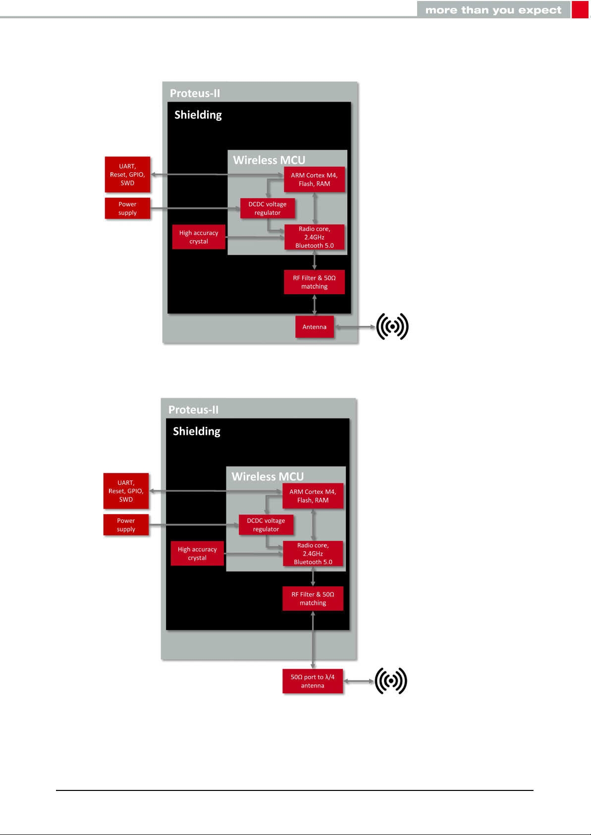
1.2. Block diagram
Figure 1: Block diagram of the module with internal PCB antenna and antenna pad
Proteus-II reference manual version 1.10 © December 2020
www.we-online.com/wireless-connectivity 12
Page 14

1.3. Ordering information
WE order code Former order code Description
2608011024010 AMB2623-TR
2608011124010 AMB2623-1-TR Bluetooth®Smart Module with RF pad, Tape & Reel
2608011024019 AMB2623-DEV Development Kit including 3×AMB2623
2608011124019 AMB2623-1-DEV Development Kit including 3×AMB2623-1
Table 1: Ordering information
Bluetooth®Smart Module with integrated antenna,
Tape & Reel
Proteus-II reference manual version 1.10 © December 2020
www.we-online.com/wireless-connectivity 13
Page 15
2. Electrical specifications
As not otherwise stated measured on the evaluation board Proteus-II-EV with T=25°C,
VDDS=3V, f=2.44GHz, internal DC-DC converter in use.
2.1. Recommended operating conditions
Description Min. Typ. Max. Unit
Ambient temperature -40 25 85 °C
Supply voltage (VDDS) 1.8 3 3.6 V
Supply rise time (0V to ≥ 1.7V) 60 ms
Table 2: Recommended operating conditions
The on-chip power-on reset circuitry may not function properly for rise times
longer than the specified maximum.
A step in supply voltage of 300 mV or more, with rise time of 300 ms or less,
within the valid supply range, may result in a system reset.
An instable supply voltage may significantly decrease the radio performance
and stability.
2.2. Absolute maximum ratings
Description Min. Typ. Max. Unit
Supply voltage (VDD) -0.3 +3.9 V
Voltage on any digital pin, VDD≤3.6V -0.3 VDD+0.3 V
Voltage on any digital pin, VDD≥3.6V -0.3 3.9 V
Input RF level 10 dBm
Flash endurance 10 000 Write/erase cycles
Table 3: Absolute maximum ratings
Proteus-II reference manual version 1.10 © December 2020
www.we-online.com/wireless-connectivity 14
Page 16

2.3. Power consumption
2.3.1. Static
Continuous test mode
TX current consumption at +4 dBm
TX current consumption at 0 dBm
RX current consumption
Sleep (system off mode)
TX current consumption at +4 dBm
TX current consumption at 0 dBm
RX current consumption
Min. Typ. Max. Unit
1
7.5
5.3
5.4
1
1
mA
mA
mA
0.4 µA
2
11
8
8
2
2
mA
mA
mA
Table 4: Power consumption for 100% transmission/reception
Due to the Bluetooth®LE time slot operation, the real operating currents are
reduced significantly and depend on the user selectable advertising and connection interval settings.
1
Transmitter only with DC/DC converter from nRF52 data sheet.
2
Full module power consumption.
Proteus-II reference manual version 1.10 © December 2020
www.we-online.com/wireless-connectivity 15
Page 17
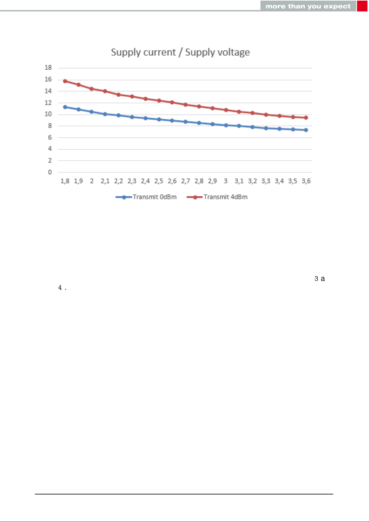
Figure 2: TX Current consumption vs. VCC
2.3.2. Dynamic
Besides the static TX, RX, idle and sleep current the average current is of interest. Here an
example for a typical behavior of a peripheral device in advertising mode (see Figure3and
Figure4). Currents and state durations are dependent on the configuration of the module.
In this state the module transmits the advertising packets on the 3 advertising channels.
Nordic Semiconductor provides an online tool calculating the average current of a Bluetooth
connection. It can be accessed at https://devzone.nordicsemi.com/power/ .
®
Proteus-II reference manual version 1.10 © December 2020
www.we-online.com/wireless-connectivity 16
Page 18
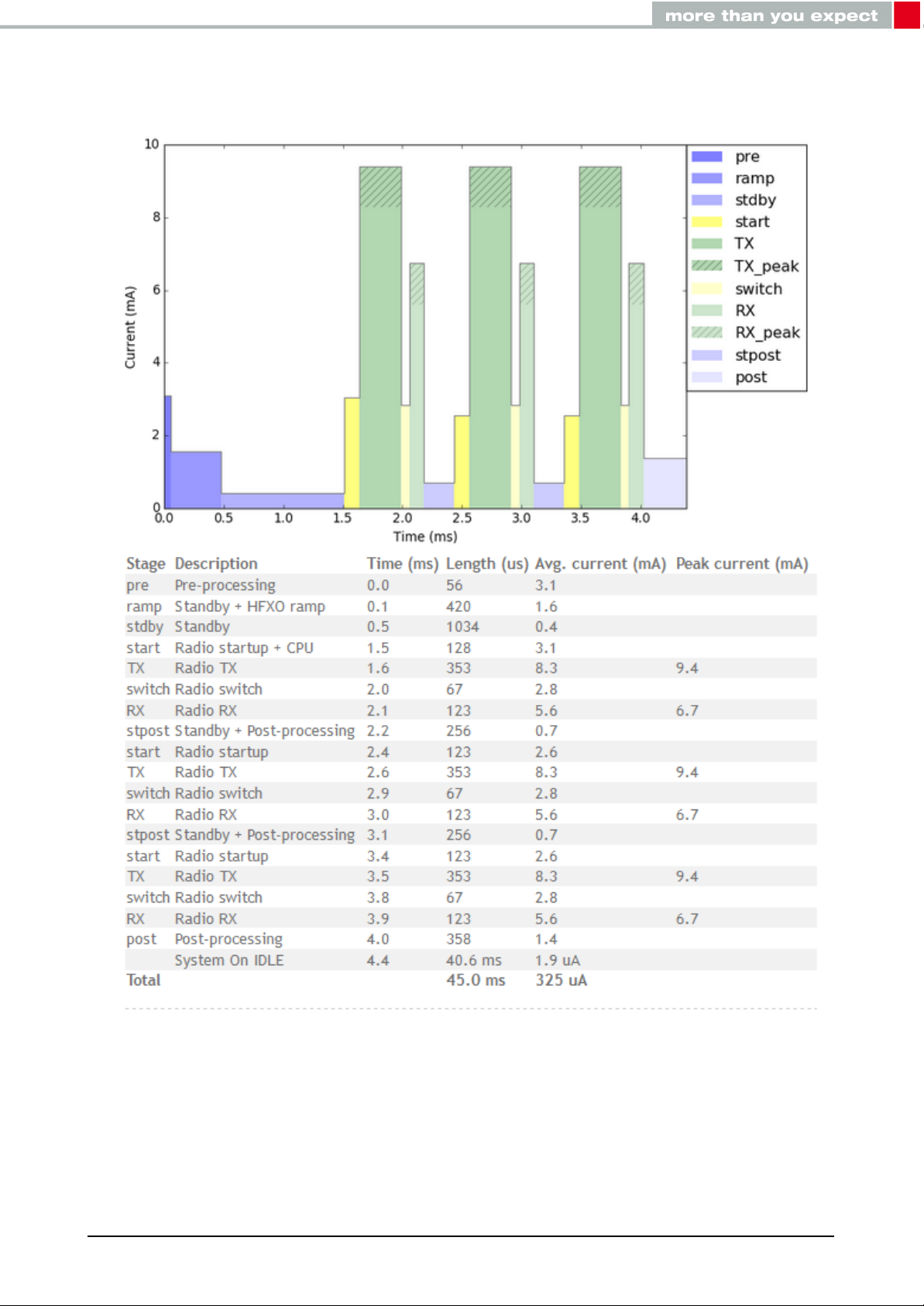
Figure 3: Current consumption calculation in advertising mode with 40ms advertising inter-
val, UART disabled
Proteus-II reference manual version 1.10 © December 2020
www.we-online.com/wireless-connectivity 17
Page 19
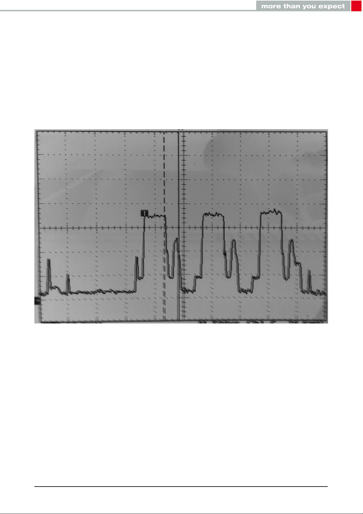
Figure 4: Measured Proteus-II transient current consumption in advertising mode with 40ms
advertising interval, excerpt of 5ms
Proteus-II reference manual version 1.10 © December 2020
www.we-online.com/wireless-connectivity 18
Page 20
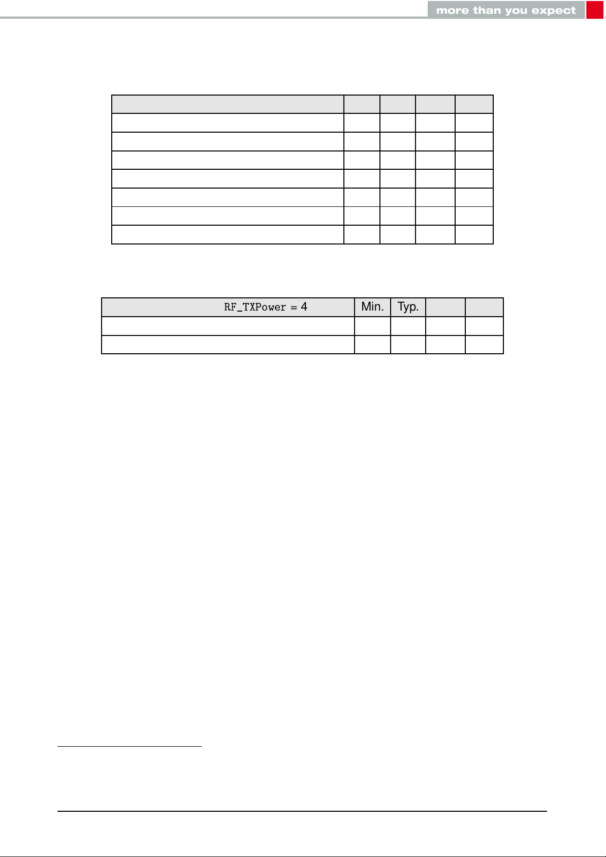
2.4. Radio characteristics
50Ω conducted measurements from nRF52 data sheet
Description Min. Typ. Max. Unit
Output power -40 +3 +4 dBm
Input sensitivity (≤ 37 Bytes, BER=1E-3) -92
RSSI accuracy valid range (±2dB) -90 -20 dBm
Enable TX or RX delay 140 µs
Enable TX or RX delay (fast mode) 40 µs
Disable TX delay 6 µs
Disable RX delay 0 µs
Table 5: Radio parameters
1
dBm
Output power
RF_TXPower
= 4 Min. Typ. Max. Unit
Proteus-II external antenna (50Ω conducted) 3 4 dBm
Proteus-II integrated pcb antenna (e.i.r.p.) -2 0 dBm
Table 6: Output power
1
nRF52832 Rev.1, with build code CIAA-B00, CSP package, in DC/DC Mode
Proteus-II reference manual version 1.10 © December 2020
www.we-online.com/wireless-connectivity 19
Page 21

2.5. Pin characteristics
Measurements from nRF52 data sheet
Description
Input high voltage
Input low voltage
Current at VSS+0.4 V, output set low, standard
drive, VDD ≥1.7V
Current at VSS+0.4 V, output set low, high drive,
VDD ≥ 2.7 V
Current at VSS+0.4 V, output set low, high drive,
VDD ≥ 1.7 V
Current at VDD-0.4 V, output set high, standard
drive, VCC ≥1.7V
Current at VDD-0.4 V, output set high, high
drive, VDD ≥ 2.7 V
Current at VDD-0.4 V, output set high, high
drive, VDD ≥ 1.7 V
Internal pull-up resistance
Internal pull-down resistance
Min. Typ. Max. Unit
0.7 ×VCC VCC V
VSS 0.3 ×VCC V
1 2 4 mA
6 10 15 mA
3 mA
1 2 4 mA
6 9 14 mA
3 mA
13 kΩ
13 kΩ
Table 7: Pin characteristics
Proteus-II reference manual version 1.10 © December 2020
www.we-online.com/wireless-connectivity 20
Page 22
3. Pinout
GND
WAKE_UP
/CTS
/RTS
LED_2
LED_1
URXD
UTXD
OP_MODE
VDD
BOOT
/RESET
SWDIO
SWDCLK
ANT
17
12
11
8
7
1
GND
RESERVED
Figure 5: Pinout (top view)
Proteus-II reference manual version 1.10 © December 2020
www.we-online.com/wireless-connectivity 21
Page 23

No µC Pin Designation I/O Description
Antenna connection in case of module variant
1 ANT RF
with external antenna. In case of module with
integrated antenna, do not connect.
2 GND Supply Ground
3 SWDCLK Input
4 SWDIO Input
5 P0.21 /RESET Input
Serial wire clock. Uses internal pull down resistor. Do not connect if not needed.
Serial wire input/output. Uses internal pull up resistor. Do not connect if not needed.
Reset pin. A low signal resets the module. Uses
internal pull up resistor.
Boot pin. A low signal during and short after re-
6 P0.05/AIN3 BOOT Input
set starts the module in OTA bootloader mode.
Uses internal pull up resistor1. Do not connect if
not needed.
7 VDD Supply Supply voltage
Operation mode pin with internal pull down resis-
8 P0.10/NFC22OP_MODE Input
tor1during start-up. Low level or open: Normal
Mode. High level: Peripheral only Mode. Do not
connect if not needed.
9 P0.09/NFC12RESERVED I/O Do not connect.
10 P0.00/XL1
3
LED_1 Output
Indicates the module state (active high). Do not
connect if not needed.
11 P0.01/XL2
3
LED_2 Output
Indicates the module state (active high). Do not
connect if not needed.
12 P0.02/AIN0 UTXD Output UART(Transmission)
13 P0.03/AIN1 URXD Input
14 P0.04/AIN2 /RTS Output
15 P0.28/AIN4 /CTS Input
UART (Reception). Uses internal pull up resistor1.
Only used if flow control is enabled. Do not connect if not needed.
Only used if flow control is enabled. Do not connect if not needed.
Wake-up will allow leaving the system-off mode
16 P0.29/AIN5 WAKE_UP Input
or re-enabling the UART. Uses internal pull up
resistor1. Do not connect if not needed.
17 GND Supply Ground
Table 8: Pinout
1
Internal pull ups or pull downs are configured at startup by the firmware installed in the SoC. The pull up on
the /RESET pin cannot be disabled by firmware.
2
NFC pins available for NFC function in custom firmware. The standard firmware of Proteus-II does not
implement this function.
3
Pins available to connect an external crystal in custom firmware. The standard firmware of Proteus-II does
Proteus-II reference manual version 1.10 © December 2020
www.we-online.com/wireless-connectivity 22
Page 24

not implement this function.
Proteus-II reference manual version 1.10 © December 2020
www.we-online.com/wireless-connectivity 23
Page 25
4. Quick start
4.1. Minimal pin configuration
In factory state the modules are immediately ready for operation; the following pins are required in the minimal configuration:
VDD, GND, UTXD, URXD, /RESET
If the flow control is enabled additionally the pins /RTS and /CTS shall be connected.
We recommend to additionally have the pins SWDIO and SWDCLK accessible in order to
support a fail-safe firmware update. A standard socket on the customer’s PCB for connecting a flash adapter can be useful for debugging purposes (e.g. a JTAG 2*10 pin header with
2.54mm pin-to-pin distance).
Implementing the fail-safe firmware update method using the SWD interface is
recommended. Without having the SWD interface available a fail-safe firmware
update on a customer PCB cannot be guaranteed.
If the module has to be connected to a PC, a converter (TTL to RS-232 or TTL to USB) has
to be used. See chapter3for details on all pins. Please refer to the Proteus-II-EV schemes
for a reference design.
The logic level of the module is based on 3V. A 5V logic level must not be
connected directly to the module.
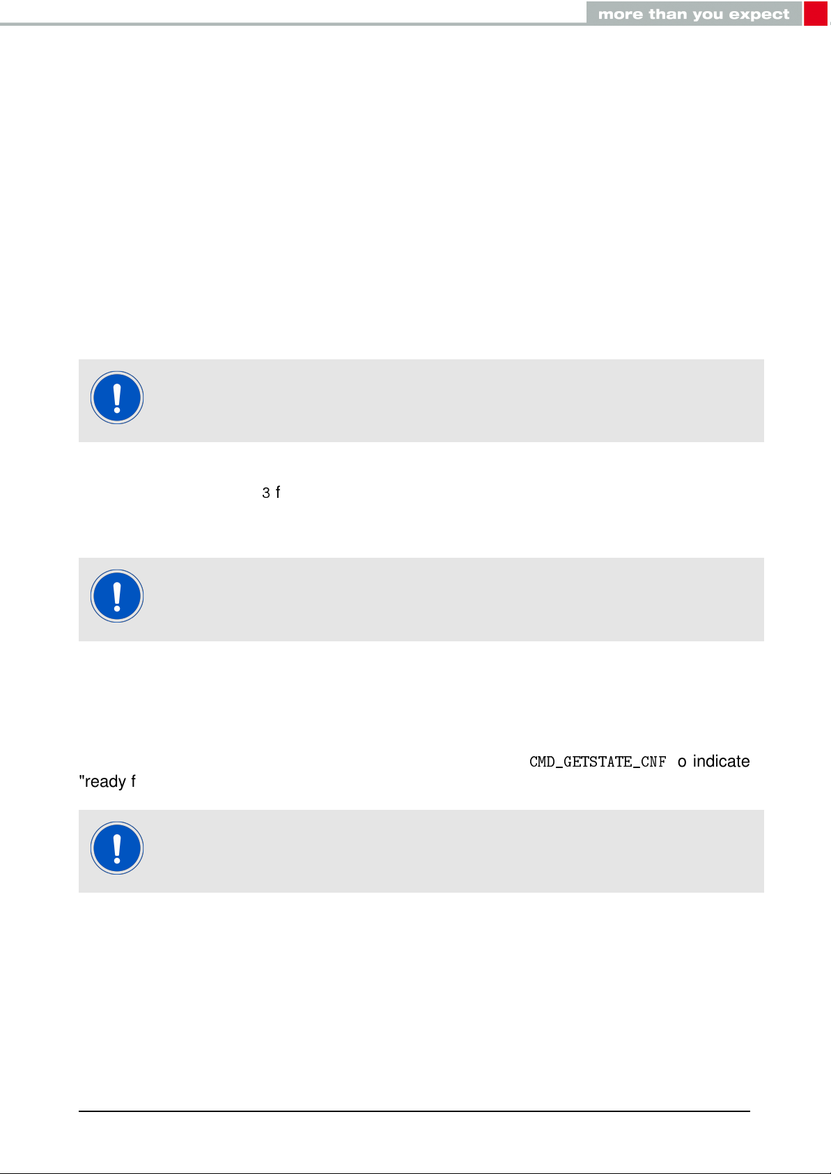
4.2. Power up
After powering the module the /RESET pin shall be hold for another ∆t of 1ms after the VDD
is stable to ensure a safe start-up. The module will send a
"ready for operation" after the /RESET pin was released.
Applying a reset (e.g. a host temporarily pulling the /RESET pin down for at
least 1ms and releasing it again) after the VCC is stable will also be sufficient.
CMD_GETSTATE_CNF
to indicate
Proteus-II reference manual version 1.10 © December 2020
www.we-online.com/wireless-connectivity 24
Page 26
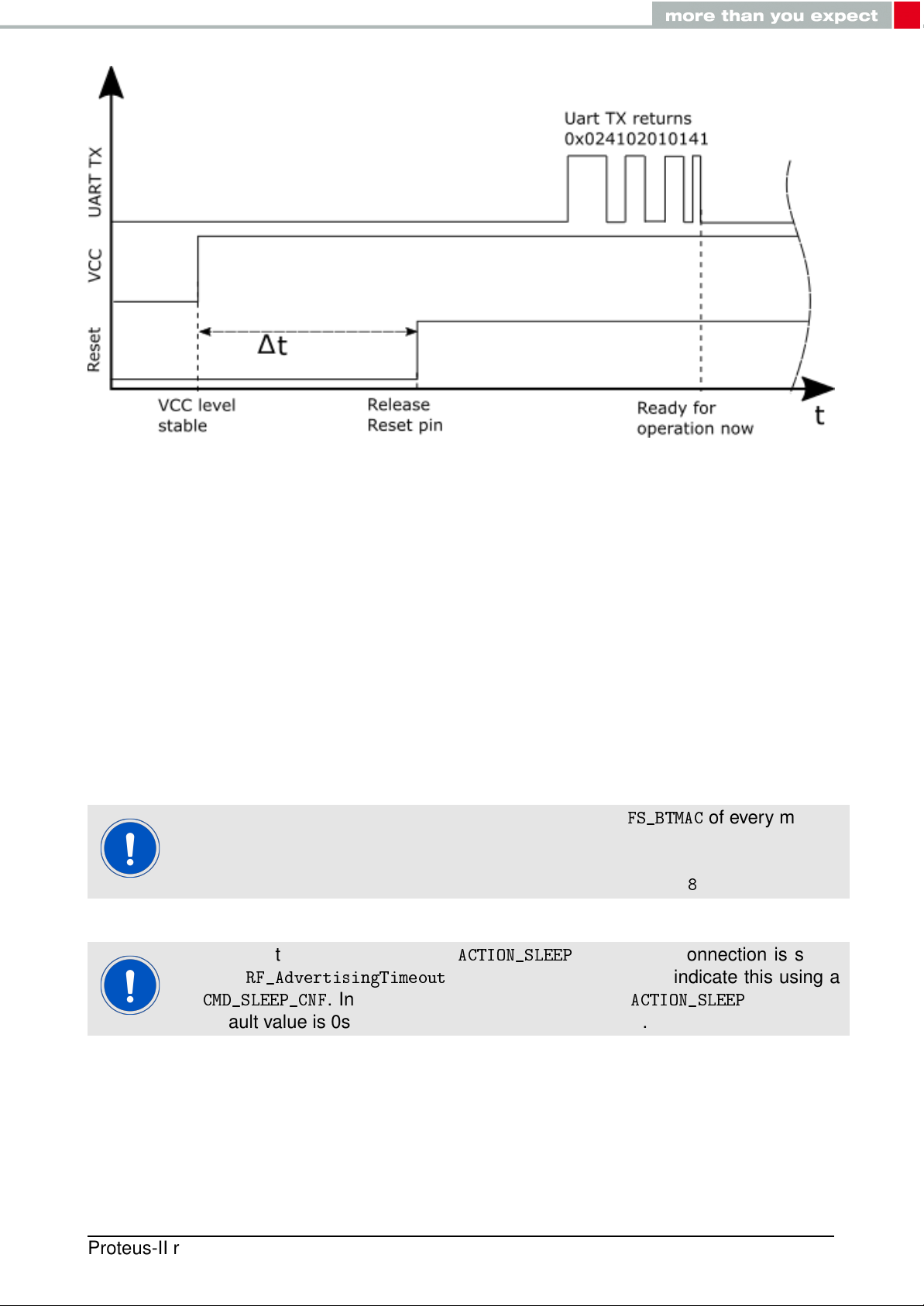
Figure 6: Power up
4.3. Quickstart example
This section describes how to quick start the data transmission between two Proteus-II modules. The goal is to setup a connection between module A and module B, transmit some
data and close the connection again.
In this section, all packet data from or to the modules is given in hexadecimal notation. For
quick testing, a pair of Proteus-II-EV is recommended.
Connect the two devices (modules, EV-boards or USB dongles) to a PC. A terminal program, for example hterm, is used to perform the communication via COM ports. The two
corresponding COM ports have to be selected and opened with a default configuration of
115200 Baud, 8 data Bits, 1 stop Bit and parity set to none (8n1).
To reproduce the following sequence, note that, the
is different, thus it has to be replaced it in the commands below. In addition, the
checksum has to be adjusted, when adapting any command. The command
structure and checksum calculation is described in chapter8.
Note that the module goes to
after
RF_AdvertisingTimeout
CMD_SLEEP_CNF
default value is 0s, which means that it will run forever.
Proteus-II reference manual version 1.10 © December 2020
www.we-online.com/wireless-connectivity 25
. In addition, the UART is disabled in
ACTION_SLEEP
seconds. The module will indicate this using a
mode if no connection is setup
FS_BTMAC
ACTION_SLEEP
of every module
mode. The
Page 27
Connection setup and first data transmission
1. Power-up the modules and make their UARTs accessible by the host(s) (115200 Baud,
8n1). After the power-up or after reset the following sequence is sent from the module.
Info Module A Module B
⇐ Response
started in
⇐ Response
started in
2. Request the
Info Module A Module B
⇒ Request
⇐ Response
module A is 0x55 0x00 0x00 0xDA 0x18 0x00
⇒ Request
⇐ Response
module B is 0x11 0x00 0x00 0xDA 0x18 0x00
3. Connect module A to module B via Bluetooth®.
CMD_GETSTATE_CNF
ACTION_IDLE
CMD_GETSTATE_CNF
ACTION_IDLE
FS_BTMAC
CMD_GET_REQ
CMD_GET_CNF:FS_BTMAC
CMD_GET_REQ
CMD_GET_CNF:FS_BTMAC
mode.
mode.
of both modules.
with settings index 4 02 10 01 00 04 17
with settings index 4 02 10 01 00 04 17
: Module A
: Module B
of
of
02 41 02 00 01 01 41
02 41 02 00 01 01 41
02 50 07 00 00 55 00
00 DA 18 00 C2
02 50 07 00 00 11 00
00 DA 18 00 86
This example is taken from an older firmware. Using newer firmwares with the
optional Bluetooth®4.2 feature "LE Packet Length Extension", the maximum
supported payload per packet may be higher than 0x13.
Proteus-II reference manual version 1.10 © December 2020
www.we-online.com/wireless-connectivity 26
Page 28
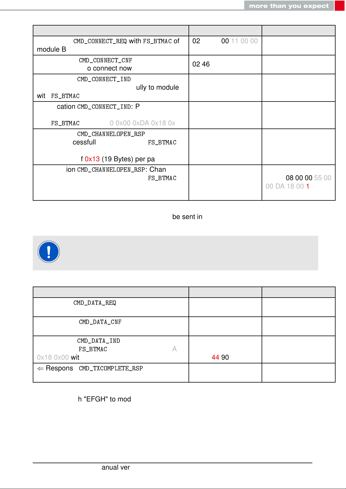
Info Module A Module B
⇒ Request
module B
⇐ Response
understood, try to connect now
⇐ Indication
connection established successfully to module
with
FS_BTMAC
⇐ Indication
connection established successfully to module
with
FS_BTMAC
⇐ Indication
opened successfully to module with
0x11 0x00 0x00 0xDA 0x18 0x00 and maximum
payload size of 0x13 (19 Bytes) per packet
⇐ Indication
opened successfully to module with
0x55 0x00 0x00 0xDA 0x18 0x00 and maximum
payload size of 0x13 (19 Bytes) per packet
CMD_CONNECT_REQ
CMD_CONNECT_CNF
CMD_CONNECT_IND
0x11 0x00 0x00 0xDA 0x18 0x00
CMD_CONNECT_IND
0x55 0x00 0x00 0xDA 0x18 0x00
CMD_CHANNELOPEN_RSP
CMD_CHANNELOPEN_RSP
with
FS_BTMAC
: Request
: Physical
: Physical
: Channel
FS_BTMAC
: Channel
FS_BTMAC
of
02 06 06 00 11 00 00
DA 18 00 D1
02 46 01 00 00 45
02 86 07 00 00 11 00
00 DA 18 00 50
02 86 07 00 00 55 00
00 DA 18 00 14
02 C6 08 00 00 11 00
00 DA 18 00 13 C3
02 C6 08 00 00 55 00
00 DA 18 00 13 87
4. Once the connection is active, data can be sent in each direction. Let us send a string
"ABCD" from module B to module A.
The RSSI values will be different in your tests.
Info Module A Module B
⇒ Request
module A
⇐ Response
send data now
⇐ Indication
"ABCD" from
0x18 0x00 with RSSI of 0xCA (-54dBm)
⇐ Response
transmitted successfully
CMD_DATA_REQ
CMD_DATA_CNF
CMD_DATA_IND
FS_BTMAC
CMD_TXCOMPLETE_RSP
: Send "ABCD" to
: Request received,
: Received string
0x11 0x00 0x00 0xDA
: Data
02 04 04 00 41 42 43
44 06
02 44 01 00 00 47
02 84 0B 00 11 00
00 DA 18 00 CA 41
42 43 44 90
02 C4 01 00 00 C7
5. Reply with "EFGH" to module B.
Proteus-II reference manual version 1.10 © December 2020
www.we-online.com/wireless-connectivity 27
Page 29
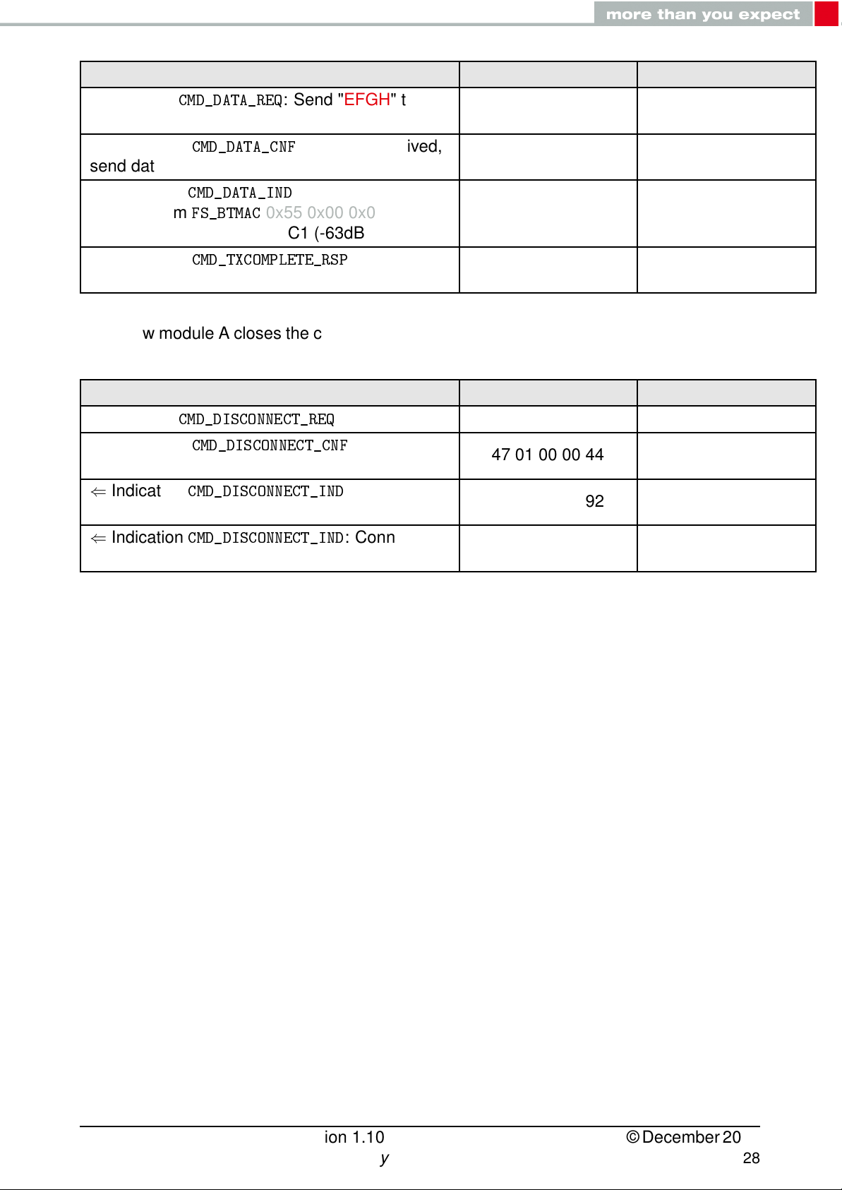
Info Module A Module B
⇒ Request
module B
⇐ Response
send data now
⇐ Indication
"EFGH" from
0x18 0x00 with RSSI of 0xC1 (-63dBm)
⇐ Response
transmitted successfully
6. Now module A closes the connection, so both modules will get a disconnect indication.
Info Module A Module B
⇒ Request
⇐ Response
received, disconnect now
⇐ Indication
closed
CMD_DATA_REQ
CMD_DATA_CNF
CMD_DATA_IND
FS_BTMAC
CMD_TXCOMPLETE_RSP
CMD_DISCONNECT_REQ
CMD_DISCONNECT_CNF
CMD_DISCONNECT_IND
: Send "EFGH" to
: Request received,
: Received string
0x55 0x00 0x00 0xDA
02 04 04 00 45 46 47
48 0E
02 44 01 00 00 47
: Data
: Disconnect 02 07 00 00 05
: Request
: Connection
02 C4 01 00 00 C7
02 47 01 00 00 44
02 87 01 00 16 92
02 84 0B 00 55 00
00 DA 18 00 C1 45
46 47 48 D7
⇐ Indication
closed
CMD_DISCONNECT_IND
: Connection
02 87 01 00 13 97
Proteus-II reference manual version 1.10 © December 2020
www.we-online.com/wireless-connectivity 28
Page 30
5. Functional description
The Proteus-II module acts as a slave and can be fully controlled by an external host that
implements the command interface. The configuration as well as the operation of the module can be managed by predefined commands that are sent as telegrams over the UART
interface of the module.
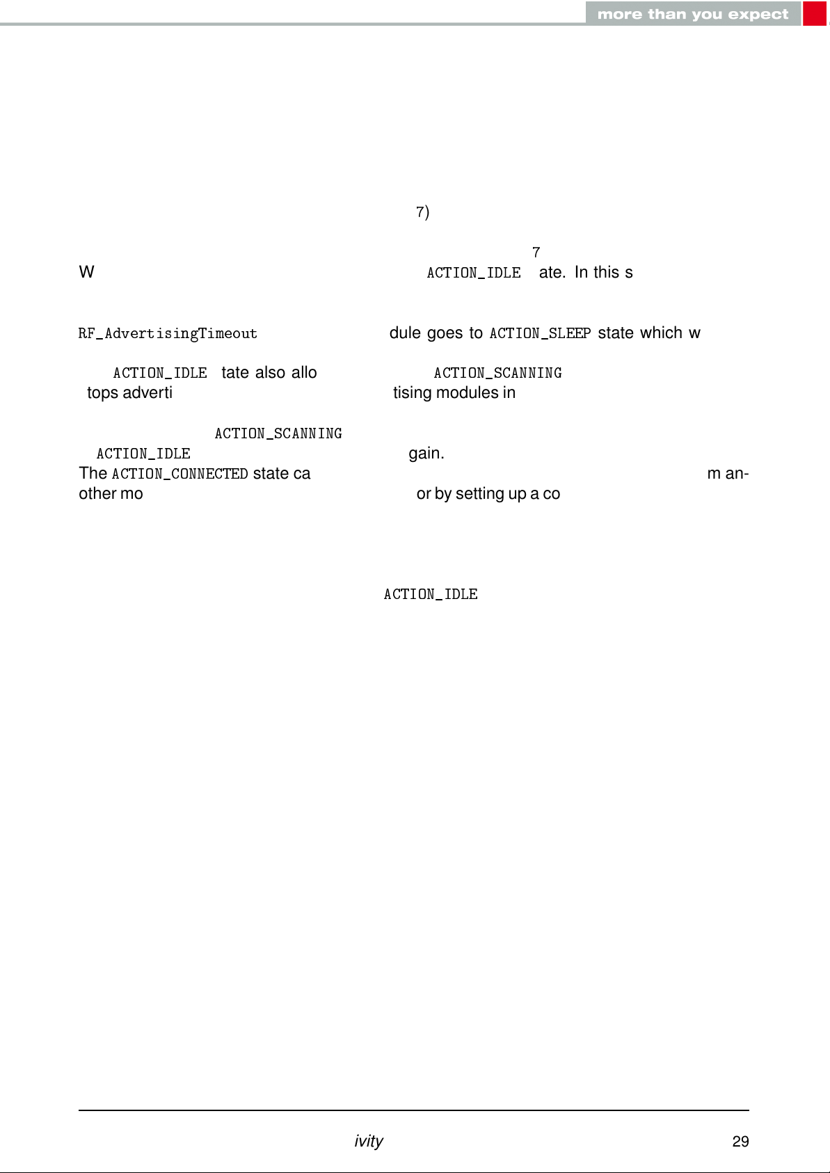
The Proteus-II can operate in different states. Depending on the active state several commands of the command interface (see chapter7) are permitted to modify the state, configure
the module or transmit data over the radio interface. An overview of the different states and
the corresponding allowed commands can be found in Figure7.
When the Proteus-II is powered up, it starts in
advertises (Bluetooth®LE role "peripheral"), such that other devices in range (Bluetooth®LE
role "central" or "observer") can detect it and connect to it. If no connection was setup after
RF_AdvertisingTimeout
advertising.
The
ACTION_IDLE
stops advertising and scans for other advertising modules in range (Bluetooth®LE role "central").
When leaving the
in
ACTION_IDLE
The
ACTION_CONNECTED
other module (Bluetooth®LE role "peripheral") or by setting up a connection itself (Bluetooth®LE
role "central"). In this case it stops advertising and data can be transmitted and received
to/from the connected module. This state remains active as long as the module does not
disconnect itself (e.g. due to a timeout), no disconnection request from the connected device
is received.
When disconnecting, the module goes to
state also allows to switch to
ACTION_SCANNING
state and starts advertising again.
seconds, the module goes to
state with the corresponding command, the module is
state can be entered either by getting a connection request from an-
ACTION_IDLE
ACTION_IDLE
ACTION_SCANNING
state and starts advertising again.
state. In this state the module
ACTION_SLEEP
state which will stop
state, where the module
Proteus-II reference manual version 1.10 © December 2020
www.we-online.com/wireless-connectivity 29
Page 31

Figure 7: State overview
Proteus-II reference manual version 1.10 © December 2020
www.we-online.com/wireless-connectivity 30
Page 32

5.1. State indication using the LED pins
The pins LED_1 and LED_2 of the Proteus-II can be used to determine the module state.
The states described in Figure7result in the following pin behavior. The pins on the ProteusII are active high.
State LED_1 LED_2
ACTION_IDLE
ACTION_SCANNING
ACTION_CONNECTED
ACTION_SLEEP
ACTION_DTM
BOOTLOADER
connection
BOOTLOADER
firmware update running
waiting for
connected,
5.2. Sleep mode
Blinking (On for 200ms, Off for
2800ms)
Blinking (On for 1000ms, Off for
1000ms)
On
Off Off
Off Off
On Off
Off On
Table 9: LED behavior of the Proteus-II
Off
Off
Off, On (as soon as the channel
was opened successfully, see
CMD_CHANNELOPEN_RSP
)
Especially for battery-powered devices the
very low power consumption (<1µA). It can be entered by sending the command
REQ
to the module. If allowed (due to the current operating state) the module will then send
a
CMD_SLEEP_CNF
In
ACTION_SLEEP
data. To prevent leakage current, the host shall not pull the UART_RX to LOW level (as the
module has an internal pull-up resistor enabled on this pin).
To leave the
woken up by applying a low signal to the WAKE_UP pin for at least 5ms before releasing the
signal back to high. The module then restarts completely, so that all volatile settings are set
to default. A
and then enter the
mode the UART is disabled, so the module will not receive or transmit any
ACTION_SLEEP
CMD_GETSTATE_CNF
Please note that the WAKE_UP pin has a second function. If the module is not in
CMD_UARTDISABLE_REQ
holding the line low for at least 10ms before applying a rising edge and
holding it high for at least 10ms. In this case the module answers with a
CMD_UARTENABLE_IND
mode and enter
ACTION_SLEEP
ACTION_SLEEP
will be send when the module is ready for operation.
, the UART can be re-enabled by applying falling edge,
message.
ACTION_SLEEP
mode.
ACTION_IDLE
mode and the UART was disabled using the
mode (system-off mode) supports
CMD_SLEEP_
state again, the module has to be
Proteus-II reference manual version 1.10 © December 2020
www.we-online.com/wireless-connectivity 31
Page 33

5.3. Identification of a Proteus-II device on the radio
The Proteus-II can be identified on the radio interface by its
Bluetooth®-conform MAC address, which is part of the data package sent during advertising
in
ACTION_IDLE
In
ACTION_SCANNING
in range and stores their
connection to the corresponding device can then be established using the
command.
To simplify the identification of Proteus-II devices on the RF-interface a short user-defined
name (see
packet.
mode. A
state a module listens to the data packets of all advertising modules
RF_DeviceName
The
FS_BTMAC
SerialNumber
FS_BTMAC
FS_BTMAC
) can be given to the module, which is also part of the advertising
of the module.
has the size of 6 Bytes.
to an internal data base. With help of a
consists of the company ID 0x0018DA followed by the
FS_BTMAC
. This
FS_BTMAC
FS_BTMAC
CMD_CONNECT_REQ
is a
FS_
5.4. Connection based data transmission, with or without security
In the Bluetooth®LE standard the transmission of data typically is connection based. A connection between two devices can be secured (with or without key exchange) or unsecured
(default setting). In any case, each data packet transmitted is acknowledged on the link layer, such that it is resent as long as a packet is lost. The following lines describe how to run
the connection setup and data transmission using the Proteus-II.
If module A is supposed to setup a connection with module B, module A can use the command
unknown, a scan can be run before by module A to discover all available modules in range.
After sending the command
to signal that the request has been understood and the module now tries to establish the
connection.
If module B cannot be found on the air within a timeout, module A outputs a
with "failed" as status. Otherwise, as soon as the physical connection has been set up successfully, module A and B print a
tion and LED_1 turns on.
Next some security and authentication messages will follow, like
rity is enabled.
After the physical connection has been setup successfully the modules exchange their services. As soon as this has finished successfully, a
UART indicating that the connection is ready for data transmission. Furthermore, LED_2
turns on.
Now data can be transmitted in both directions using the command
confirmed by a
transmitted successfully).
Each time data has been received a
data.
As soon as one module closes the connection using a
will inform their host by a
CMD_CONNECT_REQ
CMD_DATA_CNF
including the
CMD_CONNECT_REQ
(data will be processed) and a
CMD_DISCONNECT_IND
FS_BTMAC
CMD_CONNECT_IND
CMD_DATA_IND
of module B. If the
, the module answers with a
with the status of the successful connec-
CMD_CHANNELOPEN_RSP
will be output containing the transmitted
CMD_DISCONNECT_REQ
message that the connection is no longer
FS_BTMAC
CMD_SECURITY_IND
CMD_DATA_REQ
CMD_TXCOMPLETE_RSP
of module B is
CMD_CONNECT_CNF
CMD_CONNECT_IND
, if secu-
is given out to the
, both modules
. It is
(data
a
Proteus-II reference manual version 1.10 © December 2020
www.we-online.com/wireless-connectivity 32
Page 34

open. If one module is no longer within range, the
gered by a timeout.
For an example on setting up an unsecured connection, see chapter
Proteus-II application note "advanced user guide" to get detailed information about the connection setup with foreign devices.
5.4.1. Further information for a secure connection setup
The
RF_SecFlags
curity mode of a Proteus-II peripheral device is set, its security level has to be met by the
connecting central device to be able to exchange data. As soon as the defined security level
is not met by the central device, no access to the peripheral’s profiles will be granted.
parameter of the module determines the security mode. If a certain se-
When connecting from a Proteus-II to a Proteus-II, you shall not use different
security modes.
To get further information about the secured connection setup, when using a
foreign device (i.e. mobile phone with a custom APP), please refer to the Application Note "advanced user guide" (Proteus-I: ANR002, Proteus-II: ANR005).
CMD_DISCONNECT_IND
4.3
message is trig-
. See also the
5.4.1.1. Just works mode
In case of the "Just works" mode, each time a connection is established, a new random key
is exchanged in advance to be used for data encryption. Since no authentication will be
performed, also devices without input and output capabilities (like keyboard or display) are
able to connect to each other.
Example: Secured connection with LE Legacy security method "Just Works" without
bonding
1. Power-up the modules and make their UARTs accessible by the host(s) (115200 Baud,
8n1). After the power-up or after reset the following sequence is sent from the module
Info Module A Module B
⇐ Response
started in
⇐ Response
started in
CMD_GETSTATE_CNF
ACTION_IDLE
CMD_GETSTATE_CNF
ACTION_IDLE
mode.
mode.
: Module A
: Module B
02 41 02 00 01 01 41
02 41 02 00 01 01 41
2. Request the
Proteus-II reference manual version 1.10 © December 2020
www.we-online.com/wireless-connectivity 33
FS_BTMAC
of both modules.
Page 35

Info Module A Module B
⇒ Request
⇐ Response
module A is 0x55 0x00 0x00 0xDA 0x18 0x00
⇒ Request
⇐ Response
module B is 0x11 0x00 0x00 0xDA 0x18 0x00
3. Configure the parameter
CMD_GET_REQ
with settings index 4 02 10 01 00 04 17
CMD_GET_CNF:FS_BTMAC
CMD_GET_REQ
with settings index 4 02 10 01 00 04 17
CMD_GET_CNF:FS_BTMAC
RF_SecFlags
of
02 50 07 00 00 55 00
00 DA 18 00 C2
of
02 50 07 00 00 11 00
00 DA 18 00 86
to use "Just Works" pairing method for Bluetooth
security.
Info Module A Module B
⇒Perform
and value 0x02 on module A
⇐ Response
to adopt the new value)
⇐ Response
⇒Perform
and value 0x02 on module B
CMD_SET_REQ
with settings index 12
CMD_SET_CNF
CMD_GETSTATE_CNF
CMD_SET_REQ
with settings index 12
(Module will restart
02 11 02 00 0C 02
1F
02 51 01 00 00 52
02 41 02 00 01 01 41
02 11 02 00 0C 02
1F
®
⇐ Response
CMD_SET_CNF
(Module will restart
to adopt the new value)
⇐ Response
CMD_GETSTATE_CNF
4. Connect module A to module B via Bluetooth®.
02 51 01 00 00 52
02 41 02 00 01 01 41
Proteus-II reference manual version 1.10 © December 2020
www.we-online.com/wireless-connectivity 34
Page 36

Info Module A Module B
⇒ Request
module B
⇐ Response
understood, try to connect now
⇐ Indication
connection established successfully to module
with
FS_BTMAC
⇐ Indication
connection established successfully to module
with
FS_BTMAC
⇐ Indication
(encrypted link, pairing, no bonding), with
FS_BTMAC
⇐ Indication
(encrypted link, pairing, no bonding), with
FS_BTMAC
⇐ Indication
opened successfully to module with
0x11 0x00 0x00 0xDA 0x18 0x00 and maximum
payload size of 0xF3 (243 Bytes) per packet
CMD_CONNECT_REQ
CMD_CONNECT_CNF
CMD_CONNECT_IND
0x11 0x00 0x00 0xDA 0x18 0x00
CMD_CONNECT_IND
0x55 0x00 0x00 0xDA 0x18 0x00
CMD_SECURITY_IND
0x11 0x00 0x00 0xDA 0x18 0x00
CMD_SECURITY_IND
0x55 0x00 0x00 0xDA 0x18 0x00
CMD_CHANNELOPEN_RSP
with
FS_BTMAC
: Request
: Physical
: Physical
, status 0x02
, status 0x02
: Channel
FS_BTMAC
of
02 06 06 00 11 00 00
DA 18 00 D1
02 46 01 00 00 45
02 86 07 00 00 11 00
00 DA 18 00 50
02 86 07 00 00 55 00
00 DA 18 00 14
02 88 07 00 02 11 00
00 DA 18 00 5C
02 88 07 00 02 55 00
00 DA 18 00 18
02 C6 08 00 00 11 00
00 DA 18 00 F3 EC
⇐ Indication
opened successfully to module with
0x55 0x00 0x00 0xDA 0x18 0x00 and maximum
payload size of 0xF3 (243 Bytes) per packet
5. Once the connection is active, data can be sent in each direction. Let us send a string
"ABCD" from module B to module A.
CMD_CHANNELOPEN_RSP
The RSSI values will be different in your tests.
: Channel
FS_BTMAC
02 C6 08 00 00 55 00
00 DA 18 00 F3 A8
Proteus-II reference manual version 1.10 © December 2020
www.we-online.com/wireless-connectivity 35
Page 37

Info Module A Module B
⇒ Request
module A
⇐ Response
send data now
⇐ Indication
"ABCD" from
0x18 0x00 with RSSI of 0xCA (-54dBm)
⇐ Response
transmitted successfully
6. Reply with "EFGH" to module B.
Info Module A Module B
⇒ Request
module B
⇐ Response
send data now
⇐ Indication
"EFGH" from
0x18 0x00 with RSSI of 0xC1 (-63dBm)
CMD_DATA_REQ
CMD_DATA_CNF
CMD_DATA_IND
FS_BTMAC
CMD_TXCOMPLETE_RSP
CMD_DATA_REQ
CMD_DATA_CNF
CMD_DATA_IND
FS_BTMAC
: Send "ABCD" to
: Request received,
: Received string
0x11 0x00 0x00 0xDA
: Send "EFGH" to
: Request received,
: Received string
0x55 0x00 0x00 0xDA
: Data
02 04 04 00 41 42 43
44 06
02 44 01 00 00 47
02 84 0B 00 11 00
00 DA 18 00 CA 41
42 43 44 90
02 C4 01 00 00 C7
02 04 04 00 45 46 47
48 0E
02 44 01 00 00 47
02 84 0B 00 55 00
00 DA 18 00 C1 45
46 47 48 D7
⇐ Response
transmitted successfully
7. Now module A closes the connection, so both modules will get a disconnect indication.
Info Module A Module B
⇒ Request
⇐ Response
received, disconnect now
⇐ Indication
closed
⇐ Indication
closed
8. You may want to perform a
CMD_TXCOMPLETE_RSP
CMD_DISCONNECT_REQ
CMD_DISCONNECT_CNF
CMD_DISCONNECT_IND
CMD_DISCONNECT_IND
: Data
: Disconnect 02 07 00 00 05
: Request
: Connection
: Connection
CMD_FACTORYRESET_REQ
02 C4 01 00 00 C7
02 47 01 00 00 44
02 87 01 00 16 92
to restore default settings.
02 87 01 00 13 97
5.4.1.2. StaticPasskey mode
In case of the "StaticPasskey" mode, a pass key has to be entered at the central side that
has to match the pass key of the peripheral. Here the Proteus-II uses a static pass key in the
peripheral role that is stored in the parameter
Proteus-II reference manual version 1.10 © December 2020
www.we-online.com/wireless-connectivity 36
RF_StaticPasskey
. When using this method,
Page 38

the central device requests its host to enter the correct pass key (see
CMD_PASSKEY_IND
In this case the pass key of the peripheral has to be entered on central side using the
CMD_PASSKEY_REQ
command. If the entered pass key is correct, the channel will be opened
for data transmission. Otherwise, the connection will be rejected.
Example: Secured connection with security method "StaticPasskey"
1. Power-up the modules and make their UARTs accessible by the host(s) (115200 Baud,
8n1). After the power-up or after reset the following sequence is sent from the module
Info Module A Module B
).
⇐ Response
started in
⇐ Response
started in
2. Request the
CMD_GETSTATE_CNF
ACTION_IDLE
CMD_GETSTATE_CNF
ACTION_IDLE
FS_BTMAC
: Module A
mode.
: Module B
mode.
of both modules.
02 41 02 00 01 01 41
02 41 02 00 01 01 41
Info Module A Module B
⇒ Request
⇐ Response
module A is 0x55 0x00 0x00 0xDA 0x18 0x00
⇒ Request
⇐ Response
module B is 0x11 0x00 0x00 0xDA 0x18 0x00
3. Configure the parameter
CMD_GET_REQ
with settings index 4 02 10 01 00 04 17
CMD_GET_CNF:FS_BTMAC
CMD_GET_REQ
with settings index 4 02 10 01 00 04 17
CMD_GET_CNF:FS_BTMAC
RF_SecFlags
of
02 50 07 00 00 55 00
00 DA 18 00 C2
of
02 50 07 00 00 11 00
00 DA 18 00 86
to use "StaticPasskey" pairing method for Bluetooth
security.
®
Info Module A Module B
⇒Perform
and value 0x03 on module A
⇐ Response
to adopt the new value)
⇐ Response
⇒Perform
and value 0x03 on module B
⇐ Response
to adopt the new value)
⇐ Response
CMD_SET_REQ
with settings index 12
CMD_SET_CNF
CMD_GETSTATE_CNF
CMD_SET_REQ
with settings index 12
CMD_SET_CNF
CMD_GETSTATE_CNF
(Module will restart
(Module will restart
02 11 02 00 0C 03
1E
02 51 01 00 00 52
02 41 02 00 01 01 41
02 11 02 00 0C 03
1E
02 51 01 00 00 52
02 41 02 00 01 01 41
4. Connect module A to module B via Bluetooth®.
Proteus-II reference manual version 1.10 © December 2020
www.we-online.com/wireless-connectivity 37
Page 39

Info Module A Module B
⇒ Request
module B
⇐ Response
understood, try to connect now
⇐ Indication
connection established successfully to module
with
FS_BTMAC
⇐ Indication
connection established successfully to module
with
FS_BTMAC
⇐ Indication
pass key
⇒ Answer with the
pass key "123123"
⇐ Response
⇐ Indication
(encrypted link, pairing, no bonding), with
FS_BTMAC
CMD_CONNECT_REQ
CMD_CONNECT_CNF
CMD_CONNECT_IND
0x11 0x00 0x00 0xDA 0x18 0x00
CMD_CONNECT_IND
0x55 0x00 0x00 0xDA 0x18 0x00
CMD_PASSKEY_IND
CMD_PASSKEY_REQ
CMD_PASSKEY_CNF
CMD_SECURITY_IND
0x11 0x00 0x00 0xDA 0x18 0x00
with
FS_BTMAC
: Request
: Physical
: Physical
to ask for the
and the
: Pass key ok 02 4D 01 00 00 4E
, status 0x02
of
02 06 06 00 11 00 00
DA 18 00 D1
02 46 01 00 00 45
02 86 07 00 00 11 00
00 DA 18 00 50
02 86 07 00 00 55 00
00 DA 18 00 14
02 8D 07 00 00 11
00 00 DA 18 00 5B
02 0D 06 00 31 32
33 31 32 33 09
02 88 07 00 02 11 00
00 DA 18 00 5C
⇐ Indication
(encrypted link, pairing, no bonding), with
FS_BTMAC
⇐ Indication
opened successfully to module with
0x11 0x00 0x00 0xDA 0x18 0x00 and maximum
payload size of 0xF3 (243 Bytes) per packet
⇐ Indication
opened successfully to module with
0x55 0x00 0x00 0xDA 0x18 0x00 and maximum
payload size of 0xF3 (243 Bytes) per packet
5. Once the connection is active, data can be sent in each direction. Let us send a string
"ABCD" from module B to module A.
CMD_SECURITY_IND
0x55 0x00 0x00 0xDA 0x18 0x00
CMD_CHANNELOPEN_RSP
CMD_CHANNELOPEN_RSP
The RSSI values will be different in your tests.
, status 0x02
: Channel
FS_BTMAC
: Channel
FS_BTMAC
02 C6 08 00 00 11 00
00 DA 18 00 F3 EC
02 88 07 00 02 55 00
00 DA 18 00 18
02 C6 08 00 00 55 00
00 DA 18 00 F3 A8
Proteus-II reference manual version 1.10 © December 2020
www.we-online.com/wireless-connectivity 38
Page 40

Info Module A Module B
⇒ Request
module A
⇐ Response
send data now
⇐ Indication
"ABCD" from
0x18 0x00 with RSSI of 0xCA (-54dBm)
⇐ Response
transmitted successfully
6. Reply with "EFGH" to module B.
Info Module A Module B
⇒ Request
module B
⇐ Response
send data now
⇐ Indication
"EFGH" from
0x18 0x00 with RSSI of 0xC1 (-63dBm)
CMD_DATA_REQ
CMD_DATA_CNF
CMD_DATA_IND
FS_BTMAC
CMD_TXCOMPLETE_RSP
CMD_DATA_REQ
CMD_DATA_CNF
CMD_DATA_IND
FS_BTMAC
: Send "ABCD" to
: Request received,
: Received string
0x11 0x00 0x00 0xDA
: Send "EFGH" to
: Request received,
: Received string
0x55 0x00 0x00 0xDA
: Data
02 04 04 00 41 42 43
44 06
02 44 01 00 00 47
02 84 0B 00 11 00
00 DA 18 00 CA 41
42 43 44 90
02 C4 01 00 00 C7
02 04 04 00 45 46 47
48 0E
02 44 01 00 00 47
02 84 0B 00 55 00
00 DA 18 00 C1 45
46 47 48 D7
⇐ Response
transmitted successfully
7. Now module A closes the connection, so both modules will get a disconnect indication.
Info Module A Module B
⇒ Request
⇐ Response
received, disconnect now
⇐ Indication
closed
⇐ Indication
closed
8. You may want to perform a
CMD_TXCOMPLETE_RSP
CMD_DISCONNECT_REQ
CMD_DISCONNECT_CNF
CMD_DISCONNECT_IND
CMD_DISCONNECT_IND
: Data
: Disconnect 02 07 00 00 05
: Request
: Connection
: Connection
CMD_FACTORYRESET_REQ
02 C4 01 00 00 C7
02 47 01 00 00 44
02 87 01 00 16 92
to restore default settings.
02 87 01 00 13 97
5.4.1.3. Bonding
The
SECFLAGS_BONDING_ENABLE
bonding feature. This feature stores the keys that are exchanged during the pairing phase
Proteus-II reference manual version 1.10 © December 2020
www.we-online.com/wireless-connectivity 39
flag in the
RF_SecFlags
user setting allows enabling the
Page 41

in a connection setup. With this, subsequent connections to bonded devices can be established without renegotiation. Bonding data of up to 32 devices will be stored in the flash.
The commands
certain or all entries of the list of bonded devices.
Example: Secured connection with LE Legacy security method "Just Works" using
bonding
1. Power-up the modules and make their UARTs accessible by the host(s) (115200 Baud,
8n1). After the power-up or after reset the following sequence is sent from the module
Info Module A Module B
CMD_GETBONDS_REQ
and
CMD_DELETEBONDS_REQ
allow to display and remove
⇐ Response
started in
⇐ Response
started in
2. Request the
Info Module A Module B
⇒ Request
⇐ Response
module A is 0x55 0x00 0x00 0xDA 0x18 0x00
⇒ Request
⇐ Response
module B is 0x11 0x00 0x00 0xDA 0x18 0x00
3. Configure the parameter
for Bluetooth®security.
CMD_GETSTATE_CNF
ACTION_IDLE
CMD_GETSTATE_CNF
ACTION_IDLE
FS_BTMAC
CMD_GET_REQ
CMD_GET_CNF:FS_BTMAC
CMD_GET_REQ
CMD_GET_CNF:FS_BTMAC
mode.
mode.
of both modules.
with settings index 4 02 10 01 00 04 17
with settings index 4 02 10 01 00 04 17
: Module A
: Module B
of
of
RF_SecFlags
02 41 02 00 01 01 41
02 41 02 00 01 01 41
02 50 07 00 00 55 00
00 DA 18 00 C2
02 50 07 00 00 11 00
00 DA 18 00 86
to use "Just Works with bonding" pairing method
Proteus-II reference manual version 1.10 © December 2020
www.we-online.com/wireless-connectivity 40
Page 42

Info Module A Module B
⇒Perform
and value 0x0A (Just works with
SECFLAGS_BONDING_ENABLE
module A
⇐ Response
to adopt the new value)
⇐ Response
⇒Perform
and value 0x0A (Just works with
SECFLAGS_BONDING_ENABLE
module B
⇐ Response
to adopt the new value)
⇐ Response
4. Connect module A to module B via Bluetooth®.
Info Module A Module B
CMD_SET_REQ
CMD_SET_CNF
CMD_GETSTATE_CNF
CMD_SET_REQ
CMD_SET_CNF
CMD_GETSTATE_CNF
with settings index 12
with settings index 12
flag set) on
(Module will restart
flag set) on
(Module will restart
02 11 02 00 0C 0A
17
02 51 01 00 00 52
02 41 02 00 01 01 41
02 11 02 00 0C 0A
17
02 51 01 00 00 52
02 41 02 00 01 01 41
⇒ Request
module B
⇐ Response
understood, try to connect now
⇐ Indication
connection established successfully to module
with
FS_BTMAC
⇐ Indication
connection established successfully to module
with
FS_BTMAC
⇐ Indication
(encrypted link, bonding established), with
FS_BTMAC
⇐ Indication
(encrypted link, bonding established), with
FS_BTMAC
⇐ Indication
opened successfully to module with
0x11 0x00 0x00 0xDA 0x18 0x00 and maximum
payload size of 0xF3 (243 Bytes) per packet
CMD_CONNECT_REQ
CMD_CONNECT_CNF
CMD_CONNECT_IND
0x11 0x00 0x00 0xDA 0x18 0x00
CMD_CONNECT_IND
0x55 0x00 0x00 0xDA 0x18 0x00
CMD_SECURITY_IND
0x11 0x00 0x00 0xDA 0x18 0x00
CMD_SECURITY_IND
0x55 0x00 0x00 0xDA 0x18 0x00
CMD_CHANNELOPEN_RSP
with
FS_BTMAC
: Request
: Physical
: Physical
, status 0x01
, status 0x01
: Channel
FS_BTMAC
of
02 06 06 00 11 00 00
DA 18 00 D1
02 46 01 00 00 45
02 86 07 00 00 11 00
00 DA 18 00 50
02 86 07 00 00 55 00
00 DA 18 00 14
02 88 07 00 01 11 00
00 DA 18 00 5F
02 88 07 00 01 55 00
00 DA 18 00 1B
02 C6 08 00 00 11 00
00 DA 18 00 F3 EC
⇐ Indication
opened successfully to module with
0x55 0x00 0x00 0xDA 0x18 0x00 and maximum
payload size of 0xF3 (243 Bytes) per packet
Proteus-II reference manual version 1.10 © December 2020
www.we-online.com/wireless-connectivity 41
CMD_CHANNELOPEN_RSP
: Channel
FS_BTMAC
02 C6 08 00 00 55 00
00 DA 18 00 F3 A8
Page 43

5. Now module A closes the connection, so both modules will get a disconnect indication.
Info Module A Module B
⇒ Request
⇐ Response
received, disconnect now
⇐ Indication
closed
⇐ Indication
closed
6. Connect module A to module B a second time. Now, since both devices have been
bonded before, the exchanged keys are reused.
Info Module A Module B
⇒ Request
module B
⇐ Response
understood, try to connect now
⇐ Indication
connection established successfully to module
with
FS_BTMAC
CMD_DISCONNECT_REQ
CMD_DISCONNECT_CNF
CMD_DISCONNECT_IND
CMD_DISCONNECT_IND
CMD_CONNECT_REQ
CMD_CONNECT_CNF
CMD_CONNECT_IND
0x11 0x00 0x00 0xDA 0x18 0x00
: Disconnect 02 07 00 00 05
: Request
: Connection
: Connection
with
FS_BTMAC
: Request
: Physical
of
02 47 01 00 00 44
02 87 01 00 16 92
02 87 01 00 13 97
02 06 06 00 11 00 00
DA 18 00 D1
02 46 01 00 00 45
02 86 07 00 00 11 00
00 DA 18 00 50
⇐ Indication
connection established successfully to module
with
FS_BTMAC
⇐ Indication
(encrypted link to bonded device), with
FS_BTMAC
⇐ Indication
(encrypted link to bonded device), with
FS_BTMAC
⇐ Indication
opened successfully to module with
0x11 0x00 0x00 0xDA 0x18 0x00 and maximum
payload size of 0xF3 (243 Bytes) per packet
⇐ Indication
opened successfully to module with
0x55 0x00 0x00 0xDA 0x18 0x00 and maximum
payload size of 0xF3 (243 Bytes) per packet
7. You may want to perform a
CMD_CONNECT_IND
0x55 0x00 0x00 0xDA 0x18 0x00
CMD_SECURITY_IND
0x11 0x00 0x00 0xDA 0x18 0x00
CMD_SECURITY_IND
0x55 0x00 0x00 0xDA 0x18 0x00
CMD_CHANNELOPEN_RSP
CMD_CHANNELOPEN_RSP
: Physical
, status 0x00
, status 0x00
: Channel
FS_BTMAC
: Channel
FS_BTMAC
CMD_FACTORYRESET_REQ
02 86 07 00 00 55 00
00 DA 18 00 14
02 88 07 00 00 11 00
00 DA 18 00 5E
02 88 07 00 00 55 00
00 DA 18 00 1A
02 C6 08 00 00 11 00
00 DA 18 00 F3 EC
02 C6 08 00 00 55 00
00 DA 18 00 F3 A8
to restore default settings.
Proteus-II reference manual version 1.10 © December 2020
www.we-online.com/wireless-connectivity 42
Page 44

5.5. Unidirectional connectionless data transmission using Beacons
Besides the connection-based type of data transmission described in the previous section
there exists a second method that uses so called Beacons. In this case, a limited amount of
user data can be placed in the Bluetooth®LE scan response packet, which is broadcasted
frequently without acknowledgement and without security.
If a Proteus-II is supposed to broadcast some data, the command
be used to place user data in the scan response packet.
If a second Proteus-II, which has its Beacon-function (see
the operating state
as an advertising packet from the beacon module has been detected. Filtering the beacon
messages can be enabled or disabled using
After the reception of the scan response packet the included user data is interpreted and
given out to the UART using a
To set the module into
be used. Enable the Beacon-function before by setting the corresponding Bit in the
BeaconFlags
parameter.
ACTION_SCANNING
CMD_BEACON_IND
ACTION_SCANNING
This method is very suitable for sensor networks, which frequently send their
data to data collectors. Especially when using a slow
data can be transmitted in a more energy efficient way.
, then the scan response packet is requested as soon
RF_BeaconFlags
message.
mode the command
RF_BeaconFlags
.
CMD_SETBEACON_REQ
) enabled, is in
CMD_SCANSTART_REQ
RF_ScanTiming
can
has to
RF_
mode,
Please check the settings
val in
which will have an influence on the current consumption of the module.
RF_ScanTiming
RF_AdvertisingTimeout
to configure the frequency and interval of transmissions
and the advertising inter-
Proteus-II reference manual version 1.10 © December 2020
www.we-online.com/wireless-connectivity 43
Page 45

Info Module A Module B
⇐ Reset both modules using /RESET pin,
CMD_GETSTATE_CNF
⇒ Configure
CMD_SET_REQ
⇐
CMD_SET_CNF
⇐ Module B reset such that the change in the
user setting takes effect (
⇒ Activate scanning on module B 02 09 00 00 0B
⇐ Response
⇒
CMD_SETBEACON_REQ
⇐
CMD_SETBEACON_CNF
⇐ receiving multiple
.
.
.
RF_BeaconFlags
to "beacon rx enabled, no filter"
from module B 02 51 01 00 00 52
CMD_SCANSTART_CNF
, content "Hallo"
CMD_BEACON_IND
using
CMD_GETSTATE_CNF
)
02 41 02 00 01 01 41 02 41 02 00 01 01 41
02 11 02 00 0E 01
1E
02 41 02 00 01 01 41
02 49 01 00 00 4A
02 0C 05 00 48 61
6C 6C 6F 4D
02 4C 01 00 00 4F
02 8C 0C 00 02 00
00 DA 18 00 B5 48
61 6C 6C 6F B1 02
8C 0C 00 02 00 00
DA 18 00 B1 48 61
6C 6C 6F B5
.
.
.
.
.
.
⇒ Deactivate scanning on module B,
CMD_SCANSTOP_REQ
⇐ Response
⇒ Reset module A (disable sending beacons),
CMD_RESET_REQ
⇐ Response
⇐ Response
CMD_SCANSTOP_CNF
CMD_RESET_CNF
CMD_GETSTATE_CNF
02 00 00 00 02
02 40 01 00 00 43
02 41 02 00 01 01 41
02 0A 00 00 08
02 4A 01 00 00 49
5.6. Energy-efficient distance estimation solutions
The Proteus-II advertising packet contains the TX power value of the transmitting device.
This value in combination with the RSSI value of the received advertising packet can be
used to estimate the distance between the modules. Using a suitable triangulation algorithm
and multiple receivers or transmitters, a position can be approximated.
The advertising packets can be received by performing a passive scan that will not request
the scan response. Thus only one frame, instead of three frames, is transmitted per advertising interval.
Besides the
put in format of a
Proteus-II has been received.
To enable this function, the corresponding Bit in the
FS_BTMAC
CMD_RSSI_IND
of the sending module, the RSSI value and the TX power is out-
message via UART when an advertising packet of another
RF_BeaconFlags
has to be set.
Proteus-II reference manual version 1.10 © December 2020
www.we-online.com/wireless-connectivity 44
Page 46

5.7. Configure the module for low power consumption
Depending on the application environment of the Proteus-II, the goal is to find the optimal
trade-off between the module’s performance and its power consumption. Therefore, the
main settings and operation modes that affect the current consumption are listed below:
•
CMD_SLEEP_REQ
consumes the lowest current (<1µA). In this case, both the UART and the Bluetooth®LE
interface are shut down.
•
CMD_UARTDISABLE_REQ
as soon as the module is reset/woken or when the module outputs a message e.g.
when a connection request has been received or the WAKE_UP pin of the module was
used.
•
RF_TXPower
Reducing the output power saves energy.
•
RF_ScanTiming
module, when advertising or scanning. The less often the module sends advertising
packets or scans, the less current is consumed.
: This command puts the module into
: This command disables the UART interface. It is enabled again
: This setting can be used to configure the output power of the module.
and
RF_ScanFactor
: These settings define the timing behavior of the
ACTION_SLEEP
mode, where it
•
RF_ConnectionTiming
connection setup and an established connection. The less often the connected modules communicate with each other, the less current is consumed.
• The on-board nRF52 SoC is running in debug mode. This will not occur if the pins are
connected as described in this manual.
For optimum energy efficiency a user and application specific firmware may be
required.
: This setting defines the timing behavior of the module during
5.8. Start the direct test mode (DTM)
The direct test mode (DTM) enables the test functions described in Bluetooth®Specification.
The purpose of DTM is to test the operation of the radio at the physical level, such as:
• transmission power and receiver sensitivity
• frequency offset and drift
• modulation characteristics
• packet error rate
• inter modulation performance
Proteus-II reference manual version 1.10 © December 2020
www.we-online.com/wireless-connectivity 45
Page 47

Conformance tests of the nRF52 with the DTM application are carried out by dedicated test
equipment. To get access to the test functions the
command restarts the module in direct test mode. A
that the DTM has been started successfully. Now the
stop the test functions. After a test has been started, it has to be stopped before a next test
can be run.
Example: Transmission test on channel 0 with Bit pattern 0x0F
The goal of this example is to show how the DTM, and in specific the transmission/reception
test, can be run. Here fore we need to connect two modules, start the transmission test on
one module and start the reception test on the second module. In this section, all packet
data from or to the modules is given in hexadecimal notation.
All steps are described in the following:
• First, restart the modules in DTM mode.
Info Module A Module B
CMD_DTMSTART_REQ
CMD_GETSTATE_CNF
CMD_DTM_REQ
shall be used first. This
message confirms
can be used to start and
⇒ Request
DTM on module A
⇐ Response
understood, try to start DTM now
⇐ Indication
module with DTM enabled
⇒ Request
DTM on module B
⇐ Response
understood, try to start DTM now
⇐ Indication
module with DTM enabled
• Now both modules are ready for the DTM. Start the transmission test first.
Info Module A Module B
⇒ Request
transmission test on module A with channel 0
and Bit pattern 16 times 0x0F
CMD_DTMSTART_REQ
CMD_DTMSTART_CNF
CMD_GETSTATE_CNF
CMD_DTMSTART_REQ
CMD_DTMSTART_CNF
CMD_GETSTATE_CNF
CMD_DTM_REQ
to start the
to enable the
: Request
: Restarted
to enable the
: Request
: Restarted
02 1D 00 00 1F
02 5D 01 00 00 5E
02 41 02 00 10 05 54
02 1D 00 00 1F
02 5D 01 00 00 5E
02 41 02 00 10 05 54
02 1E 04 00 02 00
10 01 0B
⇐ Response
successfully
• Start the reception test.
Proteus-II reference manual version 1.10 © December 2020
www.we-online.com/wireless-connectivity 46
CMD_DTM_CNF
: Started test
02 5E 03 00 00 00
00 5F
Page 48

Info Module A Module B
⇒ Request
test on module B with channel 0
⇐ Response
successfully
CMD_DTM_REQ
CMD_DTM_CNF
to start the reception
: Started test
02 1E 04 00 01 00
00 00 19
02 5E 03 00 00 00
00 5F
• Stop both tests again.
Info Module A Module B
⇒ Request
transmission test
⇐ Response
successfully
⇒ Request
test
⇐ Response
successfully, received 0x14FE (5374
CMD_DTM_REQ
CMD_DTM_CNF
CMD_DTM_REQ
CMD_DTM_CNF
to stop the
: Stopped test
to stop the reception
: Stopped test
) packets
dec
02 1E 04 00 03 00
00 01 1A
02 5E 03 00 00 80
00 DF
02 1E 04 00 03 00
00 01 1A
02 5E 03 00 00 94
FE 35
During the time the reception and transmission tests were running 5374 data packets have
been received by module B, which were transmitted by module A.
5.9. Using the 2MBit phy
Bluetooth®5 allows to transmit data with 2 MBit data rate. Bluetooth®connections must still
be setup using the 1 MBit phy to be backward compatible to Bluetooth®4.x devices. As soon
as a connection has been setup, the connection can be updated to the 2 MBit phy.
To switch to 2 MBit phy after the connection has been setup the Proteus-II offers the command
from the Proteus-II, that gives feedback if the connection was switched to the new phy, or if
the connection partner rejected the request.
CMD_PHYUPDATE_REQ
Please note that the 2 MBit phy is an optional feature of Bluetooth®5 devices
and therefore must not be supported.
. As response to this request a
CMD_PHYUPDATE_IND
is returned
Proteus-II reference manual version 1.10 © December 2020
www.we-online.com/wireless-connectivity 47
Page 49

6. Host connection
6.1. Serial interface: UART
The configuration in factory state of the UART is 115200 Baud without flow control and with
data format of 8 data Bits, no parity and 1 stop Bit ("8n1"). The baud rate of the UART can
be configured by means of the UserSetting
to 8n1. The flow control can be enabled by means of the UserSetting
The output of characters on the serial interface runs with secondary priority. For this reason,
short interruptions may occur between the outputs of individual successive Bytes. The host
must not implement too strict timeouts between two Bytes to be able to receive packets that
have interruptions in between.
UART_BaudrateIndex
. The data format is fixed
UART_Flags
.
Proteus-II reference manual version 1.10 © December 2020
www.we-online.com/wireless-connectivity 48
Page 50

7. The command interface
The module acts as a slave and can be fully controlled by an external host. The configuration
as well as the operation of the module can be managed by predefined commands that are
sent as telegrams over the UART interface of the module.
The commands of the command interface can be divided into 3 groups:
• Requests: The host requests the module to trigger any action, e.g. in case of the
request
• Confirmations: On each request, the module answers with a confirmation message
to give a feedback on the requested operation status. In case of a
the module answers with a
performed or not.
• Indications and Responses: The module indicates spontaneously when a special event
has occurred. The
established.
CMD_RESET_REQ
Start signal Command Length Payload CS
0x02 1 Byte 2 Byte, LSB first Length Bytes 1 Byte
the host asks the module to perform a reset.
CMD_RESET_CNF
CMD_CONNECT_IND
indicates for example that a connection has been
to tell the host whether the reset will be
CMD_RESET_REQ
,
Start signal: 0x02 (1 Byte)
Command: One of the predefined commands (1 Byte).
Length: Specifies the length of the data that follows. Length is a 16 Bit field with LSB first.
Payload: Variable number (defined by the length field) of data or parameters.
Checksum: Byte wise XOR combination of all preceding Bytes including the start signal,
i.e. 0x02 ˆ Command ˆ Length ˆ Payload = CS
Host integration example codes for checksum calculation and command frame
structure can be found in annexAandB, as well as in the Wireless Connectivity
SDK .
If the transmission of the UART command has not finished within the packet
transmission duration (depending on the currently selected UART Baud rate +
5ms after having received the start signal), the module will discard the received
Bytes and wait for a new command. This means that the delay between 2
successive Bytes in a frame must be kept as low as possible.
Proteus-II reference manual version 1.10 © December 2020
www.we-online.com/wireless-connectivity 49
Page 51

Please note that the different commands are only valid in specific module states (see Figure7). If a command is not permitted in the current state, the
command confirmation returns "Operation not permitted" as a response.
Proteus-II reference manual version 1.10 © December 2020
www.we-online.com/wireless-connectivity 50
Page 52

7.1. Scan for other modules in range
7.1.1. CMD_SCANSTART_REQ
This command starts the scan operation to find other Proteus-II in range. All found devices
that fit the Proteus-II specification (i.e. devices that support AMBER SPP service UUID) are
saved in an internal data base. Before outputting the data base content using the command
CMD_GETDEVICES_REQ
Format:
, the scan has to be stopped using
Start signal Command Length CS
0x02 0x09 0x00 0x00 0x0B
CMD_SCANSTOP_REQ
.
Response (
Status:
0x00: Request received, will start scan now
0x01: Operation failed
0xFF: Operation not permitted
7.1.2. CMD_SCANSTOP_REQ
This command stops the scan operation that was started using
the detected Proteus-II
using the
Format:
CMD_SCANSTART_CNF
Start signal Command | 0x40 Length Status CS
0x02 0x49 0x01 0x00 1 Byte 1 Byte
FS_BTMAC
CMD_GETDEVICES_REQ
Start signal Command Length CS
):
addresses in an internal database, which can be output
.
CMD_SCANSTART_REQ
. It stores
0x02 0x0A 0x00 0x00 0x08
Response (
Status:
0x00: Request received, will stop scan now
0x01: Operation failed
0xFF: Operation not permitted
Proteus-II reference manual version 1.10 © December 2020
www.we-online.com/wireless-connectivity 51
CMD_SCANSTOP_CNF
Start signal Command | 0x40 Length Status CS
0x02 0x4A 0x01 0x00 1 Byte 1 Byte
):
Page 53

7.1.3. CMD_GETDEVICES_REQ
This command returns the information about the devices found during the last scan operation.
sponding information will be output one after the other in the field behind
CMD_GETDEVICES_CNF
complement notation.
Format:
#Devices
determines the number of devices that have been detected. The corre-
#Devices
response. The RSSI and TXPower values are transmitted in the two’s
Start signal Command Length CS
0x02 0x0B 0x00 0x00 0x09
in the
Response (
Start signal Command | 0x40 Length Status
0x02 0x4B 2 Bytes 1 Byte 1 Byte (Length - 2) Bytes 1 Byte
The Payload sequentially lists the data of the detected
#Devices
BTMAC RSSI TXPower Device name length
6 Bytes 1 Byte 1 Byte 1 Byte
Status:
0x00: Request received
0x01: Operation failed
0xFF: Operation not permitted
CMD_GETDEVICES_CNF
times the following telegram (see example below).
):
#Devices
#Devices
Payload CS
devices. It consists of
Device name
Device name length Bytes
If there are too many devices found to be output, the response of the
GETDEVICES_REQ
The detected device name is the content of the device name field of the received advertising packet. Thus, in case of the "Complete Local Name" is too
long to fit into the device name field of the advertising packet, this could be the
"Shortened Local Name" of the device.
If RSSI = 0x80, there is no value available.
Proteus-II reference manual version 1.10 © December 2020
www.we-online.com/wireless-connectivity 52
is split into several
CMD_GETDEVICES_CNF
messages.
CMD_
Page 54

If TXPower = 0x80, there is no value available.
If Device name length = 0, then there is no device name available.
7.1.3.1. Example 1
Request for the
Response:
Start signal
0x02
During the last scan two devices have been detected:
• Device 1 with
dBm), TXPower of 0x04 (=+4 dBm) and device name of length 5 with the value of
0x4D4F442031 ("MOD 1").
FS_BTMAC
Start signal Command Length CS
Command
| 0x40
0x4B
FS_BTMAC
of the devices found during the last scan.
0x02 0x0B 0x00 0x00 0x09
Length Status
0x1E 0x00 0x00 0x02
0x11 0x00 0x00 0xDA 0x18 0x00, RSSI value of 0xE2 (-30
#Devices
Payload
0x11 0x00 0x00 0xDA
0x18 0x00 0xE2 0x04
0x05 0x4D 0x4F 0x44
0x20 0x31 0x55 0x00
0x00 0xDA 0x18 0x00
0xE5 0x00 0x05 0x4D
0x4F 0x44 0x20 0x32
CS
0x11
• Device 2 with
(-27 dBm), TXPower of 0x00 (0 dBm) and device name 0x4D4F442032 ("MOD 2") of
length 5.
7.1.4. CMD_RSSI_IND
This telegram indicates the reception of an advertising packet sent by another Proteus-II
module. It can be used to realize a position sensing application. This data can only be
received, when the module is in
corresponding Bit in the
Besides the
of the sending device are output. Both, the RSSI value and the TX power are in two’s
Proteus-II reference manual version 1.10 © December 2020
www.we-online.com/wireless-connectivity 53
FS_BTMAC
FS_BTMAC
RF_BeaconFlags
, the RSSI value of the advertising packet and the transmission power
0x55 0x00 0x00 0xDA 0x18 0x00 and RSSI value of 0xE5
ACTION_SCANNING
is set.
mode (passive scan is sufficient) and the
Page 55

complement notation.
The accuracy is ±2dB when inside the RSSI range of -90 to -20 dBm.
The value of the parameter TX power is read from the content of the received advertise
packet.
Format:
Start signal Command Length BTMAC RSSI TX Power CS
0x02 0x8B 2 Bytes 6 Byte 1 Byte 1 Byte 1 Byte
Proteus-II reference manual version 1.10 © December 2020
www.we-online.com/wireless-connectivity 54
Page 56

7.2. Setup connections
7.2.1. CMD_CONNECT_REQ
This command tries to setup a connection to the Proteus-II, which is identified by the
BTMAC
request was received, the indication message
whether the connection request was accepted by the other device.
In case of enabled security features (see the setting
output in addition.
As soon as the connection setup has been completed and all services have been discovered
successfully a
the
Format:
Response (
Status:
used in the command. After the module prints a
CMD_CHANNELOPEN_RSP
CMD_DATA_REQ
CMD_CONNECT_CNF
Start signal Command | 0x40 Length Status CS
.
Start signal Command Length BTMAC CS
0x02 0x06 0x06 0x00 6 Bytes 1 Byte
):
0x02 0x46 0x01 0x00 1 Byte 1 Byte
is printed by the UART. Now data may be sent using
CMD_CONNECT_CNF
CMD_CONNECT_IND
RF_SecFlags
to confirm that the
follows which determines
) a
CMD_SECURITY_IND
FS_
is
0x00: Request received, try to connect to the device with the
0x01: Operation failed
0xFF: Operation not permitted
7.2.2. CMD_CONNECT_IND
This telegram indicates the connection status and the
This indication message is the result of a connection request (
Format:
Start signal Command Length Status BTMAC CS
0x02 0x86 0x07 0x00 1 Byte 6 Bytes 1 Byte
Status:
0x00: Physical connection established successfully
0x01: Connection failed, e.g. due to a timeout (as defined by
FS_BTMAC
FS_BTMAC
of the connected device.
CMD_CONNECT_REQ
RF_ScanTiming
).
)
7.2.3. CMD_SECURITY_IND
This telegram indicates the security status and the
indication message is the result of a connection request (
Format:
Proteus-II reference manual version 1.10 © December 2020
www.we-online.com/wireless-connectivity 55
FS_BTMAC
of the connected device. This
CMD_CONNECT_REQ
).
Page 57

Start signal Command Length Status BTMAC CS
0x02 0x88 0x07 0x00 1 Byte 6 Bytes 1 Byte
Status:
0x00: Encrypted link to previously bonded device established
0x01: Bonding successful, encrypted link established
0x02: No bonding, pairing successful, encrypted link established
7.2.4. CMD_CHANNELOPEN_RSP
This command is printed on the UART as soon as connection setup and service discovery
has been completed successfully. Now data can be transmitted using the
Next to the
by the link is part of this telegram. This indication message is the result of a connection
request (
Format:
Start signal Command Length Status BTMAC Max payload CS
FS_BTMAC
CMD_CONNECT_REQ
of the connected device, the maximum payload size that is supported
).
CMD_DATA_REQ
.
0x02 0xC6 0x08 0x00 1 Byte 6 Bytes 1 Byte 1 Byte
Status:
0x00: Success
7.2.5. CMD_DISCONNECT_REQ
This command shuts down the existing connection. Thereafter the module prints a
CMD_DISCONNECT_CNF
sage
has been performed successfully or not.
Format:
Response (
CMD_DISCONNECT_IND
CMD_DISCONNECT_CNF
Start signal Command | 0x40 Length Status CS
to confirm that the request has been received, the indication mes-
follows which determines whether the disconnection operation
Start signal Command Length CS
0x02 0x07 0x00 0x00 0x05
):
0x02 0x47 0x01 0x00 1 Byte 1 Byte
Status:
0x00: Request received, try to disconnect
0x01: Operation failed
0xFF: Operation not permitted
Proteus-II reference manual version 1.10 © December 2020
www.we-online.com/wireless-connectivity 56
Page 58

7.2.6. CMD_DISCONNECT_IND
This telegram indicates that the connection has shut down successfully. This indication
message is the result of a disconnection request (
Format:
Start signal Command Length Reason CS
0x02 0x87 0x01 0x00 1 Byte 1 Byte
Reason:
0x08: Connection timeout
0x13: User terminated connection
0x16: Host terminated connection
0x3B: Connection interval unacceptable
0x3D: Connection terminated due to MIC failure (Not able to connect due to bad link quality,
or connection request ignored due to wrong key)
0x3E: Connection setup failed
CMD_DISCONNECT_REQ
).
7.2.7. CMD_PHYUPDATE_REQ
This command allows to update the PHY of the current Bluetooth®LE connection. After the
module prints a
CMD_PHYUPDATE_IND
Format:
PHY:
0x01: 1MBit PHY
0x02: 2MBit PHY
Response (
CMD_PHYUPDATE_CNF
message.
Start signal Command Length PHY CS
0x02 0x1A 0x01 0x00 1 Byte 1 Byte
CMD_PHYUPDATE_CNF
Start signal Command | 0x40 Length Status CS
0x02 0x5A 0x01 0x00 1 Byte 1 Byte
):
it tries to update the PHY. The result is indicated by
Status:
0x00: Request received. Try to update PHY of current connection
0x01: Operation failed, e.g. due to invalid PHY
0xFF: Operation not permitted
Proteus-II reference manual version 1.10 © December 2020
www.we-online.com/wireless-connectivity 57
Page 59

7.2.8. CMD_PHYUPDATE_IND
This command indicates that there was an attempt to update the PHY of the existing connection. If the PHY update was successful, the command includes the new PHY for receiving
and transmitting direction, as well as the BTMAC of the device connected to. This command
is the result of the
Format in case of success:
Start signal Command Length Status PHY Rx PHY Tx BTMAC CS
0x02 0x9A 0x09 0x00 0x00 1 Byte 1 Byte 6 Bytes 1 Byte
PHY Rx/PHY Tx:
0x01: Using 1 MBit PHY now
0x02: Using 2 MBit PHY now
Format in case of failure:
CMD_PHYUPDATE_REQ
Start signal Command Length Status Info CS
0x02 0x9A 0x02 0x00 0x01 1 Byte 1 Byte
.
Info:
0x1A: Unsupported feature of remote device
7.2.9. CMD_PASSKEY_REQ
When receiving a
pass key to authenticate the connecting device. To answer this request the
message has to be sent to the Proteus-II central including the passkey of the peripheral. The
permissible characters of the passkey are ranging from 0x30 to 0x39 (both included) which
are ASCII numbers (0-9).
Format:
Response (
CMD_PASSKEY_CNF
CMD_PASSKEY_IND
Start signal Command Length Pass key CS
0x02 0x0D 0x06 0x00 6 Bytes 1 Byte
):
Start signal Command | 0x40 Length Status CS
0x02 0x4D 0x01 0x00 1 Byte 1 Byte
during connection setup, the peripheral requests for a
CMD_PASSKEY_REQ
Status:
0x00: Pass key accepted and pass key request answered
0x01: Operation failed, due to invalid pass key
0xFF: Operation not permitted
Proteus-II reference manual version 1.10 © December 2020
www.we-online.com/wireless-connectivity 58
Page 60

7.2.10. CMD_PASSKEY_IND
Depending on the security settings of the peripheral, a passkey has to be entered on the
central side to authenticate the central device. When such a pass key authentication request
is received on the central side this
case, the passkey has to be entered using the
connection procedure.
Format:
Start signal Command Length Status BTMAC CS
0x02 0x8D 0x07 0x00 1 Byte 6 Bytes 1 Byte
Status:
0x00: Success
7.2.11. CMD_GETBONDS_REQ
This command requests the MAC addresses of all bonded devices.
Format:
Start signal Command Length CS
CMD_PASSKEY_IND
CMD_PASSKEY_REQ
message is send to the host. In this
to successfully finish the
0x02 0x0F 0x00 0x00 0x0D
Response (
Start signal Command | 0x40 Length Status
0x02 0x4F 2 Bytes 1 Byte 1 Byte (Length - 2) Bytes 1 Byte
The Payload sequentially lists the data of the bonded
#Devices
Status:
0x00: Request successfully processed
0x01: Operation failed
0xFF: Operation not permitted
CMD_GETBONDS_CNF
times the following telegram (see example below).
):
#Devices
#Devices
Bond_ID BTMAC
2 Bytes 6 Bytes
Payload CS
devices. It consists of
If there are too many devices, the response of the
into several
7.2.11.1. Example 1
Request for the bonding data of the devices in database.
Proteus-II reference manual version 1.10 © December 2020
www.we-online.com/wireless-connectivity 59
CMD_GETBONDS_CNF
messages.
CMD_GETBONDS_REQ
is split
Page 61

Response:
Start signal Command Length CS
0x02 0x0F 0x00 0x00 0x0D
Start signal
0x02
Two devices have been bonded before:
• Device 1 (Bond_ID 0x0000) with
• Device 2 (Bond_ID 0x0001) with
7.2.12. CMD_DELETEBONDS_REQ
This command removes the bonding information of all or single bonded devices. Enter
Bond_ID to remove the bonding data of a certain Bond_ID. To remove all bonding data,
choose Length equals 0 and leave Bond_ID empty.
Format:
Command
| 0x40
0x4F
Start signal Command Length Bond_ID CS
Length Status
0x12 0x00 0x00 0x02
FS_BTMAC
FS_BTMAC
#Devices
0x82 0x5C 0xA7 0xE2 0x87 0xD0
0x01 0x00 0x00 0xDA 0x18 0x00
0x00 0x00 0x82 0x5C
0xA7 0xE2 0x87 0xD0
0x01 0x00 0x01 0x00
0x00 0xDA 0x18 0x00
Payload
CS
0x53
0x02 0x0E 2 Bytes 0 or 2 Bytes 1 Byte
Response (
Status:
0x00: Request successfully processed
0x01: Operation failed (e.g. Bond_ID not found)
0xFF: Operation not permitted
7.2.12.1. Example 1
Request to remove all bonding data.
CMD_DELETEBONDS_CNF
Start signal Command | 0x40 Length Status CS
0x02 0x4E 0x01 0x00 1 Byte 1 Byte
Start signal Command Length CS
0x02 0x0E 0x00 0x00 0x0C
):
Response:
Proteus-II reference manual version 1.10 © December 2020
www.we-online.com/wireless-connectivity 60
Page 62

Start signal Command | 0x40 Length Status CS
0x02 0x4E 0x01 0x00 0x00 0x4D
Successfully removed all bonding information.
7.2.12.2. Example 2
Request to remove the bonding of the device corresponding to Bond_ID 0.
Start signal Command Length Bond_ID CS
0x02 0x0E 0x02 0x00 0x00 0x00 0x0E
Response:
Start signal Command | 0x40 Length Status CS
0x02 0x4E 0x01 0x00 0x00 0x4D
Successfully removed the bonding information.
Proteus-II reference manual version 1.10 © December 2020
www.we-online.com/wireless-connectivity 61
Page 63

7.3. Transmit and receive data
7.3.1. CMD_DATA_REQ
This command provides the simple data transfer between two connected modules. Transmission takes place to the previously connected device(s). This command is suitable for
transmission for a point-to-point connection. The number of payload data Bytes is negotiated during the connection phase. It can be maximal 243 Bytes, but at least 19 Bytes.
When the data is processed by the module a
ally a
The receiving Proteus-II will get a
load data.
Format:
CMD_TXCOMPLETE_RSP
In "high throughput mode" the length of data packets may be up to 964 Bytes.
For more information please refer to ANR006 Proteus-II High Throughput Mode.
Start signal Command Length Payload CS
will follow as soon as the data has been sent.
CMD_DATA_IND
CMD_DATA_CNF
message containing the transmitted pay-
is output by the UART. Addition-
0x02 0x04 2 Bytes Length Bytes 1 Byte
Response (
Status:
0x00: Request received, will send data now
0x01 + 0xXX: Operation failed + 0xXX maximum payload size (if it was exceeded)
0xFF: Operation not permitted
7.3.2. CMD_TXCOMPLETE_RSP
This command is output to the UART as soon as the data, which was requested by a
DATA_REQ
Format:
CMD_DATA_CNF
Start signal Command | 0x40 Length Status CS
0x02 0x44 2 Bytes Length Bytes 1 Byte
has been transmitted successfully.
):
CMD_
Start signal Command Length Status CS
0x02 0xC4 0x01 0x00 1 Byte 1 Byte
Status:
0x00: Data transmitted successfully
0x01: Data transmission failed
Proteus-II reference manual version 1.10 © December 2020
www.we-online.com/wireless-connectivity 62
Page 64

7.3.3. CMD_DATA_IND
This telegram indicates the reception of data sent by the previously connected device. This
indication message is the result of a data request (
device within a connection.
The
CMD_DATA_IND
ceived data packet and the data received via the RF-interface, which can be found in the
payload. The RSSI value is printed in two’s complement notation.
Format:
Start signal Command Length BTMAC RSSI Payload CS
0x02 0x84 2 Bytes 6 Bytes 1 Byte (Length - 7) Bytes 1 Byte
7.3.4. CMD_SETBEACON_REQ
This command is used to place user data in the scan response packet. The data is broadcasted frequently without acknowledgement and security. No connection is needed for this
mode of operation.
It can be received by any scanning Proteus-II with Beacon-function enabled (see
The receiving module will output a
mitted data. See chapter
Choosing 0x00 as Length and leaving the Payload field empty will remove the data from the
scan response packet. The number of payload data Bytes is limited to 19.
Format:
returns the
5.5
FS_BTMAC
CMD_BEACON_IND
for more information.
of the sending device, the RSSI value of the re-
CMD_DATA_REQ
indication message containing the trans-
) sent to the associated
RF_BeaconFlags
).
Start signal Command Length Payload CS
0x02 0x0C 2 Bytes Length Bytes 1 Byte
Response (
Status:
0x00: Request received, will place data now
0x01: Operation failed
0xFF: Operation not permitted
7.3.5. CMD_BEACON_IND
This telegram indicates the reception of data Bytes that have been transmitted in a beaconpacket. This data can only be received, when the module is in
the beacon-function is enabled (see
The data received via the RF-interface can be found in the payload of the
telegram. Besides this, the
packet are output as well. The RSSI value is output in two’s complement notation.
Format:
CMD_SETBEACON_CNF
Start signal Command | 0x40 Length Status CS
0x02 0x4C 0x01 0x00 1 Byte 1 Byte
):
FS_BTMAC
ACTION_SCANNING
RF_BeaconFlags
of the sending device and the RSSI value of the data
).
mode and
CMD_BEACON_IND
Proteus-II reference manual version 1.10 © December 2020
www.we-online.com/wireless-connectivity 63
Page 65

Start signal Command Length BTMAC RSSI Payload CS
0x02 0x8C 2 Bytes 6 Bytes 1 Byte (Length - 7) Bytes 1 Byte
Proteus-II reference manual version 1.10 © December 2020
www.we-online.com/wireless-connectivity 64
Page 66

7.4. Configuring the module and modifying the device settings
It is strongly recommended to have identical settings on all devices, which have
to open a connection with each other or are to be used in Beacon mode.
The module’s parameters are stored in flash, but have a local copy in RAM. The flash parameters can be modified by the
even when resetting the module.
7.4.1. CMD_SET_REQ
This command enables direct manipulation of the parameters in the module’s settings in
flash. The respective parameters are accessed by means of the corresponding settings index, which can be found in Table17.
Parameters of 2 or more Bytes have to be transferred with the LSB first unless noted differently in the corresponding description.
CMD_SET_REQ
, read by the
CMD_GET_REQ
and retain their content
The modified parameters only take effect after a restart of the module. This
may be done by a
The flash memory used to store these settings has a limited count of write
cycles. Try to avoid performing periodic
use one write cycle.
The validity of the specified parameters is not verified. Incorrect values can
result in device malfunction!
To save the parameters in the flash memory of the module, the particular memory segment must first be flushed entirely and then restored from RAM. If a
reset occurs during this procedure, the entire memory area may be corrupted
(e.g. due to supply voltage fluctuations).
Recommendation: First, verify the configuration of the module with
REQ
and only then apply a
cycles.
CMD_RESET_REQ
CMD_SET_REQ
if the module does not restart automatically.
CMD_SET_REQ
if required to avoid unnecessary flash
as each command will
CMD_GET_
Format:
Proteus-II reference manual version 1.10 © December 2020
www.we-online.com/wireless-connectivity 65
Page 67

Start signal Command Length Settings index Parameter CS
0x02 0x11 2 Bytes 1 Byte (Length - 1) Bytes 1 Byte
Response (
Status:
0x00: Request received, settings set successfully
0x01: Operation failed due to invalid parameter
0x04: Serious error, when writing flash. Try to factory reset or re-flash the device
0xFF: Operation not permitted
7.4.1.1. Example 1
Setting the advertising time
CMD_SET_CNF
Start signal Command | 0x40 Length Status CS
0x02 0x51 0x01 0x00 1 Byte 1 Byte
Start signal Command Length Settings index Parameter CS
0x02 0x11 0x03 0x00 0x07 0xB4 0x00 0xA3
):
RF_AdvertisingTimeout
to 180 seconds.
Response:
Start signal Command | 0x40 Length Status CS
0x02 0x51 0x01 0x00 0x00 0x52
Setting was set successfully.
7.4.1.2. Example 2
Setting the static pass key
Start signal Command Length Settings index Parameter CS
0x02 0x11 0x07 0x00 0x12 0x31 0x32 0x33 0x34 0x35 0x36 0x01
Response:
Start signal Command | 0x40 Length Status CS
0x02 0x51 0x01 0x00 0x00 0x52
RF_StaticPasskey
to "123456".
Setting was set successfully.
Proteus-II reference manual version 1.10 © December 2020
www.we-online.com/wireless-connectivity 66
Page 68

7.4.2. CMD_GET_REQ
This command can be used to query individual setting parameters in flash. The respective
parameters are accessed by means of the corresponding settings index, which can be found
in Table17.
Parameters of 2 or more Bytes have to be transferred with the LSB first unless noted differently in the corresponding description.
Read access to the memory area outside the setting is blocked.
Format:
Start signal Command Length Settings index CS
0x02 0x10 0x01 0x00 1 Byte 1 Byte
Response (
Status:
0x00: Request received, read out of setting successful
0x01: Operation failed
0xFF: Operation not permitted
7.4.2.1. Example 1
Request the current static pass key
CMD_GET_CNF
Start signal Command | 0x40 Length Status Parameter CS
0x02 0x50 2 Bytes 1 Byte (Length - 1) Bytes 1 Byte
Start signal Command Length Settings index CS
0x02 0x10 0x01 0x00 0x12 0x01
):
RF_StaticPasskey
.
Response: The current
0x33).
Start signal Command | 0x40 Length Status Parameter CS
0x02 0x50 0x07 0x00 0x00 0x31 0x32 0x33 0x31 0x32 0x33 0x55
Setting was read successfully.
Proteus-II reference manual version 1.10 © December 2020
www.we-online.com/wireless-connectivity 67
RF_StaticPasskey
in flash is "123123" (0x31 0x32 0x33 0x31 0x32
Page 69

7.5. Manage the device state
7.5.1. CMD_GETSTATE_REQ
This command returns the current state of the module.
Please refer to chapter5for details on the states of the module.
Format:
Start signal Command Length CS
0x02 0x01 0x00 0x00 0x03
Response (
Start signal
0x02
Module role:
0x00: No role
0x01: Peripheral
0x02: Central
0x10: Direct test mode (DTM)
Other: Reserved
Module action:
0x00: No action
CMD_GETSTATE_CNF
Command
| 0x40
0x41
2 Bytes 1 Byte
Length Module role
):
Module
actions
1 Byte
More info CS
(Length - 2) Bytes 1 Byte
0x01: Idle (advertising)
0x02: Scanning
0x03: Connected (More info is the 6 Bytes
0x04: Sleep (system-off mode)
0x05: Direct test mode
7.5.1.1. Example 1
Get the current state of the module.
Proteus-II reference manual version 1.10 © December 2020
www.we-online.com/wireless-connectivity 68
FS_BTMAC
address of the connected device)
Page 70

Response:
Start signal Command Length CS
0x02 0x01 0x00 0x00 0x03
Start signal
0x02
The module is connected to another module with
0x00.
7.5.2. CMD_RESET_REQ
This command triggers a software reset of the module.
Format:
Response (
Command
| 0x40
0x41
Start signal Command Length CS
CMD_RESET_CNF
Start signal Command | 0x40 Length Status CS
Length
0x08 0x00
0x02 0x00 0x00 0x00 0x02
):
Module
role
0x02 0x03
FS_BTMAC
Module
actions
More info
0x11 0x00 0x00
0xDA 0x18 0x00
0x11 0x00 0x00 0xDA 0x18
CS
0x99
0x02 0x40 0x01 0x00 1 Byte 1 Byte
Status:
0x00: Request received, will perform reset now
0x01: Operation failed
0xFF: Operation not permitted
7.5.3. CMD_SLEEP_REQ
This command is used to start the system-off mode (
e, the module has to be woken up using the WAKE_UP pin (apply a low signal at this for
at least 5ms and release it to high again) before any other action can be performed. The
UART interface as well as the Bluetooth®LE interface are shut down in this mode. For more
details, please see also chapter
Format:
Start signal Command Length CS
5.2
.
0x02 0x02 0x00 0x00 0x00
ACTION_SLEEP
). After entering this mod-
Response (
Proteus-II reference manual version 1.10 © December 2020
www.we-online.com/wireless-connectivity 69
CMD_SLEEP_CNF
):
Page 71

Start signal Command | 0x40 Length Status CS
0x02 0x42 0x01 0x00 1 Byte 1 Byte
Status:
0x00: Request received, will go to sleep now
0x01: Operation failed
0xFF: Operation not permitted
Please note that the WAKE_UP pin has a second function. If the module is not in
CMD_UARTDISABLE_REQ
holding the line low for at least 10ms before applying a rising edge and
holding it high for at least 10ms. In this case the module answers with a
CMD_UARTENABLE_IND
ACTION_SLEEP
, the UART can be re-enabled by applying falling edge,
message.
mode and the UART was disabled using the
7.5.4. CMD_SLEEP_IND
This indication is send by the module when the
a connection to the module.
Format:
Start signal Command Length Status CS
0x02 0x82 0x01 0x00 0x00 1 Byte
Status:
0x00: Advertising timeout detected, will go to sleep now
7.5.5. CMD_FACTORYRESET_REQ
This command triggers a factory reset of the module. First, the default User Settings are
restored, then the module is reset.
Format:
Start signal Command Length CS
0x02 0x1C 0x00 0x00 0x1E
RF_AdvertisingTimeout
has expired without
Response (
Status:
Proteus-II reference manual version 1.10 © December 2020
www.we-online.com/wireless-connectivity 70
CMD_FACTORYRESET_CNF
Start signal Command | 0x40 Length Status CS
0x02 0x5C 0x01 0x00 1 Byte 1 Byte
):
Page 72

0x00: Request received, will perform factory reset now
0x01: Operation failed
0xFF: Operation not permitted
To save the parameters in the flash memory of the module, the particular memory segment must first be flushed entirely and then restored from RAM. If a
reset occurs during this procedure (e.g. due to supply voltage fluctuations),
the entire memory area may be destroyed.
During start-up of the device, the user settings memory is checked for consistency. In case of inconsistency (e.g. the memory was erased) the device will
perform a factory reset.
This command also removes all bonding data.
7.5.6. CMD_UARTDISABLE_REQ
This command disables the UART of the module. It will be re-enabled when the module
has to send data to the host (e.g. data was received via RF or a state is indicated) or if
the WAKE_UP pin is used (apply a falling edge, hold low for at least 10ms before applying
a rising edge and hold high for at least 10ms). In this case, either the received data or a
CMD_UARTENABLE_IND
another
Format:
Response (
Status:
CMD_UARTDISABLE_REQorCMD_SLEEP_REQ
CMD_UARTDISABLE_CNF
Start signal Command | 0x40 Length Status CS
is transmitted by the module. Afterwards the UART will stay active until
or a timer triggered sleep event occurs.
Start signal Command Length CS
0x02 0x1B 0x00 0x00 0x19
):
0x02 0x5B 0x01 0x00 1 Byte 1 Byte
0x00: Request received, will disable UART now
0x01: Operation failed
0xFF: Operation not permitted
Proteus-II reference manual version 1.10 © December 2020
www.we-online.com/wireless-connectivity 71
Page 73

We insistently recommend disabling the UART using this command only, if
it is foreseeable that there will be no UART communication for several seconds! Use cases could be during advertising phase to wait for connecting
Bluetooth®LE devices or when broadcasting data via Beacons.
Disabling the UART peripheral of the module results in a reduction of current
consumption of about 1.15mA.
Please note that the WAKE_UP pin has a second function. If the module is in
ACTION_SLEEP
mode, this pin wakes up the module by applying a low signal at
this for at least 5ms and releasing it to high. In this case, the module answers
with a
CMD_GETSTATE_CNF
.
7.5.7. CMD_UARTENABLE_IND
This indication is shown when the UART of the module is re-enabled (after performing a
CMD_UARTDISABLE_REQ
followed by using the WAKE_UP pin). After receiving this message
the UART can be used for any operation again.
Format:
Start signal Command Length Status CS
0x02 0x9B 0x01 0x00 1 Byte 1 Byte
Status:
0x00: UART has been re-enabled successfully
7.5.8. CMD_BOOTLOADER_REQ
This command resets the module and starts the OTA bootloader.
Please refer to chapter13on how to use the bootloader for a firmware update.
Please note that you can only exit the bootloader mode by performing a hardware reset using the respective pin.
Proteus-II reference manual version 1.10 © December 2020
www.we-online.com/wireless-connectivity 72
Page 74

Format:
The bootloader mode will also be enabled if the firmware image is marked "invalid" or if the BOOT pin logic level (set by the host) is set to start the bootloader
during start-up of the module.
Start signal Command Length CS
0x02 0x1F 0x00 0x00 0x1D
Response (
CMD_BOOTLOADER_CNF
):
Start signal Command | 0x40 Length Status CS
0x02 0x5F 0x01 0x00 1 Byte 1 Byte
Status:
0x00: Request received, will start bootloader now
0x01: Operation failed
0xFF: Operation not permitted
Proteus-II reference manual version 1.10 © December 2020
www.we-online.com/wireless-connectivity 73
Page 75

7.6. Run the Bluetooth®test modes
The test modes "DTM" as specified by the Bluetooth®SIG are defined in the Bluetooth
Core specification.
7.6.1. CMD_DTMSTART_REQ
This command restarts the module in direct test mode (DTM). When starting in DTM mode,
a
CMD_GETSTATE_CNF
successfully. Now the
message follows which indicates that the test mode has been enabled
CMD_DTM_REQ
can be used to start and stop various test modes.
As soon as the module is reset, the DTM will be left again and normal operations can be
performed.
Performing a reset will leave the DTM and restart the module in the
ACTION_IDLE
state.
Format:
Start signal Command Length CS
0x02 0x1D 0x00 0x00 0x1F
Response (
CMD_DTMSTART_CNF
):
Start signal Command | 0x40 Length Status CS
®
0x02 0x5D 0x01 0x00 1 Byte 1 Byte
Status:
0x00: Request received, will enable the direct test mode now
0x01: Operation failed
0xFF: Operation not permitted
7.6.2. CMD_DTM_REQ
This command starts and stops various test modes. To be able to run these test modes, the
DTM has to be enabled first using the
CMD_DTMSTART_REQ
. After a test has been started, it
has to be stopped first before a next test can be run.
The default TX power value is 0 dBm, the allowed range is from -40 up to +4 dBm in steps
of 4dB (see chapter
8.16
).
The valid range for Channel (or Vendor option in case of Vendor Command = Carrier Test)
is 0. . . 39.
Format:
Start
signal
0x02
Command
0x1E
Length
0x04
0x00
Command
code
Channel /
Vendor option
1 Byte 1 Byte 1 Byte
Length /
Vendor
command
Payload CS
1 Byte 1 Byte
Command code:
Proteus-II reference manual version 1.10 © December 2020
www.we-online.com/wireless-connectivity 74
Page 76

0x00: DTM reset (note: this command does not perform a module reset.
0x01: Start RX test
0x02: Start TX test
0x03: Stop last test
Payload:
0x00: Bit pattern PRBS9
0x01: Bit pattern 0x0F
0x02: Bit pattern 0x55
0x03: Vendor specific
Payload 6= Vendor specific (0x00, 0x01 or
0x02)
Length / Vendor Command: Length / Vendor Command:
Length of the packet to send 0x00: Carrier test
Channel: Vendor option:
Frequency = (2402 + Channel * 2) MHz to be
used for RX/TX
Response (
Status:
CMD_DTM_CNF
Start signal Command | 0x40 Length Status Result CS
0x02 0x5E 2 Bytes 1 Byte 0-2 Bytes 1 Byte
):
Payload = Vendor specific (0x03)
0x02: Set transmission power
(dependent on used "Vendor command")
Frequency = (2402 + [Vendor option] * 2) MHz
or
[Vendor option] := TXPower (in two’s
complement notation) in steps of 4dB
0x00: Request received
0x01: Operation failed
0x03: Busy
0xFF: Operation not permitted
Result:
0x0000: Test success
0x0001: Test failed
0x8000 + n: Received n packets during RX test
Proteus-II reference manual version 1.10 © December 2020
www.we-online.com/wireless-connectivity 75
Page 77

See also the example in chapter
7.6.2.1. Example: Transmission, 16 times 0x0F, channel 0
Start the transmission test on channel 0 (2402 MHz). The packets consist of 16 times 0x0F:
5.8
.
Start
signal
0x02
Response:
Test started successfully. Now stop the test again.
Start
signal
0x02
Command
0x1E
Start signal Command | 0x40 Length Status Result CS
0x02 0x5E 0x03 0x00 0x00 0x00 0x00 0x5F
Command
0x1E
Length
0x04
0x00
Length
0x04
0x00
Command
code
0x02 0x00 0x10
Command
code
0x03 0x00 0x00
Channel /
Vendor option
Channel /
Vendor option
Length /
Vendor
command
Length /
Vendor
command
Payload CS
0x01 0x0B
Payload CS
0x01 0x0B
Response:
Start signal Command | 0x40 Length Status Result CS
0x02 0x5E 0x03 0x00 0x00 0x80 0x00 0xDF
Test stopped successfully and received 0 packets.
7.6.2.2. Example: Receiver, channel 0
Start the reception test on channel 0 (2402MHz) with Bit pattern 0x0F:
Start
signal
0x02
Response:
Command
0x1E
Length
0x04
0x00
Command
code
0x01 0x00 0x00
Channel /
Vendor option
Length /
Vendor
command
Payload CS
0x00 0x19
Proteus-II reference manual version 1.10 © December 2020
www.we-online.com/wireless-connectivity 76
Page 78

Start signal Command | 0x40 Length Status Result CS
0x02 0x5E 0x03 0x00 0x00 0x00 0x00 0x5F
Test started successfully. In between we started the transmission test on a second module.
When we stop RX test now, we can count the received packets from the transmitting module.
Start
signal
0x02
Response:
Test stopped successfully and received 0x0E67 (3687) packets.
7.6.2.3. Example: Transmission, carrier test, channel 0
Start the carrier test on channel 0 (2402MHz). We need to use a vendor specific command:
Start
signal
Command
0x1E
Start signal Command | 0x40 Length Status Result CS
0x02 0x5E 0x03 0x00 0x00 0x8E 0x67 0xB6
Command
Length
0x04
0x00
Length
Command
code
0x03 0x00 0x00
Command
code
Channel /
Vendor option
Channel /
Vendor option
Length /
Vendor
command
Length /
Vendor
command
Payload CS
0x01 0x1A
Payload CS
0x02
Response:
See the previous example to stop the test again.
7.6.2.4. Example: Set TX power to -4 dBm
Set the TX power to -4dBm (0xFC in two’s complement notation):
0x1E
Start signal Command | 0x40 Length Status Result CS
0x02 0x5E 0x03 0x00 0x00 0x00 0x00 0x5F
0x04
0x00
0x02 0x00 0x00
0x03 0x19
Proteus-II reference manual version 1.10 © December 2020
www.we-online.com/wireless-connectivity 77
Page 79

Start
signal
Command
Length
Command
code
Channel /
Vendor option
Length /
Vendor
command
Payload CS
0x02
0x1E
0x04
0x00
0x02 0xFC 0x02
Response:
Start signal Command | 0x40 Length Status Result CS
0x02 0x5E 0x03 0x00 0x00 0x00 0x00 0x5F
See the previous example to stop the test again.
0x03 0xE7
Proteus-II reference manual version 1.10 © December 2020
www.we-online.com/wireless-connectivity 78
Page 80

7.7. Other messages
7.7.1. CMD_ERROR_IND
This indication is shown when the module entered an error state.
Format:
Start signal Command Length Status CS
0x02 0xA2 0x01 0x00 1 Byte 1 Byte
Status:
0x01: UART_COMMUNICATION_ERROR The UART had a buffer overflow. Thus, UART
TX and RX was aborted and UART has restarted. Please restart module if UART is
still malfunctioning.
Proteus-II reference manual version 1.10 © December 2020
www.we-online.com/wireless-connectivity 79
Page 81

7.8. Message overview
Start
signal
0x02 0x00
0x02 0x01
0x02 0x02
0x02 0x04
0x02 0x06
0x02 0x07
0x02 0x09
0x02 0x0A
0x02 0x0B
0x02 0x0C
0x02 0x0D
0x02 0x0E
0x02 0x0F
0x02 0x10
CMD
Message name Short description
CMD_RESET_REQ
CMD_GETSTATE_REQ
CMD_SLEEP_REQ
CMD_DATA_REQ
CMD_CONNECT_REQ
CMD_DISCONNECT_REQ
CMD_SCANSTART_REQ
CMD_SCANSTOP_REQ
CMD_GETDEVICES_REQ
CMD_SETBEACON_REQ
CMD_PASSKEY_REQ
CMD_DELETEBONDS_REQ
CMD_GETBONDS_REQ
CMD_GET_REQ
Reset the module
Request the current module state
Go to sleep
Send data to the connected device
Setup a connection with another device
Close the connection
Start scan
Stop scan
Request the scanned/detected devices
Place data in scan response packet
Respond to a pass key request
Delete bonding information
Read the MACs of bonded devices
Read the module settings in flash
Chapter
7.5.2
7.5.1
7.5.3
7.3.1
7.2.1
7.2.5
7.1.1
7.1.2
7.1.3
7.3.4
7.2.9
7.2.12
7.2.11
7.4.2
0x02 0x11
0x02 0x1A
0x02 0x1B
0x02 0x1C
0x02 0x1D
0x02 0x1E
0x02 0x1F
CMD_SET_REQ
CMD_PHYUPDATE_REQ
CMD_UARTDISABLE_REQ
CMD_FACTORYRESET_REQ
CMD_DTMSTART_REQ
CMD_DTM_REQ
CMD_BOOTLOADER_REQ
Table 10: Message overview: Requests
Modify the module settings in flash
Update the PHY
Disable the UART
Perform a factory reset
Enable the direct test mode
Start/stop a test of the direct test mode
Switch to the bootloader
7.4.1
7.2.7
7.5.6
7.5.5
7.6.1
7.6.2
7.5.8
Proteus-II reference manual version 1.10 © December 2020
www.we-online.com/wireless-connectivity 80
Page 82

Start
signal
CMD
Message name Short description
Chapter
0x02 0x40
0x02 0x41
0x02 0x42
0x02 0x44
0x02 0x46
0x02 0x47
0x02 0x49
0x02 0x4A
0x02 0x4B
0x02 0x4C
0x02 0x4D
0x02 0x4E
0x02 0x4F
0x02 0x50
0x02 0x51
0x02 0x5A
CMD_RESET_CNF
CMD_GETSTATE_CNF
CMD_SLEEP_CNF
CMD_DATA_CNF
CMD_CONNECT_CNF
CMD_DISCONNECT_CNF
CMD_SCANSTART_CNF
CMD_SCANSTOP_CNF
CMD_GETDEVICES_CNF
CMD_SETBEACON_CNF
CMD_PASSKEY_CNF
CMD_DELETEBONDS_CNF
CMD_GETBONDS_CNF
CMD_GET_CNF
CMD_SET_CNF
CMD_PHYUPDATE_CNF
Reset request received
Return the current module state
Sleep request received
Data transmission request received
Connection setup request received
Disconnection request received
Scan started
Scan stopped
Output the scanned/detected devices
Data is placed in scan response packet
Received the pass key
Deleted bonding information
Return the MAC of all bonded devices
Return the requested module flash settings
Module flash settings have been modified
Update Phy request received
7.5.2
7.5.1
7.5.3
7.3.1
7.2.1
7.2.5
7.1.1
7.1.2
7.1.3
7.3.4
7.2.9
7.2.12
7.2.11
7.4.2
7.4.1
7.2.7
0x02 0x5B
0x02 0x5C
0x02 0x5D
0x02 0x5E
0x02 0x5F
CMD_UARTDISABLE_CNF
CMD_FACTORYRESET_CNF
CMD_DTMSTART_CNF
CMD_DTM_CNF
CMD_BOOTLOADER_CNF
Table 11: Message overview: Confirmations
Disable UART request received
Factory reset request received
Enable the direct test mode now
Test of direct test mode started/stopped
Will switch to bootloader now
7.5.6
7.5.5
7.6.1
7.6.2
7.5.8
Proteus-II reference manual version 1.10 © December 2020
www.we-online.com/wireless-connectivity 81
Page 83

Start
signal
CMD
Message name Short description
Chapter
0x02 0x82
0x02 0x84
0x02 0x86
0x02 0x87
0x02 0x88
0x02 0x8B
0x02 0x8C
0x02 0x8D
0x02 0x9A
0x02 0x9B
0x02 0xA2
0x02 0xC4
0x02 0xC6
CMD_SLEEP_IND
CMD_DATA_IND
CMD_CONNECT_IND
CMD_DISCONNECT_IND
CMD_SECURITY_IND
CMD_RSSI_IND
CMD_BEACON_IND
CMD_PASSKEY_IND
CMD_PHYUPDATE_IND
CMD_UARTENABLE_IND
CMD_ERROR_IND
CMD_TXCOMPLETE_RSP
CMD_CHANNELOPEN_RSP
Table 12: Message overview: Indications
State will be changed to
Data has been received
Connection established
Disconnected
Secured connection established
Advertising package detected
Received Beacon data
Received a pass key request
PHY has been updated
UART was re-enabled
Entered error state
Data has been sent
Channel open, data transmission possible
ACTION_SLEEP
7.5.4
7.3.3
7.2.2
7.2.6
7.2.3
7.1.4
7.3.5
7.2.10
7.2.8
7.5.7
7.7.1
7.3.2
7.2.4
Proteus-II reference manual version 1.10 © December 2020
www.we-online.com/wireless-connectivity 82
Page 84

8. UserSettings - Module configuration values
The settings described in this chapter are stored permanently in the module’s flash memory. Depending on their corresponding permissions, their current values can be read out by
the
CMD_GET_REQ
responding settings index is used, which can be found in the primary table of each setting
description.
These settings cannot be accessed (read, write) from the Peripheral only mode introduced
in a follow-up chapter.
command or modified by the
The validity of the specified parameters is not verified. Incorrect values can
result in device malfunction.
After the modification of the non-volatile parameters, a reset will be necessary
for the changes to be applied.
CMD_SET_REQ
command. To do so the cor-
8.1. FS_DeviceInfo: Read the chip type and OS version
Settings
index
15
This setting contains information about the chip type and the OS version. The value of
FS_DeviceInfo
the response):
OS version:
0x00A8 : Softdevice S132 6.0.0
Build code:
Designation
FS_DeviceInfo
is composed of the following 4 sub parameters (ordered by appearance in
OS version Build code Package variant Chip ID
2 Bytes 4 Bytes 2 Bytes 4 Bytes
Permissible
values
- -
Default value
Permissions
read
Number
of
Bytes
12
• ASCII coded (see the following table13)
Package variant:
0x2000: QFN
Proteus-II reference manual version 1.10 © December 2020
www.we-online.com/wireless-connectivity 83
Page 85

0x2002: CI
Chip ID:
0x00052832 : nRF52832
Packet variant
QF
QF
CI
8.1.1. Example 1
Request the device info of the module using
Start signal Command Length Settings index CS
Response
MSB first):
OS version = 0x0088 (Softdevice S132 2.0.1)
Build code = 0x41414241 (AABA)
Package variant = 0x2002 (CI)
Chip ID = 0x00052832
Please note that LSB is transmitted first in case of parameters with more than 1 Byte length.
CMD_GET_CNF
Build code Package Flash size RAM size
AAB0 QFN48 512 kB 64 kB
ABB0 QFN48 256 kB 32 kB
AABA, AAB0, AAB1,
AAE0, AAE1
Table 13: nRF52832 IC revision overview
0x02 0x10 0x01 0x00 0x0F 0x1C
: Successfully read out the device info (with Byte order changed to
WLCSP 512 kB 64 kB
CMD_GET_REQ
with settings index 15
Start signal Command | 0x40 Length Status
0x02 0x50 0x0D 0x00 0x00
Proteus-II reference manual version 1.10 © December 2020
www.we-online.com/wireless-connectivity 84
Parameter
0x88 0x00 0x41 0x42
0x41 0x41 0x02 0x20
0x32 0x28 0x05 0x00
CS
0xE9
Page 86

8.2. FS_FWVersion: Read the firmware version
Settings
index
1
This setting contains the firmware version of the module.
8.2.1. Example 1
Request the firmware version of the module using
Response
0x000001 so "1.0.0" (with the parameter reverted to MSB first).
Start signal Command | 0x40 Length Status
0x02 0x50 0x04 0x00 0x00
Designation
FS_FWVersion
Start signal Command Length Settings index CS
0x02 0x10 0x01 0x00 0x01 0x12
CMD_GET_CNF
: Successfully read out the firmware version, for this example it is
Permissible
values
- -
Default value
CMD_GET_REQ
Permissions
read
with settings index 1
Parameter
0x00 0x00 0x01
Number
of
Bytes
3
CS
0x57
Proteus-II reference manual version 1.10 © December 2020
www.we-online.com/wireless-connectivity 85
Page 87

8.3. FS_MAC: Read the MAC address
Settings
index
3
This setting contains the unique MAC address of the module.
8.3.1. Example 1
Request the MAC address of the module using
Response
0x87
Start signal Command | 0x40 Length Status
0x02 0x50 0x07 0x00 0x00
Designation
FS_MAC
Start signal Command Length Settings index CS
0x02 0x10 0x01 0x00 0x03 0x10
CMD_GET_CNF
Permissible
values
- -
: Successfully read out the MAC address 0x55 0x93 0x19 0x6E 0x5B
Default value
CMD_GET_REQ
0x55 0x93 0x19 0x6E
Permissions
read
with settings index 3
Parameter
0x5B 0x87
Number
of
Bytes
6
CS
0x38
Proteus-II reference manual version 1.10 © December 2020
www.we-online.com/wireless-connectivity 86
Page 88

8.4. FS_BTMAC: Read the Bluetooth conform MAC address
Settings
index
4
This setting contains the Bluetooth®LE conform MAC address of the module. The
is introduced and used to find the respective device on the RF-interface. It consists of the
company ID 0x0018DA followed by the
LSB is transmitted first in all commands.
8.4.1. Example 1
Request the Bluetooth®-conform MAC address of the module using
tings index 4
Response
0x11 0x00 0x00 0xDA 0x18 0x00.
Designation
FS_BTMAC
Start signal Command Length Settings index CS
0x02 0x10 0x01 0x00 0x04 0x17
CMD_GET_CNF
Permissible
values
- -
FS_SerialNumber
: Successfully read out the Bluetooth®LE conform MAC address
Default value
of the module. Please note that
Permissions
read
CMD_GET_REQ
Number
of
Bytes
6
FS_BTMAC
with set-
Start signal Command | 0x40 Length Status
0x02 0x50 0x07 0x00 0x00
Parameter
0x11 0x00 0x00 0xDA
0x18 0x00
CS
0x86
Proteus-II reference manual version 1.10 © December 2020
www.we-online.com/wireless-connectivity 87
Page 89

8.5. FS_SerialNumber: Read the serial number of the module
Settings
index
16
This setting contains the serial number of the module.
8.5.1. Example 1
Request the serial number of the module using
Response
Start signal Command | 0x40 Length Status
0x02 0x50 0x04 0x00 0x00
Designation
FS_SerialNumber
Start signal Command Length Settings index CS
0x02 0x10 0x01 0x00 0x10 0x03
CMD_GET_CNF
: Successfully read out the serial number, it is 0.0.11
Permissible
values
- -
Default value
CMD_GET_REQ
Permissions
read
with settings index 16
Parameter
0x11 0x00 0x00
Number
of
Bytes
3
CS
0x57
Proteus-II reference manual version 1.10 © December 2020
www.we-online.com/wireless-connectivity 88
Page 90

8.6. RF_DeviceName: Modify the device name
Settings
index
2
This parameter determines the name of the module, which is used in the advertising packets
as well as in the Generic Access Profile (GAP). The permissible characters are in the range
of 0x20 - 0x7E which are special characters (see ASCII table), alphabetic characters (a-z
and A-Z), numbers (0-9) and whitespace.
Designation
RF_DeviceName
This parameter is using MSB first notation.
The maximum size of the device name that fits into an advertising packet is 5
Bytes. Thus longer device names will be shortened to 5 Bytes and declared
as "Shortened Local Name" in the advertising packet. The full device name is
included in the GAP.
Permissible
values
See
description
Default value
"A2623"
Permissions
read/write
Number of
Bytes
1-31
8.6.1. Example 1
Set the device name of the module to 0x4D 0x4F 0x44 0x20 0x31 = "MOD 1" using
SET_REQ
Start signal Command Length Settings index
Response
8.6.2. Example 2
Request the device name of the module using
with settings index 2.
0x02 0x11 0x06 0x00 0x02
CMD_SET_CNF
Start signal Command | 0x40 Length Status CS
Start signal Command Length Settings index CS
: Successfully modified the setting.
0x02 0x51 0x01 0x00 0x00 0x52
CMD_GET_REQ
0x02 0x10 0x01 0x00 0x02 0x11
Parameter
0x4D 0x4F 0x44 0x20 0x31
with settings index 2:
CMD_
CS
0x40
Response
"A2623".
Proteus-II reference manual version 1.10 © December 2020
www.we-online.com/wireless-connectivity 89
CMD_GET_CNF
: Successfully read out the module as 0x41 0x32 0x36 0x32 0x33 =
Page 91

Start signal Command | 0x40 Length Status Parameter CS
0x02 0x50 0x06 0x00 0x00 0x41 0x32 0x36 0x32 0x31 0x12
Proteus-II reference manual version 1.10 © December 2020
www.we-online.com/wireless-connectivity 90
Page 92

8.7. RF_StaticPasskey: Modify the static passkey
Settings
index
18
This setting determines the static pass key of the peripheral device used for authentication.
If the static pass key security mode is enabled by the peripheral, this key must be entered
in the central device. In case of a Proteus-II central, the command to enter this pass key
during connection setup is the
The permissible characters are ranging from 0x30 to 0x39 (both included) which are ASCII numbers (0-9). This is due to the fact that mobile phones prefer numbers only for the
passkey.
8.7.1. Example 1
Set the static pass key of the module to 0x31 0x32 0x33 0x34 0x35 0x36 = "123456" using
CMD_SET_REQ
Start signal Command Length Settings index
Designation
RF_StaticPasskey
with settings index 18
Permissible
values
See
description
CMD_PASSKEY_REQ
Default value
"123123"
.
Permissions
read/write
Parameter
Number
of
Bytes
6
CS
0x02 0x11 0x07 0x00 0x12
Response
8.7.2. Example 2
Request the static pass key of the module using
Response
"123456"
CMD_SET_CNF
Start signal Command | 0x40 Length Status CS
Start signal Command Length Settings index CS
CMD_GET_CNF
: Successfully modified the setting.
0x02 0x51 0x01 0x00 0x00 0x52
0x02 0x10 0x01 0x00 0x12 0x01
:Successfully read out the key as 0x31 0x32 0x33 0x34 0x35 0x36 =
0x31 0x32 0x33 0x34 0x35
CMD_GET_REQ
0x36
with settings index 18
0x01
Start signal Command | 0x40 Length Status Parameter CS
0x02 0x50 0x07 0x00 0x00 0x31 0x32 0x33 0x34 0x35 0x36 0x52
Proteus-II reference manual version 1.10 © December 2020
www.we-online.com/wireless-connectivity 91
Page 93

8.8. RF_SecFlags: Modify the security settings
Settings
index
12
This 8-Bit field configures security settings of the module. Chapter
information about secure connections.
Designation
RF_SecFlags
When connecting from a Proteus-II to another Proteus-II, be sure that the same
security mode is used.
When connecting from a foreign device to a Proteus-II, the peripheral (ProteusII) determines the minimum security level needed for communication. So configure the
Permissible
values
See
description
RF_SecFlags
Default value
0
of the peripheral to set the desired security level.
Permissions
read/write
Number
5.4
contains further
of
Bytes
1
When updating this user setting (like enabling bonding or changing the security mode) please remove all existing bonding data using the command
CMD_DELETEBONDS_REQ
.
Proteus-II reference manual version 1.10 © December 2020
www.we-online.com/wireless-connectivity 92
Page 94

Bit no.
Description
Security mode configuration. Depending on its value, different modes are chosen
when setting up a secure connection. In firmware version 2.1.0 and newer the
peripheral decides which is the minimum security level to access its data.
0x0
No security
Data is transmitted without authentication and
encryption.
2 : 0
3
7 : 4
8.8.1. Example 1
Set the security flags to 0x0B, to use the static passkey pairing and with bonding enabled,
using
0x2
0x3
others
SECFLAGS_BONDING_ENABLE
pairing methods. Bonding data of up to 32 devices will be stored in the flash.
Reserved
CMD_SET_REQ
Just works
level 1.2
Static pass
key level 1.3
Table 14: Security configuration flags
with settings index 12
Each time a connection is established, new random
keys are exchanged in advance to use them for data
encryption. This mode uses the "just works" method.
For authentication, the
the peripheral uses this method, the central device
must enter the correct passkey to finalize the
connection.
Reserved
: If this Bit is set, bonding is enabled when using one of the
RF_StaticPasskey
is used. If
Start signal Command Length Settings index
0x02 0x11 0x02 0x00 0x0C
Response
8.8.2. Example 2
Request the security flags of the module using
Response
pairing mode is enabled.
CMD_SET_CNF
Start signal Command | 0x40 Length Status CS
Start signal Command Length Settings index CS
CMD_GET_CNF
: Successfully modified the setting.
0x02 0x51 0x01 0x00 0x00 0x52
CMD_GET_REQ
0x02 0x10 0x01 0x00 0x0C 0x1F
: Successfully read out the value 2, which means that the just works
Parameter
0x0B
with settings index 12
CS
0x16
Proteus-II reference manual version 1.10 © December 2020
www.we-online.com/wireless-connectivity 93
Page 95

Start signal Command | 0x40 Length Status Parameter CS
0x02 0x50 0x02 0x00 0x00 0x02 0x52
Proteus-II reference manual version 1.10 © December 2020
www.we-online.com/wireless-connectivity 94
Page 96

8.9. RF_SecFlagsPerOnly: Modify the security settings (Peripheral
only mode)
Settings
index
44
Please refer to the setting
8.9.1. Example 1
Set the security flags to 0x02 to use the just works pairing, using
index 44
Start signal Command Length Settings index
0x02 0x11 0x02 0x00 0x2C
Response
Designation
RF_SecFlagsPerOnly
RF_SecFlags
CMD_SET_CNF
Start signal Command | 0x40 Length Status CS
: Successfully modified the setting.
Permissible
values
See
description
for more details.
Default value
11
Permissions
read/write
CMD_SET_REQ
Parameter
0x02
Number
of
Bytes
1
with settings
CS
0x3F
0x02 0x51 0x01 0x00 0x00 0x52
8.9.2. Example 2
Request the security flags of the module using
Start signal Command Length Settings index CS
0x02 0x10 0x01 0x00 0x2C 0x3F
Response
pairing mode is enabled.
CMD_GET_CNF
Start signal Command | 0x40 Length Status Parameter CS
0x02 0x50 0x02 0x00 0x00 0x02 0x52
: Successfully read out the value 2, which means that the just works
CMD_GET_REQ
with settings index 44
Proteus-II reference manual version 1.10 © December 2020
www.we-online.com/wireless-connectivity 95
Page 97

8.10. RF_ScanFlags: Modify the scan behavior
Settings
index
13
This 8-Bit field configures the scan behavior of the module. To use multiple settings, add the
Bit numbers and choose the result as value for
Bit no.
0
15 : 1
Designation
RF_ScanFlags
Description
If this Bit is set, an active scan is performed when using
case, after receiving an advertising packet a scan request is send to the advertising
module that returns a scan response containing additional information. For the
communication of Proteus-II modules, active scanning is only needed when using
Beacons. In this case, it is enabled automatically by the firmware. Please note that
active scanning increases the current consumption.
Reserved
Permissible
values
See
description
Table 15: Scan configuration flags
Default value
0
RF_ScanFlags
.
Permissions
read/write
CMD_SCANSTART_REQ
Number
of
Bytes
1
. In this
8.10.1. Example 1
Set the scan flags to 0x01 to enable active scanning using
dex 13
Start signal Command Length Settings index
0x02 0x11 0x02 0x00 0x0D
Response
8.10.2. Example 2
Request the scan flags of the module using
CMD_SET_CNF
Start signal Command | 0x40 Length Status CS
Start signal Command Length Settings index CS
: Successfully modified the setting.
0x02 0x51 0x01 0x00 0x00 0x52
CMD_GET_REQ
0x02 0x10 0x01 0x00 0x0D 0x1E
with settings index 13
CMD_SET_REQ
Parameter
0x01
with settings in-
CS
0x1D
Response
disabled.
Proteus-II reference manual version 1.10 © December 2020
www.we-online.com/wireless-connectivity 96
CMD_GET_CNF
: Successfully read out the value 0, which means that active scan is
Page 98

Start signal Command | 0x40 Length Status Parameter CS
0x02 0x50 0x02 0x00 0x00 0x00 0x50
Proteus-II reference manual version 1.10 © December 2020
www.we-online.com/wireless-connectivity 97
Page 99

8.11. RF_BeaconFlags: Interprete the advertising data
Settings
index
14
This 8-Bit field enables/disables the reception of Beacons. To use multiple settings, add the
Bit numbers and choose the result as value for
Bit no.
1 : 0
Designation
RF_BeaconFlags
Description
Enable/disable the reception of Beacons. To avoid too much traffic on the UART, we
recommend to use the filtered version.
0x0 Reception of Beacons disabled.
0x1
Permissible
values
See
description
Receive all Beacons from Proteus-II devices in range.
Each received packet is interpreted and output by the
UART. In this case, active scanning is performed
which increases the current consumption. To
decrease the work load of the receiving module, use
a sufficiently high UART baud rate at the receiving
device and slow advertising intervals at the sending
devices.
Default value
0
RF_BeaconFlags
Permissions
read/write
.
Number
of
Bytes
1
2
15 : 3
0x3
others Reserved.
If this Bit is set, a
packet with AMBER SPP-like UUID is received. This feature can be used to realize a
position sensing application, since the
level and the current RSSI value besides the
decrease the work load of the receiving module, please use a sufficiently high UART
baud rate at the receiving device and slow advertising intervals at the sending devices.
Reserved.
The internal database of the module may host the advertising data of 25 different devices. If the data base is full, the oldest entry is removed.
Same as ’0x1’ plus additional filter. This filter discards
redundant packets that contain the same content.
CMD_RSSI_IND
Table 16: Beacon configuration flags
message is output each time when an advertising
CMD_RSSI_IND
FS_BTMAC
contains the current TX power
of the sending device. To
Proteus-II reference manual version 1.10 © December 2020
www.we-online.com/wireless-connectivity 98
Page 100

To avoid too much traffic the usage of slow advertising intervals is recommended.
8.11.1. Example 1
Set the Beacon flags to 0x04 using
advertising packet with AMBER SPP-like UUID is received, a
printed.
Start signal Command Length Settings index
0x02 0x11 0x02 0x00 0x0E
Response
8.11.2. Example 2
Request the Beacon flags of the module using
CMD_SET_CNF
Start signal Command | 0x40 Length Status CS
Start signal Command Length Settings index CS
: Successfully modified the setting.
0x02 0x51 0x01 0x00 0x00 0x52
0x02 0x10 0x01 0x00 0x0E 0x1D
CMD_SET_REQ
CMD_GET_REQ
with settings index 14. Thus when an
with settings index 14
CMD_RSSI_IND
Parameter
0x04
message is
CS
0x1B
Response
of Beacons is enabled and double packets are filtered by the module.
CMD_GET_CNF
Start signal Command | 0x40 Length Status Parameter CS
0x02 0x50 0x02 0x00 0x00 0x03 0x53
: Successfully read out the value 3, which means that the reception
Proteus-II reference manual version 1.10 © December 2020
www.we-online.com/wireless-connectivity 99
 Loading...