

Page 1
WÄRTSILÄ 32
PRODUCT GUIDE
WÄRTSILÄ 32 – PRODUCT GUIDE
Page 2

© Copyright by WÄRTSILÄ FINLAND OY
All rights reserved. No part of this booklet may be reproduced or copied in any form or by any means (electronic,
mechanical, graphic, photocopying, recording, taping or other information retrieval systems) without the prior written
permission of the copyright owner.
THIS PUBLICATION IS DESIGNED TO PROVIDE AN ACCURATE AND AUTHORITATIVE INFORMATION WITH
REGARD TO THE SUBJECT-MATTER COVERED AS WAS AVAILABLE AT THE TIME OF PRINTING. HOWEVER,THE
PUBLICATION DEALS WITH COMPLICATED TECHNICAL MATTERS SUITED ONLY FOR SPECIALISTS IN THE
AREA, AND THE DESIGN OF THE SUBJECT-PRODUCTS IS SUBJECT TO REGULAR IMPROVEMENTS,
MODIFICATIONS AND CHANGES. CONSEQUENTLY, THE PUBLISHER AND COPYRIGHT OWNER OF THIS
PUBLICATION CAN NOT ACCEPT ANY RESPONSIBILITY OR LIABILITY FOR ANY EVENTUAL ERRORS OR
OMISSIONS IN THIS BOOKLET OR FOR DISCREPANCIES ARISING FROM THE FEATURES OF ANY ACTUAL ITEM
IN THE RESPECTIVE PRODUCT BEING DIFFERENT FROM THOSE SHOWN IN THIS PUBLICATION. THE PUBLISHER
AND COPYRIGHT OWNER SHALL UNDER NO CIRCUMSTANCES BE HELD LIABLE FOR ANY FINANCIAL
CONSEQUENTIAL DAMAGES OR OTHER LOSS, OR ANY OTHER DAMAGE OR INJURY, SUFFERED BY ANY
PARTY MAKING USE OF THIS PUBLICATION OR THE INFORMATION CONTAINED HEREIN.
Page 3

Introduction
This Product Guide provides data and system proposals for the early design phase of marine
engine installations. For contracted projects specific instructions for planning the installation
are always delivered. Any data and information herein is subject to revision without notice.
This 2/2016 issue replaces all previous issues of the Wärtsilä 32 Project Guides.
UpdatesPublishedIssue
Technical data updated07.09.20162/2016
Technical data updated06.09.20161/2016
Information for operating in arctic conditions updated.11.09.20152/2015
Material for air assist and operation in Arctic conditions added. Other updates
throughout the product guide.
25.02.20151/2015
Chapter Technical Data updated. Other minor updates.13.06.20141/2014
Wärtsilä, Marine Solutions
Vaasa, September 2016
Wärtsilä 32 Product Guide - a21 - 7 September 2016 iii
IntroductionWärtsilä 32 Product Guide
Page 4

Table of contents
1-11. Main Data and Outputs .......................................................................................................................
1-11.1 Maximum continuous output .......................................................................................................
1-31.2 Reference conditions ...................................................................................................................
1-31.3 Operation in inclined position .....................................................................................................
1-31.4 Arctic package description ..........................................................................................................
1-41.5 Dimensions and weights .............................................................................................................
2-12. Operating Ranges ................................................................................................................................
2-12.1 Engine operating modes ..............................................................................................................
2-12.2 Engine operating range ...............................................................................................................
2-42.3 Loading capacity .........................................................................................................................
2-62.4 Operation at low load and idling ..................................................................................................
2-62.5 Low air temperature ....................................................................................................................
3-13. Technical Data ......................................................................................................................................
3-13.1 Wärtsilä 6L32, 720 rpm ...............................................................................................................
3-43.2 Wärtsilä 6L32, 750 rpm ...............................................................................................................
3-83.3 Wärtsilä 8L32, 720 rpm ...............................................................................................................
3-113.4 Wärtsilä 8L32, 750 rpm ...............................................................................................................
3-143.5 Wärtsilä 9L32, 720 rpm ...............................................................................................................
3-173.6 Wärtsilä 9L32, 750 rpm ...............................................................................................................
3-213.7 Wärtsilä 12V32, 720 rpm .............................................................................................................
3-243.8 Wärtsilä 12V32, 750 rpm .............................................................................................................
3-273.9 Wärtsilä 16V32, 720 rpm .............................................................................................................
3-303.10 Wärtsilä 16V32, 750 rpm .............................................................................................................
4-14. Description of the Engine ....................................................................................................................
4-14.1 Definitions ....................................................................................................................................
4-14.2 Main components and systems ..................................................................................................
4-64.3 Cross section of the engine .........................................................................................................
4-84.4 Overhaul intervals and expected life times ..................................................................................
4-84.5 Engine storage .............................................................................................................................
5-15. Piping Design, Treatment and Installation .........................................................................................
5-15.1 Pipe dimensions ..........................................................................................................................
5-25.2 Trace heating ...............................................................................................................................
5-25.3 Pressure class ..............................................................................................................................
5-35.4 Pipe class ....................................................................................................................................
5-45.5 Insulation .....................................................................................................................................
5-45.6 Local gauges ...............................................................................................................................
5-45.7 Cleaning procedures ...................................................................................................................
5-55.8 Flexible pipe connections ............................................................................................................
5-65.9 Clamping of pipes ........................................................................................................................
6-16. Fuel Oil System ....................................................................................................................................
6-16.1 Acceptable fuel characteristics ...................................................................................................
6-86.2 Internal fuel oil system .................................................................................................................
6-106.3 External fuel oil system ................................................................................................................
7-17. Lubricating Oil System ........................................................................................................................
7-17.1 Lubricating oil requirements ........................................................................................................
7-37.2 Internal lubricating oil system ......................................................................................................
7-117.3 External lubricating oil system .....................................................................................................
iv Wärtsilä 32 Product Guide - a21 - 7 September 2016
Wärtsilä 32 Product GuideTable of contents
Page 5

7-167.4 Crankcase ventilation system ......................................................................................................
7-177.5 Flushing instructions ....................................................................................................................
8-18. Compressed Air System ......................................................................................................................
8-18.1 Instrument air quality ...................................................................................................................
8-18.2 Internal compressed air system ..................................................................................................
8-68.3 External compressed air system .................................................................................................
9-19. Cooling Water System .........................................................................................................................
9-19.1 Water quality ...............................................................................................................................
9-29.2 Internal cooling water system ......................................................................................................
9-59.3 External cooling water system ....................................................................................................
10-110. Combustion Air System .......................................................................................................................
10-110.1 Engine room ventilation ...............................................................................................................
10-310.2 Combustion air system design ....................................................................................................
11-111. Exhaust Gas System ............................................................................................................................
11-111.1 Internal exhaust gas system ........................................................................................................
11-511.2 Exhaust gas outlet .......................................................................................................................
11-711.3 External exhaust gas system .......................................................................................................
12-112. Turbocharger Cleaning ........................................................................................................................
12-112.1 Turbine cleaning system ..............................................................................................................
12-212.2 Compressor cleaning system ......................................................................................................
13-113. Exhaust Emissions ...............................................................................................................................
13-113.1 Diesel engine exhaust components ............................................................................................
13-213.2 Marine exhaust emissions legislation ..........................................................................................
13-613.3 Methods to reduce exhaust emissions ........................................................................................
14-114. Automation System .............................................................................................................................
14-114.1 UNIC C2 .......................................................................................................................................
14-614.2 Functions ....................................................................................................................................
14-814.3 Alarm and monitoring signals ......................................................................................................
14-814.4 Electrical consumers ...................................................................................................................
15-115. Foundation ............................................................................................................................................
15-115.1 Steel structure design ..................................................................................................................
15-115.2 Mounting of main engines ...........................................................................................................
15-1415.3 Mounting of generating sets ........................................................................................................
15-1715.4 Flexible pipe connections ............................................................................................................
16-116. Vibration and Noise ..............................................................................................................................
16-116.1 External forces and couples ........................................................................................................
16-216.2 Torque variations .........................................................................................................................
16-316.3 Mass moments of inertia .............................................................................................................
16-316.4 Air borne noise .............................................................................................................................
16-416.5 Exhaust noise ..............................................................................................................................
17-117. Power Transmission ............................................................................................................................
17-117.1 Flexible coupling ..........................................................................................................................
17-217.2 Clutch ..........................................................................................................................................
17-217.3 Shaft locking device ....................................................................................................................
17-317.4 Power-take-off from the free end ................................................................................................
17-417.5 Input data for torsional vibration calculations .............................................................................
17-517.6 Turning gear .................................................................................................................................
Wärtsilä 32 Product Guide - a21 - 7 September 2016 v
Table of contentsWärtsilä 32 Product Guide
Page 6

18-118. Engine Room Layout ...........................................................................................................................
18-118.1 Crankshaft distances ...................................................................................................................
18-1218.2 Space requirements for maintenance .........................................................................................
18-1218.3 Transportation and storage of spare parts and tools ..................................................................
18-1218.4 Required deck area for service work ...........................................................................................
19-119. Transport Dimensions and Weights ...................................................................................................
19-119.1 Lifting of main engines ................................................................................................................
19-319.2 Lifting of generating sets .............................................................................................................
19-419.3 Engine components .....................................................................................................................
20-120. Product Guide Attachments ...............................................................................................................
21-121. ANNEX ...................................................................................................................................................
21-121.1 Unit conversion tables .................................................................................................................
21-221.2 Collection of drawing symbols used in drawings ........................................................................
vi Wärtsilä 32 Product Guide - a21 - 7 September 2016
Wärtsilä 32 Product GuideTable of contents
Page 7
1. Main Data and Outputs
The Wärtsilä 32 is a 4-stroke, non-reversible, turbocharged and intercooled diesel engine with
direct fuel injection.
320 mmCylinder bore ........................
400 mmStroke ...................................
32.2 l/cylinderPiston displacement .............
2 inlet valves
2 exhaust valves
Number of valves .................
6, 7, 8 and 9 in-line
12, 16 and 18 in V-form
Cylinder configuration .........
55°V-angle .................................
Clockwise, counterclockwise on requestDirection of rotation .............
720, 750 rpmSpeed ...................................
9.6, 10.0 m/sMean piston speed ...............
1.1 Maximum continuous output
Table 1-1 Rating table for Wärtsilä 32
Generating setsMain enginesCylinder
configuration
750 rpm720 rpm750 rpm
Generator
[kVA]
Engine [kW]Generator
[kVA]
Engine [kW][kW]
36003000346028803000
W 6L32
41803480403033603480
42003500403033603500W 7L32
48004000461038404000
W 8L32
55704640538044804640
54004500518043204500
W 9L32
62605220605050405220
72006000691057606000
W 12V32
83506960806067206960
96008000922076808000
W 16V32
1114092801075089609280
1080090001037086409000W 18V32
The mean effective pressure Pe can be calculated as follows:
Wärtsilä 32 Product Guide - a21 - 7 September 2016 1-1
1. Main Data and OutputsWärtsilä 32 Product Guide
Page 8

where:
mean effective pressure [bar]Pe =
output per cylinder [kW]P =
engine speed [r/min]n =
cylinder diameter [mm]D =
length of piston stroke [mm]L =
operating cycle (4)c =
1-2 Wärtsilä 32 Product Guide - a21 - 7 September 2016
Wärtsilä 32 Product Guide1. Main Data and Outputs
Page 9

1.2 Reference conditions
The output is available up to a charge air coolant temperature of max. 38°C and an air
temperature of max. 45°C. For higher temperatures, the output has to be reduced according
to the formula stated in ISO 3046-1:2002 (E).
The specific fuel oil consumption is stated in the chapter Technical data. The stated specific
fuel oil consumption applies to engines with engine driven pumps, operating in ambient
conditions according to ISO 15550:2002 (E). The ISO standard reference conditions are:
100 kPatotal barometric pressure
25°Cair temperature
30%relative humidity
25°Ccharge air coolant temperature
Correction factors for the fuel oil consumption in other ambient conditions are given in standard
ISO 3046-1:2002.
1.3 Operation in inclined position
Max. inclination angles at which the engine will operate satisfactorily.
Table 1-2 Inclination with Normal Oil Sump
15°
● Transverse inclination, permanent (list)
22.5°
● Transverse inclination, momentary (roll)
10°
● Longitudinal inclination, permanent (trim)
10°
● Longitudinal inclination, momentary (pitch)
1.4 Arctic package description
When a vessel is operating in cold ambient air conditions and the combustion air to the engine
is taken directly from the outside air, the combustion air temperature and thus also the density
is outside the normal range specified for the engine operation. Special arrangements are
needed to ensure correct engine operation both at high and at low engine loading conditions.
Read more about the special arrangements in chapters Combustion air system design in arctic
conditions, Cooling water system for arctic conditions and Lubricating oil system in arctic
conditions.
Wärtsilä 32 Product Guide - a21 - 7 September 2016 1-3
1. Main Data and OutputsWärtsilä 32 Product Guide
Page 10
1.5 Dimensions and weights
1.5.1 Main engines
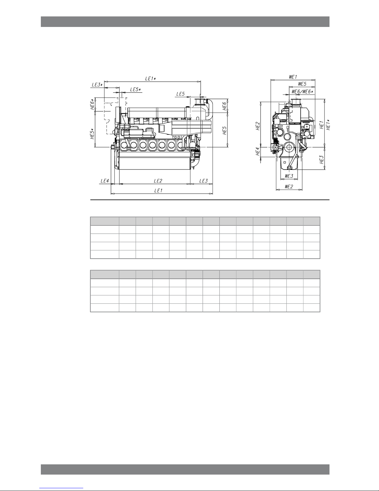
Fig 1-1 In-line engines with 500kW/cyl (DAAE030112A)
WE2WE3LE4LE2HE3HE4HE2WE1HE1HE1*LE1LE1*Engine
135088025036701155500234523052490256052604980W 6L32
135088025041601155500234523052490256057505470W 7L32
135088025046501155500234523052295236062455960W 8L32
135088025051401155500234523052295236067306450W 9L32
WeightLE5LE5*WE6WE6*HE6HE6*HE5HE5*LE3LE3*WE5Engine
33.95051303606607107101780185011507751345W 6L32
38.25051303606607107101780185011507751345W 7L32
43.55051303606604204201780185011507751345W 8L32
47.75051303606604204201780185011507751345W 9L32
* Turbocharger at flywheel end.
All dimensions in mm. Weight in metric tons with liquids (wet sump) but without flywheel.
1-4 Wärtsilä 32 Product Guide - a21 - 7 September 2016
Wärtsilä 32 Product Guide1. Main Data and Outputs
Page 11
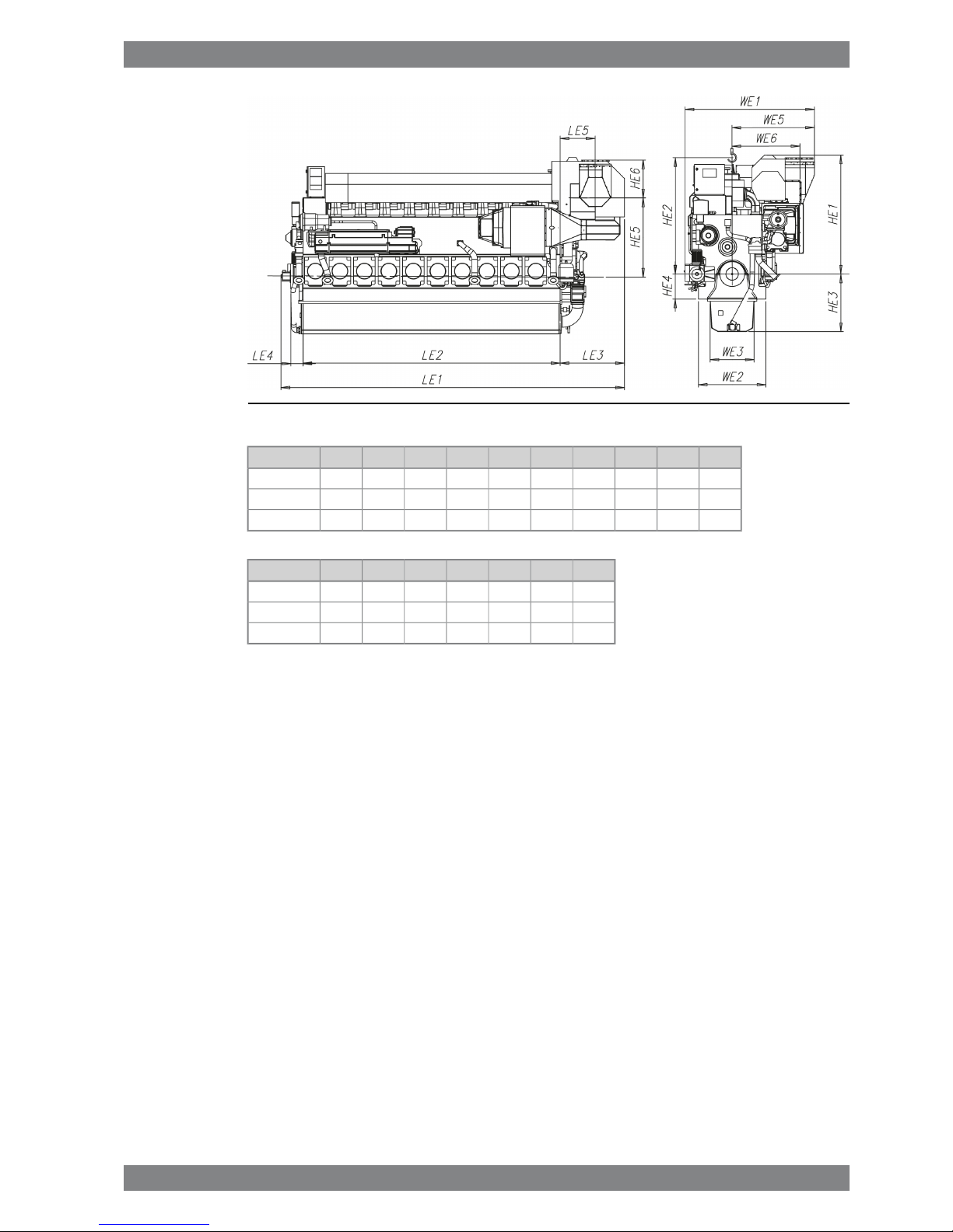
Fig 1-2 In-line engines with 580kW/cyl (DAAF061578A)
WE2WE3LE4LE2HE3HE4HE2WE1HE1LE1Engine
1350880250367011555002345238022955130W 6L32
1350880250465011555002345261023756379W 8L32
1350880250514011555002345261023756869W 9L32
WeightLE5WE6HE6HE5LE3WE5Engine
35.4515375460178012151425W 6L32
43.67051340545178012851650W 8L32
49.27051340545178012851650W 9L32
* Turbocharger at flywheel end.
All dimensions in mm. Weight in metric tons with liquids (wet sump) but without flywheel.
Wärtsilä 32 Product Guide - a21 - 7 September 2016 1-5
1. Main Data and OutputsWärtsilä 32 Product Guide
Page 12
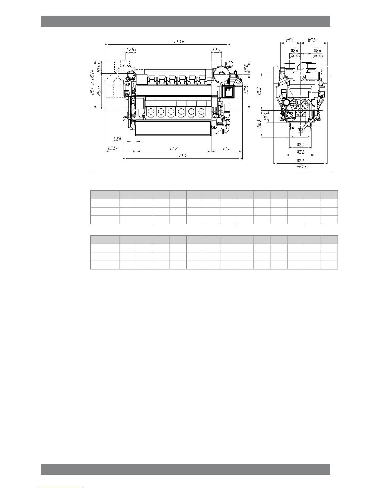
Fig 1-3 V-engines with 500kW/cyl (DAAE035123A)
WE2WE3LE4LE2HE3HE4HE2WE1*WE1HE1*HE1LE1LE1*Engine
15901220300415014756502120302030202715266566156935W 12V32
15901220300527014756502120302030202480243077358060W 16V32
15901220300583014756502120302030202480243082958620W 18V32
WeightLE5LE5*WE6WE6*HE6*HE6HE5*HE5WE4LE3LE3*WE5Engine
59.559059060060071071019651915850173517351510W 12V32
73.559059060060042042019651915850173517351510W 16V32
78.959059060060042042019651915850173517351510W 18V32
* Turbocharger at flywheel end.
All dimensions in mm. Weight in metric tons with liquids (wet sump) but without flywheel.
1-6 Wärtsilä 32 Product Guide - a21 - 7 September 2016
Wärtsilä 32 Product Guide1. Main Data and Outputs
Page 13
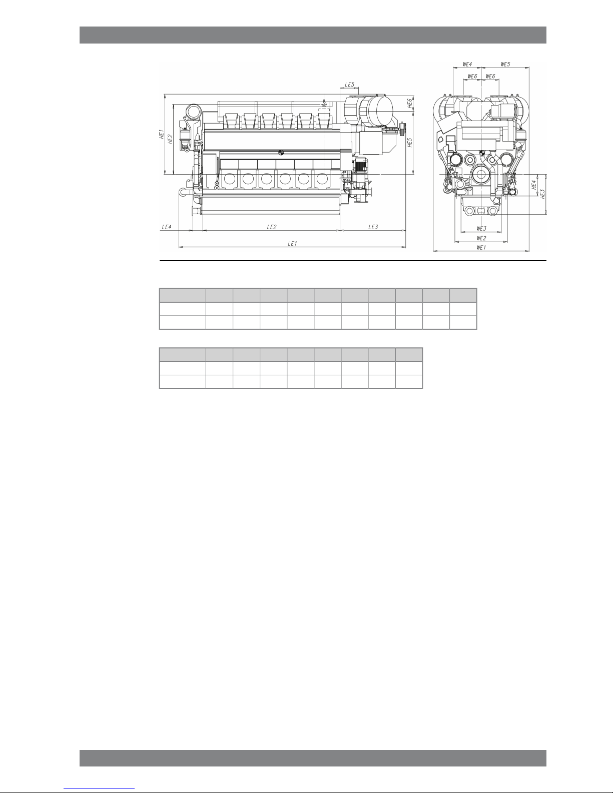
Fig 1-4 V-engines with 580kW/cyl (DAAF062155)
WE2WE3LE4LE2HE3HE4HE2WE1HE1LE1Engine
15901225300415012106502120290024306865W 12V32
15901225300527012106502120332525957905W 16V32
WeightLE5WE6HE6HE5WE4LE3WE5Engine
56.9555540470190585019851450W 12V32
71.1560575550202085019251665W 16V32
* Turbocharger at flywheel end.
All dimensions in mm. Weight in metric tons with liquids (wet sump) but without flywheel.
Wärtsilä 32 Product Guide - a21 - 7 September 2016 1-7
1. Main Data and OutputsWärtsilä 32 Product Guide
Page 14
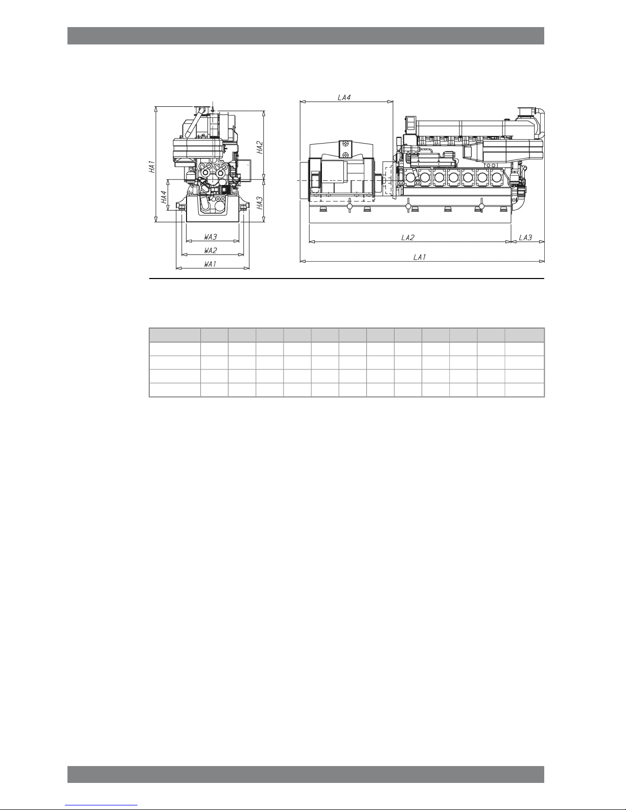
1.5.2 Generating sets
Fig 1-5 In-line engines with 500kW/cyl (DAAE030093)
* Actual dimensions might vary based on power output and turbocharger maker.
Weight**HA1HA2HA3HA4WA3WA2WA1LA4**LA2**LA3LA1**Engine
5739402345145010461600191022903160684511508345W 6L32
6941402345165010462000231026903650751511509215W 7L32
7739252345163010462000231026903710792011509755W 8L32
84392523451630104622002510289038258850115010475W 9L32
** Dependent on generator and flexible coupling.
All dimensions in mm. Weight in metric tons with liquids.
1-8 Wärtsilä 32 Product Guide - a21 - 7 September 2016
Wärtsilä 32 Product Guide1. Main Data and Outputs
Page 15
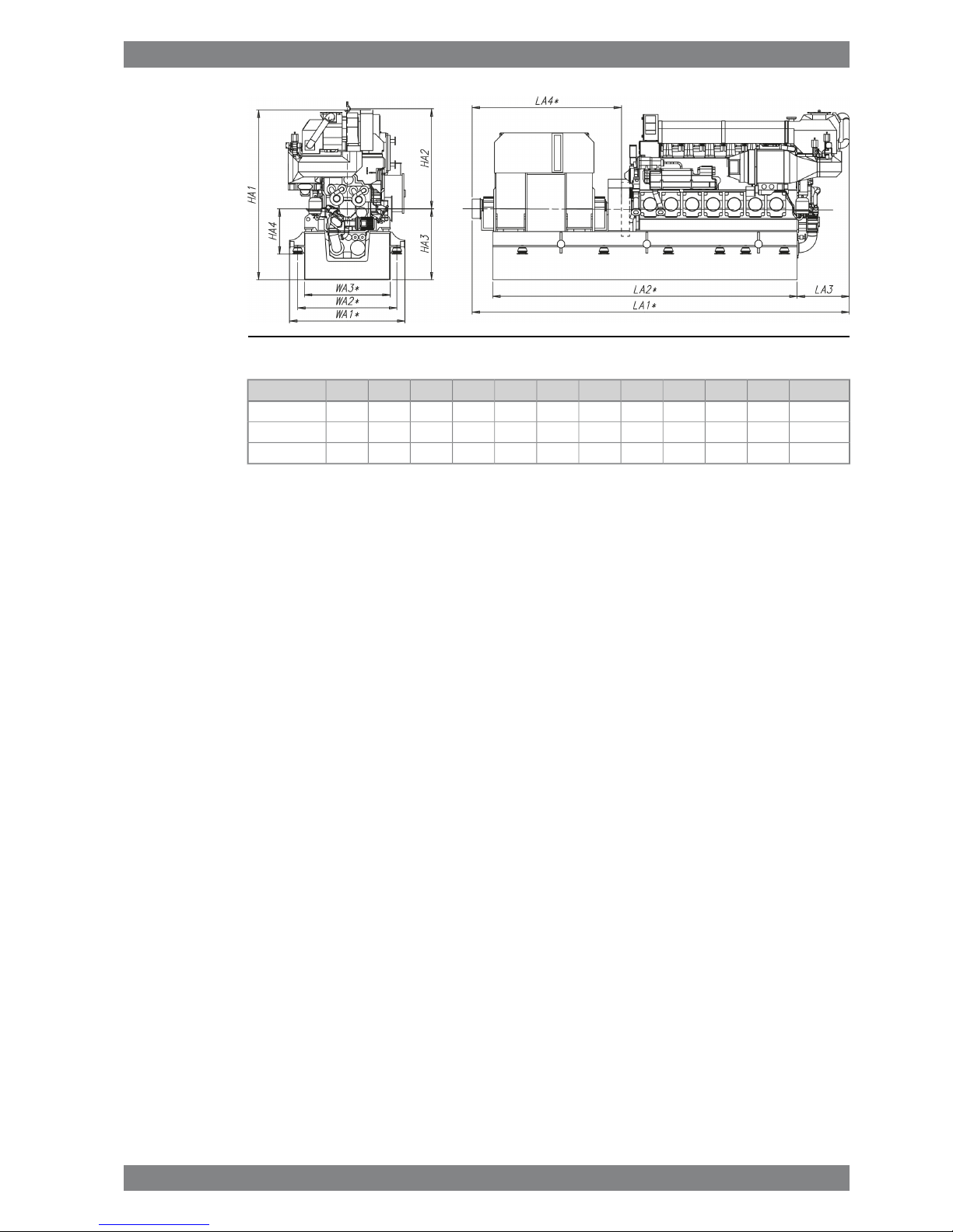
Fig 1-6 In-line engines with 580kW/cyl (DAAF061592)
Weight**HA1HA2HA3HA4WA3*WA2*WA1*LA4*LA2*LA3LA1*Engine
56.98537452345145010461800211024903265687512158345W 6L32
75.760401023451630104620002310269037108555128510410W 8L32
85.650401023451630104622002510289038258870128510505W 9L32
* Dependent on generator and flexible coupling.
All dimensions in mm. Weight in metric tons with liquids.
Wärtsilä 32 Product Guide - a21 - 7 September 2016 1-9
1. Main Data and OutputsWärtsilä 32 Product Guide
Page 16

Fig 1-7 V-engines with 500kW/cyl (DAAE039700B)
* Actual dimensions might vary based on power output and turbocharger maker.
Weight**HA1HA2HA3HA4WA3WA2WA1LA4**LA2**LA3LA1**Engine
96436521201700137522002620306037757955173510075W 12V32
121428021201850137522002620306037659020173511175W 16V32
133428021201850137525002920336038759690173511825W 18V32
** Dependent on generator and flexible coupling.
All dimensions in mm. Weight in metric tons with liquids.
1-10 Wärtsilä 32 Product Guide - a21 - 7 September 2016
Wärtsilä 32 Product Guide1. Main Data and Outputs
Page 17
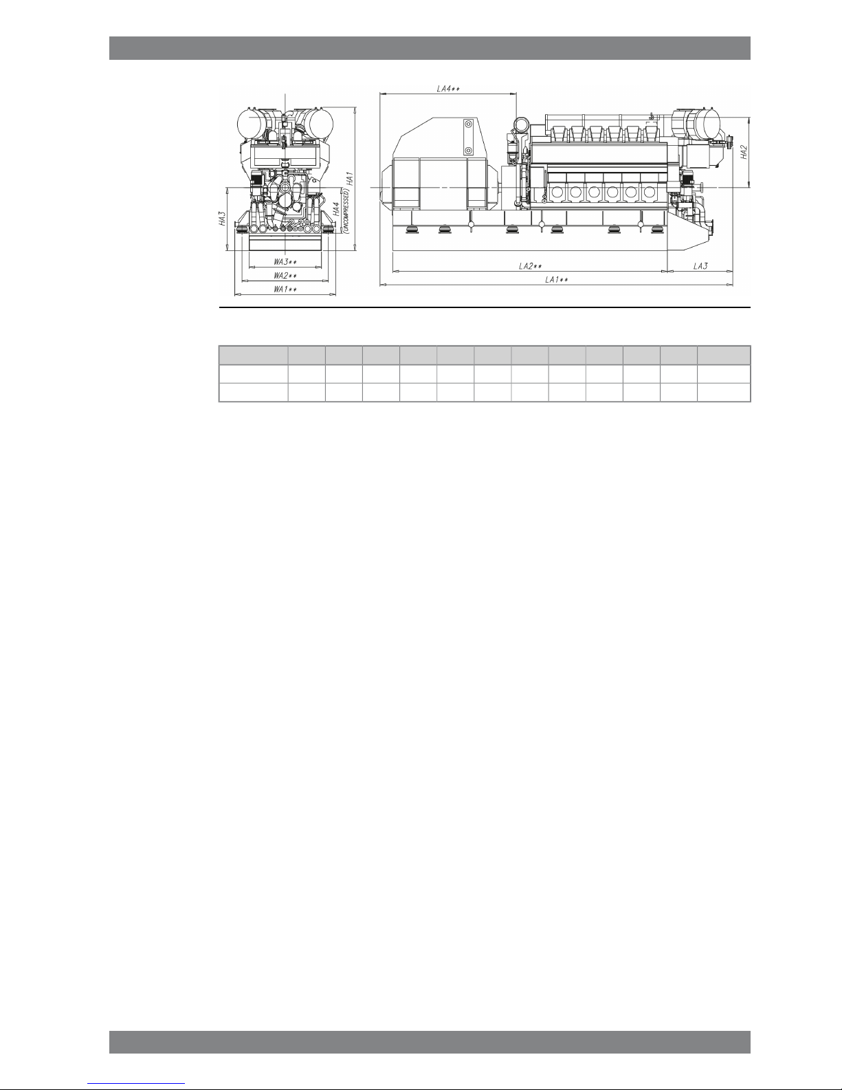
Fig 1-8 V-engines with 580kW/cyl (DAAF061875)
Weight**HA1HA2HA3HA4WA3WA2WA1LA4**LA2**LA3LA1**Engine
100.1413021201700137522002620306041308325198510700W 12V32
127.3444521201850137525002920336042459130192511465W 16V32
** Dependent on generator and flexible coupling.
All dimensions in mm. Weight in metric tons with liquids.
Wärtsilä 32 Product Guide - a21 - 7 September 2016 1-11
1. Main Data and OutputsWärtsilä 32 Product Guide
Page 18

This page intentionally left blank
Page 19

2. Operating Ranges
2.1 Engine operating modes
If the engine is configured for SCR use then it can be operated in two modes; IMO Tier 2 mode
and SCR mode. The mode can be selected by an input signal to the engine automation system.
In SCR mode the exhaust gas temperatures after the turbocharger are actively monitored and
adjusted to stay within the operating temperature window of the SCR.
2.2 Engine operating range
Below nominal speed the load must be limited according to the diagrams in this chapter in
order to maintain engine operating parameters within acceptable limits. Operation in the
shaded area is permitted only temporarily during transients. Minimum speed is indicated in
the diagram, but project specific limitations may apply.
2.2.1 Controllable pitch propellers
An automatic load control system is required to protect the engine from overload. The load
control reduces the propeller pitch automatically, when a pre-programmed load versus speed
curve (“engine limit curve”) is exceeded, overriding the combinator curve if necessary. The
engine load is derived from fuel rack position and actual engine speed (not speed demand).
The propulsion control must also include automatic limitation of the load increase rate.
Maximum loading rates can be found later in this chapter.
The propeller efficiency is highest at design pitch. It is common practice to dimension the
propeller so that the specified ship speed is attained with design pitch, nominal engine speed
and 85% output in the specified loading condition. The power demand from a possible shaft
generator or PTO must be taken into account. The 15% margin is a provision for weather
conditions and fouling of hull and propeller. An additional engine margin can be applied for
most economical operation of the engine, or to have reserve power.
Wärtsilä 32 Product Guide - a21 - 7 September 2016 2-1
2. Operating RangesWärtsilä 32 Product Guide
Page 20
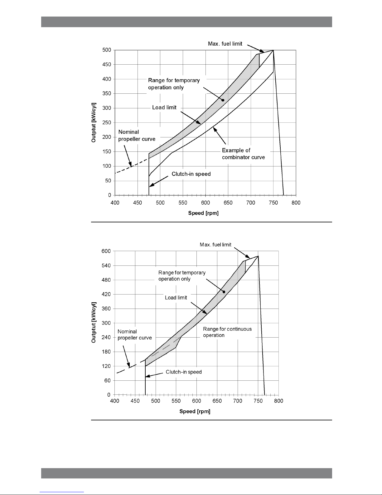
Fig 2-1 Operating field for CP Propeller, 500 kW/cyl, 750 rpm
Fig 2-2 Operating field for CP Propeller, 580 kW/cyl, 750 rpm
2-2 Wärtsilä 32 Product Guide - a21 - 7 September 2016
Wärtsilä 32 Product Guide2. Operating Ranges
Page 21
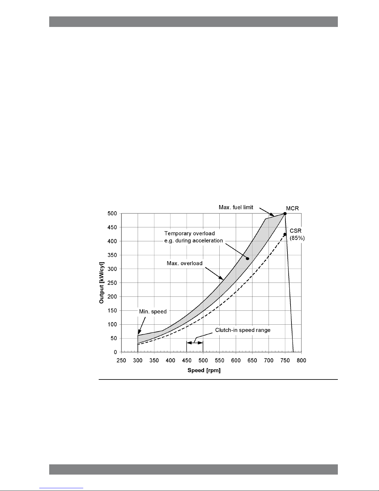
2.2.2 Fixed pitch propellers
The thrust and power absorption of a given fixed pitch propeller is determined by the relation
between ship speed and propeller revolution speed. The power absorption during acceleration,
manoeuvring or towing is considerably higher than during free sailing for the same revolution
speed. Increased ship resistance, for reason or another, reduces the ship speed, which
increases the power absorption of the propeller over the whole operating range.
Loading conditions, weather conditions, ice conditions, fouling of hull, shallow water, and
manoeuvring requirements must be carefully considered, when matching a fixed pitch propeller
to the engine. The nominal propeller curve shown in the diagram must not be exceeded in
service, except temporarily during acceleration and manoeuvring. A fixed pitch propeller for
a free sailing ship is therefore dimensioned so that it absorbs max. 85% of the engine output
at nominal engine speed during trial with loaded ship. Typically this corresponds to about
82% for the propeller itself.
If the vessel is intended for towing, the propeller is dimensioned to absorb 95% of the engine
power at nominal engine speed in bollard pull or towing condition. It is allowed to increase
the engine speed to 101.7% in order to reach 100% MCR during bollard pull.
A shaft brake should be used to enable faster reversing and shorter stopping distance (crash
stop). The ship speed at which the propeller can be engaged in reverse direction is still limited
by the windmilling torque of the propeller and the torque capability of the engine at low
revolution speed.
Fig 2-3 Operating field for FP Propeller, 500 kW/cyl), 750 rpm
2.2.3 Dredgers
Mechanically driven dredging pumps typically require a capability to operate with full torque
down to 80% of nominal engine speed. This requirement results in significant de-rating of the
engine.
Wärtsilä 32 Product Guide - a21 - 7 September 2016 2-3
2. Operating RangesWärtsilä 32 Product Guide
Page 22
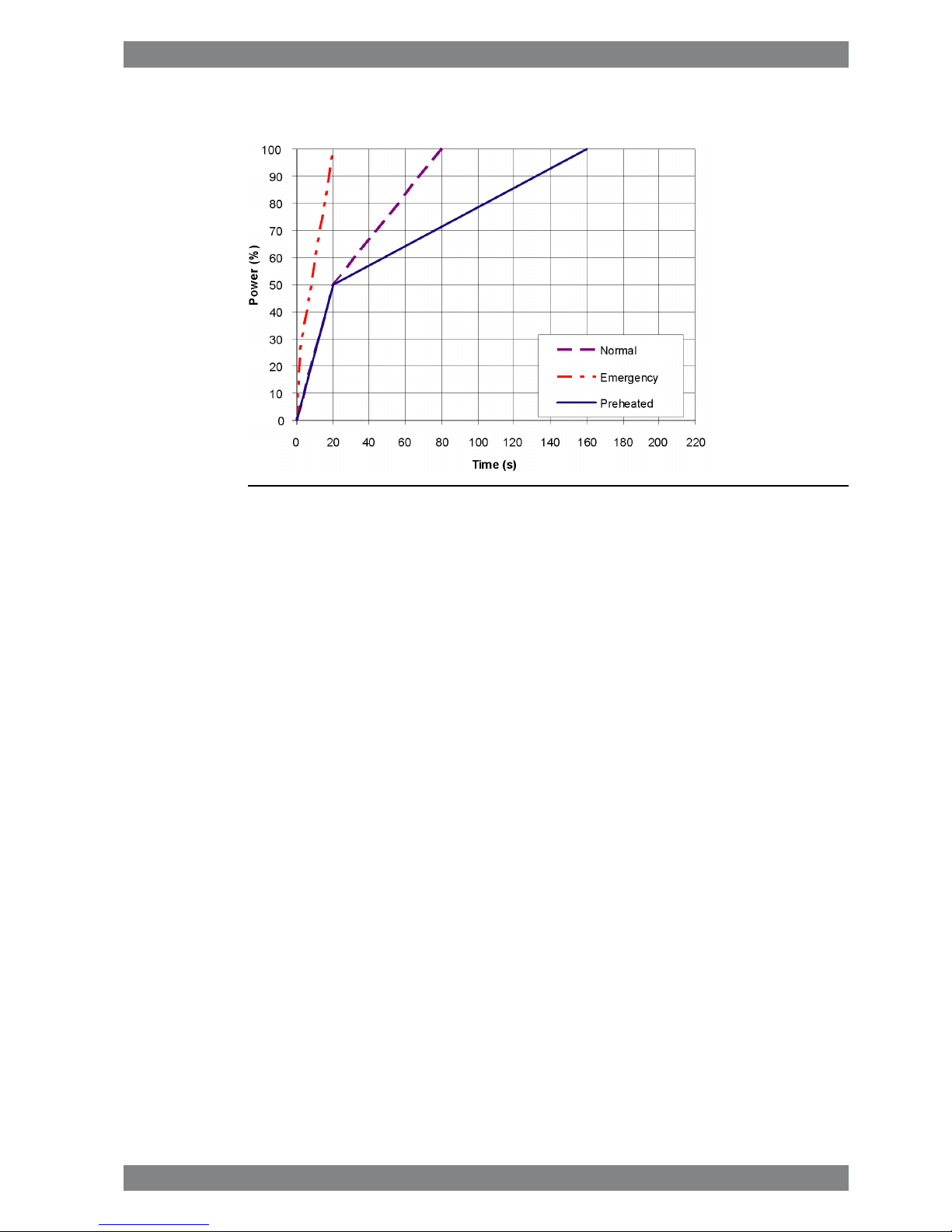
2.3 Loading capacity
Controlled load increase is essential for highly supercharged diesel engines, because the
turbocharger needs time to accelerate before it can deliver the required amount of air. A slower
loading ramp than the maximum capability of the engine permits a more even temperature
distribution in engine components during transients.
The engine can be loaded immediately after start, provided that the engine is pre-heated to
a HT-water temperature of 60…70ºC, and the lubricating oil temperature is min. 40 ºC.
The ramp for normal loading applies to engines that have reached normal operating
temperature.
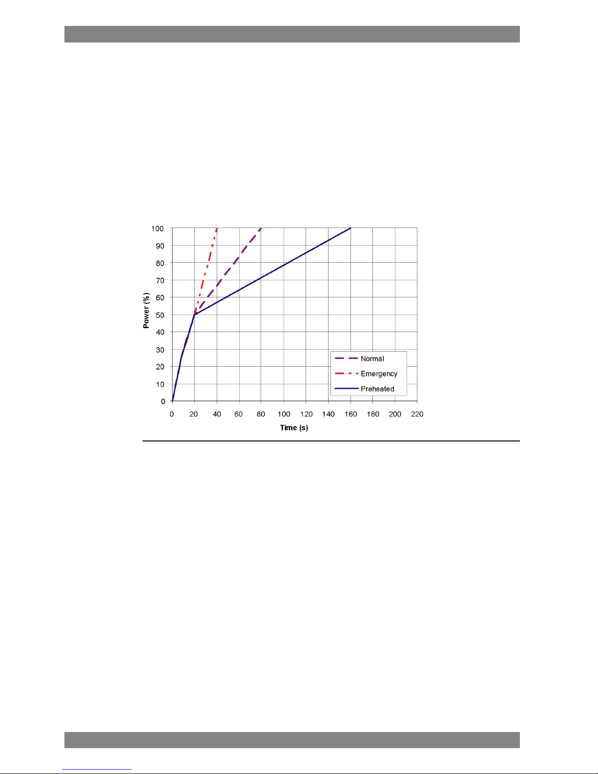
2.3.1 Mechanical propulsion
Fig 2-4 Maximum recommended load increase rates for variable speed engines
The propulsion control must include automatic limitation of the load increase rate. If the control
system has only one load increase ramp, then the ramp for a preheated engine should be
used. In tug applications the engines have usually reached normal operating temperature
before the tug starts assisting. The “emergency” curve is close to the maximum capability of
the engine.
If minimum smoke during load increase is a major priority, slower loading rate than in the
diagram can be necessary below 50% load.
Large load reductions from high load should also be performed gradually. In normal operation
the load should not be reduced from 100% to 0% in less than 15 seconds. When absolutely
necessary, the load can be reduced as fast as the pitch setting system can react (overspeed
due to windmilling must be considered for high speed ships).
2-4 Wärtsilä 32 Product Guide - a21 - 7 September 2016
Wärtsilä 32 Product Guide2. Operating Ranges
Page 23
2.3.2 Diesel electric propulsion and auxiliary engines
Fig 2-5 Maximum recommended load increase rates for engines operating at
nominal speed
In diesel electric installations loading ramps are implemented both in the propulsion control
and in the power management system, or in the engine speed control in case isochronous
load sharing is applied. If a ramp without knee-point is used, it should not achieve 100% load
in shorter time than the ramp in the figure. When the load sharing is based on speed droop,
the load increase rate of a recently connected generator is the sum of the load transfer
performed by the power management system and the load increase performed by the
propulsion control.
The “emergency” curve is close to the maximum capability of the engine and it shall not be
used as the normal limit. In dynamic positioning applications loading ramps corresponding to
20-30 seconds from zero to full load are however normal. If the vessel has also other operating
modes, a slower loading ramp is recommended for these operating modes.
In typical auxiliary engine applications there is usually no single consumer being decisive for
the loading rate. It is recommended to group electrical equipment so that the load is increased
in small increments, and the resulting loading rate roughly corresponds to the “normal” curve.
In normal operation the load should not be reduced from 100% to 0% in less than 15 seconds.
If the application requires frequent unloading at a significantly faster rate, special arrangements
can be necessary on the engine. In an emergency situation the full load can be thrown off
instantly.
2.3.2.1 Maximum instant load steps (500 kW/cyl)
The electrical system must be designed so that tripping of breakers can be safely handled.
This requires that the engines are protected from load steps exceeding their maximum load
acceptance capability. The maximum permissible load step is 33% MCR. The resulting speed
drop is less than 10% and the recovery time to within 1% of the steady state speed at the
new load level is max. 5 seconds.
When electrical power is restored after a black-out, consumers are reconnected in groups,
which may cause significant load steps. The engine must be allowed to recover for at least
10 seconds before applying the following load step, if the load is applied in maximum steps.
Wärtsilä 32 Product Guide - a21 - 7 September 2016 2-5
2. Operating RangesWärtsilä 32 Product Guide
Page 24

2.3.2.2 Maximum instant load steps (580 kW/cyl)
The electrical system must be designed so that tripping of breakers can be safely handled.
This requires that the engines are protected from load steps exceeding their maximum load
acceptance capability. The maximum load steps are 0-28-60-100% MCR without air assist.
Engines driving generators are prepared for air assist, see chapters Technical data and Exhaust
gas system. Sudden load steps equal to 33% MCR can be absorbed also at low load if air
assist is used. If air assist is used, the arrangement of the air supply must be approved by the
classification society.
When electrical power is restored after a black-out, consumers are reconnected in groups,
which may cause significant load steps. The engine must be allowed to recover for at least
10 seconds before applying the following load step, if the load is applied in maximum steps.
2.3.2.3 Start-up time
A diesel generator typically reaches nominal speed in about 20 seconds after the start signal.
The acceleration is limited by the speed control to minimise smoke during start-up. If requested
faster starting times can be arranged.
2.4 Operation at low load and idling
The engine can be started, stopped and operated on heavy fuel under all operating conditions.
Continuous operation on heavy fuel is preferred rather than changing over to diesel fuel at low
load operation and manoeuvring. The following recommendations apply:
Absolute idling (declutched main engine, disconnected generator)
● Maximum 10 minutes if the engine is to be stopped after the idling. 3-5 minutes idling
before stop is recommended.
● Maximum 6 hours if the engine is to be loaded after the idling.
Operation below 20 % load
● Maximum 100 hours continuous operation. At intervals of 100 operating hours the engine
must be loaded to minimum 70 % of the rated output.
Operation above 20 % load
● No restrictions.
NOTE
For operation profiles involving prolonged low load operation, please contact
Wärtsilä.
2.5 Low air temperature
In cold conditions the following minimum inlet air temperatures apply:
● Starting + 5ºC (when running)
● Idling and highload - 5ºC
For lower suction air temperatures engines shall be configured for arctic operation.
For further guidelines, see chapter Combustion air system design.
2-6 Wärtsilä 32 Product Guide - a21 - 7 September 2016
Wärtsilä 32 Product Guide2. Operating Ranges
Page 25
3. Technical Data
3.1 Wärtsilä 6L32, 720 rpm
DE
SCR
mode
AE
SCR
mode
DE
IMO
Tier 2
AE
IMO
Tier 2
Wärtsilä 6L32
720
560
720
560
720
560
720
560
RPM
kW/cyl
Engine speed
Cylinder output
3360336033603360kWEngine output
2.92.92.92.9MPaMean effective pressure
Combustion air system (Note 1)
6.026.026.026.02kg/sFlow at 100% load
45454545°CTemperature at turbocharger intake, max.
55555555°CAir temperature after air cooler (TE 601)
Exhaust gas system (Note 2)
6.26.26.26.2kg/sFlow at 100% load
5.25.25.45.4kg/sFlow at 85% load
4.84.85.05.0kg/sFlow at 75% load
3.33.33.33.3kg/sFlow at 50% load
350350350350°CTemperature after turbocharger, 100% load (TE 517)
340340330330°CTemperature after turbocharger, 85% load (TE 517)
340340330330°CTemperature after turbocharger, 75% load (TE 517)
380380380380°CTemperature after turbocharger, 50% load (TE 517)
5.05.05.05.0kPaBackpressure, max.
629629629629
mmCalculated pipe diameter for 35m/s
Heat balance (Note 3)
430430430430kWJacket water, HT-circuit
766766766766kWCharge air, HT-circuit
414414414414kWCharge air, LT-circuit
388388388388kWLubricating oil, LT-circuit
110110110110kWRadiation
Fuel system (Note 4)
700±50700±50700±50700±50kPaPressure before injection pumps (PT 101)
4.34.34.34.3m3/hEngine driven pump capacity (MDF only)
3.43.43.43.4m3/hFuel flow to engine (without engine driven pump),
approx.
16...2416...2416...2416...24cStHFO viscosity before engine
140140140140°CHFO temperature before engine, max. (TE 101)
2.02.02.02.0cStMDF viscosity, min
45454545°CMDF temperature before engine, max. (TE 101)
183184182182
g/kWhFuel consumption at 100% load, HFO
184184181182
g/kWhFuel consumption at 85% load, HFO
184184182182
g/kWhFuel consumption at 75% load, HFO
Wärtsilä 32 Product Guide - a21 - 7 September 2016 3-1
3. Technical DataWärtsilä 32 Product Guide
Page 26
DE
SCR
mode
AE
SCR
mode
DE
IMO
Tier 2
AE
IMO
Tier 2
Wärtsilä 6L32
720
560
720
560
720
560
720
560
RPM
kW/cyl
Engine speed
Cylinder output
190195188193
g/kWhFuel consumption at 50% load, HFO
184185184185
g/kWhFuel consumption at 100% load, MDF
181183180182
g/kWhFuel consumption at 85% load, MDF
182183180182
g/kWhFuel consumption at 75% load, MDF
190191186190
g/kWhFuel consumption at 50% load, MDF
12.812.812.812.8
kg/hClean leak fuel quantity, MDF at 100% load
2.62.62.62.6
kg/hClean leak fuel quantity, HFO at 100% load
Lubricating oil system
500500500500
kPaPressure before bearings, nom. (PT 201)
30303030
kPaSuction ability main pump, including pipe loss,max.
50505050
kPaPriming pressure, nom. (PT 201)
30303030
kPaSuction ability priming pump, including pipe loss,
max.
63636363
°CTemperature before bearings, nom. (TE 201)
78787878
°CTemperature after engine, approx.
78787878
m³/hPump capacity (main), engine driven
67676767
m³/hPump capacity (main), stand-by
15.0 /
18.0
15.0 /
18.0
15.0 /
18.0
15.0 /
18.0
m³/hPriming pump capacity, 50Hz/60Hz
1.61.61.61.6
m³Oil volume, wet sump, nom.
4.54.54.54.5
m³Oil volume in separate system oil tank, nom.
0.350.350.350.35
g/kWhOil consumption (100% load), approx.
1380138013801380l/minCrankcase ventilation flow rate at full load
0.10.10.10.1kPaCrankcase ventilation backpressure, max.
8.5...9.58.5...9.58.5...9.58.5...9.5litersOil volume in turning device
1.91.91.91.9litersOil volume in speed governor
Cooling water system
High temperature cooling water system
250 +
static
250 +
static
250 +
static
250 +
static
kPaPressure at engine, after pump, nom. (PT 401)
530530530530
kPaPressure at engine, after pump, max. (PT 401)
77777777
°CTemperature before cylinders, approx. (TE 401)
96969696°CHT-water out from engine, nom(TE402)(singlestage
CAC)
96969696°CHT-water out from engine, nom (TE432) (two stage
CAC)
60606060
m³/hCapacity of engine driven pump, nom.
100100100100kPaPressure drop over engine, total (single stage CAC)
150150150150kPaPressure drop over engine, total (two stage CAC)
100100100100
kPaPressure drop in external system, max.
3-2 Wärtsilä 32 Product Guide - a21 - 7 September 2016
Wärtsilä 32 Product Guide3. Technical Data
Page 27
DE
SCR
mode
AE
SCR
mode
DE
IMO
Tier 2
AE
IMO
Tier 2
Wärtsilä 6L32
720
560
720
560
720
560
720
560
RPM
kW/cyl
Engine speed
Cylinder output
70...15070...15070...15070...150kPaPressure from expansion tank
0.410.410.410.41
m³Water volume in engine
Low temperature cooling water system
250 +
static
250 +
static
250 +
static
250 +
static
kPaPressure at engine, after pump, nom. (PT 451)
530530530530
kPaPressure at engine, after pump, max. (PT 451)
25 ... 3825 ... 3825 ... 3825 ... 38°CTemperature before engine (TE 451)
60606060
m³/hCapacity of engine driven pump, nom.
35353535
kPaPressure drop over charge air cooler
30303030
kPaPressure drop over oil cooler
100100100100
kPaPressure drop in external system, max.
70 ...
150
70 ...
150
70 ...
150
70 ...
150
kPaPressure from expansion tank
Starting air system (Note 5)
3000300030003000
kPaPressure, nom.
1600160016001600
kPaPressure at engine during start, min. (20°C)
3000300030003000
kPaPressure, max.
1600160016001600
kPaLow pressure limit in air vessels (alarm limit)
2.12.12.12.1
Nm
3
Air consumption per start
----Nm
3
Air consumption per start without propeller shaft
engaged
----Nm
3
Air consumption with automatic start and slowturning
----Nm
3
Air consumption per start with propeller shaft engaged
----Nm
3
Air consumption with automatic start and high inertia
slowturning
1111Nm
3
Air assist consumption (for engines with580 kW/cyl)
Notes:
At ISO 15550 conditions (ambient air temperature 25°C, LT-water 25°C) and 100% load. Flow tolerance 5%.Note 1
At ISO 15550 conditions (ambient air temperature 25°C, LT-water 25°C). Flow tolerance 5% and temperature tolerance
10°C.
Note 2
At ISO 15550 conditions (ambient air temperature 25°C, LT-water 25°C) and 100% load. Tolerance for cooling water heat
10%, tolerance for radiation heat 30%. Fouling factors and a margin to be taken into account when dimensioning heat
exchangers.
Note 3
At ambient conditions according to ISO 15550. Lower calorific value 42 700 kJ/kg. Withengine driven pumps (two cooling
water + one lubricating oil pump). Tolerance 5%. Note; SOI is different for MDO and HFO engines. If the engine is made
for operation on both HFO and MDO, the consumption on both fuels will be according to HFO consumption.
Note 4
Automatic (remote or local) starting air consumption (average) per start, at 20°C for a specific long start impulse (DE/AUX:
2...3 sec, CPP/FPP: 4...6 sec) which is the shortest time required for a safe start.
Note 5
ME = Engine driving propeller, variable speed
AE = Auxiliary engine driving generator
DE = Diesel-Electric engine driving generator
Subject to revision without notice.
Wärtsilä 32 Product Guide - a21 - 7 September 2016 3-3
3. Technical DataWärtsilä 32 Product Guide
Page 28
3.2 Wärtsilä 6L32, 750 rpm
ME
SCR
mode
DE
SCR
mode
AE
SCR
mode
ME
IMO
Tier 2
DE
IMO
Tier 2
AE
IMO
Tier 2
Wärtsilä 6L32
750
580
750
580
750
580
750
580
750
580
750
580
RPM
kW/cyl
Engine speed
Cylinder output
348034803480348034803480kWEngine output
2.882.882.882.882.882.88MPaMean effective pressure
Combustion air system (Note 1)
6.116.316.316.116.316.31kg/sFlow at 100% load
454545454545°CTemperature at turbocharger intake, max.
555555555555°CAir temperature after air cooler (TE 601)
Exhaust gas system (Note 2)
6.36.56.56.36.56.5kg/sFlow at 100% load
5.45.45.45.65.85.8kg/sFlow at 85% load
4.94.94.94.95.35.3kg/sFlow at 75% load
3.43.63.63.43.63.6kg/sFlow at 50% load
370350350370350350°CTemperature after turbocharger, 100% load
(TE 517)
340340340330320320°CTemperature after turbocharger, 85% load
(TE 517)
340340340340320320°CTemperature after turbocharger, 75% load
(TE 517)
350360360350360360°CTemperature after turbocharger, 50% load
(TE 517)
5.05.05.05.05.05.0kPaBackpressure, max.
644644644644644644
mmCalculated pipe diameter for 35m/s
Heat balance (Note 3)
440449449440449449kWJacket water, HT-circuit
811799799811799799kWCharge air, HT-circuit
489481481489481481kWCharge air, LT-circuit
396405405396405405kWLubricating oil, LT-circuit
110110110110110110kWRadiation
Fuel system (Note 4)
700±50700±50700±50700±50700±50700±50kPaPressure before injection pumps (PT 101)
4.54.54.54.54.54.5m3/hEngine driven pump capacity (MDF only)
3.53.53.63.53.53.5m3/hFuel flow to engine (without engine driven
pump), approx.
16...2416...2416...2416...2416...2416...24cStHFO viscosity before engine
140140140140140140°CHFO temperature before engine, max. (TE
101)
2.02.02.02.02.02.0cStMDF viscosity, min
454545454545°CMDF temperature before engine, max. (TE
101)
184185185183183184
g/kWhFuel consumption at 100% load, HFO
183185185180182183
g/kWhFuel consumption at 85% load, HFO
183185185180182183
g/kWhFuel consumption at 75% load, HFO
3-4 Wärtsilä 32 Product Guide - a21 - 7 September 2016
Wärtsilä 32 Product Guide3. Technical Data
Page 29
ME
SCR
mode
DE
SCR
mode
AE
SCR
mode
ME
IMO
Tier 2
DE
IMO
Tier 2
AE
IMO
Tier 2
Wärtsilä 6L32
750
580
750
580
750
580
750
580
750
580
750
580
RPM
kW/cyl
Engine speed
Cylinder output
185190195182188193
g/kWhFuel consumption at 50% load, HFO
185185186185185186
g/kWhFuel consumption at 100% load, MDF
181182184180181183
g/kWhFuel consumption at 85% load, MDF
181182184180181183
g/kWhFuel consumption at 75% load, MDF
182190191180186190
g/kWhFuel consumption at 50% load, MDF
13.413.413.413.413.413.4
kg/hClean leak fuel quantity, MDF at 100% load
2.72.72.72.72.72.7
kg/hClean leak fuel quantity, HFO at 100% load
Lubricating oil system
500500500500500500
kPaPressure before bearings, nom. (PT 201)
303030303030
kPaSuction ability main pump, including pipe
loss, max.
505050505050
kPaPriming pressure, nom. (PT 201)
303030303030
kPaSuction ability priming pump, including pipe
loss, max.
636363636363
°CTemperature before bearings, nom. (TE 201)
787878787878
°CTemperature after engine, approx.
818181818181
m³/hPump capacity (main), engine driven
707070707070
m³/hPump capacity (main), stand-by
15.0 /
18.0
15.0 /
18.0
15.0 /
18.0
15.0 /
18.0
15.0 /
18.0
15.0 /
18.0
m³/hPriming pump capacity, 50Hz/60Hz
1.61.61.61.61.61.6
m³Oil volume, wet sump, nom.
4.74.74.74.74.74.7
m³Oil volume in separate system oil tank, nom.
0.350.350.350.350.350.35
g/kWhOil consumption (100% load), approx.
138013801380138013801380l/minCrankcase ventilation flow rate at full load
0.10.10.10.10.10.1kPaCrankcase ventilation backpressure, max.
8.5...9.58.5...9.58.5...9.58.5...9.58.5...9.58.5...9.5litersOil volume in turning device
1.91.91.91.91.91.9litersOil volume in speed governor
Cooling water system
High temperature cooling water system
250 +
static
250 +
static
250 +
static
250 +
static
250 +
static
250 +
static
kPaPressure atengine,after pump, nom. (PT 401)
530530530530530530
kPaPressure atengine, after pump, max. (PT 401)
777777777777
°CTemperature before cylinders, approx. (TE
401)
969696969696°CHT-water out from engine, nom (TE402)
(single stage CAC)
969696969696°CHT-water out from engine, nom (TE432) (two
stage CAC)
606060606060
m³/hCapacity of engine driven pump, nom.
100100100100100100kPaPressure drop over engine, total (single stage
CAC)
Wärtsilä 32 Product Guide - a21 - 7 September 2016 3-5
3. Technical DataWärtsilä 32 Product Guide
Page 30
ME
SCR
mode
DE
SCR
mode
AE
SCR
mode
ME
IMO
Tier 2
DE
IMO
Tier 2
AE
IMO
Tier 2
Wärtsilä 6L32
750
580
750
580
750
580
750
580
750
580
750
580
RPM
kW/cyl
Engine speed
Cylinder output
150150150150150150kPaPressure drop over engine, total (two stage
CAC)
100100100100100100
kPaPressure drop in external system, max.
70...15070...15070...15070...15070...15070...150kPaPressure from expansion tank
0.410.410.410.410.410.41
m³Water volume in engine
Low temperature cooling water system
250 +
static
250 +
static
250 +
static
250 +
static
250 +
static
250 +
static
kPaPressure atengine,after pump, nom. (PT 451)
530530530530530530
kPaPressure atengine, after pump, max. (PT 451)
25 ...
38
25 ...
38
25 ...
38
25 ...
38
25 ...
38
25 ...
38
°CTemperature before engine (TE 451)
606060606060
m³/hCapacity of engine driven pump, nom.
353535353535
kPaPressure drop over charge air cooler
303030303030
kPaPressure drop over oil cooler
100100100100100100
kPaPressure drop in external system, max.
70 ...
150
70 ...
150
70 ...
150
70 ...
150
70 ...
150
70 ...
150
kPaPressure from expansion tank
Starting air system (Note 5)
300030003000300030003000
kPaPressure, nom.
160016001600160016001600
kPaPressure at engine during start, min. (20°C)
300030003000300030003000
kPaPressure, max.
160016001600160016001600
kPaLow pressure limit in air vessels (alarm limit)
-
2.12.1
-
2.12.1
Nm
3
Air consumption per start
2.1
--
2.1
--Nm
3
Air consumption per start without propeller
shaft engaged
------Nm
3
Air consumption with automatic start and
slowturning
3.4
--
3.4
--Nm
3
Air consumption per start with propeller shaft
engaged
------Nm
3
Air consumption with automatic start and high
inertia slowturning
111111Nm
3
Air assist consumption (for engines with 580
kW/cyl)
Notes:
At ISO 15550 conditions (ambient air temperature 25°C, LT-water 25°C) and 100% load. Flow tolerance 5%.Note 1
At ISO 15550 conditions (ambient air temperature 25°C, LT-water 25°C). Flow tolerance 5% and temperature tolerance
10°C.
Note 2
At ISO 15550 conditions (ambient air temperature 25°C, LT-water 25°C) and 100% load. Tolerance for cooling water heat
10%, tolerance for radiation heat 30%. Fouling factors and a margin to be taken into account when dimensioning heat
exchangers.
Note 3
At ambient conditions according to ISO 15550. Lower calorific value 42 700 kJ/kg. Withengine driven pumps (two cooling
water + one lubricating oil pump). Tolerance 5%. Note; SOI is different for MDO and HFO engines. If the engine is made
for operation on both HFO and MDO, the consumption on both fuels will be according to HFO consumption.
Note 4
Automatic (remote or local) starting air consumption (average) per start, at 20°C for a specific long start impulse (DE/AUX:
2...3 sec, CPP/FPP: 4...6 sec) which is the shortest time required for a safe start.
Note 5
3-6 Wärtsilä 32 Product Guide - a21 - 7 September 2016
Wärtsilä 32 Product Guide3. Technical Data
Page 31

ME = Engine driving propeller, variable speed
AE = Auxiliary engine driving generator
DE = Diesel-Electric engine driving generator
Subject to revision without notice.
Wärtsilä 32 Product Guide - a21 - 7 September 2016 3-7
3. Technical DataWärtsilä 32 Product Guide
Page 32

3.3 Wärtsilä 8L32, 720 rpm
DE
SCR
mode
AE
SCR
mode
DE
IMO
Tier 2
AE
IMO
Tier 2
Wärtsilä 8L32
720
560
720
560
720
560
720
560
RPM
kW/cyl
Engine speed
Cylinder output
4480448044804480kWEngine output
2.92.92.92.9MPaMean effective pressure
Combustion air system (Note 1)
8.068.068.068.06kg/sFlow at 100% load
45454545°CTemperature at turbocharger intake, max.
55555555°CAir temperature after air cooler (TE 601)
Exhaust gas system (Note 2)
8.38.38.38.3kg/sFlow at 100% load
6.96.97.27.2kg/sFlow at 85% load
6.46.46.66.6kg/sFlow at 75% load
4.54.54.54.5kg/sFlow at 50% load
350350350350°CTemperature after turbocharger, 100% load (TE 517)
340340330330°CTemperature after turbocharger, 85% load (TE 517)
340340330330°CTemperature after turbocharger, 75% load (TE 517)
380380380380°CTemperature after turbocharger, 50% load (TE 517)
5.05.05.05.0kPaBackpressure, max.
728728728728
mmCalculated pipe diameter for 35m/s
Heat balance (Note 3)
573573573573kWJacket water, HT-circuit
1021102110211021kWCharge air, HT-circuit
552552552552kWCharge air, LT-circuit
517517517517kWLubricating oil, LT-circuit
147147147147kWRadiation
Fuel system (Note 4)
700±50700±50700±50700±50kPaPressure before injection pumps (PT 101)
5.45.45.45.4m3/hEngine driven pump capacity (MDF only)
4.54.54.54.5m3/hFuel flow to engine (without engine driven pump),
approx.
16...2416...2416...2416...24cStHFO viscosity before engine
140140140140°CHFO temperature before engine, max. (TE 101)
2.02.02.02.0cStMDF viscosity, min
45454545°CMDF temperature before engine, max. (TE 101)
183184182182
g/kWhFuel consumption at 100% load, HFO
184184181182
g/kWhFuel consumption at 85% load, HFO
184184182182
g/kWhFuel consumption at 75% load, HFO
190195188193
g/kWhFuel consumption at 50% load, HFO
184185184185
g/kWhFuel consumption at 100% load, MDF
181183180182
g/kWhFuel consumption at 85% load, MDF
3-8 Wärtsilä 32 Product Guide - a21 - 7 September 2016
Wärtsilä 32 Product Guide3. Technical Data
Page 33

DE
SCR
mode
AE
SCR
mode
DE
IMO
Tier 2
AE
IMO
Tier 2
Wärtsilä 8L32
720
560
720
560
720
560
720
560
RPM
kW/cyl
Engine speed
Cylinder output
182183180182
g/kWhFuel consumption at 75% load, MDF
190191186190
g/kWhFuel consumption at 50% load, MDF
17.017.117.017.1
kg/hClean leak fuel quantity, MDF at 100% load
3.43.43.43.4
kg/hClean leak fuel quantity, HFO at 100% load
Lubricating oil system
500500500500
kPaPressure before bearings, nom. (PT 201)
30303030
kPaSuction ability main pump, including pipe loss,max.
50505050
kPaPriming pressure, nom. (PT 201)
30303030
kPaSuction ability priming pump, including pipe loss,
max.
63636363
°CTemperature before bearings, nom. (TE 201)
79797979
°CTemperature after engine, approx.
101101101101
m³/hPump capacity (main), engine driven
91919191
m³/hPump capacity (main), stand-by
21.6 /
25.9
21.6 /
25.9
21.6 /
25.9
21.6 /
25.9
m³/hPriming pump capacity, 50Hz/60Hz
2.02.02.02.0
m³Oil volume, wet sump, nom.
6.06.06.06.0
m³Oil volume in separate system oil tank, nom.
0.350.350.350.35
g/kWhOil consumption (100% load), approx.
1880188018801880l/minCrankcase ventilation flow rate at full load
0.10.10.10.1kPaCrankcase ventilation backpressure, max.
8.5...9.58.5...9.58.5...9.58.5...9.5litersOil volume in turning device
1.91.91.91.9litersOil volume in speed governor
Cooling water system
High temperature cooling water system
250 +
static
250 +
static
250 +
static
250 +
static
kPaPressure at engine, after pump, nom. (PT 401)
530530530530
kPaPressure at engine, after pump, max. (PT 401)
77777777
°CTemperature before cylinders, approx. (TE 401)
96969696°CHT-water out from engine, nom(TE402)(singlestage
CAC)
96969696°CHT-water out from engine, nom (TE432) (two stage
CAC)
75757575
m³/hCapacity of engine driven pump, nom.
100100100100kPaPressure drop over engine, total (single stage CAC)
150150150150kPaPressure drop over engine, total (two stage CAC)
100100100100
kPaPressure drop in external system, max.
70...15070...15070...15070...150kPaPressure from expansion tank
0.510.510.510.51
m³Water volume in engine
Low temperature cooling water system
Wärtsilä 32 Product Guide - a21 - 7 September 2016 3-9
3. Technical DataWärtsilä 32 Product Guide
Page 34

DE
SCR
mode
AE
SCR
mode
DE
IMO
Tier 2
AE
IMO
Tier 2
Wärtsilä 8L32
720
560
720
560
720
560
720
560
RPM
kW/cyl
Engine speed
Cylinder output
250 +
static
250 +
static
250 +
static
250 +
static
kPaPressure at engine, after pump, nom. (PT 451)
530530530530
kPaPressure at engine, after pump, max. (PT 451)
25 ... 3825 ... 3825 ... 3825 ... 38°CTemperature before engine (TE 451)
75757575
m³/hCapacity of engine driven pump, nom.
35353535
kPaPressure drop over charge air cooler
30303030
kPaPressure drop over oil cooler
100100100100
kPaPressure drop in external system, max.
70 ...
150
70 ...
150
70 ...
150
70 ...
150
kPaPressure from expansion tank
Starting air system (Note 5)
3000300030003000
kPaPressure, nom.
1600160016001600
kPaPressure at engine during start, min. (20°C)
3000300030003000
kPaPressure, max.
1600160016001600
kPaLow pressure limit in air vessels (alarm limit)
2.72.72.72.7
Nm
3
Air consumption per start
----Nm
3
Air consumption per start without propeller shaft
engaged
----Nm
3
Air consumption per start with propeller shaft engaged
1.331.331.331.33Nm
3
Air assist consumption (for engines with580 kW/cyl)
Notes:
At ISO 15550 conditions (ambient air temperature 25°C, LT-water 25°C) and 100% load. Flow tolerance 5%.Note 1
At ISO 15550 conditions (ambient air temperature 25°C, LT-water 25°C). Flow tolerance 5% and temperature tolerance
10°C.
Note 2
At ISO 15550 conditions (ambient air temperature 25°C, LT-water 25°C) and 100% load. Tolerance for cooling water heat
10%, tolerance for radiation heat 30%. Fouling factors and a margin to be taken into account when dimensioning heat
exchangers.
Note 3
At ambient conditions according to ISO 15550. Lower calorific value 42 700 kJ/kg. Withengine driven pumps (two cooling
water + one lubricating oil pump). Tolerance 5%. Note; SOI is different for MDO and HFO engines. If the engine is made
for operation on both HFO and MDO, the consumption on both fuels will be according to HFO consumption.
Note 4
Automatic (remote or local) starting air consumption (average) per start, at 20°C for a specific long start impulse (DE/AUX:
2...3 sec, CPP/FPP: 4...6 sec) which is the shortest time required for a safe start.
Note 5
ME = Engine driving propeller, variable speed
AE = Auxiliary engine driving generator
DE = Diesel-Electric engine driving generator
Subject to revision without notice.
3-10 Wärtsilä 32 Product Guide - a21 - 7 September 2016
Wärtsilä 32 Product Guide3. Technical Data
Page 35

3.4 Wärtsilä 8L32, 750 rpm
ME
SCR
mode
DE
SCR
mode
AE
SCR
mode
ME
IMO
Tier 2
DE
IMO
Tier 2
AE
IMO
Tier 2
Wärtsilä 8L32
750
580
750
580
750
580
750
580
750
580
750
580
RPM
kW/cyl
Engine speed
Cylinder output
464046404640464046404640kWEngine output
2.882.882.882.882.882.88MPaMean effective pressure
Combustion air system (Note 1)
8.158.358.358.158.358.35kg/sFlow at 100% load
454545454545°CTemperature at turbocharger intake, max.
555555555555°CAir temperature after air cooler (TE 601)
Exhaust gas system (Note 2)
8.48.68.68.48.68.6kg/sFlow at 100% load
7.27.27.27.57.87.8kg/sFlow at 85% load
6.56.56.56.57.17.1kg/sFlow at 75% load
4.54.84.84.54.84.8kg/sFlow at 50% load
370350350370350350°CTemperature after turbocharger, 100% load
(TE 517)
340340340330320320°CTemperature after turbocharger, 85% load
(TE 517)
340340340340320320°CTemperature after turbocharger, 75% load
(TE 517)
350360360350360360°CTemperature after turbocharger, 50% load
(TE 517)
5.05.05.05.05.05.0kPaBackpressure, max.
744741741744741741
mmCalculated pipe diameter for 35m/s
Heat balance (Note 3)
587599599587599599kWJacket water, HT-circuit
108110651065108110651065kWCharge air, HT-circuit
652641641652641641kWCharge air, LT-circuit
528540540528540540kWLubricating oil, LT-circuit
147147147147147147kWRadiation
Fuel system (Note 4)
700±50700±50700±50700±50700±50700±50kPaPressure before injection pumps (PT 101)
5.65.65.65.65.65.6m3/hEngine driven pump capacity (MDF only)
4.74.74.74.74.74.7m3/hFuel flow to engine (without engine driven
pump), approx.
16...2416...2416...2416...2416...2416...24cStHFO viscosity before engine
140140140140140140°CHFO temperature before engine, max. (TE
101)
2.02.02.02.02.02.0cStMDF viscosity, min
454545454545°CMDF temperature before engine, max. (TE
101)
184185185183183184
g/kWhFuel consumption at 100% load, HFO
183185185180182183
g/kWhFuel consumption at 85% load, HFO
183185185180182183
g/kWhFuel consumption at 75% load, HFO
Wärtsilä 32 Product Guide - a21 - 7 September 2016 3-11
3. Technical DataWärtsilä 32 Product Guide
Page 36

ME
SCR
mode
DE
SCR
mode
AE
SCR
mode
ME
IMO
Tier 2
DE
IMO
Tier 2
AE
IMO
Tier 2
Wärtsilä 8L32
750
580
750
580
750
580
750
580
750
580
750
580
RPM
kW/cyl
Engine speed
Cylinder output
185190195182188193
g/kWhFuel consumption at 50% load, HFO
185185186185185186
g/kWhFuel consumption at 100% load, MDF
181182184180181183
g/kWhFuel consumption at 85% load, MDF
181182184180181183
g/kWhFuel consumption at 75% load, MDF
182190191180186190
g/kWhFuel consumption at 50% load, MDF
17.917.817.917.917.817.9
kg/hClean leak fuel quantity, MDF at 100% load
3.63.63.63.63.63.6
kg/hClean leak fuel quantity, HFO at 100% load
Lubricating oil system
500500500500500500
kPaPressure before bearings, nom. (PT 201)
303030303030
kPaSuction ability main pump, including pipe
loss, max.
505050505050
kPaPriming pressure, nom. (PT 201)
303030303030
kPaSuction ability priming pump, including pipe
loss, max.
636363636363
°CTemperature before bearings, nom. (TE 201)
797979797979
°CTemperature after engine, approx.
105105105105105105
m³/hPump capacity (main), engine driven
959595959595
m³/hPump capacity (main), stand-by
21.6 /
25.9
21.6 /
25.9
21.6 /
25.9
21.6 /
25.9
21.6 /
25.9
21.6 /
25.9
m³/hPriming pump capacity, 50Hz/60Hz
2.02.02.02.02.02.0
m³Oil volume, wet sump, nom.
6.36.36.36.36.36.3
m³Oil volume in separate system oil tank, nom.
0.350.350.350.350.350.35
g/kWhOil consumption (100% load), approx.
188018801880188018801880l/minCrankcase ventilation flow rate at full load
0.10.10.10.10.10.1kPaCrankcase ventilation backpressure, max.
8.5...9.58.5...9.58.5...9.58.5...9.58.5...9.58.5...9.5litersOil volume in turning device
1.91.91.91.91.91.9litersOil volume in speed governor
Cooling water system
High temperature cooling water system
250 +
static
250 +
static
250 +
static
250 +
static
250 +
static
250 +
static
kPaPressure at engine, after pump, nom. (PT401)
530530530530530530
kPaPressure at engine, after pump,max.(PT401)
777777777777
°CTemperature before cylinders, approx. (TE
401)
969696969696°CHT-water out from engine, nom (TE402)
(single stage CAC)
969696969696°CHT-water out from engine, nom (TE432) (two
stage CAC)
807575807575
m³/hCapacity of engine driven pump, nom.
100100100100100100kPaPressure drop over engine, total (single stage
CAC)
150150150150150150kPaPressure drop over engine, total (two stage
CAC)
3-12 Wärtsilä 32 Product Guide - a21 - 7 September 2016
Wärtsilä 32 Product Guide3. Technical Data
Page 37

ME
SCR
mode
DE
SCR
mode
AE
SCR
mode
ME
IMO
Tier 2
DE
IMO
Tier 2
AE
IMO
Tier 2
Wärtsilä 8L32
750
580
750
580
750
580
750
580
750
580
750
580
RPM
kW/cyl
Engine speed
Cylinder output
100100100100100100
kPaPressure drop in external system, max.
70...15070...15070...15070...15070...15070...150kPaPressure from expansion tank
0.510.510.510.510.510.51
m³Water volume in engine
Low temperature cooling water system
250 +
static
250 +
static
250 +
static
250 +
static
250 +
static
250 +
static
kPaPressure at engine, after pump, nom. (PT451)
530530530530530530
kPaPressure at engine, after pump,max.(PT451)
25 ...
38
25 ...
38
25 ...
38
25 ...
38
25 ...
38
25 ...
38
°CTemperature before engine (TE 451)
807575807575
m³/hCapacity of engine driven pump, nom.
353535353535
kPaPressure drop over charge air cooler
303030303030
kPaPressure drop over oil cooler
100100100100100100
kPaPressure drop in external system, max.
70 ...
150
70 ...
150
70 ...
150
70 ...
150
70 ...
150
70 ...
150
kPaPressure from expansion tank
Starting air system (Note 5)
300030003000300030003000
kPaPressure, nom.
160016001600160016001600
kPaPressure at engine during start, min. (20°C)
300030003000300030003000
kPaPressure, max.
160016001600160016001600
kPaLow pressure limit in air vessels (alarm limit)
-
2.72.7
-
2.72.7
Nm
3
Air consumption per start
2.7
--
2.7
--Nm
3
Air consumption per start without propeller
shaft engaged
4.3
--
4.3
--Nm
3
Air consumption per start with propeller shaft
engaged
1.331.331.331.331.331.33Nm
3
Air assist consumption (for engines with 580
kW/cyl)
Notes:
At ISO 15550 conditions (ambient air temperature 25°C, LT-water 25°C) and 100% load. Flow tolerance 5%.Note 1
At ISO 15550 conditions (ambient air temperature 25°C, LT-water 25°C). Flow tolerance 5% and temperature tolerance
10°C.
Note 2
At ISO 15550 conditions (ambient air temperature 25°C, LT-water 25°C) and 100% load. Tolerance for cooling water heat
10%, tolerance for radiation heat 30%. Fouling factors and a margin to be taken into account when dimensioning heat
exchangers.
Note 3
At ambient conditions according to ISO 15550. Lower calorific value 42 700 kJ/kg. Withengine driven pumps (two cooling
water + one lubricating oil pump). Tolerance 5%. Note; SOI is different for MDO and HFO engines. If the engine is made
for operation on both HFO and MDO, the consumption on both fuels will be according to HFO consumption.
Note 4
Automatic (remote or local) starting air consumption (average) per start, at 20°C for a specific long start impulse (DE/AUX:
2...3 sec, CPP/FPP: 4...6 sec) which is the shortest time required for a safe start.
Note 5
ME = Engine driving propeller, variable speed
AE = Auxiliary engine driving generator
DE = Diesel-Electric engine driving generator
Subject to revision without notice.
Wärtsilä 32 Product Guide - a21 - 7 September 2016 3-13
3. Technical DataWärtsilä 32 Product Guide
Page 38

3.5 Wärtsilä 9L32, 720 rpm
DE
SCR
mode
AE
SCR
mode
DE
IMO
Tier 2
AE
IMO
Tier 2
Wärtsilä 9L32
720
560
720
560
720
560
720
560
RPM
kW/cyl
Engine speed
Cylinder output
5040504050405040kWEngine output
2.92.92.92.9MPaMean effective pressure
Combustion air system (Note 1)
9.039.039.039.03kg/sFlow at 100% load
45454545°CTemperature at turbocharger intake, max.
55555555°CAir temperature after air cooler (TE 601)
Exhaust gas system (Note 2)
9.39.39.39.3kg/sFlow at 100% load
7.87.88.18.1kg/sFlow at 85% load
7.27.27.57.5kg/sFlow at 75% load
5.05.05.05.0kg/sFlow at 50% load
350350350350°CTemperature after turbocharger, 100% load (TE 517)
340340330330°CTemperature after turbocharger, 85% load (TE 517)
340340330330°CTemperature after turbocharger, 75% load (TE 517)
380380380380°CTemperature after turbocharger, 50% load (TE 517)
5.05.05.05.0kPaBackpressure, max.
771771771771
mmCalculated pipe diameter for 35m/s
Heat balance (Note 3)
645645645645kWJacket water, HT-circuit
1149114911491149kWCharge air, HT-circuit
621621621621kWCharge air, LT-circuit
582582582582kWLubricating oil, LT-circuit
165165165165kWRadiation
Fuel system (Note 4)
700±50700±50700±50700±50kPaPressure before injection pumps (PT 101)
5.45.45.45.4m3/hEngine driven pump capacity (MDF only)
5.15.15.05.1m3/hFuel flow to engine (without engine driven pump),
approx.
16...2416...2416...2416...24cStHFO viscosity before engine
140140140140°CHFO temperature before engine, max. (TE 101)
2.02.02.02.0cStMDF viscosity, min
45454545°CMDF temperature before engine, max. (TE 101)
183184182182
g/kWhFuel consumption at 100% load, HFO
184184181182
g/kWhFuel consumption at 85% load, HFO
184184182182
g/kWhFuel consumption at 75% load, HFO
190195188193
g/kWhFuel consumption at 50% load, HFO
184185184185
g/kWhFuel consumption at 100% load, MDF
181183180182
g/kWhFuel consumption at 85% load, MDF
3-14 Wärtsilä 32 Product Guide - a21 - 7 September 2016
Wärtsilä 32 Product Guide3. Technical Data
Page 39

DE
SCR
mode
AE
SCR
mode
DE
IMO
Tier 2
AE
IMO
Tier 2
Wärtsilä 9L32
720
560
720
560
720
560
720
560
RPM
kW/cyl
Engine speed
Cylinder output
182183180182
g/kWhFuel consumption at 75% load, MDF
190191186190
g/kWhFuel consumption at 50% load, MDF
19.219.319.219.3
kg/hClean leak fuel quantity, MDF at 100% load
3.83.93.83.9
kg/hClean leak fuel quantity, HFO at 100% load
Lubricating oil system
500500500500
kPaPressure before bearings, nom. (PT 201)
30303030
kPaSuction ability main pump, including pipe loss,max.
50505050
kPaPriming pressure, nom. (PT 201)
30303030
kPaSuction ability priming pump, including pipe loss,
max.
63636363
°CTemperature before bearings, nom. (TE 201)
79797979
°CTemperature after engine, approx.
108108108108
m³/hPump capacity (main), engine driven
96969696
m³/hPump capacity (main), stand-by
21.6 /
25.9
21.6 /
25.9
21.6 /
25.9
21.6 /
25.9
m³/hPriming pump capacity, 50Hz/60Hz
2.32.32.32.3
m³Oil volume, wet sump, nom.
6.86.86.86.8
m³Oil volume in separate system oil tank, nom.
0.350.350.350.35
g/kWhOil consumption (100% load), approx.
2060206020602060l/minCrankcase ventilation flow rate at full load
0.10.10.10.1kPaCrankcase ventilation backpressure, max.
8.5...9.58.5...9.58.5...9.58.5...9.5litersOil volume in turning device
1.91.91.91.9litersOil volume in speed governor
Cooling water system
High temperature cooling water system
250 +
static
250 +
static
250 +
static
250 +
static
kPaPressure at engine, after pump, nom. (PT 401)
530530530530
kPaPressure at engine, after pump, max. (PT 401)
77777777
°CTemperature before cylinders, approx. (TE 401)
96969696°CHT-water out from engine, nom(TE402)(singlestage
CAC)
96969696°CHT-water out from engine, nom (TE432) (two stage
CAC)
85858585
m³/hCapacity of engine driven pump, nom.
100100100100kPaPressure drop over engine, total (single stage CAC)
150150150150kPaPressure drop over engine, total (two stage CAC)
100100100100
kPaPressure drop in external system, max.
70...15070...15070...15070...150kPaPressure from expansion tank
0.560.560.560.56
m³Water volume in engine
Low temperature cooling water system
Wärtsilä 32 Product Guide - a21 - 7 September 2016 3-15
3. Technical DataWärtsilä 32 Product Guide
Page 40

DE
SCR
mode
AE
SCR
mode
DE
IMO
Tier 2
AE
IMO
Tier 2
Wärtsilä 9L32
720
560
720
560
720
560
720
560
RPM
kW/cyl
Engine speed
Cylinder output
250 +
static
250 +
static
250 +
static
250 +
static
kPaPressure at engine, after pump, nom. (PT 451)
530530530530
kPaPressure at engine, after pump, max. (PT 451)
25 ... 3825 ... 3825 ... 3825 ... 38°CTemperature before engine (TE 451)
85858585
m³/hCapacity of engine driven pump, nom.
35353535
kPaPressure drop over charge air cooler
30303030
kPaPressure drop over oil cooler
100100100100
kPaPressure drop in external system, max.
70 ...
150
70 ...
150
70 ...
150
70 ...
150
kPaPressure from expansion tank
Starting air system (Note 5)
3000300030003000
kPaPressure, nom.
1600160016001600
kPaPressure at engine during start, min. (20°C)
3000300030003000
kPaPressure, max.
1600160016001600
kPaLow pressure limit in air vessels (alarm limit)
2.72.72.72.7
Nm
3
Air consumption per start
----Nm
3
Air consumption per start without propeller shaft
engaged
----Nm
3
Air consumption with automatic start and slowturning
----Nm
3
Air consumption per start with propeller shaft engaged
----Nm
3
Air consumption with automatic start and high inertia
slowturning
1.51.51.51.5Nm
3
Air assist consumption (for engines with580 kW/cyl)
Notes:
At ISO 15550 conditions (ambient air temperature 25°C, LT-water 25°C) and 100% load. Flow tolerance 5%.Note 1
At ISO 15550 conditions (ambient air temperature 25°C, LT-water 25°C). Flow tolerance 5% and temperature tolerance
10°C.
Note 2
At ISO 15550 conditions (ambient air temperature 25°C, LT-water 25°C) and 100% load. Tolerance for cooling water heat
10%, tolerance for radiation heat 30%. Fouling factors and a margin to be taken into account when dimensioning heat
exchangers.
Note 3
At ambient conditions according to ISO 15550. Lower calorific value 42 700 kJ/kg. Withengine driven pumps (two cooling
water + one lubricating oil pump). Tolerance 5%. Note; SOI is different for MDO and HFO engines. If the engine is made
for operation on both HFO and MDO, the consumption on both fuels will be according to HFO consumption.
Note 4
Automatic (remote or local) starting air consumption (average) per start, at 20°C for a specific long start impulse (DE/AUX:
2...3 sec, CPP/FPP: 4...6 sec) which is the shortest time required for a safe start.
Note 5
ME = Engine driving propeller, variable speed
AE = Auxiliary engine driving generator
DE = Diesel-Electric engine driving generator
Subject to revision without notice.
3-16 Wärtsilä 32 Product Guide - a21 - 7 September 2016
Wärtsilä 32 Product Guide3. Technical Data
Page 41

3.6 Wärtsilä 9L32, 750 rpm
ME
SCR
mode
DE
SCR
mode
AE
SCR
mode
ME
IMO
Tier 2
DE
IMO
Tier 2
AE
IMO
Tier 2
Wärtsilä 9L32
750
580
750
580
750
580
750
580
750
580
750
580
RPM
kW/cyl
Engine speed
Cylinder output
522052205220522052205220kWEngine output
2.882.882.882.882.882.88MPaMean effective pressure
Combustion air system (Note 1)
9.129.429.429.129.429.42kg/sFlow at 100% load
454545454545°CTemperature at turbocharger intake, max.
555555555555°CAir temperature after air cooler (TE 601)
Exhaust gas system (Note 2)
9.49.79.79.49.79.7kg/sFlow at 100% load
8.18.18.18.48.88.8kg/sFlow at 85% load
7.37.47.47.38.08.0kg/sFlow at 75% load
5.05.45.45.05.45.4kg/sFlow at 50% load
370350350370350350°CTemperature after turbocharger, 100% load
(TE 517)
340340340330320320°CTemperature after turbocharger, 85% load
(TE 517)
340340340340320320°CTemperature after turbocharger, 75% load
(TE 517)
350360360350360360°CTemperature after turbocharger, 50% load
(TE 517)
5.05.05.05.05.05.0kPaBackpressure, max.
787787787787787787
mmCalculated pipe diameter for 35m/s
Heat balance (Note 3)
660674674660674674kWJacket water, HT-circuit
121711991199121711991199kWCharge air, HT-circuit
734722722734722722kWCharge air, LT-circuit
594608608594608608kWLubricating oil, LT-circuit
165165165165165165kWRadiation
Fuel system (Note 4)
700±50700±50700±50700±50700±50700±50kPaPressure before injection pumps (PT 101)
5.65.65.65.65.65.6m3/hEngine driven pump capacity (MDF only)
5.35.35.35.35.35.3m3/hFuel flow to engine (without engine driven
pump), approx.
16...2416...2416...2416...2416...2416...24cStHFO viscosity before engine
140140140140140140°CHFO temperature before engine, max. (TE
101)
2.02.02.02.02.02.0cStMDF viscosity, min
454545454545°CMDF temperature before engine, max. (TE
101)
184185185183183184
g/kWhFuel consumption at 100% load, HFO
183184185180182183
g/kWhFuel consumption at 85% load, HFO
183184185180182183
g/kWhFuel consumption at 75% load, HFO
Wärtsilä 32 Product Guide - a21 - 7 September 2016 3-17
3. Technical DataWärtsilä 32 Product Guide
Page 42

ME
SCR
mode
DE
SCR
mode
AE
SCR
mode
ME
IMO
Tier 2
DE
IMO
Tier 2
AE
IMO
Tier 2
Wärtsilä 9L32
750
580
750
580
750
580
750
580
750
580
750
580
RPM
kW/cyl
Engine speed
Cylinder output
185191195182188193
g/kWhFuel consumption at 50% load, HFO
185185186185185186
g/kWhFuel consumption at 100% load, MDF
181182184180181183
g/kWhFuel consumption at 85% load, MDF
181182184180181183
g/kWhFuel consumption at 75% load, MDF
182190191180186190
g/kWhFuel consumption at 50% load, MDF
20.120.020.120.120.020.1
kg/hClean leak fuel quantity, MDF at 100% load
4.04.04.04.04.04.0
kg/hClean leak fuel quantity, HFO at 100% load
Lubricating oil system
500500500500500500
kPaPressure before bearings, nom. (PT 201)
303030303030
kPaSuction ability main pump, including pipe
loss, max.
505050505050
kPaPriming pressure, nom. (PT 201)
303030303030
kPaSuction ability priming pump, including pipe
loss, max.
636363636363
°CTemperature before bearings, nom. (TE 201)
797979797979
°CTemperature after engine, approx.
112112112112112112
m³/hPump capacity (main), engine driven
100100100100100100
m³/hPump capacity (main), stand-by
21.6 /
25.9
21.6 /
25.9
21.6 /
25.9
21.6 /
25.9
21.6 /
25.9
21.6 /
25.9
m³/hPriming pump capacity, 50Hz/60Hz
2.32.32.32.32.32.3
m³Oil volume, wet sump, nom.
7.07.07.07.07.07.0
m³Oil volume in separate system oil tank, nom.
0.350.350.350.350.350.35
g/kWhOil consumption (100% load), approx.
206020602060206020602060l/minCrankcase ventilation flow rate at full load
0.10.10.10.10.10.1kPaCrankcase ventilation backpressure, max.
8.5...9.58.5...9.58.5...9.58.5...9.58.5...9.58.5...9.5litersOil volume in turning device
1.91.91.91.91.91.9litersOil volume in speed governor
Cooling water system
High temperature cooling water system
250 +
static
250 +
static
250 +
static
250 +
static
250 +
static
250 +
static
kPaPressure at engine, after pump, nom. (PT401)
530530530530530530
kPaPressure at engine, after pump,max.(PT401)
777777777777
°CTemperature before cylinders, approx. (TE
401)
969696969696°CHT-water out from engine, nom (TE402)
(single stage CAC)
969696969696°CHT-water out from engine, nom (TE432) (two
stage CAC)
858585858585
m³/hCapacity of engine driven pump, nom.
100100100100100100kPaPressure drop over engine, total (single stage
CAC)
150150150150150150kPaPressure drop over engine, total (two stage
CAC)
3-18 Wärtsilä 32 Product Guide - a21 - 7 September 2016
Wärtsilä 32 Product Guide3. Technical Data
Page 43

ME
SCR
mode
DE
SCR
mode
AE
SCR
mode
ME
IMO
Tier 2
DE
IMO
Tier 2
AE
IMO
Tier 2
Wärtsilä 9L32
750
580
750
580
750
580
750
580
750
580
750
580
RPM
kW/cyl
Engine speed
Cylinder output
100100100100100100
kPaPressure drop in external system, max.
70...15070...15070...15070...15070...15070...150kPaPressure from expansion tank
0.560.560.560.560.560.56
m³Water volume in engine
Low temperature cooling water system
250 +
static
250 +
static
250 +
static
250 +
static
250 +
static
250 +
static
kPaPressure at engine, after pump, nom. (PT451)
530530530530530530
kPaPressure at engine, after pump,max.(PT451)
25 ...
38
25 ...
38
25 ...
38
25 ...
38
25 ...
38
25 ...
38
°CTemperature before engine (TE 451)
858585858585
m³/hCapacity of engine driven pump, nom.
353535353535
kPaPressure drop over charge air cooler
303030303030
kPaPressure drop over oil cooler
100100100100100100
kPaPressure drop in external system, max.
70 ...
150
70 ...
150
70 ...
150
70 ...
150
70 ...
150
70 ...
150
kPaPressure from expansion tank
Starting air system (Note 5)
300030003000300030003000
kPaPressure, nom.
160016001600160016001600
kPaPressure at engine during start, min. (20°C)
300030003000300030003000
kPaPressure, max.
160016001600160016001600
kPaLow pressure limit in air vessels (alarm limit)
-
2.72.7
-
2.72.7
Nm
3
Air consumption per start
2.7
--
2.7
--Nm
3
Air consumption per start without propeller
shaft engaged
------Nm
3
Air consumption with automatic start and
slowturning
4.3
--
4.3
--Nm
3
Air consumption per start with propeller shaft
engaged
------Nm
3
Air consumption with automatic start and high
inertia slowturning
1.51.51.51.51.51.5Nm
3
Air assist consumption (for engines with 580
kW/cyl)
Notes:
At ISO 15550 conditions (ambient air temperature 25°C, LT-water 25°C) and 100% load. Flow tolerance 5%.Note 1
At ISO 15550 conditions (ambient air temperature 25°C, LT-water 25°C). Flow tolerance 5% and temperature tolerance
10°C.
Note 2
At ISO 15550 conditions (ambient air temperature 25°C, LT-water 25°C) and 100% load. Tolerance for cooling water heat
10%, tolerance for radiation heat 30%. Fouling factors and a margin to be taken into account when dimensioning heat
exchangers.
Note 3
At ambient conditions according to ISO 15550. Lower calorific value 42 700 kJ/kg. Withengine driven pumps (two cooling
water + one lubricating oil pump). Tolerance 5%. Note; SOI is different for MDO and HFO engines. If the engine is made
for operation on both HFO and MDO, the consumption on both fuels will be according to HFO consumption.
Note 4
Automatic (remote or local) starting air consumption (average) per start, at 20°C for a specific long start impulse (DE/AUX:
2...3 sec, CPP/FPP: 4...6 sec) which is the shortest time required for a safe start.
Note 5
ME = Engine driving propeller, variable speed
AE = Auxiliary engine driving generator
Wärtsilä 32 Product Guide - a21 - 7 September 2016 3-19
3. Technical DataWärtsilä 32 Product Guide
Page 44

DE = Diesel-Electric engine driving generator
Subject to revision without notice.
3-20 Wärtsilä 32 Product Guide - a21 - 7 September 2016
Wärtsilä 32 Product Guide3. Technical Data
Page 45

3.7 Wärtsilä 12V32, 720 rpm
DE
SCR
mode
AE
SCR
mode
DE
IMO
Tier 2
AE
IMO
Tier 2
Wärtsilä 12V32
720
560
720
560
720
560
720
560
RPM
kW/cyl
Engine speed
Cylinder output
6720672067206720kWEngine output
2.92.92.92.9MPaMean effective pressure
Combustion air system (Note 1)
12.0512.0512.0512.05kg/sFlow at 100% load
45454545°CTemperature at turbocharger intake, max.
55555555°CAir temperature after air cooler (TE 601)
Exhaust gas system (Note 2)
12.412.412.412.4kg/sFlow at 100% load
10.410.410.710.7kg/sFlow at 85% load
9.69.69.99.9kg/sFlow at 75% load
6.76.76.76.7kg/sFlow at 50% load
350350350350°CTemperature after turbocharger, 100% load (TE 517)
340340330330°CTemperature after turbocharger, 85% load (TE 517)
340340330330°CTemperature after turbocharger, 75% load (TE 517)
380380380380°CTemperature after turbocharger, 50% load (TE 517)
5.05.05.05.0kPaBackpressure, max.
890890890890
mmCalculated pipe diameter for 35m/s
Heat balance (Note 3)
860860860860kWJacket water, HT-circuit
1532153215321532kWCharge air, HT-circuit
828828828828kWCharge air, LT-circuit
776776776776kWLubricating oil, LT-circuit
220220220220kWRadiation
Fuel system (Note 4)
700±50700±50700±50700±50kPaPressure before injection pumps (PT 101)
6.76.86.76.7m3/hFuel flow to engine, approx.
16...2416...2416...2416...24cStHFO viscosity before engine
140140140140°CHFO temperature before engine, max. (TE 101)
2.02.02.02.0cStMDF viscosity, min
45454545°CMDF temperature before engine, max. (TE 101)
182183181181
g/kWhFuel consumption at 100% load, HFO
183183180181
g/kWhFuel consumption at 85% load, HFO
183184181181
g/kWhFuel consumption at 75% load, HFO
189194187192
g/kWhFuel consumption at 50% load, HFO
183184183184
g/kWhFuel consumption at 100% load, MDF
180182179181
g/kWhFuel consumption at 85% load, MDF
181182179181
g/kWhFuel consumption at 75% load, MDF
Wärtsilä 32 Product Guide - a21 - 7 September 2016 3-21
3. Technical DataWärtsilä 32 Product Guide
Page 46

DE
SCR
mode
AE
SCR
mode
DE
IMO
Tier 2
AE
IMO
Tier 2
Wärtsilä 12V32
720
560
720
560
720
560
720
560
RPM
kW/cyl
Engine speed
Cylinder output
189190185189
g/kWhFuel consumption at 50% load, MDF
25.425.525.425.5
kg/hClean leak fuel quantity, MDF at 100% load
5.15.15.15.1
kg/hClean leak fuel quantity, HFO at 100% load
Lubricating oil system
500500500500
kPaPressure before bearings, nom. (PT 201)
40404040
kPaSuction ability main pump, including pipe loss,max.
50505050
kPaPriming pressure, nom. (PT 201)
35353535
kPaSuction ability priming pump, including pipe loss,
max.
63636363
°CTemperature before bearings, nom. (TE 201)
81818181
°CTemperature after engine, approx.
124124124124
m³/hPump capacity (main), engine driven
106106106106
m³/hPump capacity (main), stand-by
38.0 /
45.9
38.0 /
45.9
38.0 /
45.9
38.0 /
45.9
m³/hPriming pump capacity, 50Hz/60Hz
3.03.03.03.0
m³Oil volume, wet sump, nom.
9.19.19.19.1
m³Oil volume in separate system oil tank, nom.
0.350.350.350.35
g/kWhOil consumption (100% load), approx.
2760276027602760l/minCrankcase ventilation flow rate at full load
0.10.10.10.1kPaCrankcase ventilation backpressure, max.
8.5...9.58.5...9.58.5...9.58.5...9.5litersOil volume in turning device
1.91.91.91.9litersOil volume in speed governor
Cooling water system
High temperature cooling water system
250 +
static
250 +
static
250 +
static
250 +
static
kPaPressure at engine, after pump, nom. (PT 401)
530530530530
kPaPressure at engine, after pump, max. (PT 401)
77777777
°CTemperature before cylinders, approx. (TE 401)
96969696°CHT-water out from engine, nom (TE432)
100100100100
m³/hCapacity of engine driven pump, nom.
150150150150kPaPressure drop over engine, total
100100100100
kPaPressure drop in external system, max.
70...15070...15070...15070...150kPaPressure from expansion tank
0.740.740.740.74
m³Water volume in engine
Low temperature cooling water system
250 +
static
250 +
static
250 +
static
250 +
static
kPaPressure at engine, after pump, nom. (PT 451)
530530530530
kPaPressure at engine, after pump, max. (PT 451)
25 ... 3825 ... 3825 ... 3825 ... 38°CTemperature before engine (TE 451)
100100100100
m³/hCapacity of engine driven pump, nom.
3-22 Wärtsilä 32 Product Guide - a21 - 7 September 2016
Wärtsilä 32 Product Guide3. Technical Data
Page 47

DE
SCR
mode
AE
SCR
mode
DE
IMO
Tier 2
AE
IMO
Tier 2
Wärtsilä 12V32
720
560
720
560
720
560
720
560
RPM
kW/cyl
Engine speed
Cylinder output
35353535
kPaPressure drop over charge air cooler
20202020
kPaPressure drop over oil cooler
100100100100
kPaPressure drop in external system, max.
70 ...
150
70 ...
150
70 ...
150
70 ...
150
kPaPressure from expansion tank
Starting air system (Note 5)
3000300030003000
kPaPressure, nom.
1600160016001600
kPaPressure at engine during start, min. (20°C)
3000300030003000
kPaPressure, max.
1600160016001600
kPaLow pressure limit in air vessels (alarm limit)
3.03.03.03.0
Nm
3
Air consumption per start
----Nm
3
Air consumption per start without propeller shaft
engaged
----Nm
3
Air consumption with automatic start and slowturning
----Nm
3
Air consumption per start with propeller shaft engaged
----Nm
3
Air consumption with automatic start and high inertia
slowturning
2222Nm
3
Air assist consumption (for engines with580 kW/cyl)
Notes:
At ISO 15550 conditions (ambient air temperature 25°C, LT-water 25°C) and 100% load. Flow tolerance 5%.Note 1
At ISO 15550 conditions (ambient air temperature 25°C, LT-water 25°C). Flow tolerance 5% and temperature tolerance
10°C.
Note 2
At ISO 15550 conditions (ambient air temperature 25°C, LT-water 25°C) and 100% load. Tolerance for cooling water heat
10%, tolerance for radiation heat 30%. Fouling factors and a margin to be taken into account when dimensioning heat
exchangers.
Note 3
At ambient conditions according to ISO 15550. Lower calorific value 42 700 kJ/kg. Withengine driven pumps (two cooling
water + one lubricating oil pump). Tolerance 5%. Note; SOI is different for MDO and HFO engines. If the engine is made
for operation on both HFO and MDO, the consumption on both fuels will be according to HFO consumption.
Note 4
Automatic (remote or local) starting air consumption (average) per start, at 20°C for a specific long start impulse (DE/AUX:
2...3 sec, CPP/FPP: 4...6 sec) which is the shortest time required for a safe start.
Note 5
ME = Engine driving propeller, variable speed
AE = Auxiliary engine driving generator
DE = Diesel-Electric engine driving generator
Subject to revision without notice.
Wärtsilä 32 Product Guide - a21 - 7 September 2016 3-23
3. Technical DataWärtsilä 32 Product Guide
Page 48

3.8 Wärtsilä 12V32, 750 rpm
ME
SCR
mode
DE
SCR
mode
AE
SCR
mode
ME
IMO
Tier 2
DE
IMO
Tier 2
AE
IMO
Tier 2
Wärtsilä 12V32
750
580
750
580
750
580
750
580
750
580
750
580
RPM
kW/cyl
Engine speed
Cylinder output
696069606960696069606960kWEngine output
2.882.882.882.882.882.88MPaMean effective pressure
Combustion air system (Note 1)
12.2312.5312.5312.2312.5312.53kg/sFlow at 100% load
454545454545°CTemperature at turbocharger intake, max.
555555555555°CAir temperature after air cooler (TE 601)
Exhaust gas system (Note 2)
12.612.912.912.612.912.9kg/sFlow at 100% load
10.810.810.811.211.711.7kg/sFlow at 85% load
9.79.89.89.710.610.6kg/sFlow at 75% load
6.77.17.16.77.17.1kg/sFlow at 50% load
370350350370350350°CTemperature after turbocharger, 100% load
(TE 517)
340340340330320320°CTemperature after turbocharger, 85% load
(TE 517)
340340340340320320°CTemperature after turbocharger, 75% load
(TE 517)
350360360350360360°CTemperature after turbocharger, 50% load
(TE 517)
5.05.05.05.05.05.0kPaBackpressure, max.
911908908911908908
mmCalculated pipe diameter for 35m/s
Heat balance (Note 3)
880898898880898898kWJacket water, HT-circuit
162215981598162215981598kWCharge air, HT-circuit
978962962978962962kWCharge air, LT-circuit
792810810792810810kWLubricating oil, LT-circuit
220220220220220220kWRadiation
Fuel system (Note 4)
700±50700±50700±50700±50700±50700±50kPaPressure before injection pumps (PT 101)
7.07.07.17.07.07.0m3/hFuel flow to engine, approx.
16...2416...2416...2416...2416...2416...24cStHFO viscosity before engine
140140140140140140°CHFO temperature before engine, max. (TE
101)
2.02.02.02.02.02.0cStMDF viscosity, min
454545454545°CMDF temperature before engine, max. (TE
101)
183184184182182183
g/kWhFuel consumption at 100% load, HFO
182184184179181182
g/kWhFuel consumption at 85% load, HFO
182184184179182182
g/kWhFuel consumption at 75% load, HFO
184189194181187192
g/kWhFuel consumption at 50% load, HFO
184184186184184186
g/kWhFuel consumption at 100% load, MDF
3-24 Wärtsilä 32 Product Guide - a21 - 7 September 2016
Wärtsilä 32 Product Guide3. Technical Data
Page 49

ME
SCR
mode
DE
SCR
mode
AE
SCR
mode
ME
IMO
Tier 2
DE
IMO
Tier 2
AE
IMO
Tier 2
Wärtsilä 12V32
750
580
750
580
750
580
750
580
750
580
750
580
RPM
kW/cyl
Engine speed
Cylinder output
180181183179180182
g/kWhFuel consumption at 85% load, MDF
180181183179180182
g/kWhFuel consumption at 75% load, MDF
181189190179185189
g/kWhFuel consumption at 50% load, MDF
26.726.626.726.726.626.7
kg/hClean leak fuel quantity, MDF at 100% load
5.35.35.35.35.35.3
kg/hClean leak fuel quantity, HFO at 100% load
Lubricating oil system
500500500500500500
kPaPressure before bearings, nom. (PT 201)
404040404040
kPaSuction ability main pump, including pipe
loss, max.
505050505050
kPaPriming pressure, nom. (PT 201)
353535353535
kPaSuction ability priming pump, including pipe
loss, max.
636363636363
°CTemperature before bearings, nom. (TE 201)
818181818181
°CTemperature after engine, approx.
129129129129129129
m³/hPump capacity (main), engine driven
110110110110110110
m³/hPump capacity (main), stand-by
38.0 /
45.9
38.0 /
45.9
38.0 /
45.9
38.0 /
45.9
38.0 /
45.9
38.0 /
45.9
m³/hPriming pump capacity, 50Hz/60Hz
3.03.03.03.03.03.0
m³Oil volume, wet sump, nom.
9.49.49.49.49.49.4
m³Oil volume in separate system oil tank, nom.
0.350.350.350.350.350.35
g/kWhOil consumption (100% load), approx.
276027602760276027602760l/minCrankcase ventilation flow rate at full load
0.10.10.10.10.10.1kPaCrankcase ventilation backpressure, max.
8.5...9.58.5...9.58.5...9.58.5...9.58.5...9.58.5...9.5litersOil volume in turning device
1.91.91.91.91.91.9litersOil volume in speed governor
Cooling water system
High temperature cooling water system
250 +
static
250 +
static
250 +
static
250 +
static
250 +
static
250 +
static
kPaPressure at engine, after pump, nom. (PT401)
530530530530530530
kPaPressure at engine, after pump,max.(PT401)
777777777777
°CTemperature before cylinders, approx. (TE
401)
969696969696°CHT-water out from engine, nom (TE432)
100100100100100100
m³/hCapacity of engine driven pump, nom.
150150150150150150kPaPressure drop over engine, total
100100100100100100
kPaPressure drop in external system, max.
70...15070...15070...15070...15070...15070...150kPaPressure from expansion tank
0.740.740.740.740.740.74
m³Water volume in engine
Low temperature cooling water system
250 +
static
250 +
static
250 +
static
250 +
static
250 +
static
250 +
static
kPaPressure at engine, after pump, nom. (PT451)
Wärtsilä 32 Product Guide - a21 - 7 September 2016 3-25
3. Technical DataWärtsilä 32 Product Guide
Page 50

ME
SCR
mode
DE
SCR
mode
AE
SCR
mode
ME
IMO
Tier 2
DE
IMO
Tier 2
AE
IMO
Tier 2
Wärtsilä 12V32
750
580
750
580
750
580
750
580
750
580
750
580
RPM
kW/cyl
Engine speed
Cylinder output
530530530530530530
kPaPressure at engine, after pump,max.(PT451)
25 ...
38
25 ...
38
25 ...
38
25 ...
38
25 ...
38
25 ...
38
°CTemperature before engine (TE 451)
100100100100100100
m³/hCapacity of engine driven pump, nom.
353535353535
kPaPressure drop over charge air cooler
202020202020
kPaPressure drop over oil cooler
100100100100100100
kPaPressure drop in external system, max.
70 ...
150
70 ...
150
70 ...
150
70 ...
150
70 ...
150
70 ...
150
kPaPressure from expansion tank
Starting air system (Note 5)
300030003000300030003000
kPaPressure, nom.
160016001600160016001600
kPaPressure at engine during start, min. (20°C)
300030003000300030003000
kPaPressure, max.
160016001600160016001600
kPaLow pressure limit in air vessels (alarm limit)
-
3.03.0
-
3.03.0
Nm
3
Air consumption per start
3.0
--
3.0
--Nm
3
Air consumption per start without propeller
shaft engaged
------Nm
3
Air consumption with automatic start and
slowturning
4.8
--
4.8
--Nm
3
Air consumption per start with propeller shaft
engaged
------Nm
3
Air consumption with automatic start and high
inertia slowturning
222222Nm
3
Air assist consumption (for engines with 580
kW/cyl)
Notes:
At ISO 15550 conditions (ambient air temperature 25°C, LT-water 25°C) and 100% load. Flow tolerance 5%.Note 1
At ISO 15550 conditions (ambient air temperature 25°C, LT-water 25°C). Flow tolerance 5% and temperature tolerance
10°C.
Note 2
At ISO 15550 conditions (ambient air temperature 25°C, LT-water 25°C) and 100% load. Tolerance for cooling water heat
10%, tolerance for radiation heat 30%. Fouling factors and a margin to be taken into account when dimensioning heat
exchangers.
Note 3
At ambient conditions according to ISO 15550. Lower calorific value 42 700 kJ/kg. Withengine driven pumps (two cooling
water + one lubricating oil pump). Tolerance 5%. Note; SOI is different for MDO and HFO engines. If the engine is made
for operation on both HFO and MDO, the consumption on both fuels will be according to HFO consumption.
Note 4
Automatic (remote or local) starting air consumption (average) per start, at 20°C for a specific long start impulse (DE/AUX:
2...3 sec, CPP/FPP: 4...6 sec) which is the shortest time required for a safe start.
Note 5
ME = Engine driving propeller, variable speed
AE = Auxiliary engine driving generator
DE = Diesel-Electric engine driving generator
Subject to revision without notice.
3-26 Wärtsilä 32 Product Guide - a21 - 7 September 2016
Wärtsilä 32 Product Guide3. Technical Data
Page 51

3.9 Wärtsilä 16V32, 720 rpm
DE
SCR
mode
AE
SCR
mode
DE
IMO
Tier 2
AE
IMO
Tier 2
Wärtsilä 16V32
720
560
720
560
720
560
720
560
RPM
kW/cyl
Engine speed
Cylinder output
8960896089608960kWEngine output
2.92.92.92.9MPaMean effective pressure
Combustion air system (Note 1)
16.0316.0316.0316.03kg/sFlow at 100% load
45454545°CTemperature at turbocharger intake, max.
55555555°CAir temperature after air cooler (TE 601)
Exhaust gas system (Note 2)
16.516.516.516.5kg/sFlow at 100% load
13.913.914.314.3kg/sFlow at 85% load
12.812.813.213.2kg/sFlow at 75% load
8.98.98.98.9kg/sFlow at 50% load
350350350350°CTemperature after turbocharger, 100% load (TE 517)
340340330330°CTemperature after turbocharger, 85% load (TE 517)
340340330330°CTemperature after turbocharger, 75% load (TE 517)
380380380380°CTemperature after turbocharger, 50% load (TE 517)
5.05.05.05.0kPaBackpressure, max.
1026102610261026
mmCalculated pipe diameter for 35m/s
Heat balance (Note 3)
1147114711471147kWJacket water, HT-circuit
2043204320432043kWCharge air, HT-circuit
1104110411041104kWCharge air, LT-circuit
1035103510351035kWLubricating oil, LT-circuit
293293293293kWRadiation
Fuel system (Note 4)
700±50700±50700±50700±50kPaPressure before injection pumps (PT 101)
9.09.08.99.0m3/hFuel flow to engine, approx.
16...2416...2416...2416...24cStHFO viscosity before engine
140140140140°CHFO temperature before engine, max. (TE 101)
2.02.02.02.0cStMDF viscosity, min
45454545°CMDF temperature before engine, max. (TE 101)
182183181181
g/kWhFuel consumption at 100% load, HFO
183183180181
g/kWhFuel consumption at 85% load, HFO
183184181181
g/kWhFuel consumption at 75% load, HFO
189194187192
g/kWhFuel consumption at 50% load, HFO
183184183184
g/kWhFuel consumption at 100% load, MDF
180182179181
g/kWhFuel consumption at 85% load, MDF
181182179181
g/kWhFuel consumption at 75% load, MDF
Wärtsilä 32 Product Guide - a21 - 7 September 2016 3-27
3. Technical DataWärtsilä 32 Product Guide
Page 52

DE
SCR
mode
AE
SCR
mode
DE
IMO
Tier 2
AE
IMO
Tier 2
Wärtsilä 16V32
720
560
720
560
720
560
720
560
RPM
kW/cyl
Engine speed
Cylinder output
189190185189
g/kWhFuel consumption at 50% load, MDF
33.934.033.934.0
kg/hClean leak fuel quantity, MDF at 100% load
6.86.86.86.8
kg/hClean leak fuel quantity, HFO at 100% load
Lubricating oil system
500500500500
kPaPressure before bearings, nom. (PT 201)
40404040
kPaSuction ability main pump, including pipe loss,max.
50505050
kPaPriming pressure, nom. (PT 201)
35353535
kPaSuction ability priming pump, including pipe loss,
max.
63636363
°CTemperature before bearings, nom. (TE 201)
81818181
°CTemperature after engine, approx.
158158158158
m³/hPump capacity (main), engine driven
130130130130
m³/hPump capacity (main), stand-by
38.0 /
45.9
38.0 /
45.9
38.0 /
45.9
38.0 /
45.9
m³/hPriming pump capacity, 50Hz/60Hz
3.93.93.93.9
m³Oil volume, wet sump, nom.
12.112.112.112.1
m³Oil volume in separate system oil tank, nom.
0.350.350.350.35
g/kWhOil consumption (100% load), approx.
3760376037603760l/minCrankcase ventilation flow rate at full load
0.10.10.10.1kPaCrankcase ventilation backpressure, max.
8.5...9.58.5...9.58.5...9.58.5...9.5litersOil volume in turning device
1.91.91.91.9litersOil volume in speed governor
Cooling water system
High temperature cooling water system
250 +
static
250 +
static
250 +
static
250 +
static
kPaPressure at engine, after pump, nom. (PT 401)
530530530530
kPaPressure at engine, after pump, max. (PT 401)
77777777
°CTemperature before cylinders, approx. (TE 401)
96969696°CHT-water out from engine, nom (TE432)
140140140140
m³/hCapacity of engine driven pump, nom.
150150150150kPaPressure drop over engine, total
100100100100
kPaPressure drop in external system, max.
70...15070...15070...15070...150kPaPressure from expansion tank
0.840.840.840.84
m³Water volume in engine
Low temperature cooling water system
250 +
static
250 +
static
250 +
static
250 +
static
kPaPressure at engine, after pump, nom. (PT 451)
530530530530
kPaPressure at engine, after pump, max. (PT 451)
25 ... 3825 ... 3825 ... 3825 ... 38°CTemperature before engine (TE 451)
120120120120
m³/hCapacity of engine driven pump, nom.
3-28 Wärtsilä 32 Product Guide - a21 - 7 September 2016
Wärtsilä 32 Product Guide3. Technical Data
Page 53

DE
SCR
mode
AE
SCR
mode
DE
IMO
Tier 2
AE
IMO
Tier 2
Wärtsilä 16V32
720
560
720
560
720
560
720
560
RPM
kW/cyl
Engine speed
Cylinder output
35353535
kPaPressure drop over charge air cooler
20202020
kPaPressure drop over oil cooler
100100100100
kPaPressure drop in external system, max.
70 ...
150
70 ...
150
70 ...
150
70 ...
150
kPaPressure from expansion tank
Starting air system (Note 5)
3000300030003000
kPaPressure, nom.
1600160016001600
kPaPressure at engine during start, min. (20°C)
3000300030003000
kPaPressure, max.
1600160016001600
kPaLow pressure limit in air vessels (alarm limit)
3.63.63.63.6
Nm
3
Air consumption per start
----Nm
3
Air consumption per start without propeller shaft
engaged
----Nm
3
Air consumption with automatic start and slowturning
----Nm
3
Air consumption per start with propeller shaft engaged
----Nm
3
Air consumption with automatic start and high inertia
slowturning
2.672.672.672.67Nm
3
Air assist consumption (for engines with580 kW/cyl)
Notes:
At ISO 15550 conditions (ambient air temperature 25°C, LT-water 25°C) and 100% load. Flow tolerance 5%.Note 1
At ISO 15550 conditions (ambient air temperature 25°C, LT-water 25°C). Flow tolerance 5% and temperature tolerance
10°C.
Note 2
At ISO 15550 conditions (ambient air temperature 25°C, LT-water 25°C) and 100% load. Tolerance for cooling water heat
10%, tolerance for radiation heat 30%. Fouling factors and a margin to be taken into account when dimensioning heat
exchangers.
Note 3
At ambient conditions according to ISO 15550. Lower calorific value 42 700 kJ/kg. Withengine driven pumps (two cooling
water + one lubricating oil pump). Tolerance 5%. Note; SOI is different for MDO and HFO engines. If the engine is made
for operation on both HFO and MDO, the consumption on both fuels will be according to HFO consumption.
Note 4
Automatic (remote or local) starting air consumption (average) per start, at 20°C for a specific long start impulse (DE/AUX:
2...3 sec, CPP/FPP: 4...6 sec) which is the shortest time required for a safe start.
Note 5
ME = Engine driving propeller, variable speed
AE = Auxiliary engine driving generator
DE = Diesel-Electric engine driving generator
Subject to revision without notice.
Wärtsilä 32 Product Guide - a21 - 7 September 2016 3-29
3. Technical DataWärtsilä 32 Product Guide
Page 54

3.10 Wärtsilä 16V32, 750 rpm
ME
SCR
mode
DE
SCR
mode
AE
SCR
mode
ME
IMO
Tier 2
DE
IMO
Tier 2
AE
IMO
Tier 2
Wärtsilä 16V32
750
580
750
580
750
580
750
580
750
580
750
580
RPM
kW/cyl
Engine speed
Cylinder output
928092809280928092809280kWEngine output
2.882.882.882.882.882.88MPaMean effective pressure
Combustion air system (Note 1)
16.2116.8116.8116.2116.8116.81kg/sFlow at 100% load
454545454545°CTemperature at turbocharger intake, max.
555555555555°CAir temperature after air cooler (TE 601)
Exhaust gas system (Note 2)
16.717.317.316.717.317.3kg/sFlow at 100% load
14.914.414.414.915.615.6kg/sFlow at 85% load
13.013.113.113.014.214.2kg/sFlow at 75% load
9.09.59.59.09.59.5kg/sFlow at 50% load
370350350370350350°CTemperature after turbocharger, 100% load
(TE 517)
330340340330320320°CTemperature after turbocharger, 85% load
(TE 517)
340340340340320320°CTemperature after turbocharger, 75% load
(TE 517)
350360360350360360°CTemperature after turbocharger, 50% load
(TE 517)
5.05.05.05.05.05.0kPaBackpressure, max.
104910511051104910511051
mmCalculated pipe diameter for 35m/s
Heat balance (Note 3)
117311971197117311971197kWJacket water, HT-circuit
216321312131216321312131kWCharge air, HT-circuit
130412831283130412831283kWCharge air, LT-circuit
105610801080105610801080kWLubricating oil, LT-circuit
293293293293293293kWRadiation
Fuel system (Note 4)
700±50700±50700±50700±50700±50700±50kPaPressure before injection pumps (PT 101)
9.49.49.49.39.39.5m3/hFuel flow to engine, approx.
16...2416...2416...2416...2416...2416...24cStHFO viscosity before engine
140140140140140140°CHFO temperature before engine, max. (TE
101)
2.02.02.02.02.02.0cStMDF viscosity, min
454545454545°CMDF temperature before engine, max. (TE
101)
183184184182182185
g/kWhFuel consumption at 100% load, HFO
182184184179181182
g/kWhFuel consumption at 85% load, HFO
182184184179182182
g/kWhFuel consumption at 75% load, HFO
184189194181187189
g/kWhFuel consumption at 50% load, HFO
184184186184184186
g/kWhFuel consumption at 100% load, MDF
3-30 Wärtsilä 32 Product Guide - a21 - 7 September 2016
Wärtsilä 32 Product Guide3. Technical Data
Page 55

ME
SCR
mode
DE
SCR
mode
AE
SCR
mode
ME
IMO
Tier 2
DE
IMO
Tier 2
AE
IMO
Tier 2
Wärtsilä 16V32
750
580
750
580
750
580
750
580
750
580
750
580
RPM
kW/cyl
Engine speed
Cylinder output
180181183179180182
g/kWhFuel consumption at 85% load, MDF
180181183179180182
g/kWhFuel consumption at 75% load, MDF
181189190179185189
g/kWhFuel consumption at 50% load, MDF
35.635.435.635.635.435.6
kg/hClean leak fuel quantity, MDF at 100% load
7.17.17.17.17.17.1
kg/hClean leak fuel quantity, HFO at 100% load
Lubricating oil system
500500500500500500
kPaPressure before bearings, nom. (PT 201)
404040404040
kPaSuction ability main pump, including pipe
loss, max.
505050505050
kPaPriming pressure, nom. (PT 201)
353535353535
kPaSuction ability priming pump, including pipe
loss, max.
636363636363
°CTemperature before bearings, nom. (TE 201)
818181818181
°CTemperature after engine, approx.
164164164164164164
m³/hPump capacity (main), engine driven
135135135135135135
m³/hPump capacity (main), stand-by
38.0 /
45.9
38.0 /
45.9
38.0 /
45.9
38.0 /
45.9
38.0 /
45.9
38.0 /
45.9
m³/hPriming pump capacity, 50Hz/60Hz
3.93.93.93.93.93.9
m³Oil volume, wet sump, nom.
12.512.512.512.512.512.5
m³Oil volume in separate system oil tank, nom.
0.350.350.350.350.350.35
g/kWhOil consumption (100% load), approx.
376037603760376037603760l/minCrankcase ventilation flow rate at full load
0.10.10.10.10.10.1kPaCrankcase ventilation backpressure, max.
8.5...9.58.5...9.58.5...9.58.5...9.58.5...9.58.5...9.5litersOil volume in turning device
1.91.91.91.91.91.9litersOil volume in speed governor
Cooling water system
High temperature cooling water system
250 +
static
250 +
static
250 +
static
250 +
static
250 +
static
250 +
static
kPaPressure at engine, after pump, nom. (PT401)
530530530530530530
kPaPressure at engine, after pump,max.(PT401)
777777777777
°CTemperature before cylinders, approx. (TE
401)
969696969696°CHT-water out from engine, nom (TE432)
140140140140140140
m³/hCapacity of engine driven pump, nom.
150150150150150150kPaPressure drop over engine, total
100100100100100100
kPaPressure drop in external system, max.
70...15070...15070...15070...15070...15070...150kPaPressure from expansion tank
0.840.840.840.840.840.84
m³Water volume in engine
Low temperature cooling water system
250 +
static
250 +
static
250 +
static
250 +
static
250 +
static
250 +
static
kPaPressure at engine, after pump, nom. (PT451)
Wärtsilä 32 Product Guide - a21 - 7 September 2016 3-31
3. Technical DataWärtsilä 32 Product Guide
Page 56

ME
SCR
mode
DE
SCR
mode
AE
SCR
mode
ME
IMO
Tier 2
DE
IMO
Tier 2
AE
IMO
Tier 2
Wärtsilä 16V32
750
580
750
580
750
580
750
580
750
580
750
580
RPM
kW/cyl
Engine speed
Cylinder output
530530530530530530
kPaPressure at engine, after pump,max.(PT451)
25 ...
38
25 ...
38
25 ...
38
25 ...
38
25 ...
38
25 ...
38
°CTemperature before engine (TE 451)
120120120120120120
m³/hCapacity of engine driven pump, nom.
353535353535
kPaPressure drop over charge air cooler
202020202020
kPaPressure drop over oil cooler
100100100100100100
kPaPressure drop in external system, max.
70 ...
150
70 ...
150
70 ...
150
70 ...
150
70 ...
150
70 ...
150
kPaPressure from expansion tank
Starting air system (Note 5)
300030003000300030003000
kPaPressure, nom.
160016001600160016001600
kPaPressure at engine during start, min. (20°C)
300030003000300030003000
kPaPressure, max.
160016001600160016001600
kPaLow pressure limit in air vessels (alarm limit)
-
3.63.6
-
3.63.6
Nm
3
Air consumption per start
3.6
--
3.6
--Nm
3
Air consumption per start without propeller
shaft engaged
------Nm
3
Air consumption with automatic start and
slowturning
5.8
--
5.8
--Nm
3
Air consumption per start with propeller shaft
engaged
------Nm
3
Air consumption with automatic start and high
inertia slowturning
2.672.672.672.672.672.67Nm
3
Air assist consumption (for engines with 580
kW/cyl)
Notes:
At ISO 15550 conditions (ambient air temperature 25°C, LT-water 25°C) and 100% load. Flow tolerance 5%.Note 1
At ISO 15550 conditions (ambient air temperature 25°C, LT-water 25°C). Flow tolerance 5% and temperature tolerance
10°C.
Note 2
At ISO 15550 conditions (ambient air temperature 25°C, LT-water 25°C) and 100% load. Tolerance for cooling water heat
10%, tolerance for radiation heat 30%. Fouling factors and a margin to be taken into account when dimensioning heat
exchangers.
Note 3
At ambient conditions according to ISO 15550. Lower calorific value 42 700 kJ/kg. Withengine driven pumps (two cooling
water + one lubricating oil pump). Tolerance 5%. Note; SOI is different for MDO and HFO engines. If the engine is made
for operation on both HFO and MDO, the consumption on both fuels will be according to HFO consumption.
Note 4
Automatic (remote or local) starting air consumption (average) per start, at 20°C for a specific long start impulse (DE/AUX:
2...3 sec, CPP/FPP: 4...6 sec) which is the shortest time required for a safe start.
Note 5
ME = Engine driving propeller, variable speed
AE = Auxiliary engine driving generator
DE = Diesel-Electric engine driving generator
Subject to revision without notice.
3-32 Wärtsilä 32 Product Guide - a21 - 7 September 2016
Wärtsilä 32 Product Guide3. Technical Data
Page 57

4. Description of the Engine
4.1 Definitions
Fig 4-1 In-line engine and V-engine definitions (1V93C0029 / 1V93C0028)
4.2 Main components and systems
The dimensions and weights of engines are shown in section 1.5 Dimensions and weights .
4.2.1 Engine block
The engine block, made of nodular cast iron, is cast in one piece for all cylinder numbers. It
incorporates the camshaft bearing housings and the charge air receiver. In V-engines the
charge air receiver is located between the cylinder banks.
The main bearing caps, made of nodular cast iron, are fixed from below by two hydraulically
tensioned screws. These are guided sideways by the engine block at the top as well as at the
bottom. Hydraulically tightened horizontal side screws at the lower guiding provide a very rigid
crankshaft bearing.
A hydraulic jack, supported in the oil sump, offers the possibility to lower and lift the main
bearing caps, e.g. when inspecting the bearings. Lubricating oil is led to the bearings and
piston trough this jack. A combined flywheel/trust bearing is located at the driving end of the
engine.
The oil sump, a light welded design, is mounted on the engine block from below and sealed
by O-rings. The oil sump is available in two alternative designs, wet or dry sump, depending
on the type of application. The wet oil sump comprises, in addition to a suction pipe to the
lube oil pump, also the main distributing pipe for lube oil as well as suction pipes and a return
connection for the separator. The dry sump is drained at either end (free choice) to a separate
system oil tank.
4.2.2 Crankshaft
The crankshaft is forged in one piece and mounted on the engine block in an under-slung
way.
Wärtsilä 32 Product Guide - a21 - 7 September 2016 4-1
4. Description of the EngineWärtsilä 32 Product Guide
Page 58

The connecting rods, at the same crank in the V-engine, are arranged side-by-side in order
to achieve standardisation between the in-line and V-engines.
The crankshaft is fully balanced to counteract bearing loads from eccentric masses. If
necessary, it is provided with a torsional vibration damper at the free end of the engine.
4.2.3 Connecting rod
The connecting rod is of forged alloy steel. All connecting rod studs are hydraulically tightened.
Oil is led to the gudgeon pin bearing and piston through a bore in the connecting rod.
The connecting rod is of a three-piece design, which gives a minimum dismantling height and
enables the piston to be dismounted without opening the big end bearing.
4.2.4 Main bearings and big end bearings
The main bearings and the big end bearings are of tri-metal design with steel back, lead-bronze
lining and a soft running layer. The bearings are covered all over with Sn-flash of 0.5-1 µm
thickness for corrosion protection. Even minor form deviations become visible on the bearing
surface in the running in phase. This has no negative influence on the bearing function.
4.2.5 Cylinder liner
The cylinder liners are centrifugally cast of a special grey cast iron alloy developed for good
wear resistance and high strength. Cooling water is distributed around upper part of the liners
with water distribution rings. The lower part of liner is dry. To eliminate the risk of bore polishing
the liner is equipped with an anti-polishing ring.
4.2.6 Piston
The piston is of composite design with nodular cast iron skirt and steel crown. The piston skirt
is pressure lubricated, which ensures a well-controlled lubrication oil flow to the cylinder liner
during all operating conditions. Oil is fed through the connecting rod to the cooling spaces of
the piston. The piston cooling operates according to the cocktail shaker principle. The piston
ring grooves in the piston top are hardened for better wear resistance.
4.2.7 Piston rings
The piston ring set are located in the piston crown and consists of two directional compression
rings and one spring-loaded conformable oil scraper ring. Running face of compression rings
are chromium-ceramic-plated.
4.2.8 Cylinder head
The cylinder head is made of grey cast iron. The thermally loaded flame plate is cooled efficiently
by cooling water led from the periphery radially towards the centre of the head. The bridges
between the valves cooling channels are drilled to provide the best possible heat transfer.
The mechanical load is absorbed by a strong intermediate deck, which together with the upper
deck and the side walls form a box section in the four corners of which the hydraulically
tightened cylinder head bolts are situated. The exhaust valve seats are directly water-cooled.
The valve seat rings are made of specially alloyed cast iron with good wear resistance. The
inlet valves as well as, in case of MDF installation, the exhaust valves have stellite-plated seat
faces and chromium-plated stems. Engines for HFO operation have Nimonic exhaust valves.
All valves are equipped with valve rotators.
A “multi-duct” casting is fitted to the cylinder head. It connects the following media with the
cylinder head:
● charge air from the air receiver
4-2 Wärtsilä 32 Product Guide - a21 - 7 September 2016
Wärtsilä 32 Product Guide4. Description of the Engine
Page 59

● exhaust gas to exhaust system
● cooling water from cylinder head to the return pipe
4.2.9 Camshaft and valve mechanism
The cams are integrated in the drop forged shaft material. The bearing journals are made in
separate pieces, which are fitted, to the camshaft pieces by flange connections. The camshaft
bearing housings are integrated in the engine block casting and are thus completely closed.
The bearings are installed and removed by means of a hydraulic tool. The camshaft covers,
one for each cylinder, seal against the engine block with a closed O-ring profile.
The valve tappets are of piston type with self-adjustment of roller against cam to give an even
distribution of the contact pressure. The valve springs make the valve mechanism dynamically
stable.
Variable Inlet valve Closure (VIC), which is available on IMO Tier 2 engines, offers flexibility to
apply early inlet valve closure at high load for lowest NOx levels, while good part-load
performance is ensured by adjusting the advance to zero at low load. The inlet valve closure
can be adjusted up to 30° crank angle.
4.2.10 Camshaft drive
The camshafts are driven by the crankshaft through a gear train.
4.2.11 Turbocharging and charge air cooling
The SPEX (Single Pipe Exhaust) turbocharging system is designed to combine the good part
load performance of a pulse charging system with the simplicity and good high load efficiency
of a constant pressure system. In order to further enhance part load performance and prevent
excessive charge air pressure at high load, all engines are equipped with a wastegate on the
exhaust side. The wastegate arrangement permits a part of the exhaust gas to discharge after
the turbine in the turbocharger at high engine load.
In addition there is a by-pass valve on main engines to increase the flow through the
turbocharger at low engine speed and low engine load. Part of the charge air is conducted
directly into the exhaust gas manifold (without passing through the engine), which increases
the speed of the turbocharger. The net effect is increased charge air pressure at low engine
speed and low engine load, despite the apparent waste of air.
All engines are provided with devices for water cleaning of the turbine and the compressor.
The cleaning is performed during operation of the engine.
In-line engines have one turbocharger and V-engines have one turbocharger per cylinder bank.
For in-line engines and 12V32, the turbocharger(s) can be placed either at the driving end or
at the free end. 16V32 and 18V32 have the turbochargers always placed at free end.
The turbocharger is supplied with inboard plain bearings, which offers easy maintenance of
the cartridge from the compressor side. The turbocharger is lubricated by engine lubricating
oil with integrated connections.
A two-stage charge air cooler is standard. Heat is absorbed with high temperature (HT) cooling
water in the first stage, while low temperature (LT) cooling water is used for the final air cooling
in the second stage. The engine has two separate cooling water circuits. The flow of LT cooling
water through the charge air cooler is controlled to maintain a constant charge air temperature.
4.2.12 Fuel injection equipment
The fuel injection equipment and system piping are located in a hotbox, providing maximum
reliability and safety when using preheated heavy fuels. The fuel oil feed pipes are mounted
directly to the injection pumps, using a specially designed connecting piece. The return pipe
is integrated in the tappet housing.
Wärtsilä 32 Product Guide - a21 - 7 September 2016 4-3
4. Description of the EngineWärtsilä 32 Product Guide
Page 60

Cooling of the nozzles by means of lubricating oil is standard for HFO-installations, while the
nozzles for MDF-installations are non-cooled.
There is one fuel injection pump per cylinder with shielded high-pressure pipe to the injector.
The injection pumps, which are of the flow-through type, ensure good performance with all
types of fuel. The pumps are completely sealed off from the camshaft compartment.
Setting the fuel rack to zero position stops the fuel injection. For emergencies the fuel rack of
each injection pump is fitted with a stop cylinder. The fuel pump and pump bracket are adjusted
in manufacturing to tight tolerances. This means that adjustments are not necessary after
initial assembly.
The fuel injection pump design is a reliable mono-element type designed for injection pressures
up to 2000 bar. The constant pressure relief valve system provides for optimum injection,
which guarantees long intervals between overhauls. The injector holder is designed for easy
maintenance.
4.2.13 Lubricating oil system
The engine internal lubricating oil system include the engine driven lubricating oil pump, the
electrically driven prelubricating oil pump, thermostatic valve, filters and lubricating oil cooler.
The lubricating oil pumps are located in the free end of the engine, while the automatic filter,
cooler and thermostatic valve are integrated into one module.
4.2.14 Cooling water system
The fresh water cooling system is divided into a high temperature (HT) and a low temperature
(LT) circuit.
The HT-water cools cylinder liners, cylinder heads and the first stage of the charge air cooler.
The LT-water cools the second stage of the charge air cooler and the lubricating oil.
4.2.15 Exhaust pipes
The exhaust manifold pipes are made of special heat resistant nodular cast iron alloy.
The complete exhaust gas system is enclosed in an insulating box consisting of easily
removable panels. Mineral wool is used as insulating material.
4.2.16 Automation system
Wärtsilä 32 is equipped with a modular embedded automation system, Wärtsilä Unified Controls
- UNIC, which is available in two different versions. The basic functionality is the same in both
versions, but the functionality can be easily expanded to cover different applications.
UNIC C1 has a completely hardwired signal interface with the external systems, whereas UNIC
C2 and has hardwired interface for control functions and a bus communication interface for
alarm and monitoring.
All versions have en engine safety module and a local control panel mounted on the engine.
The engine safety module handles fundamental safety, for example overspeed and low
lubricating oil pressure shutdown. The safety module also performs fault detection on critical
signals and alerts the alarm system about detected failures. The local control panel has push
buttons for local start/stop and shutdown reset, as well as a display showing the most important
operating parameters. Speed control is included in the automation system on the engine (all
versions).
The major additional features of UNIC C2 are: all necessary engine control functions are
handled by the equipment on the engine, bus communication to external systems and a more
comprehensive local display unit.
Conventional heavy duty cables are used on the engine and the number of connectors are
minimised. Power supply, bus communication and safety-critical functions are doubled on
4-4 Wärtsilä 32 Product Guide - a21 - 7 September 2016
Wärtsilä 32 Product Guide4. Description of the Engine
Page 61

the engine. All cables to/from external systems are connected to terminals in the main cabinet
on the engine.
Wärtsilä 32 Product Guide - a21 - 7 September 2016 4-5
4. Description of the EngineWärtsilä 32 Product Guide
Page 62

4.3 Cross section of the engine
Fig 4-2 Cross section of the in-line engine
4-6 Wärtsilä 32 Product Guide - a21 - 7 September 2016
Wärtsilä 32 Product Guide4. Description of the Engine
Page 63

Fig 4-3 Cross section of the V-engine
Wärtsilä 32 Product Guide - a21 - 7 September 2016 4-7
4. Description of the EngineWärtsilä 32 Product Guide
Page 64

4.4 Overhaul intervals and expected life times
In this list HFO is based on HFO2 specification stated in the chapter Fuel Oil System.
4.4.1 Time Between Overhaul and Expected Life Time
Table 4-1 Time Between Overhaul and Expected Life Time
Expected life time (h)
1)
Time between inspection or overhaul
(h)
Component
LFOHFOLFOHFO
60000...10000048000...6000020000...2400012000...20000Piston
20000...2400012000...2000020000...2400012000...20000Piston rings
> 10000060000...10000020000...2400012000...20000Cylinder liner
> 10000060000...10000020000...2400012000...20000Cylinder head
40000...4800036000...4000020000...2400012000...20000Inlet valve
20000...4000020000...3200020000...2400012000...20000Exhaust valve
2)
4000...60004000...600020002000Inj.valve nozzle
--1200012000Injection pump
2400024000--Injection pump ele-
ment
480004800024000...3200024000...32000Main bearing
24000...3200024000...3200020000...2400012000...20000Big end bearing
NOTE
1) Achieved life times very much depend on the operating conditions, average
loading of the engine, fuel quality used, fuel handling systems, performance of
maintenance etc.
2) Nimonic Exhaust valve lifetime at ULS is 12000h
4.5 Engine storage
At delivery the engine is provided with VCI coating and a tarpaulin. For storage longer than 3
months please contact Wärtsilä Finland Oy.
4-8 Wärtsilä 32 Product Guide - a21 - 7 September 2016
Wärtsilä 32 Product Guide4. Description of the Engine
Page 65

5. Piping Design, Treatment and Installation
This chapter provides general guidelines for the design, construction and planning of piping
systems, however, not excluding other solutions of at least equal standard. Installation related
instructions are included in the project specific instructions delivered for each installation.
Fuel, lubricating oil, fresh water and compressed air piping is usually made in seamless carbon
steel (DIN 2448) and seamless precision tubes in carbon or stainless steel (DIN 2391), exhaust
gas piping in welded pipes of corten or carbon steel (DIN 2458). Sea-water piping should be
in Cunifer or hot dip galvanized steel.
NOTE
The pipes in the freshwater side of the cooling water system must not be galvanized!
Attention must be paid to fire risk aspects. Fuel supply and return lines shall be designed so
that they can be fitted without tension. Flexible hoses must have an approval from the
classification society. If flexible hoses are used in the compressed air system, a purge valve
shall be fitted in front of the hose(s).
It is recommended to make a fitting order plan prior to construction.
The following aspects shall be taken into consideration:
● Pockets shall be avoided. When not possible, drain plugs and air vents shall be installed
● Leak fuel drain pipes shall have continuous slope
● Vent pipes shall be continuously rising
● Flanged connections shall be used, cutting ring joints for precision tubes
Maintenance access and dismounting space of valves, coolers and other devices shall be
taken into consideration. Flange connections and other joints shall be located so that
dismounting of the equipment can be made with reasonable effort.
5.1 Pipe dimensions
When selecting the pipe dimensions, take into account:
● The pipe material and its resistance to corrosion/erosion.
● Allowed pressure loss in the circuit vs delivery head of the pump.
● Required net positive suction head (NPSH) for pumps (suction lines).
● In small pipe sizes the max acceptable velocity is usually somewhat lower than in large
pipes of equal length.
● The flow velocity should not be below 1 m/s in sea water piping due to increased risk of
fouling and pitting.
● In open circuits the velocity in the suction pipe is typically about 2/3 of the velocity in the
delivery pipe.
Wärtsilä 32 Product Guide - a21 - 7 September 2016 5-1
5. Piping Design, Treatment and InstallationWärtsilä 32 Product Guide
Page 66

Table 5-1 Recommended maximum velocities on pump delivery side for guidance
Max velocity [m/s]Pipe materialPiping
1.0Black steelFuel oil piping (MDF and HFO)
1.5Black steelLubricating oil piping
2.5Black steelFresh water piping
2.5Galvanized steelSea water piping
2.5Aluminum brass
3.010/90 copper-nickel-iron
4.570/30 copper-nickel
4.5Rubber lined pipes
NOTE
The diameter of gas fuel piping depends only on the allowed pressure loss in the
piping, which has to be calculated project specifically.
Compressed air pipe sizing has to be calculated project specifically. The pipe sizes may be
chosen on the basis of air velocity or pressure drop. In each pipeline case it is advised to
check the pipe sizes using both methods, this to ensure that the alternative limits are not being
exceeded.
Pipeline sizing on air velocity: For dry air, practical experience shows that reasonable
velocities are 25...30 m/s, but these should be regarded as the maximum above which noise
and erosion will take place, particularly if air is not dry. Even these velocities can be high in
terms of their effect on pressure drop. In longer supply lines, it is often necessary to restrict
velocities to 15 m/s to limit the pressure drop.
Pipeline sizing on pressure drop: As a rule of thumb the pressure drop from the starting air
vessel to the inlet of the engine should be max. 0.1 MPa (1 bar) when the bottle pressure is 3
MPa (30 bar).
It is essential that the instrument air pressure, feeding to some critical control instrumentation,
is not allowed to fall below the nominal pressure stated in chapter "Compressed air system"
due to pressure drop in the pipeline.
5.2 Trace heating
The following pipes shall be equipped with trace heating (steam, thermal oil or electrical). It
shall be possible to shut off the trace heating.
● All heavy fuel pipes
● All leak fuel and filter flushing pipes carrying heavy fuel
5.3 Pressure class
The pressure class of the piping should be higher than or equal to the design pressure, which
should be higher than or equal to the highest operating (working) pressure. The highest
operating (working) pressure is equal to the setting of the safety valve in a system.
The pressure in the system can:
● Originate from a positive displacement pump
5-2 Wärtsilä 32 Product Guide - a21 - 7 September 2016
Wärtsilä 32 Product Guide5. Piping Design, Treatment and Installation
Page 67

● Be a combination of the static pressure and the pressure on the highest point of the pump
curve for a centrifugal pump
● Rise in an isolated system if the liquid is heated
Within this publication there are tables attached to drawings, which specify pressure classes
of connections. The pressure class of a connection can be higher than the pressure class
required for the pipe.
Example 1:
The fuel pressure before the engine should be 0.7 MPa (7 bar). The safety filter in dirty condition
may cause a pressure loss of 0.1 MPa (1.0 bar). The viscosimeter, automatic filter, preheater
and piping may cause a pressure loss of 0.25 MPa (2.5 bar). Consequently the discharge
pressure of the circulating pumps may rise to 1.05 MPa (10.5 bar), and the safety valve of the
pump shall thus be adjusted e.g. to 1.2 MPa (12 bar).
● A design pressure of not less than 1.2 MPa (12 bar) has to be selected.
● The nearest pipe class to be selected is PN16.
● Piping test pressure is normally 1.5 x the design pressure = 1.8 MPa (18 bar).
Example 2:
The pressure on the suction side of the cooling water pump is 0.1 MPa (1 bar). The delivery
head of the pump is 0.3 MPa (3 bar), leading to a discharge pressure of 0.4 MPa (4 bar). The
highest point of the pump curve (at or near zero flow) is 0.1 MPa (1 bar) higher than the nominal
point, and consequently the discharge pressure may rise to 0.5 MPa (5 bar) (with closed or
throttled valves).
● Consequently a design pressure of not less than 0.5 MPa (5 bar) shall be selected.
● The nearest pipe class to be selected is PN6.
● Piping test pressure is normally 1.5 x the design pressure = 0.75 MPa (7.5 bar).
Standard pressure classes are PN4, PN6, PN10, PN16, PN25, PN40, etc.
5.4 Pipe class
Classification societies categorize piping systems in different classes (DNV) or groups (ABS)
depending on pressure, temperature and media. The pipe class can determine:
● Type of connections to be used
● Heat treatment
● Welding procedure
● Test method
Systems with high design pressures and temperatures and hazardous media belong to class
I (or group I), others to II or III as applicable. Quality requirements are highest on class I.
Examples of classes of piping systems as per DNV rules are presented in the table below.
Table 5-2 Classes of piping systems as per DNV rules
Class IIIClass IIClass IMedia
°CMPa (bar)°CMPa (bar)°CMPa (bar)
and < 170< 0.7 (7)and < 300< 1.6 (16)or > 300> 1.6 (16)Steam
and < 60< 0.7 (7)and < 150< 1.6 (16)or > 150> 1.6 (16)Flammable fluid
and < 200< 1.6 (16)and < 300< 4 (40)or > 300> 4 (40)Other media
Wärtsilä 32 Product Guide - a21 - 7 September 2016 5-3
5. Piping Design, Treatment and InstallationWärtsilä 32 Product Guide
Page 68

5.5 Insulation
The following pipes shall be insulated:
● All trace heated pipes
● Exhaust gas pipes
● Exposed parts of pipes with temperature > 60°C
Insulation is also recommended for:
● Pipes between engine or system oil tank and lubricating oil separator
● Pipes between engine and jacket water preheater
5.6 Local gauges
Local thermometers should be installed wherever a new temperature occurs, i.e. before and
after heat exchangers, etc.
Pressure gauges should be installed on the suction and discharge side of each pump.
5.7 Cleaning procedures
Instructions shall be given at an early stage to manufacturers and fitters how different piping
systems shall be treated, cleaned and protected.
5.7.1 Cleanliness during pipe installation
All piping must be verified to be clean before lifting it onboard for installation. During the
construction time uncompleted piping systems shall be maintained clean. Open pipe ends
should be temporarily closed. Possible debris shall be removed with a suitable method. All
tanks must be inspected and found clean before filling up with fuel, oil or water.
Piping cleaning methods are summarised in table below:
Table 5-3 Pipe cleaning
MethodsSystem
A,B,C,D,FFuel oil
A,B,C,D,FLubricating oil
A,B,CStarting air
A,B,CCooling water
A,B,CExhaust gas
A,B,CCharge air
1)
In case of carbon steel pipes
Methods applied during prefabrication of pipe spools
A = Washing with alkaline solution in hot water at 80°C for degreasing (only if pipes have been greased)
B = Removal of rust and scale with steel brush (not required for seamless precision tubes)
D = Pickling (not required for seamless precision tubes)
Methods applied after installation onboard
5-4 Wärtsilä 32 Product Guide - a21 - 7 September 2016
Wärtsilä 32 Product Guide5. Piping Design, Treatment and Installation
Page 69

C = Purging with compressed air
F = Flushing
5.7.2 Pickling
Prefabricated pipe spools are pickled before installation onboard.
Pipes are pickled in an acid solution of 10% hydrochloric acid and 10% formaline inhibitor for
4-5 hours, rinsed with hot water and blown dry with compressed air.
After acid treatment the pipes are treated with a neutralizing solution of 10% caustic soda
and 50 grams of trisodiumphosphate per litre of water for 20 minutes at 40...50°C, rinsed with
hot water and blown dry with compressed air.
Great cleanliness shall be approved in all work phases after completed pickling.
5.8 Flexible pipe connections
Pressurized flexible connections carrying flammable fluids or compressed air have to be type
approved.
Great care must be taken to ensure proper installation of flexible pipe connections between
resiliently mounted engines and ship’s piping.
● Flexible pipe connections must not be twisted
● Installation length of flexible pipe connections must be correct
● Minimum bending radius must be respected
● Piping must be concentrically aligned
● When specified the flow direction must be observed
● Mating flanges shall be clean from rust, burrs and anticorrosion coatings
● Bolts are to be tightened crosswise in several stages
● Flexible elements must not be painted
● Rubber bellows must be kept clean from oil and fuel
● The piping must be rigidly supported close to the flexible piping connections.
Wärtsilä 32 Product Guide - a21 - 7 September 2016 5-5
5. Piping Design, Treatment and InstallationWärtsilä 32 Product Guide
Page 70

Fig 5-1 Flexible hoses
5.9 Clamping of pipes
It is very important to fix the pipes to rigid structures next to flexible pipe connections in order
to prevent damage caused by vibration. The following guidelines should be applied:
● Pipe clamps and supports next to the engine must be very rigid and welded to the steel
structure of the foundation.
● The first support should be located as close as possible to the flexible connection. Next
support should be 0.3-0.5 m from the first support.
● First three supports closest to the engine or generating set should be fixed supports. Where
necessary, sliding supports can be used after these three fixed supports to allow thermal
expansion of the pipe.
● Supports should never be welded directly to the pipe. Either pipe clamps or flange supports
should be used for flexible connection.
Examples of flange support structures are shown in Figure 5-2. A typical pipe clamp for a
fixed support is shown in Figure 5-3. Pipe clamps must be made of steel; plastic clamps or
similar may not be used.
5-6 Wärtsilä 32 Product Guide - a21 - 7 September 2016
Wärtsilä 32 Product Guide5. Piping Design, Treatment and Installation
Page 71

Fig 5-2 Flange supports of flexible pipe connections (4V60L0796)
Fig 5-3 Pipe clamp for fixed support (4V61H0842)
Wärtsilä 32 Product Guide - a21 - 7 September 2016 5-7
5. Piping Design, Treatment and InstallationWärtsilä 32 Product Guide
Page 72

This page intentionally left blank
Page 73

6. Fuel Oil System
6.1 Acceptable fuel characteristics
The fuel specifications are based on the ISO 8217:2012 (E) standard. Observe that a few
additional properties not included in the standard are listed in the tables. For maximum fuel
temperature before the engine, see chapter "Technical Data".
The fuel shall not contain any added substances or chemical waste, which jeopardizes the
safety of installations or adversely affects the performance of the engines or is harmful to
personnel or contributes overall to air pollution.
6.1.1 Marine Diesel Fuel (MDF)
Distillate fuel grades are ISO-F-DMX, DMA, DMZ, DMB. These fuel grades are referred to as
MDF (Marine Diesel Fuel).
The distillate grades mentioned above can be described as follows:
● DMX: A fuel which is suitable for use at ambient temperatures down to -15°C without
heating the fuel. Especially in merchant marine applications its use is restricted to lifeboat
engines and certain emergency equipment due to the reduced flash point. The low flash
point which is not meeting the SOLAS requirement can also prevent the use in other marine
applications, unless the fuel system is built according to special requirements. Also the
low viscosity (min. 1.4 cSt) can prevent the use in engines unless the fuel can be cooled
down enough to meet the min. injection viscosity limit of the engine.
● DMA: A high quality distillate, generally designated as MGO (Marine Gas Oil).
● DMZ: A high quality distillate, generally designated as MGO (Marine Gas Oil). An alternative
fuel grade for engines requiring a higher fuel viscosity than specified for DMA grade fuel.
● DMB: A general purpose fuel which may contain trace amounts of residual fuel and is
intended for engines not specifically designed to burn residual fuels. It is generally
designated as MDO (Marine Diesel Oil).
Table 6-1 MDF specifications
Test method ref.ISO-F-DMBISO-F-DMZISO-F-DMAUnitProperty
2.02.02.0cStViscosity, before injection pumps, min.
1)
242424cStViscosity, before injection pumps, max.
1)
232cStViscosity at 40°C, min.
ISO 31041166cStViscosity at 40°C, max.
ISO 3675 or 12185900890890kg/m³Density at 15°C, max.
ISO 4264354040Cetane index, min.
ISO 8574 or 1459621.51.5% massSulphur, max.
ISO 2719606060°CFlash point, min.
IP 570222mg/kgHydrogen sulfide. max.
2)
ASTM D6640.50.50.5mg KOH/gAcid number, max.
ISO 10307-10.1
3)
——% massTotal sediment by hot filtration, max.
ISO 1220525
4)
2525g/m
3
Oxidation stability, max.
ISO 10370—0.300.30% massCarbon residue: micro method on the 10% volume
distillation residue max.
ISO 103700.30——% massCarbon residue: micro method, max.
ISO 30160-6-6°CPour point (upper) , winter quality, max.
5)
Wärtsilä 32 Product Guide - a21 - 7 September 2016 6-1
6. Fuel Oil SystemWärtsilä 32 Product Guide
Page 74

Test method ref.ISO-F-DMBISO-F-DMZISO-F-DMAUnitProperty
ISO 3016600°CPour point (upper) , summer quality, max.
5)
3) 4) 7)
Clear and bright
6)
—Appearance
ISO 37330.3
3)
——% volumeWater, max.
ISO 62450.010.010.01% massAsh, max.
ISO 12156-1520
7)
520520µmLubricity, corrected wear scar diameter (wsd 1.4) at
60°C , max.
8)
Remarks:
Additional properties specified by Wärtsilä, which are not included in the ISO specification.
1)
The implementation date for compliance with the limit shall be 1 July 2012. Until that the specified value is given for guidance.
2)
If the sample is not clear and bright, the total sediment by hot filtration and water tests shall be required.
3)
If the sample is not clear and bright, the test cannot be undertaken and hence the oxidation stability limit shall not apply.
4)
It shall be ensured that the pour point is suitable for the equipment on board, especially if the ship operates in cold climates.
5)
If the sample is dyed and not transparent, then the water limit and test method ISO 12937 shall apply.
6)
If the sample is not clear and bright, the test cannot be undertaken and hence the lubricity limit shall not apply.
7)
The requirement is applicable to fuels with a sulphur content below 500 mg/kg (0.050 % mass).
8)
6-2 Wärtsilä 32 Product Guide - a21 - 7 September 2016
Wärtsilä 32 Product Guide6. Fuel Oil System
Page 75

6.1.2 Heavy Fuel Oil (HFO)
Residual fuel grades are referred to as HFO (Heavy Fuel Oil). The fuel specification HFO 2
covers the categories ISO-F-RMA 10 to RMK 700. Fuels fulfilling the specification HFO 1
permit longer overhaul intervals of specific engine components than HFO 2.
Table 6-2 HFO specifications
Test method ref.Limit HFO 2Limit HFO 1UnitProperty
16...2416...24cStViscosity, before injection pumps
1)
ISO 3104700700cStViscosity at 50°C, max.
ISO 3675 or 12185991 / 1010
2)
991 / 1010
2)
kg/m³Density at 15°C, max.
ISO 8217, Annex F870850CCAI, max.
3)
ISO 8754 or 14596Statutory requirements% massSulphur, max.
4) 5)
ISO 27196060°CFlash point, min.
IP 57022mg/kgHydrogen sulfide, max.
6)
ASTM D6642.52.5mg KOH/gAcid number, max.
ISO 10307-20.10.1% massTotal sediment aged, max.
ISO 103702015% massCarbon residue, micro method, max.
ASTM D 3279148% massAsphaltenes, max.
1)
ISO 30163030°CPour point (upper), max.
7)
ISO 3733 or ASTM
D6304-C
1)
0.50.5% volumeWater, max.
ISO 3733 or ASTM
D6304-C
1)
0.30.3% volumeWater before engine, max.
1)
ISO 6245 or LP1001
1)
0.150.05% massAsh, max.
ISO 14597 or IP 501
or IP 470
450100mg/kgVanadium, max.
5)
IP 501 or IP 47010050mg/kgSodium, max.
5)
IP 501 or IP 4703030mg/kgSodium before engine, max.
1) 5)
ISO 10478 or IP 501
or IP 470
6030mg/kgAluminium + Silicon, max.
ISO 10478 or IP 501
or IP 470
1515mg/kgAluminium + Silicon before engine, max.
1)
IP 501 or IP 4703030mg/kgUsed lubricating oil, calcium, max.
8)
IP 501 or IP 4701515mg/kgUsed lubricating oil, zinc, max.
8)
IP 501 or IP 5001515mg/kgUsed lubricating oil, phosphorus, max.
8)
Remarks:
Additional properties specified by Wärtsilä, which are not included in the ISO specification.
1)
Max. 1010 kg/m³ at 15°C provided that the fuel treatment system can remove water and solids (sediment, sodium,aluminium,
silicon) before the engine to specified levels.
2)
Straight run residues show CCAI values inthe 770 to 840 range and have very good ignition quality. Cracked residues delivered
as bunkers may range from 840 to - in exceptional cases - above 900. Most bunkers remain in the max. 850 to 870 range at
the moment. CCAI value cannot always be considered as an accurate tool to determine the ignition properties of the fuel,
especially concerning fuels originating from modern and more complex refinery process.
3)
The max. sulphur content must be defined in accordance with relevant statutory limitations.
4)
Sodium contributes to hot corrosionontheexhaustvalveswhencombinedwithhighsulphurandvanadiumcontents.Sodium
also strongly contributes to fouling of the exhaust gas turbine blading at high loads. The aggressiveness of the fuel depends
on its proportions of sodium and vanadium and also on the total amount of ash. Hot corrosion and deposit formation are,
however, also influenced by other ash constituents. It is therefore difficult to set strict limits based only on the sodium and
vanadium content of the fuel. Also a fuel with lower sodium and vanadium contents than specified above, can cause hot
corrosion on engine components.
5)
The implementation date for compliance with the limit shall be 1 July 2012. Until that, the specified valueisgivenfor guidance.
6)
It shall be ensured that the pour point is suitable for the equipment on board, especially if the ship operates in cold climates.
7)
Wärtsilä 32 Product Guide - a21 - 7 September 2016 6-3
6. Fuel Oil SystemWärtsilä 32 Product Guide
Page 76

The fuel shall be free from used lubricating oil (ULO). A fuel shall be considered to contain ULO when either one of the following
conditions is met:
●
Calcium > 30 mg/kg and zinc > 15 mg/kg
●
Calcium > 30 mg/kg and phosphorus > 15 mg/kg
8)
6-4 Wärtsilä 32 Product Guide - a21 - 7 September 2016
Wärtsilä 32 Product Guide6. Fuel Oil System
Page 77

6.1.3 Liquid bio fuels
The engine can be operated on liquid bio fuels according to the specifications in tables "6-3
Straight liquid bio fuel specification" or "6-4 Biodiesel specification based on EN 14214:2012
standard". Liquid bio fuels have typically lower heating value than fossil fuels, the capacity of
the fuel injection system must be checked for each installation.
Table "Straight liquid bio fuel specification" is valid for straight liquid bio fuels, like palm oil,
coconut oil, copra oil, rape seed oil, jathropha oil etc. but is not valid for other bio fuel qualities
like animal fats.
Renewable biodiesel can be mixed with fossil distillate fuel. Fossil fuel being used as a blending
component has to fulfill the requirement described earlier in this chapter.
Table 6-3 Straight liquid bio fuel specification
Test method ref.LimitUnitProperty
ISO 3104100cStViscosity at 40°C, max.
1)
2.0cStViscosity, before injection pumps, min.
24cStViscosity, before injection pumps, max.
ISO 3675 or 12185991kg/m³Density at 15°C, max.
FIA testIgnition properties
2)
ISO 85740.05% massSulphur, max.
ISO 10307-10.05% massTotal sediment existent, max.
ISO 37330.20% volumeWater before engine, max.
ISO 103700.50% massMicro carbon residue, max.
ISO 6245 / LP10010.05% massAsh, max.
ISO 10478100mg/kgPhosphorus, max.
ISO 1047815mg/kgSilicon, max.
ISO 1047830mg/kgAlkali content (Na+K), max.
ISO 271960°CFlash point (PMCC), min.
ISO 3015
3)
°CCloud point, max.
IP 309
3)
°CCold filter plugging point, max.
ASTM D1301bRatingCopper strip corrosion (3h at 50°C), max.
LP 2902No signs of corrosionRatingSteel corrosion (24/72h at 20, 60 and 120°C), max.
ASTM D66415.0mg KOH/gAcid number, max.
ASTM D6640.0mg KOH/gStrong acid number, max.
ISO 3961120g iodine / 100
g
Iodine number, max.
LP 2401 ext. and LP
3402
Report
4)
% massSynthetic polymers
Remarks:
If injection viscosity of max. 24 cSt cannot be achieved with an unheated fuel, fuel oil system has to be equipped with a
heater.
1)
Ignition properties have to be equal to or better than requirements for fossil fuels, i.e. CN min. 35 for MDF and CCAI max.
870 for HFO.
2)
Cloud point and cold filter plugging point have to be at least 10°C below the fuel injection temperature.
3)
Biofuels originating from food industry can contain synthetic polymers, like e.g. styrene, propene and ethylene used in
packing material. Such compounds can cause filter clogging and shall thus not be present in biofuels.
4)
Wärtsilä 32 Product Guide - a21 - 7 September 2016 6-5
6. Fuel Oil SystemWärtsilä 32 Product Guide
Page 78

Table 6-4 Biodiesel specification based on EN 14214:2012 standard
Test method ref.LimitUnitProperty
ISO 31043.5...5cStViscosity at 40°C, min...max.
2.0cStViscosity, before injection pumps, min.
ISO 3675 / 12185860...900kg/m³Density at 15°C, min...max.
ISO 516551Cetane number, min.
ISO 20846 / 2088410mg/kgSulphur, max.
ISO 39870.02% massSulphated ash, max.
EN 1266224mg/kgTotal contamination, max.
ISO 12937500mg/kgWater, max.
EN 141074mg/kgPhosphorus, max.
EN 14108 / 14109 /
14538
5mg/kgGroup 1 metals (Na+K), max.
EN 145385mg/kgGroup 2 metals (Ca+Mg), max.
ISO 2719A / 3679101°CFlash point, min.
EN 116-44...+5°CCold filter plugging point, max.
1)
EN 141128hOxidation stability at 110°C, min.
ISO 2160Class 1RatingCopper strip corrosion (3h at 50°C), max.
EN 141040.5mg KOH/gAcid number, max.
EN 14111 / 16300120g iodine / 100
g
Iodine number, max.
EN 1410396.5% massFAME content, min
2)
EN 1410312% massLinolenic acid methyl ester, max.
EN 157791% massPolyunsaturated methyl esters, max.
EN 141100.2% massMethanol content, max.
EN 141050.7% massMonoglyceride content, max.
EN 141050.2% massDiglyceride content, max.
EN 141050.2% massTriglyceride content, max.
EN 14105 / 141060.02% massFree glycerol, max.
EN 141050.25% massTotal glycerol, max.
Remarks:
Cold flow properties of renewable bio diesel can vary based on the geographical location and also based on the feedstock
properties, which issues must be taken into account when designing the fuel system.
1)
Valid only for transesterified biodiesel (FAME)
2)
6-6 Wärtsilä 32 Product Guide - a21 - 7 September 2016
Wärtsilä 32 Product Guide6. Fuel Oil System
Page 79

6.1.4 Crude oil
The engine can be operated on crude oil, according to the specification below, without reduction
in the rated output. Since crude oils exist in a wide range of qualities the crude oil feed system
shall be designed on a case-by-case basis.
Table 6-5 Crude oil specification
Test methodLimitUnitFuel property
2.0cStViscosity, before injection pumps, min.
24.0cStViscosity, before injection pumps, max.
ISO 3104700cSt/50°CViscosity, max.
ISO 3675 or 12185991 /1010
1)
kg/m3at 15°CDensity, max.
ISO 8217870CCAI, max.
ISO 37330.3% volumeWater before engine, max.
ISO 8754 or 145964.5% massSulphur, max.
ISO 62450.15% massAsh, max.
ISO 14597 or IP 501 or
407
450mg/kgVanadium, max.
ISO 1047830mg/kgSodium before engine, max.
ISO 10478 or IP 501 or
470
15mg/kgAluminium + Silicon before engine, max.
IP 501 or 500 for CA
ISO 10478 for K and Mg
50mg/kgCalcium + Potassium + Magnesium before engine,
max.
ISO 1037020% massCarbon residue, max.
ASTM D 327914% massAsphaltenes, max.
ASTM D 32365kPa at 37.8°CReid vapour pressure (RVP), max.
ISO 3015
IP 309
60
2)
°CCloud point or
Cold filter plugging point, max.
ISO 10307-20.1% massTotal sediment potential, max.
IP 3995mg/kgHydrogen sulphide, max.
ISO 301630°CPour point (upper), max
ASTM D6643mg KOH/gAcid number, max.
Remarks:
Max. 1010 kg/m3at 15 °C, provided that the fuel treatment system can remove water and solids.
1)
Fuel temperature in the whole fuel system including storage tanks must be kept 10 – 15 °C above the cloud point during
stand-by, start-up and operation in order to avoid crystallization and formation of solid waxy compounds (typically paraffins)
causing blocking of fuel filters and small size orifices. Additionally, fuel viscosity sets a limit to cloud point so that the fuel
must not be heated above the temperature resulting in a lower viscosity before the injection pumps than specified above.
2)
Lubricating oil, foreign substances or chemical waste, hazardous to the safety of the installation
or detrimental to the performance of the engines, should not be contained in the fuel.
Wärtsilä 32 Product Guide - a21 - 7 September 2016 6-7
6. Fuel Oil SystemWärtsilä 32 Product Guide
Page 80

6.2 Internal fuel oil system
Fig 6-1 Internal fuel oil system, in-line engines (DAAE005307D)
System components:
Pulse damper (for 500
kW/cyl)
03Injection pump01
Pressure relief valve04Injection valve02
Sensors and indicators:
Fuel oil pressure, engine inletPT101Fuel oil leakage, injection pipe A-bankLS103A
Fuel oil temperature, engine inletTE101Fuel oil leakage, dirty fuel A-bankLS108A
Fuel oil stand-by pump start (if stand-by)PS110
SizePipe connections:
DN32 (DN40)*Fuel inlet101
DN32Fuel outlet102
OD28Clean fuel leakage, outlet1031
OD28Clean fuel leakage, outlet1033
OD18Dirty fuel leakage, outlet1041
OD28Dirty fuel leakage, outlet1043
DN32Fuel to external filter106
DN32Fuel from external filter107
*) DN40 if engine driven fuel feed pump
6-8 Wärtsilä 32 Product Guide - a21 - 7 September 2016
Wärtsilä 32 Product Guide6. Fuel Oil System
Page 81

Fig 6-2 Internal fuel oil system, V-engines (DAAE005308E)
System components:
Pressure relief valveOption A:Injection pump01
Without pressure relief valveOption B:Injection valve02
Sensors and indicators:
Fuel oil pressure, engine inletPT101Fuel oil leakage, injection pipe A-, B-bankLS103A,B
Fuel oil temperature, engine inletTE101Fuel oil leakage, dirty fuel A-, B-bankLS108A,B
StandardPressure classSizePipe connections:
ISO 7005-1PN40DN32Fuel inlet101
ISO 7005-1PN40DN32Fuel outlet102
DIN 2353OD28Clean fuel leakage, outlet1031,32
DIN 2353DN20Clean fuel leakage, outlet1033,34
DIN 2353OD18Dirty fuel leakage, outlet1041,42
DIN 2353DN32Dirty fuel leakage, outlet1043,44
Wärtsilä 32 Product Guide - a21 - 7 September 2016 6-9
6. Fuel Oil SystemWärtsilä 32 Product Guide
Page 82

The engine can be specified to either operate on heavy fuel oil (HFO) or on marine diesel fuel
(MDF). The engine is designed for continuous operation on HFO. It is however possible to
operate HFO engines on MDF intermittently without alternations. If the operation of the engine
is changed from HFO to continuous operation on MDF, then a change of exhaust valves from
Nimonic to Stellite is recommended.
A pressure control valve in the fuel return line on the engine maintains desired pressure before
the injection pumps.
6.2.1 Leak fuel system
Clean leak fuel from the injection valves and the injection pumps is collected on the engine
and drained by gravity through a clean leak fuel connection. The clean leak fuel can be re-used
without separation. The quantity of clean leak fuel is given in chapter Technical data.
Other possible leak fuel and spilled water and oil is separately drained from the hot-box through
dirty fuel oil connections and it shall be led to a sludge tank.
6.3 External fuel oil system
The design of the external fuel system may vary from ship to ship, but every system should
provide well cleaned fuel of correct viscosity and pressure to each engine. Temperature control
is required to maintain stable and correct viscosity of the fuel before the injection pumps (see
Technical data). Sufficient circulation through every engine connected to the same circuit must
be ensured in all operating conditions.
The fuel treatment system should comprise at least one settling tank and two separators.
Correct dimensioning of HFO separators is of greatest importance, and therefore the
recommendations of the separator manufacturer must be closely followed. Poorly centrifuged
fuel is harmful to the engine and a high content of water may also damage the fuel feed system.
Injection pumps generate pressure pulses into the fuel feed and return piping. The fuel pipes
between the feed unit and the engine must be properly clamped to rigid structures. The
distance between the fixing points should be at close distance next to the engine. See chapter
Piping design, treatment and installation.
A connection for compressed air should be provided before the engine, together with a drain
from the fuel return line to the clean leakage fuel or overflow tank. With this arrangement it is
possible to blow out fuel from the engine prior to maintenance work, to avoid spilling.
NOTE
In multiple engine installations, where several engines are connected to the same
fuel feed circuit, it must be possible to close the fuel supply and return lines
connected to the engine individually. This is a SOLAS requirement. It is further
stipulated that the means of isolation shall not affect the operation of the other
engines, and it shall be possible to close the fuel lines from a position that is not
rendered inaccessible due to fire on any of the engines.
6.3.1 Fuel heating requirements HFO
Heating is required for:
● Bunker tanks, settling tanks, day tanks
● Pipes (trace heating)
● Separators
● Fuel feeder/booster units
To enable pumping the temperature of bunker tanks must always be maintained 5...10°C
above the pour point, typically at 40...50°C. The heating coils can be designed for a temperature
of 60°C.
6-10 Wärtsilä 32 Product Guide - a21 - 7 September 2016
Wärtsilä 32 Product Guide6. Fuel Oil System
Page 83

The tank heating capacity is determined by the heat loss from the bunker tank and the desired
temperature increase rate.
Fig 6-3 Fuel oil viscosity-temperature diagram for determining the pre-heating
temperatures of fuel oils (4V92G0071b)
Example 1: A fuel oil with a viscosity of 380 cSt (A) at 50°C (B) or 80 cSt at 80°C (C) must be
pre-heated to 115 - 130°C (D-E) before the fuel injection pumps, to 98°C (F) at the separator
and to minimum 40°C (G) in the bunker tanks. The fuel oil may not be pumpable below 36°C
(H).
To obtain temperatures for intermediate viscosities, draw a line from the known
viscosity/temperature point in parallel to the nearest viscosity/temperature line in the diagram.
Example 2: Known viscosity 60 cSt at 50°C (K). The following can be read along the dotted
line: viscosity at 80°C = 20 cSt, temperature at fuel injection pumps 74 - 87°C, separating
temperature 86°C, minimum bunker tank temperature 28°C.
6.3.2 Fuel tanks
The fuel oil is first transferred from the bunker tanks to settling tanks for initial separation of
sludge and water. After centrifuging the fuel oil is transferred to day tanks, from which fuel is
supplied to the engines.
Wärtsilä 32 Product Guide - a21 - 7 September 2016 6-11
6. Fuel Oil SystemWärtsilä 32 Product Guide
Page 84

6.3.2.1 Settling tank, HFO (1T02) and MDF (1T10)
Separate settling tanks for HFO and MDF are recommended.
To ensure sufficient time for settling (water and sediment separation), the capacity of each
tank should be sufficient for min. 24 hours operation at maximum fuel consumption.
The tanks should be provided with internal baffles to achieve efficient settling and have a
sloped bottom for proper draining.
The temperature in HFO settling tanks should be maintained between 50°C and 70°C, which
requires heating coils and insulation of the tank. Usuallly MDF settling tanks do not need
heating or insulation, but the tank temperature should be in the range 20...40°C.
6.3.2.2 Day tank, HFO (1T03) and MDF (1T06)
Two day tanks for HFO are to be provided, each with a capacity sufficient for at least 8 hours
operation at maximum fuel consumption.
A separate tank is to be provided for MDF. The capacity of the MDF tank should ensure fuel
supply for 8 hours.
Settling tanks may not be used instead of day tanks.
The day tank must be designed so that accumulation of sludge near the suction pipe is
prevented and the bottom of the tank should be sloped to ensure efficient draining.
HFO day tanks shall be provided with heating coils and insulation. It is recommended that the
viscosity is kept below 140 cSt in the day tanks. Due to risk of wax formation, fuels with a
viscosity lower than 50 cSt at 50°C must be kept at a temperature higher than the viscosity
would require. Continuous separation is nowadays common practice, which means that the
HFO day tank temperature normally remains above 90°C.
The temperature in the MDF day tank should be in the range 20...40°C.
The level of the tank must ensure a positive static pressure on the suction side of the fuel feed
pumps. If black-out starting with MDF from a gravity tank is foreseen, then the tank must be
located at least 15 m above the engine crankshaft.
6.3.2.3 Leak fuel tank, clean fuel (1T04)
Clean leak fuel is drained by gravity from the engine. The fuel should be collected in a separate
clean leak fuel tank, from where it can be pumped to the day tank and reused without
separation. The pipes from the engine to the clean leak fuel tank should be arranged continuosly
sloping. The tank and the pipes must be heated and insulated, unless the installation is designed
for operation on MDF only.
The leak fuel piping should be fully closed to prevent dirt from entering the system.
6.3.2.4 Leak fuel tank, dirty fuel (1T07)
In normal operation no fuel should leak out from the components of the fuel system. In
connection with maintenance, or due to unforeseen leaks, fuel or water may spill in the hot
box of the engine. The spilled liquids are collected and drained by gravity from the engine
through the dirty fuel connection.
Dirty leak fuel shall be led to a sludge tank. The tank and the pipes must be heated and
insulated, unless the installation is designed for operation exclusively on MDF.
6.3.3 Fuel treatment
6.3.3.1 Separation
Heavy fuel (residual, and mixtures of residuals and distillates) must be cleaned in an efficient
centrifugal separator before it is transferred to the day tank.
6-12 Wärtsilä 32 Product Guide - a21 - 7 September 2016
Wärtsilä 32 Product Guide6. Fuel Oil System
Page 85

Classification rules require the separator arrangement to be redundant so that required capacity
is maintained with any one unit out of operation.
All recommendations from the separator manufacturer must be closely followed.
Centrifugal disc stack separators are recommended also for installations operating on MDF
only, to remove water and possible contaminants. The capacity of MDF separators should be
sufficient to ensure the fuel supply at maximum fuel consumption. Would a centrifugal separator
be considered too expensive for a MDF installation, then it can be accepted to use coalescing
type filters instead. A coalescing filter is usually installed on the suction side of the circulation
pump in the fuel feed system. The filter must have a low pressure drop to avoid pump cavitation.
Separator mode of operation
The best separation efficiency is achieved when also the stand-by separator is in operation
all the time, and the throughput is reduced according to actual consumption.
Separators with monitoring of cleaned fuel (without gravity disc) operating on a continuous
basis can handle fuels with densities exceeding 991 kg/m3 at 15°C. In this case the main and
stand-by separators should be run in parallel.
When separators with gravity disc are used, then each stand-by separator should be operated
in series with another separator, so that the first separator acts as a purifier and the second
as clarifier. This arrangement can be used for fuels with a density of max. 991 kg/m3 at 15°C.
The separators must be of the same size.
Separation efficiency
The term Certified Flow Rate (CFR) has been introduced to express the performance of
separators according to a common standard. CFR is defined as the flow rate in l/h, 30 minutes
after sludge discharge, at which the separation efficiency of the separator is 85%, when using
defined test oils and test particles. CFR is defined for equivalent fuel oil viscosities of 380 cSt
and 700 cSt at 50°C. More information can be found in the CEN (European Committee for
Standardisation) document CWA 15375:2005 (E).
The separation efficiency is measure of the separator's capability to remove specified test
particles. The separation efficiency is defined as follows:
where:
separation efficiency [%]n =
number of test particles in cleaned test oilC
out
=
number of test particles in test oil before separatorCin=
6.3.3.2 Separator unit (1N02/1N05)
Separators are usually supplied as pre-assembled units designed by the separator
manufacturer.
Typically separator modules are equipped with:
● Suction strainer (1F02)
● Feed pump (1P02)
● Pre-heater (1E01)
● Sludge tank (1T05)
● Separator (1S01/1S02)
Wärtsilä 32 Product Guide - a21 - 7 September 2016 6-13
6. Fuel Oil SystemWärtsilä 32 Product Guide
Page 86

● Sludge pump
● Control cabinets including motor starters and monitoring
Fig 6-4 Fuel transfer and separating system (V76F6626F)
6.3.3.3 Separator feed pumps (1P02)
Feed pumps should be dimensioned for the actual fuel quality and recommended throughput
of the separator. The pump should be protected by a suction strainer (mesh size about 0.5
mm)
An approved system for control of the fuel feed rate to the separator is required.
MDFHFODesign data:
0.5 MPa (5 bar)0.5 MPa (5 bar)Design pressure
50°C100°CDesign temperature
100 cSt1000 cStViscosity for dimensioning electric motor
6.3.3.4 Separator pre-heater (1E01)
The pre-heater is dimensioned according to the feed pump capacity and a given settling tank
temperature.
6-14 Wärtsilä 32 Product Guide - a21 - 7 September 2016
Wärtsilä 32 Product Guide6. Fuel Oil System
Page 87

The surface temperature in the heater must not be too high in order to avoid cracking of the
fuel. The temperature control must be able to maintain the fuel temperature within ± 2°C.
Recommended fuel temperature after the heater depends on the viscosity, but it is typically
98°C for HFO and 20...40°C for MDF. The optimum operating temperature is defined by the
sperarator manufacturer.
The required minimum capacity of the heater is:
where:
heater capacity [kW]P =
capacity of the separator feed pump [l/h]Q =
temperature rise in heater [°C]ΔT =
For heavy fuels ΔT = 48°C can be used, i.e. a settling tank temperature of 50°C. Fuels having
a viscosity higher than 5 cSt at 50°C require pre-heating before the separator.
The heaters to be provided with safety valves and drain pipes to a leakage tank (so that the
possible leakage can be detected).
6.3.3.5 Separator (1S01/1S02)
Based on a separation time of 23 or 23.5 h/day, the service throughput Q [l/h] of the separator
can be estimated with the formula:
where:
max. continuous rating of the diesel engine(s) [kW]P =
specific fuel consumption + 15% safety margin [g/kWh]b =
density of the fuel [kg/m3]ρ =
daily separating time for self cleaning separator [h] (usually = 23 h or 23.5 h)t =
The flow rates recommended for the separator and the grade of fuel must not be exceeded.
The lower the flow rate the better the separation efficiency.
Sample valves must be placed before and after the separator.
6.3.3.6 MDF separator in HFO installations (1S02)
A separator for MDF is recommended also for installations operating primarily on HFO. The
MDF separator can be a smaller size dedicated MDF separator, or a stand-by HFO separator
used for MDF.
6.3.3.7 Sludge tank (1T05)
The sludge tank should be located directly beneath the separators, or as close as possible
below the separators, unless it is integrated in the separator unit. The sludge pipe must be
continuously falling.
Wärtsilä 32 Product Guide - a21 - 7 September 2016 6-15
6. Fuel Oil SystemWärtsilä 32 Product Guide
Page 88

6.3.4 Fuel feed system - MDF installations
Fig 6-5 Typical example of fuel oil system (MDF) with engine driven pump
(3V76F6629G)
Pipe connectionsSystem components
Fuel inlet101Cooler (MDF)1E04
Fuel outlet102Fine filter (MDF)1F05
Leak fuel drain, clean fuel103Suction strainer (MDF)1F07
Leak fuel drain, dirty fuel104Flow meter (MDF)1I03
Fuel to external filter106Stand-by pump (MDF)1P08
Fuel from external filter107Day tank (MDF)1T06
Quick closing valve (fuel oil tank)1V10
6-16 Wärtsilä 32 Product Guide - a21 - 7 September 2016
Wärtsilä 32 Product Guide6. Fuel Oil System
Page 89

Fig 6-6 Typical example of fuel oil system (MDF) without engine driven pump
(V76F6116E)
Pipe connectionsSystem components
Fuel inlet101Cooler (MDF)1E04
Fuel outlet102Fine filter (MDF)1F05
Leak fuel drain, clean fuel1031Suction strainer (MDF)1F07
Leak fuel drain, clean fuel1032Flowmeter (MDF)1I03
Leak fuel drain, clean fuel1033Circulation pump (MDF)1P03
Leak fuel drain, clean fuel1034Day tank (MDF)1T06
Leak fuel drain, dirty fuel1041Quick closing valve (fuel oil tank)1V10
Leak fuel drain, dirty fuel1042
Leak fuel drain, dirty fuel1043
Leak fuel drain, dirty fuel1044
Wärtsilä 32 Product Guide - a21 - 7 September 2016 6-17
6. Fuel Oil SystemWärtsilä 32 Product Guide
Page 90

If the engines are to be operated on MDF only, heating of the fuel is normally not necessary.
In such case it is sufficient to install the equipment listed below. Some of the equipment listed
below is also to be installed in the MDF part of a HFO fuel oil system.
6.3.4.1 Circulation pump, MDF (1P03)
The circulation pump maintains the pressure at the injection pumps and circulates the fuel in
the system. It is recommended to use a screw pump as circulation pump. A suction strainer
with a fineness of 0.5 mm should be installed before each pump. There must be a positive
static pressure of about 30 kPa on the suction side of the pump.
Design data:
5 x the total consumption of the connected enginesCapacity
1.6 MPa (16 bar)Design pressure
1.0 MPa (10 bar)Max. total pressure (safety valve)
see chapter "Technical Data"Nominal pressure
50°CDesign temperature
90 cStViscosity for dimensioning of electric
motor
6.3.4.2 Stand-by pump, MDF (1P08)
The stand-by pump is required in case of a single main engine equipped with an engine driven
pump. It is recommended to use a screw pump as stand-by pump. The pump should be
placed so that a positive static pressure of about 30 kPa is obtained on the suction side of
the pump.
Design data:
5 x the total consumption of the connected engineCapacity
1.6 MPa (16 bar)Design pressure
1.2 MPa (12 bar)Max. total pressure (safety valve)
50°CDesign temperature
90 cStViscosity for dimensioning of electric
motor
6.3.4.3 Flow meter, MDF (1I03)
If the return fuel from the engine is conducted to a return fuel tank instead of the day tank,
one consumption meter is sufficient for monitoring of the fuel consumption, provided that the
meter is installed in the feed line from the day tank (before the return fuel tank). A fuel oil cooler
is usually required with a return fuel tank.
The total resistance of the flow meter and the suction strainer must be small enough to ensure
a positive static pressure of about 30 kPa on the suction side of the circulation pump.
There should be a by-pass line around the consumption meter, which opens automatically in
case of excessive pressure drop.
6.3.4.4 Fine filter, MDF (1F05)
The fuel oil fine filter is a full flow duplex type filter with steel net. This filter must be installed
as near the engine as possible.
6-18 Wärtsilä 32 Product Guide - a21 - 7 September 2016
Wärtsilä 32 Product Guide6. Fuel Oil System
Page 91

The diameter of the pipe between the fine filter and the engine should be the same as the
diameter before the filters.
Design data:
according to fuel specificationsFuel viscosity
50°CDesign temperature
Larger than feed/circulation pump capacityDesign flow
1.6 MPa (16 bar)Design pressure
37 μm (absolute mesh size)Fineness
Maximum permitted pressure drops at 14 cSt:
20 kPa (0.2 bar)- clean filter
80 kPa (0.8 bar)- alarm
6.3.4.5 Pressure control valve, MDF (1V02)
The pressure control valve is installed when the installation includes a feeder/booster unit for
HFO and there is a return line from the engine to the MDF day tank. The purpose of the valve
is to increase the pressure in the return line so that the required pressure at the engine is
achieved.
Design data:
Equal to circulation pumpCapacity
50°CDesign temperature
1.6 MPa (16 bar)Design pressure
0.4...0.7 MPa (4...7 bar)Set point
6.3.4.6 MDF cooler (1E04)
The fuel viscosity may not drop below the minimum value stated in Technical data. When
operating on MDF, the practical consequence is that the fuel oil inlet temperature must be
kept below 45°C. Very light fuel grades may require even lower temperature.
Sustained operation on MDF usually requires a fuel oil cooler. The cooler is to be installed in
the return line after the engine(s). LT-water is normally used as cooling medium.
If MDF viscosity in day tank drops below stated minimum viscosity limit then it is recommended
to install an MDF cooler into the engine fuel supply line in order to have reliable viscosity
control.
Design data:
2.5 kW/cylHeat to be dissipated
80 kPa (0.8 bar)Max. pressure drop, fuel oil
60 kPa (0.6 bar)Max. pressure drop, water
min. 15%Margin (heat rate, fouling)
50/150°CDesign temperature MDF/HFO installa-
tion
Wärtsilä 32 Product Guide - a21 - 7 September 2016 6-19
6. Fuel Oil SystemWärtsilä 32 Product Guide
Page 92

6.3.4.7 Return fuel tank (1T13)
The return fuel tank shall be equipped with a vent valve needed for the vent pipe to the MDF
day tank. The volume of the return fuel tank should be at least 100 l.
6.3.4.8 Black out start
Diesel generators serving as the main source of electrical power must be able to resume their
operation in a black out situation by means of stored energy. Depending on system design
and classification regulations, it may in some cases be permissible to use the emergency
generator. HFO engines without engine driven fuel feed pump can reach sufficient fuel pressure
to enable black out start by means of:
● A gravity tank located min. 15 m above the crankshaft
● A pneumatically driven fuel feed pump (1P11)
● An electrically driven fuel feed pump (1P11) powered by an emergency power source
6-20 Wärtsilä 32 Product Guide - a21 - 7 September 2016
Wärtsilä 32 Product Guide6. Fuel Oil System
Page 93

6.3.5 Fuel feed system - HFO installations
Fig 6-7 Example of fuel oil system (HFO) single engine installation (3V76F6627D)
System components:
Fuel feed pump (booster unit)1P04Heater (booster unit)1E02
Circulation pump (booster unit)1P06Cooler (booster unit)1E03
Day tank (HFO)1T03Cooler (MDF)1E04
Day tank (MDF)1T06Safety filter (HFO)1F03
De-aeration tank (booster unit)1T08Suction filter (booster unit)1F06
Changeover valve1V01Automatic filter (booster unit)1F08
Pressure control valve (booster unit)1V03Flow meter (booster unit)1I01
Venting valve (booster unit)1V07Viscosity meter (booster unit)1I02
Quick closing valve (fuel oil tank)1V10Feeder/booster unit1N01
V32L32Pipe con-
nections:
DN32Fuel inlet101
DN32Fuel outlet102
OD28Leak fuel drain, clean fuel1031
OD28-Leak fuel drain, clean fuel1032
DN20OD28Leak fuel drain, clean fuel1033
DN20-Leak fuel drain, clean fuel1034
OD18Leak fuel drain, dirty fuel1041
OD18-Leak fuel drain, dirty fuel1042
DN32OD28Leak fuel drain, dirty fuel1043
DN32-Leak fuel drain, dirty fuel1044
Wärtsilä 32 Product Guide - a21 - 7 September 2016 6-21
6. Fuel Oil SystemWärtsilä 32 Product Guide
Page 94

Fig 6-8 Example of fuel oil system (HFO) multiple engine installation (3V76F6628F)
System components:
Circulation pump (booster unit)1P06Heater (booster unit)1E02
Circulation pump (HFO/MDF)1P12Cooler (booster unit)1E03
Day tank (HFO)1T03Cooler (MDF)1E04
Day tank (MDF)1T06Safety filter (HFO)1F03
De-aeration tank (booster unit)1T08Suction filter (booster unit)1F06
Changeover valve1V01Suction strainer (MDF)1F07
Pressure control valve (MDF)1V02Automatic filter (booster unit)1F08
Pressure control valve (booster unit)1V03Flow meter (booster unit)1I01
Overflow valve (HFO/MDF)1V05Feeder/booster unit1N01
Venting valve (booster unit)1V07Pump and filter unit (HFO/MDF)1N03
Quick closing valve (fuel oil tank)1V10Fuel feed pump (booster unit)1P04
V32L32Pipe connections:
DN32Fuel inlet101
DN32Fuel outlet102
OD28Leak fuel drain, clean fuel1031
OD28-Leak fuel drain, clean fuel1032
DN20OD28Leak fuel drain, clean fuel1033
DN20-Leak fuel drain, clean fuel1034
OD18Leak fuel drain, dirty fuel1041
OD18-Leak fuel drain, dirty fuel1042
DN32OD28Leak fuel drain, dirty fuel1043
DN32-Leak fuel drain, dirty fuel1044
6-22 Wärtsilä 32 Product Guide - a21 - 7 September 2016
Wärtsilä 32 Product Guide6. Fuel Oil System
Page 95

Fig 6-9 Example of fuel oil system (HFO) multiple engine installation
(DAAE057999D)
System components:
Circulation pump (booster unit)1P06Heater (booster unit)1E02
Circulation pump (HFO/MDF)1P12Cooler (booster unit)1E03
Day tank (HFO)1T03Cooler (MDF)1E04
Safety filter (HFO)1F03
Day tank (MDF)1T06Suction filter (booster unit)1F06
De-aeration tank (booster unit)1T08Automatic filter (booster unit)1F08
Changeover valve1V01Flow meter (booster unit)1I01
Pressure control valve (booster unit)1V03Viscosity meter (booster unit)1I02
Overflow valve (HFO/MDF)1V05Feeder/booster unit1N01
Venting valve (booster unit)1V07Pump and filter unit (HFO/MDF)1N03
Quick closing valve (fuel oil tank)1V10Fuel feed pump (booster unit)1P04
V32L32Pipe connections:
DN32DN25Fuel inlet101
DN32DN25Fuel outlet102
OD28Leak fuel drain, clean fuel1031
OD28-Leak fuel drain, clean fuel1032
DN20OD28Leak fuel drain, clean fuel1033
DN20-Leak fuel drain, clean fuel1034
OD18Leak fuel drain, dirty fuel1041
OD18-Leak fuel drain, dirty fuel1042
Wärtsilä 32 Product Guide - a21 - 7 September 2016 6-23
6. Fuel Oil SystemWärtsilä 32 Product Guide
Page 96

V32L32Pipe connections:
-OD28Leak fuel drain, dirty fuel1043
DN32-Leak fuel drain, dirty fuel1044
6-24 Wärtsilä 32 Product Guide - a21 - 7 September 2016
Wärtsilä 32 Product Guide6. Fuel Oil System
Page 97

HFO pipes shall be properly insulated. If the viscosity of the fuel is 180 cSt/50°C or higher,
the pipes must be equipped with trace heating. It sha ll be possible to shut off the heating of
the pipes when operating on MDF (trace heating to be grouped logically).
6.3.5.1 Starting and stopping
The engine can be started and stopped on HFO provided that the engine and the fuel system
are pre-heated to operating temperature. The fuel must be continuously circulated also through
a stopped engine in order to maintain the operating temperature. Changeover to MDF for start
and stop is not required.
Prior to overhaul or shutdown of the external system the engine fuel system shall be flushed
and filled with MDF.
6.3.5.2 Changeover from HFO to MDF
The control sequence and the equipment for changing fuel during operation must ensure a
smooth change in fuel temperature and viscosity. When MDF is fed through the HFO
feeder/booster unit, the volume in the system is sufficient to ensure a reasonably smooth
transfer.
When there are separate circulating pumps for MDF, then the fuel change should be performed
with the HFO feeder/booster unit before switching over to the MDF circulating pumps. As
mentioned earlier, sustained operation on MDF usually requires a fuel oil cooler. The viscosity
at the engine shall not drop below the minimum limit stated in chapter Technical data.
6.3.5.3 Number of engines in the same system
When the fuel feed unit serves Wärtsilä 32 engines only, maximum one engine should be
connected to the same fuel feed circuit, unless individual circulating pumps before each engine
are installed.
Main engines and auxiliary engines should preferably have separate fuel feed units. Individual
circulating pumps or other special arrangements are often required to have main engines and
auxiliary engines in the same fuel feed circuit. Regardless of special arrangements it is not
recommended to supply more than maximum two main engines and two auxiliary engines, or
one main engine and three auxiliary engines from the same fuel feed unit.
In addition the following guidelines apply:
● Twin screw vessels with two engines should have a separate fuel feed circuit for each
propeller shaft.
● Twin screw vessels with four engines should have the engines on the same shaft connected
to different fuel feed circuits. One engine from each shaft can be connected to the same
circuit.
6.3.5.4 Feeder/booster unit (1N01)
A completely assembled feeder/booster unit can be supplied. This unit comprises the following
equipment:
● Two suction strainers
● Two fuel feed pumps of screw type, equipped with built-on safety valves and electric motors
● One pressure control/overflow valve
● One pressurized de-aeration tank, equipped with a level switch operated vent valve
● Two circulating pumps, same type as the fuel feed pumps
● Two heaters, steam, electric or thermal oil (one heater in operation, the other as spare)
● One automatic back-flushing filter with by-pass filter
● One viscosimeter for control of the heaters
Wärtsilä 32 Product Guide - a21 - 7 September 2016 6-25
6. Fuel Oil SystemWärtsilä 32 Product Guide
Page 98

● One control valve for steam or thermal oil heaters, a control cabinet for electric heaters
● One thermostatic valve for emergency control of the heaters
● One control cabinet including starters for pumps
● One alarm panel
The above equipment is built on a steel frame, which can be welded or bolted to its foundation
in the ship. The unit has all internal wiring and piping fully assembled. All HFO pipes are
insulated and provided with trace heating.
Fig 6-10 Feeder/booster unit, example (DAAE006659)
Fuel feed pump, booster unit (1P04)
The feed pump maintains the pressure in the fuel feed system. It is recommended to use a
screw pump as feed pump. The capacity of the feed pump must be sufficient to prevent
pressure drop during flushing of the automatic filter.
A suction strainer with a fineness of 0.5 mm should be installed before each pump. There
must be a positive static pressure of about 30 kPa on the suction side of the pump.
Design data:
6-26 Wärtsilä 32 Product Guide - a21 - 7 September 2016
Wärtsilä 32 Product Guide6. Fuel Oil System
Page 99

Total consumption of the connected engines added with
the flush quantity of the automatic filter (1F08)
Capacity
1.6 MPa (16 bar)Design pressure
0.7 MPa (7 bar)Max. total pressure (safety valve)
100°CDesign temperature
1000 cStViscosity for dimensioning of electric motor
Pressure control valve, booster unit (1V03)
The pressure control valve in the feeder/booster unit maintains the pressure in the de-aeration
tank by directing the surplus flow to the suction side of the feed pump.
Design data:
Equal to feed pumpCapacity
1.6 MPa (16 bar)Design pressure
100°CDesign temperature
0.3...0.5 MPa (3...5 bar)Set-point
Automatic filter, booster unit (1F08)
It is recommended to select an automatic filter with a manually cleaned filter in the bypass
line. The automatic filter must be installed before the heater, between the feed pump and the
de-aeration tank, and it should be equipped with a heating jacket. Overheating (temperature
exceeding 100°C) is however to be prevented, and it must be possible to switch off the heating
for operation on MDF.
Design data:
According to fuel specificationFuel viscosity
100°CDesign temperature
If fuel viscosity is higher than 25 cSt/100°CPreheating
Equal to feed pump capacityDesign flow
1.6 MPa (16 bar)Design pressure
Fineness:
35 μm (absolute mesh size)- automatic filter
35 μm (absolute mesh size)- by-pass filter
Maximum permitted pressure drops at 14 cSt:
20 kPa (0.2 bar)- clean filter
80 kPa (0.8 bar)- alarm
Flow meter, booster unit (1I01)
If a fuel consumption meter is required, it should be fitted between the feed pumps and the
de-aeration tank. When it is desired to monitor the fuel consumption of individual engines in
a multiple engine installation, two flow meters per engine are to be installed: one in the feed
line and one in the return line of each engine.
Wärtsilä 32 Product Guide - a21 - 7 September 2016 6-27
6. Fuel Oil SystemWärtsilä 32 Product Guide
Page 100

There should be a by-pass line around the consumption meter, which opens automatically in
case of excessive pressure drop.
If the consumption meter is provided with a prefilter, an alarm for high pressure difference
across the filter is recommended.
De-aeration tank, booster unit (1T08)
It shall be equipped with a low level alarm switch and a vent valve. The vent pipe should, if
possible, be led downwards, e.g. to the overflow tank. The tank must be insulated and equipped
with a heating coil. The volume of the tank should be at least 100 l.
Circulation pump, booster unit (1P06)
The purpose of this pump is to circulate the fuel in the system and to maintain the required
pressure at the injection pumps, which is stated in the chapter Technical data. By circulating
the fuel in the system it also maintains correct viscosity, and keeps the piping and the injection
pumps at operating temperature.
When more than one engine is connected to the same feeder/booster unit, individual circulation
pumps (1P12) must be installed before each engine.
Design data:
Capacity:
5 x the total consumption of the connected engines- without circulation pumps (1P12)
15% more than total capacity of all circulation pumps- with circulation pumps (1P12)
1.6 MPa (16 bar)Design pressure
1.0 MPa (10 bar)Max. total pressure (safety valve)
150°CDesign temperature
500 cStViscosity for dimensioning of electric motor
Heater, booster unit (1E02)
The heater must be able to maintain a fuel viscosity of 14 cSt at maximum fuel consumption,
with fuel of the specified grade and a given day tank temperature (required viscosity at injection
pumps stated in Technical data). When operating on high viscosity fuels, the fuel temperature
at the engine inlet may not exceed 135°C however.
The power of the heater is to be controlled by a viscosimeter. The set-point of the viscosimeter
shall be somewhat lower than the required viscosity at the injection pumps to compensate
for heat losses in the pipes. A thermostat should be fitted as a backup to the viscosity control.
To avoid cracking of the fuel the surface temperature in the heater must not be too high. The
heat transfer rate in relation to the surface area must not exceed 1.5 W/cm2.
The required heater capacity can be estimated with the following formula:
where:
heater capacity (kW)P =
total fuel consumption at full output + 15% margin [l/h]Q =
temperature rise in heater [°C]ΔT =
6-28 Wärtsilä 32 Product Guide - a21 - 7 September 2016
Wärtsilä 32 Product Guide6. Fuel Oil System
 Loading...