

Page 1

RT-flex50-D
Maintenance Manual
“Marine”
Vessel:
Type:
Engine No.:
Document ID: DBAC251330
Wärtsilä Switzerland Ltd Tel. +41 52 262 49 22
PO Box 414 Fax +41 52 212 49 17
CH-8401 Winterthur http://www.wartsila.com
Switzerland
E 2012-07 Wärtsilä Switzerland Ltd, Printed in Switzerland
Page 2

This page is intentionally left blank
Page 3

0
General Information
1
2
3
4
Bedplate and Tie Rod
Cylinder Liner and Cylinder Cover
Crankshaft, Connecting Rod and Piston
Driving Wheels and Shut-off Valve for Starting Air
5
6
7
8
Supply Unit, Injection and Exhaust Valve Control
Scavenge Air Receiver and Auxiliary Blower
Cylinder Lubrication
Piping
9
MM / RT−flex / Register
Crank Angle Sensor Unit, Tools
Page 4

This page is intentionally left blank
Page 5

RT-flex50-D
0
Maintenance
Group0
General Information Group
For Particular Attention 0000−1/A1..................................................
Preface 0001−1/A1...............................................................
Table of Contents 0002−1/A1.......................................................
Engine Numbering and Designations 0008−1/A1......................................
o General Guidelines
− for Maintenance: Safety Measures and Warnings 0011−1/A1........................
− for Lifting Tools: Wire Rope Slings, Span-sets, Eye Bolts, etc. 0012−1/A1.............
o Clearance Table 0330−1/A1....................................................................
− General Page 1...............................................................
− Crankshaft and Thrust Bearing 2, 3..............................................
− Crankshaft and Main Bearing 4, 5................................................
− Crosshead Guide 6, 7..........................................................
− Cylinder Liner 8, 9.............................................................
− Piston Rod Gland 10, 11........................................................
− Exhaust Valve 12, 13...........................................................
− Top and Bottom End Bearings to Connecting Rod 14, 15............................
− Piston Cooling and Crosshead Lubrication 16, 17..................................
− Piston and Piston Rings 18, 19..................................................
− Driving Wheels for Supply Unit 20, 21............................................
− Supply Unit 22, 23.............................................................
− Fuel Pump 24, 25..............................................................
o Tightening Values
− of Important Screwed Connections 0352−1/A1.....................................
− of Standard Screwed Connections 0352−2/A1.....................................
Masses (Weights): Individual Components per Piece in kg 0360−1/A1...................
o Dimensions
− O-rings and Round Rubber Rings 0370−1/A1......................................
− Piston and Rod Seal Rings 0370−2/A1............................................
− Un-slotted Back-up Rings Page 2................................................
Maintenance Schedule: Inspection and Overhaul Intervals (Guidelines) 0380−1/A1........
Engine Cross Section and Longitudinal Section 0803−1/A1.............................
Wärtsilä Switzerland Ltd RT−flex50−D / MM / 2010
Wärtsilä Switzerland Ltd
1/ 1
Page 6

This page is intentionally left blank
Page 7

RT-flex50-D
F
or Particular Attention
Maintenance
This manual is put at the disposal of the recipient solely for use in connection with
the corresponding type of diesel engine.
It has always to be treated as confidential.
The intellectual property regarding any and all of the contents of this manual, particularly the copyright, remains with Wärtsilä Switzerland Ltd. This document
and parts thereof must not be reproduced or copied without their written permission, and the contents thereof must not be imparted to a third party nor be used for
any unauthorized purpose.
Before the operator intends to use the engine or before maintenance work is undertaken, the Operating Instructions or the Maintenance Manual respectively is to
be read carefully.
To ensure the best efficiency, reliability and lifetime of the engine and its components, only original spare parts should be used.
It is to be ensured as well that all equipment and tools for maintenance are in good
condition.
The extent of any supplies and services is determined exclusively by the relevant
supply contract.
0000−1/A1
The data, instructions and graphical illustrations etc. in this manual are based on
drawings made by Wärtsilä Switzerland Ltd and correspond to the actual standard at the time of printing (year of printing is indicated on title page).
Those specifications and recommendations of the classification societies which
are essential for the design have been considered therein. It must be recognized
that such data, instructions and graphical illustrations may be subject to changes
due to further development, widened experience or any other reason.
This manual is primarily intended for use by the engine operating and maintenance
personnel. It must be ensured that it will always be at the disposal of such personnel for the operation of the engines and/or for the required maintenance work.
This manual has been prepared on the assumption that operation and maintenance of the engines concerned will always be carried out by qualified personnel
having the special knowledge, training and qualifications needed to handle in a
workman-like manner diesel engines of the corresponding size, the associated
auxiliary equipment, as well as fuel and other operating media.
Therefore, generally applicable rules, which may also concern such items as
protection against danger, are specified in this manual in exceptional cases only.
It must be made sure that the operating and maintenance personnel are familiar
with the rules concerned.
This manual has been prepared to the best knowledge and ability of its authors. However, neither Wärtsilä Switzerland Ltd nor their employees assume any liability − under any legal aspect whatsoever, including possible
negligence − in connection with this manual, its contents, or modifications
to it or in connection with its use.
Claims relating to any damage whatsoever or claims of other nature such as,
but not limited to, demands for additional spares supplies, service or others
are expressly excluded.
Wärtsilä Switzerland Ltd
Winterthur
Switzerland
Wärtsilä Switzerland Ltd
1/ 1
2010
Page 8

This page is intentionally left blank
Page 9

P
reface
RT-flex50-D
Maintenance
The instructions contained in this ”Maintenance Manual” are intended to help to
ensure that the maintenance which must be carried out at specific intervals is correctly carried out.
It is a precondition that the personnel charged with such important work possesses
the necessary training and experience.
Information about the operation of the engine as well as descriptions of the function of the various systems are part of a separate book, the ”Operating Manual”
containing also under 0010−1 explanations of the layout and structure of the Operating and Maintenance Manuals as well as of the used symbols, signs and special
characters.
More detailed instructions on the operation and maintenance of components from
sub-suppliers can be gathered from the instruction leaflets of the respective
manufacturers. Outside makes are, for example, such engine components, tools
or devices which are not manufactured in accordance with production drawings
from Wärtsilä Switzerland Ltd.
The ”Maintenance Manual” is divided into the following main chapters:
0001−1/A1
− General guidelines for maintenance
− Clearance tables, tightening values of screwed connections, masses
(weights), seal rings
− Maintenance schedule
− Design groups
− Tool lists
A few explanations to the above:
− The ’General Guidelines for Maintenance’ contain, in addition to recommendations on precautionary measures to be taken, also suggestions for carrying
out the work.
− The above mentioned tables inform about normal and maximum acceptable
clearances, the tightening of important screwed connections, weights of individual engine components as well as the type and use of various sealing rings.
− The ’Maintenance Schedule’ indicates nominal intervals in which various
maintenance operations are to be carried out. Please note that the maintenance intervals are based on experience and are subject to operation of the
engine under standard conditions.
− Detailed instructions are given in the ’Design Groups’ on the procedure of
maintenance work on certain engine parts.
− Tools and devices necessary to carry out maintenance are described in the
’Tool Lists’, and are generally supplied with the engine.
All information contained in the text and illustrations of this manual are valid at the
time of printing.
Modifications will be incorporated in the next edition!
Wärtsilä Switzerland Ltd
1/ 1
2010
Page 10

This page is intentionally left blank
Page 11

RT-flex50-D
Table of Contents
Maintenance
0002−1/A1
Table of Contents
General Information Group 0
For Particular Attention 0000−1/A1..................................................
Preface 0001−1/A1...............................................................
Engine Numbering and Designations 0008−1/A1......................................
o General Guidelines
− for Maintenance: Safety Measures and Warnings 0011−1/A1........................
− for Lifting Tools: Wire Rope Slings, Span-sets, Eye Bolts, etc. 0012−1/A1.............
o Clearance Table 0330−1/A1....................................................................
− General Page 1...............................................................
− Crankshaft and Thrust Bearing 2, 3..............................................
− Crankshaft and Main Bearing 4, 5................................................
− Crosshead Guide 6, 7..........................................................
− Cylinder Liner 8, 9.............................................................
− Piston Rod Gland 10, 11........................................................
− Exhaust Valve 12, 13...........................................................
− Top and Bottom End Bearings to Connecting Rod 14, 15............................
− Piston Cooling and Crosshead Lubrication 16, 17..................................
− Piston and Piston Rings 18, 19..................................................
− Driving Wheels for Supply Unit 20, 21............................................
− Supply Unit 22, 23.............................................................
− Fuel Pump 24, 25..............................................................
o Tightening Values
− of Important Screwed Connections 0352−1/A1.....................................
− of Standard Screwed Connections 0352−2/A1.....................................
Masses (Weights): Individual Components per Piece in kg 0360−1/A1...................
o Dimensions
− O-rings and Round Rubber Rings 0370−1/A1......................................
− Piston and Rod Seal Rings 0370−2/A1............................................
− Un-slotted Back-up Rings Page 2................................................
Maintenance Schedule: Inspection and Overhaul Intervals (Guidelines) 0380−1/A1........
Engine Cross Section and Longitudinal Section 0803−1/A1.............................
Wärtsilä Switzerland Ltd
1/ 5
2011-12
Page 12

Maintenance0002−1/A1
RT-flex50-D
Table of Contents
Bedplate and Tie Rod Group 1
Bedplate and Thrust Bearing: Checking the Foundation Bolts 1112−1/A1................
o Main Bearing
− Loosening and Tensioning of Waisted Studs 1132−1/A1.............................
− Removal and Fitting of a Main Bearing 1132−2/A1.................................
o Thrust Bearing
− Checking the Axial Clearance 1203−1/A1.........................................
− Removal and Fitting the Thrust Bearing Pads 1224−1/A1............................
Engine Stays with Friction Shims: Checking the Pre-tension 1715−1/A1..................
Tie Rod: Checking the Pre-tension and Tensioning the Tie Rods (M72x6) 1903−1/A2......
Cylinder Liner and Cylinder Cover Group 2
o Cylinder Liner
− Measuring Bore Wear 2124−1/A1................................................
− Removal and Fitting of Cylinder Liner or Water Guide Jacket 2124−2/A1..............
− Removing the Wear Ridge, Re-dressing Lubricating Grooves
o Lubrication Quill
− with Pulse Feed Lubrication: Removal and Fitting 2138−1/A1........................
− with Pulse Jet Lubrication: Removal and Fitting 2138−1/A2..........................
Piston Rod Gland: Dismantling and Assembling, Measuring the Wear 2303−1/A1.........
o Cylinder Cover
− Removal and Fitting of Cylinder Cover and Water Guide Jacket 2708−1/A1............
− Loosening and Tensioning of Cylinder Cover Waisted Studs 2708−2/A1...............
− Machining of Sealing Face for Injection Valve 2708−3/A1............................
Injection Valve: Checking, Dismantling, Assembling and Adjusting 2722−1/A1............
Starting Valve: Removal, Fitting and Dismantling, Grinding-in & Assembling 2728−1/A1....
Relief Valve for Cylinder Cover 2745−1/A1...........................................
and Scavenge Ports 2124−3/A1..................................................
o Exhaust Valve
2011-12
− Removal and Fitting of Exhaust Valve, Replacing of Waisted Studs 2751−1/A1.........
− Dismantling and Assembling 2751−2/A1..........................................
− Replacing and Grinding the Valve Seat 2751−3/A1.................................
− Grinding the Seating Surface on the Valve Head 2751−4/A1.........................
2/ 5 Wärtsilä Switzerland Ltd
Page 13

RT-flex50-D
Maintenance
0002−1/A1
Table of Contents
Crankshaft, Connecting Rod and Piston Group 3
Crankshaft: Measuring Crank Deflection 3103−1/A1..................................
o Vibration Damper
− Taking a Silicone Fluid Sample 3130−1/A1........................................
− Inspection (GEISLINGER Vibration Damper) 3130−2/A1............................
Axial Damper: Dismantling and Assembling 3146−1/A1................................
Turning Gear: Checking the Toothing 3206−1/A1......................................
Crankcase: Utilization of Working Platform 3301−1/A1................................
Upper Platform: Arrangement of Lifting Tools 3301−2/A1...............................
o Connecting Rod
− Loosening and Tensioning the Connecting Rod Studs 3303−1/A1....................
− Inspection, Removal and Fitting of Bottom End Bearing 3303−2/A1...................
− Inspection, Removal and Fitting of Top End Bearing 3303−3/A1......................
− Removal and Fitting 3303−4/A1..................................................
− Removal of Bearing Cover to Top End Bearing 3303−5/A1..........................
o Crosshead
− Checking the Clearances and Fitting the Guide Shoes 3326−1/A1....................
− Removal and Fitting of a Crosshead Pin 3326−2/A1................................
o Piston
− Removal and Fitting 3403−1/A1..................................................
− Changing the Compression Shims 3403−2/A1.....................................
− Dismantling and Assembling 3403−3/A1..........................................
− Checking Piston Top Surface 3403−4/A1..........................................
Piston Rings: Checking Piston Ring Wear 3425−1/A1..................................
Piston Cooling and Crosshead Lubrication:
Removal and Fitting of Inside Pipe 3603−1/A1........................................
Driving Wheels and Shut-off Valve for Starting Air Group 4
o Driving Wheels
− Checking the Running and Backlash Clearances and Condition of Teeth 4103−1/A1....
− Replacing the Gear Wheel on the Crankshaft 4103−3/A1............................
Wärtsilä Switzerland Ltd
Shut-off Valve for Starting Air: Cleaning and Function Check 4325−1/A1.................
3/ 5
2011-12
Page 14

Maintenance0002−1/A1
RT-flex50-D
Table of Contents
Supply Unit, Injection and Exhaust Valve Control Group 5
o Supply Unit
− Removal and Fitting of Servo Oil Pump and Servo Oil Pump Drive 5552−1/A1.........
− Removal and Fitting of Camshaft and Bearing Shells 5552−2/A1.....................
− Removing and Fitting the Gear Wheel on Camshaft 5552−3/A1......................
− Removal and Fitting 5552−4/A1..................................................
− Lubrication of Supply Unit During Maintenance Works 5552−5/A1...................
Fuel Pump: Dismantling and Assembling 5556−1/A1..................................
Fuel Pressure Control Valve: Removal, Fitting, Dismantling and Assembling 5562−1/A1....
Fuel Overpressure Safety Valve: Checking and Setting 5562−2/A1......................
Injection Control Unit: Removal and Fitting 5564−1/A1.................................
Pressure Reducing Valve 8.11−1: Checking the Gas Pre-charge Pressure 5610−1/A1.....
Exhaust Valve Control Unit:
Removal, Fitting, Dismantling and Assembling 5612−1/A1..............................
o Regulating Linkage
− Adjusting: with Heinzmann StG 10-01 Actuator 5801−1/A1..........................
− Adjusting
: with Woodward ProAct II − Analog Actuator 5801−1/A2....................
Scavenge Air Receiver and Auxiliary Blower Group 6
Scavenge Air Receiver:
Checking the Air Flaps and Cleaning the Scavenge Air Receiver 6420−1/A1..............
Auxiliary Blower: Maintenance 6545−1/A1............................................
Removal and Fitting of Scavenge Air Cooler 6606−1/A1...............................
Removal and Fitting of Water Separator 6708−1/A1...................................
Scavenge Air Waste Gate: Dismantling and Assembling 6735−1/A1.....................
Cylinder Lubrication Group 7
Lubrication Pump CLU4−C: Checking the Gas Pre-charge Pressure 7218−1/A2..........
Piping Group 8
Servo Oil Piping: Removing, Fitting and Regrinding 8447−1/A1......................
Hydraulic Piping for Exhaust Valve Drive: Removing, Fitting and Regrinding 8460−1/A1....
o Fuel Pressure Piping
− Removing, Fitting and Regrinding of Sealing Faces 8733−1/A1......................
− Removing, Fitting and Regrinding (5 and 6 Cylinder Engines) 8752−1/A1..............
− Removing, Fitting and Regrinding (7 and 8 Cylinder Engines) 8752−1/A2..............
2011-12
4/ 5 Wärtsilä Switzerland Ltd
Page 15

RT-flex50-D
Maintenance
0002−1/A1
Table of Contents
Crank Angle Sensor Unit, Tools Group 9
Crank Angle Sensor Unit: Dismantling, Assembling and Adjusting 9223−1/A1.............
Tools: Explanation 9403−1/A1......................................................
Hydraulic Jacks and Pumps: Arrangement and Application 9403−2/A1...................
o Hydraulic Pre-tensioning Jacks
− Storing, Servicing and Maintenance 9403−3/A1....................................
− General Application Instructions 9403−4/A1.......................................
o Tool List 9403−5/A1...........................................................................
− Standard Tools Pages 1 to 33...................................................
− Recommended Special Tools Pages 34 to 36......................................
− Special Tools Obtainable on Loan Pages 37 and 38................................
Wärtsilä Switzerland Ltd
5/ 5
2011-12
Page 16

This page is intentionally left blank
Page 17
RT-flex50-D
G
E
eneral
ngine Numbering and Designations
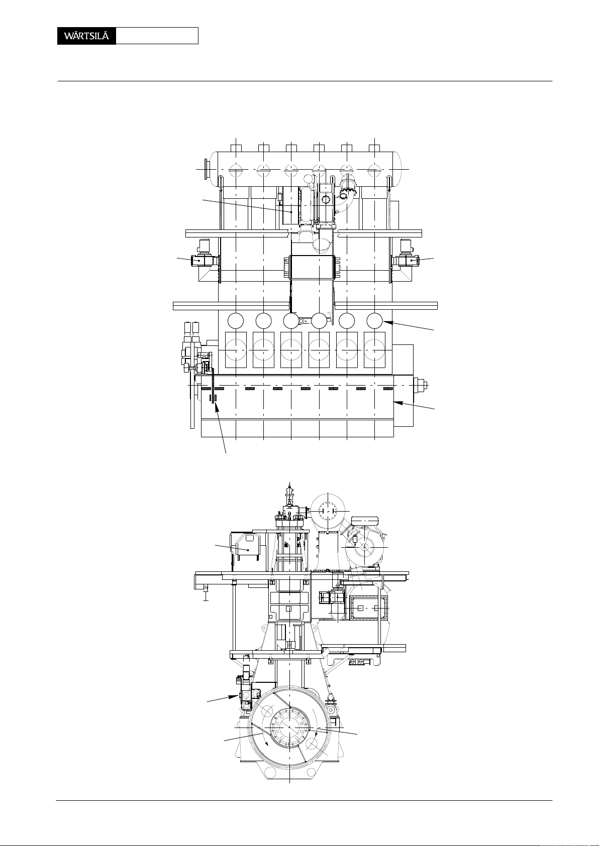
General Arrangement with One Turbocharger:
Turbocharger
Maintenance
0008−1/A1
Auxiliary
Blower 1
DRIVING END
Thrust Bearing Pads
Rail Unit
1 2 3 4 5 6
65432871
Auxiliary
Blower 2
Cylinder
Numbering
FREE END
Main Bearing
Numbering
FUEL SIDE
Wärtsilä Switzerland Ltd
Supply Unit
Counter-clockwise
Rotation
1/ 3
EXHAUST SIDE
Clockwise Rotation
018.748/09
2010
Page 18
E
ngine Numbering and Designations
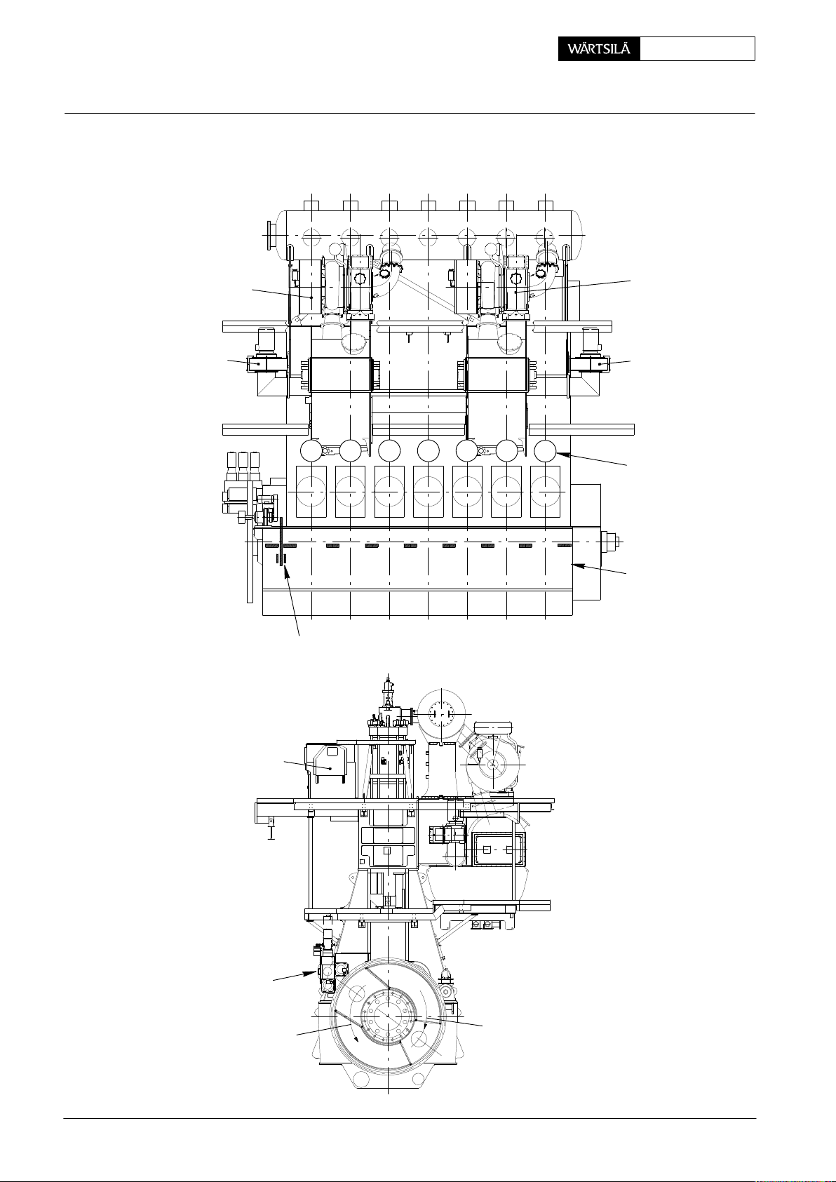
General Arrangement with Two Turbochargers:
Maintenance0008−1/A1 RT-flex50-D
Turbocharger 1
Auxiliary
Blower 1
DRIVING END
Thrust Bearing Pads
1 2 3 4 5 6
65432871
Turbocharger 2
Auxiliary
Blower 2
7
Cylinder
Numbering
FREE END
9
Main Bearing
Numbering
2010
Rail Unit
FUEL SIDE
Supply Unit
Counter-clockwise
Rotation
2/ 3
EXHAUST SIDE
Clockwise Rotation
018.749/09
Wärtsilä Switzerland Ltd
Page 19
RT-flex50-D
E
ngine Numbering and Designations
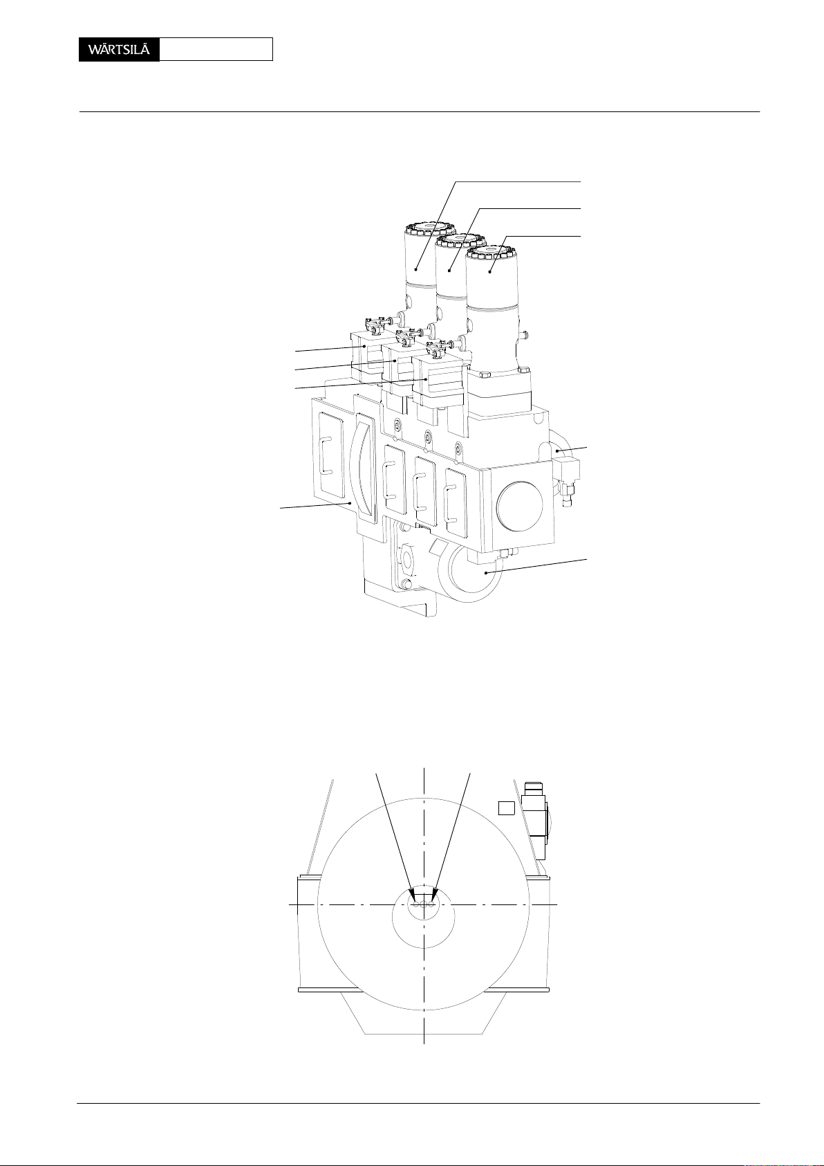
flex Parts:
Fuel Pump Actuator 1
Fuel Pump Actuator 2
Fuel Pump Actuator 3
Maintenance
0008−1/A1
Fuel Pump 1
Fuel Pump 2
Fuel Pump 3
FUEL SIDE
Supply Unit
DRAWN FOR 7 & 8
CYLINDERS
013.149/05
Crank Angle Sensors
Sensor 2
(GT5127C)
Servo Oil Pump 2
Servo Oil Pump 1
DRIVING
END
Sensor 1
(GT5126C)
FUEL SIDE
013.150/05
FREE END
Wärtsilä Switzerland Ltd
3/ 3
2010
Page 20

This page is intentionally left blank
Page 21

RT-flex50-D
G
S
eneral Guidelines for Maintenance
afety Measures and Warnings
Overview
1. General 1/4...............................................
2. General safety precautions 1/4.............................
3. Precautionary measures before beginning of
4. Special safety measures 3/4................................
5. Recommendations for performing work 3/4.................
1. General
The maintenance work which is required to be carried out on the engine at regular
intervals is described in the Maintenance Schedule 0380−1 of this manual and is to
be understood as a general guide. The maintenance intervals are dependent on
the mode of operation, on the power as well as on the quality of the fuel used. Further details are set out in the maintenance schedule.
Experience will show whether the intervals may be extended or need to be shortened.
Strict compliance with the below mentioned recommendations regarding
safety measures and maintenance work is mandatory; the recommendations are not exhaustive.
Maintenance
maintenance work 2/4.....................................
0011−1/A1
2. General safety precautions
D It is the operator’s duty to assure that all personnel is familiar with all safety,
health as well as environment protection rules released for operating and
maintaining a diesel engine plant. In particular greatest attention has to be given to the functioning, handling and dangers of cranes and lifting devices.
D The safety officer has to make sure that all precautions have been taken in
order to avoid dangerous situations.
D The operator has to nominate a person responsible for assigning work tasks
to every person who is participating in maintenance work.
D Make sure that fluids or gases draining or escaping cannot cause accidents,
fires or explosions during maintenance work. Keep the engine and the surroundings clean. Cleanliness increases the quality of the work and helps to
prevent accidents.
Before beginning maintenance work on the diesel engine the corresponding
systems which are influenced by the maintenance work must be relieved of
pressure and/or drained if necessary. A protocol must be established evidencing these activities.
D Certain media, i.e. fuels etc., are highly inflammable, therefore all precaution-
ary measures have to be taken that they do not come into in contact with fires,
glowing or hot parts. Smoking in the engine room is strictly forbidden.
Special attention has to be paid to the rules of fire fighting.
Make absolutely sure that in case of fire alarm no fire extinguishing gases can
be released into the engine room while people are still inside. Emergency escapes are to be marked and personnel is to be instructed of what to do in case
of fire.
Wärtsilä Switzerland Ltd
D Oils and other media can cause slippery surfaces. In order to avoid injury all
surfaces which can be stepped on must be kept clean and dry.
1/ 4
2010
Page 22

Maintenance0011−1/A1 RT-flex50-D
Safety Measures and Warnings
3. Precautionary measures before beginning of maintenance work
Before starting any maintenance work on the engine (particularly on the running
gear), take the following precautionary measures:
⇒ Close the shut-off valves on the starting air bottles.
⇒ Close all the shut-off valves in the control air supply unit, and open the drains
on both air bottles until it is depressurized.
⇒ Close by hand the (automatic) shut-off valve for starting air and open the vent
and drain valve to the main starting air piping on the engine as well as the vent
valves on the shut-off valve for starting air , and leave them in this position until
maintenance work is completed.
⇒ Open all indicator cocks on the cylinder covers and leave them in this position
until maintenance work is completed.
⇒ Engage turning gear (gear pinion must be in engaged position) and lock the
lever (see also 3206−1 and 0750−1 in the Operating Manual).
D Where the engine has been stopped due to overheated running gear or
bearings, wait at least 20 minutes before opening the crankcase doors.
D The crankcase doors must always be locked with all the clamps when-
ever the engine is running, even if this is only for a short time in order to
make temperature checks (e.g. after changing bearings during an overhaul,
etc.).
D In the case of a fire in the engine having been extinguished by means of CO
the spaces affected must be well ventilated before work can be carried out
within them.
Attention! When performing electric welding near or on the engine, electromagnetic fields or peak voltage may occur, which may damage the electronic components of the WECS (W
ärtsilä Engine Control System).
Therefore, prior to performing electric welding in the vicinity of the mentioned components, the following precautions must be taken:
D Stop the engine if it is in operation.
D Power off the electronic system and wait one minute.
D If the welding point is within a radius of two metres from an electronic module
and/or a sensor, disconnect the modules and/or sensors.
D Close the covers of all electric boxes and protect cables, sensors, etc. against
sparking and heat.
,
2
2010
D Shield the check and control units with a conductive material and connect
them to earth.
D Run the welding cable from the welding apparatus directly to the welding point
without any unnecessary loops; also, avoid leading the welding cable parallel
to cables of the electronic control unit.
2/ 4
Wärtsilä Switzerland Ltd
Page 23

RT-flex50-D
Safety Measures and Warnings
4. Special safety measures
D Prior to turning the crankshaft with the turning gear, make sure that no person
D At all times when somebody is inside the engine casing another person must
D The allowed load capacity of the engine room crane, the lifting tools, ropes
Maintenance
is inside the engine and no loose parts, tools or devices can get jammed. Also
bear in mind that the coupled propeller turns too (danger in surroundings).
stand by in order that he can give the necessary aid if something unexpected
happens to the person inside the engine. The person who is inside the engine
casing must be equipped with all safety gears which are required to prevent
suffocation within the limited space and atmospheric conditions. Moreover an
antifall guard must be carried at dangerous places!
and chains must be sufficient for the parts to be lifted (see 0012−1 and
0360−1).
Pay also attention to the weight distribution and attachment of the lifting tackle
in order that the part which must be lifted cannot tip over or crash down!
0011−1/A1
D Sharp edges, mating faces etc. as well as ropes are to be protected by wood-
en pieces, leather or special edge guards which are placed between the part
and the rope or chain.
D Always use gloves, a face shield and wear safety goggles when working with
hydraulic tools.
D For your own safety keep away from under hanging loads, never undersling
hanging parts with your fingers or hands and never embrace lifting ropes with
your hands.
D Removed parts must be secured in the engine room.
D For reasons of safety, openings resulting from removed engine components
must be closed!
Remark: For further instructions see also Safety Precautions and Warnings (General Information) 0210−1 in the Operating Manual.
5. Recommendations for performing work
D Pay attention to Utilization of Working Platform and Ladder 3301−1.
D Carry out all work carefully, observing utmost cleanliness!
D For maintenance work on the engine use the tools and devices intended for
the particular job, which, as a rule, are supplied with the engine (see tool list at
the end of this manual).
Wärtsilä Switzerland Ltd
⇒ Tools and devices must be made ready prior to use, make sure they are in
perfect condition.
⇒ Calibrate gauge tools before using and at periodical intervals.
⇒ Check hydraulic tools periodically for tightness and perfect functioning.
⇒ Protect running faces and sealing faces of removed parts by suitable means
to prevent damages.
3/ 4
2010
Page 24

Safety Measures and Warnings
⇒ Close all openings which form when certain parts are removed e.g. pipes, oil
⇒ Check all repaired, overhauled or replaced parts for perfect functioning before
⇒ Check all pipes which have been removed, for tightness after they are refitted.
⇒ Clearances of moving parts must be checked periodically. Should the maxi-
⇒ Arrange to replace all parts taken from spares stock. When ordering new
D When tightening studs, nuts or screws, take the utmost care not to damage
D Adhere to tightening values wherever they are indicated. Use the specified
Maintenance0011−1/A1 RT-flex50-D
holes etc. to prevent dirt from entering the engine. (This includes also the
pipes which are removed).
starting the engine.
mum permissible values (see Clearance Table 0330−1) have been reached or
even exceeded, these parts must be replaced.
parts refer to the Code Book, mention code numbers and description.
their thread. They must be screwed in by hand until metal to metal contact is
achieved. Always use the specified lubricants on the threads.
lubricant on the threads (see 0352−1 and 0352−2).
D Locking devices of bolts, nuts, etc. must be fitted correctly and secured prop-
erly. Use locking plates and locking wires only once.
D For threads of screws and studs which are getting very hot, (i.e. exhaust pipe
or turbocharger fastenings) apply a high temperature resistant lubricant before assembly, to prevent a heat seizure.
D Used rubber rings must always be replaced by new ones when an overhaul of
any engine component takes place; they must conform in dimension and
quality to the specifications in the 0370−1.
The fitting of piston seal rings and rod seal rings requires the greatest of care
to prevent damage, over expansion or deformation. Before fitting the rings
heat them first in boiling water.
2010
4/ 4
Wärtsilä Switzerland Ltd
Page 25

RT-flex50-D
G
W
eneral Guidelines for Lifting Tools
ire Rope Slings, Span-sets, Eye Bolts, etc.
1. General
The permissible capacities of the engine crane, lifting tools, ropes, chains, lifting
eye bolts, etc. must always correspond with the weights of the parts to be lifted
(see also Masses (Weights) 0360−1).
Remark: The admissible lifting (max. loading) capacity in kg corresponds to the
WLL = W
For fitting and removal of engine components or their transportation, only the tools
which are in perfect condition and intended for this purpose may be used. Ropes
which have begun tearing or otherwise are defective and tools which are damaged
have to be exchanged.
For safe and proper handling of crane, suspension tools or transport of loads we
recommend to proceed as follows for safety reasons:
D Determination of the weight of load
D Determination of the suspension centres and weight distribution
orking Load Limit.
Maintenance
0012−1/A1
2. Attachment elements
2.1 Wire rope slings
2.2 Span-sets
2.3 Eye bolts and eye nuts
D Choice of attachment elements
D Attaching and disconnecting
The lifting capacity of the wire rope slings is listed under their tool number in Tools
List 9403−5.
Span-sets have the advantage of easy and simple handling. The code and the
colour normally indicate the maximum admissible total load. Loops and knots in
the span-sets reduce their lifting capacity by one third.
Only those eye bolts and eye nuts may be used which are in accordance with DIN
580 & 582:2003−08 or which fulfil or exceed these values, including the safety
factor.
All calculations for components and tools where eye bolts and eye nuts are used
are laid out accordingly and based on the mentioned standards.
Wärtsilä Switzerland Ltd
1/ 5
2010
Page 26
Maintenance0012−1/A1 RT-flex50-D
G
eneral Guidelines: Wire Rope Slings, Span-sets, Eye Bolts, etc.
Lifting capacity (for information purposes only):
Eye bolts &
eye nuts,
single-strand double-strand (45°)
Lifting capacity [kg]
thread size
M8 140 100
M10 230 170
M12 340 240
M16 700 500
M20 1200 860
M24 1800 1290
M30 3200 2300
M36 4600 3300
M42 6300 4500
M48 8600 6100
M56 11 500 8300
45
1)
_
Remarks: The details listed in the table above are based on DIN 580 &
582:2003−08, requiring that the eye bolt or the eye nut:
− is completely turned in or screwed down;
− lies flat and fully on the seating surface;
− was checked for visible damages (
1)
−
Full load is only permissible in the direction of the ring, therefore the
eye bolts or eye nuts must be brought to the right position, if necessary by using distance rings.
D If there are through holes, a washer should be placed from the opposite side
under the nut or screw head.
D Whenever possible, do not apply an angle of inclination bigger than 45° (in all
directions with regard to the ring level), and especially avoid lateral pulling!
D For varying use on different objects to be carried, eye nuts or eye bolts with
thread diameters one size higher should be used.
2.4 RUD-eye bolts and RUD-swivel lugs
Only those RUD-eye bolts & RUD-swivel lugs may be used with a safety factor 4.
Manufacturer:
RUD Ketten
Rieger & Dietz GmbH u. Co
Friedensinsel
D−73432 Aalen
Germany
http://www.rud.com
e.g. corrosion, deformation) before using it.
2010
2/ 5
Wärtsilä Switzerland Ltd
Page 27
RT-flex50-D
G
Maintenance
eneral Guidelines: Wire Rope Slings, Span-sets, Eye Bolts, etc.
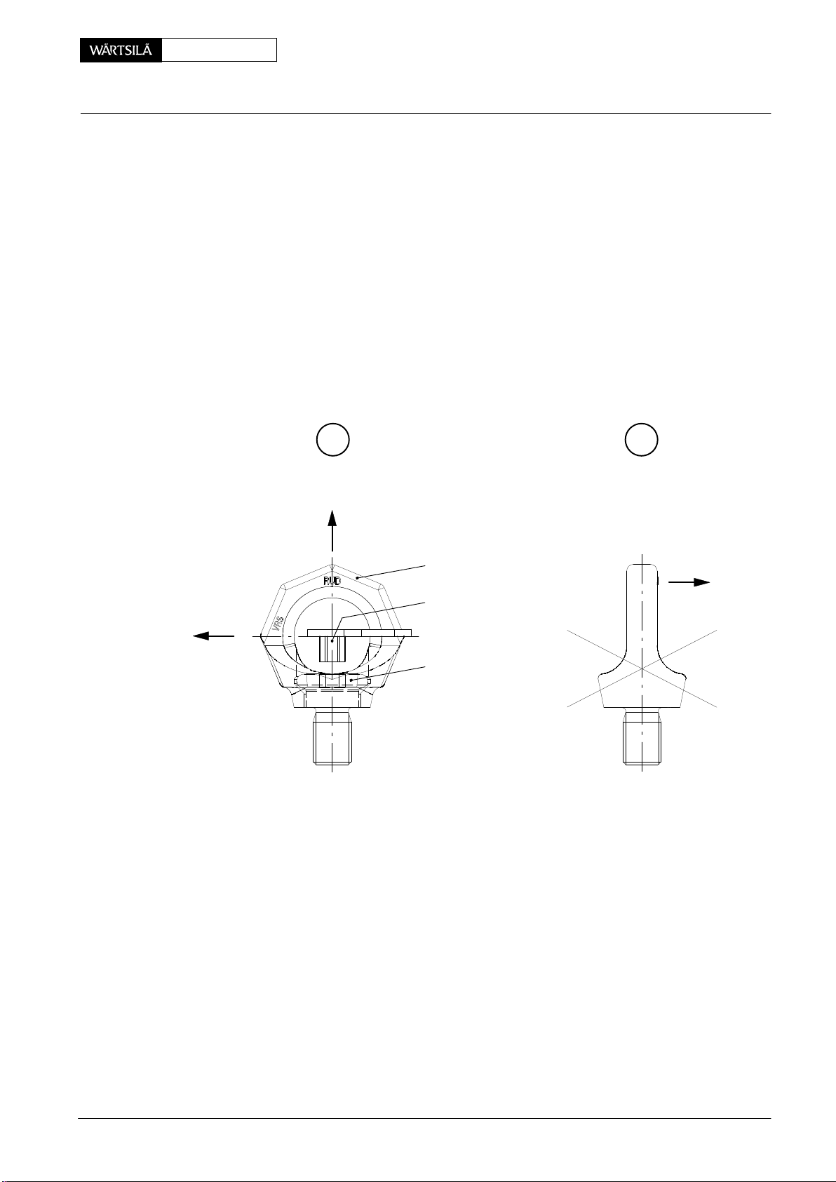
2.4.1 Remarks on the use of RUD-eye bolts
− they must be completely screwed down, lying fully on the seating surfaces.
− they are hand-screwed with their own star-profile wrenches (do not use any
extension).
D In order that after tightening the ring of the RUD-eye bolt is freely rotatable, the
star-profile wrench must be removed from the inner hexagon of the screw as
shown in Fig. ’A’.
D Prior to loading the RUD-eye bolt adjust it in force direction (RUD-eye bolts
are not suitable to be turned under load).
D Lateral loading is permitted in no circumstances! (Fig. ’B’)
0012−1/A1
FORCE
DIRECTION
A
FORCE
DIRECTION
Ring
Star-profile
wrench
Screw
B
FORCE
DIRECTION
013.444/05
Wärtsilä Switzerland Ltd
3/ 5
2010
Page 28
Maintenance0012−1/A1 RT-flex50-D
G
eneral Guidelines: Wire Rope Slings, Span-sets, Eye Bolts, etc.
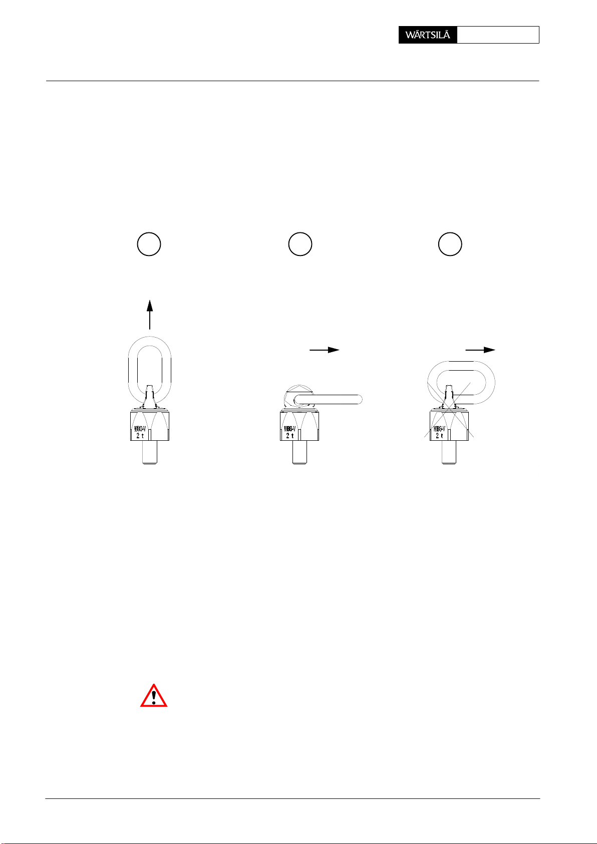
2.4.2 Remarks on the use of RUD-swivel lugs
− they must be completely screwed down, lying fully on the seating surfaces.
− they are hand-screwed with an open end wrench.
D Prior to loading the RUD-swivel lug adjust it in force direction (Fig. ’C’ and ’D’).
D Loading as shown in Fig. ’E’ should be be avoided if possible!
C D E
FORCE
DIRECTION
2.5 Shackles
FORCE
DIRECTION
013.445/05
Only those shackles may be used which are in accordance with American Standard RR−C−271A or which fulfil or exceed these values, including the safety factor .
All calculations for components and tools where shackles are used are laid out accordingly and based on the mentioned standards.
Normally, the permissible lifting capacity of the shackles is specified for one single
strand.
FORCE
DIRECTION
2010
Attention! If tools are combined (e.g. beams with shackles, RUD-eye bolts or
RUD-swivel lugs and ropes, etc.), it is always the weakest element which deter-
mines the maximum lifting capacity (see details in Tools List 9403−5).
4/ 5
Wärtsilä Switzerland Ltd
Page 29

RT-flex50-D
G
Maintenance
eneral Guidelines: Wire Rope Slings, Span-sets, Eye Bolts, etc.
3. Attaching and disconnecting
The following must be observed:
D Distribution of load:
− one strand carries the total of load weight
− two strands carry each one half of the load weight
− four strands carry each one quarter of the load weight if the load is distrib-
uted equally.
D Angle of strand:
− the flatter the strand angle, the more the strand is stressed
− the more acute the strand angle is, the less the strand is stressed.
D Place a soft-wood board between rope and engine component, because the
ropes tend to slide on smooth surfaces (e.g. tubes, shafts).
0012−1/A1
D Protect the ropes against damages by providing a wooden pallet or a rag.
Sharp edges may even cut steel cables!
D If possible always tie down the load. (danger of fall)
D Wrapping the rope twice increases friction and adhesion in such a manner
that even a smooth, oily shaft is sliding less.
D Hemp rope strands, wrapped around the hook, prevent sliding. Do not wrap
steel cables, but cross them instead.
Danger of injuries! For your own safety never stand beneath loads!
Hold the ropes in the flat of your hands and keep your fingers stretched out. Never
seize the load at the bottom, but always lead it laterally. Always put down the loads
on a perfect ground, and use sufficiently sized bases.
Wärtsilä Switzerland Ltd
5/ 5
2010
Page 30

This page is intentionally left blank
Page 31

RT-flex50-D
C
learance Table
Overview
Maintenance
− General 1/25..............................................
− Crankshaft and Thrust Bearing 2, 3/25......................
− Crankshaft and Main Bearing 4, 5/25........................
− Crosshead Guide 6, 7/25...................................
− Cylinder Liner 8, 9/25......................................
− Piston Rod Gland 10, 11/25.................................
− Exhaust Valve 12, 13/25....................................
− Top and Bottom End Bearings to Connecting Rod 14, 15/25...
− Piston Cooling and Crosshead Lubricating Link 16, 17/25.....
− Piston and Piston Rings 18, 19/25...........................
− Driving Wheels for Supply Unit 20, 21/25....................
− Supply Unit 22, 23/25.......................................
− Fuel Pump 24, 25/25........................................
0330−1/A1
1. General
The clearances listed in the column ’Nominal dimension’ of the following table correspond to design and manufacturing values or to the settings on the new engine.
The values listed in the column ’Maximum clearance, dimension’ are such values
as may be reached after a lengthy operating period, which however may not be
allowed to be exceeded or fall below. On components where the clearance is adjustable by modifying the thickness of shims, discs, spacers etc. the value given as
’Normal Clearance’ should always be arrived at, or striven to attain. Where this is
not possible, worn parts must be replaced by standard new ones or reconditioned
by suitable material buildup.
If, during an overhaul, clearances are measured which have almost reached the
permissible limit, it must be left to individual judgement to decide whether a component part should be replaced or remain fitted till the next overhaul. This depends for
example on the duration of the next operation period till the next overhaul and what
wear has to be expected based on experience gained.
Wärtsilä Switzerland Ltd
1/ 25
2010
Page 32

C
learance Table
C
rankshaft and Thrust Bearing
Maintenance0330−1/A1 RT-flex50-D
2
013.025/05
1
2010
2/ 25
Wärtsilä Switzerland Ltd
Page 33

RT-flex50-D
C
C
learance Table
rankshaft and Thrust Bearing
Maintenance
0330−1/A1
1203
1224
Group
Key No.
Description Measuring
direction
(method of
measuring)
Nominal
dimension
(normal, new)
[mm]
Maximum clearance,
Thrust bearing
Thrust bearing pad thickness
67
− 0.5
− 0.6
1 Thrust bearing clearance axial (total) 0.8−1.3 2.5
2 Thrust bearing pad, lateral clearance total 6
dimension
(due to wear)
[mm]
Wärtsilä Switzerland Ltd
3/ 25
2010
Page 34

C
learance Table
C
rankshaft and Main Bearing
Maintenance0330−1/A1 RT-flex50-D
1
MAIN BEARING
No. 1
1
018.600/09
MAIN BEARING No. 2
AND FOLLOWING
2
3
018.663/09
2010 / 50−D
4/ 25
Wärtsilä Switzerland Ltd
Page 35

RT-flex50-D
C
C
learance Table
rankshaft and Main Bearing
Maintenance
0330−1/A1
Description Measuring
Group
Key No.
1132 Main bearing No. 1
Crankshaft outer ∅
Main bearing inner ∅ 600
1 Bearing clearance vertical 0.3−0.6 0.9
1132 Main bearing No. 2 and following
Crankshaft outer ∅
Main bearing inner ∅ 600
1 Bearing clearance vertical 0.2−0.5 0.8
All main bearing clearances are only valid with tie rods and main bearing studs
tightened.
direction
(method of
measuring)
Nominal
dimension
(normal, new)
[mm]
0
600
− 0.07
0
600
− 0.07
Maximum clearance,
dimension
(due to wear)
[mm]
Wärtsilä Switzerland Ltd
5/ 25
50−D / 2010
Page 36

C
learance Table
C
rosshead Guide
Maintenance0330−1/A1 RT-flex50-D
4 HB4HB
x x
5
5
1
2
6
7
3
013.027/05
FUEL SIDE
2010
6/ 25
Wärtsilä Switzerland Ltd
Page 37

RT-flex50-D
C
C
learance Table
rosshead Guide
Maintenance
0330−1/A1
Description Measuring
Group
Key No.
3326 Crosshead guide
1 Guide way (column) transverse 812
2 Guide shoe transverse
3 Guide shoe clearance 0.20−0.90 1.0
4 Guide rail, lateral clearance total 0.80−1.60 2.0
*5 Guide shoe, lateral clearance total 0.10−0.60
6 Guide shoe, bearing pin outer ∅
Guide shoe, bearing bore inner ∅
7 Bearing clearance radial 0.064−0.145 0.25
direction
(method of
measuring)
Nominal
dimension
(normal, new)
[mm]
− 0.20
812
− 0.30
−0
532
− 0.044
+ 0.101
532
0.640
Maximum clearance,
dimension
(due to wear)
[mm]
For measuring of clearances see instructions in 3326−1.
Clearance 3 is only valid with tie rods tightened.
* Clearance 5 refers to spacing between white metal of guide shoe and con-
necting rod and must be measured nearby holding plates ’HB’ which must rest
on crosshead pin at ’x’.
Wärtsilä Switzerland Ltd
7/ 25
2010
Page 38

C
learance Table
C
ylinder Liner
1
2
Maintenance0330−1/A1 RT-flex50-D
3
5
approx. 43 − 75 mm
4
016.555/08
2010
8/ 25
Wärtsilä Switzerland Ltd
Page 39

RT-flex50-D
C
C
learance Table
ylinder Liner
Maintenance
0330−1/A1
Description Measuring
Group
Key No.
2124 Water guide jacket on cylinder
cover
Water guide jacket Ø
1 Clearance total 0.40−0.80
Water guide jacket Ø
2 Clearance total 1.50−1.90
2124 Water guide jacket on cylinder
liner
Water guide jacket Ø 690
3 Clearance total 1.40−1.80
Water guide jacket Ø
direction
(method of
measuring)
Nominal
dimension
(normal, new)
[mm]
+ 0.3
706
+ 0.1
+ 1.40
700
+ 1.20
− 0.20
695
− 0.40
Maximum clearance,
dimension
(due to wear)
[mm]
4 Clearance total 0.40−0.80
2124 Cylinder liner
*5 Cylinder liner bore radial 500 503.50
* Pay attention to measuring point!
Wärtsilä Switzerland Ltd
9/ 25
2010
Page 40

C
learance Table
P
iston Rod Gland
Maintenance0330−1/A1 RT-flex50-D
1
4
1
5
6
2
6
6
6
6
013.225/05
3
2010
10/ 25
Wärtsilä Switzerland Ltd
Page 41

RT-flex50-D
C
P
learance Table
iston Rod Gland
Maintenance
0330−1/A1
Description Measuring
Group
2303 Piston rod gland
Key No.
*1 Ring width radial 31 min. 25
*2 Ring width radial 22 min. 20.20
*3 Ring width radial 5 min. 3.20
4 Ring clearance axial 0.10−0.26 0.50
5 Ring clearance axial 0.05−0.16 0.40
6 Ring clearance axial 0.10−0.17 0.40
Nominal
direction
(method of
measuring)
* Ring wear
The differential value between nominal dimension and max. wear is equal for
all rings, i.e. also for undersize rings.
dimension
(normal, new)
[mm]
Maximum clearance,
dimension
(due to wear)
[mm]
Wärtsilä Switzerland Ltd
11/ 25
2010
Page 42

C
learance Table
E
xhaust Valve
Maintenance0330−1/A1 RT-flex50-D
VALVE SPINDLE
GUIDE BUSH
1
2
3
L = LENGTH
~ 1/3 L ~ 2/3 L
012.999/05
2010
12/ 25
Wärtsilä Switzerland Ltd
Page 43

RT-flex50-D
C
E
learance Table
xhaust Valve
Maintenance
0330−1/A1
Description Measuring
Group
Key No.
2751 Valve spindle
1 Spindle outer ∅
2751 Guide bush
*2 Bore inner ∅
*3 Bore inner ∅
direction
(method of
measuring)
* Pay attention to measuring point!
Nominal
dimension
(normal, new)
[mm]
− 0.14
55
− 0.17
+ 0.03
55
0
+ 0.03
55
0
Maximum clearance,
dimension
(due to wear)
[mm]
54.40
55.35
56.20
Wärtsilä Switzerland Ltd
13/ 25
2010
Page 44

Maintenance0330−1/A1 RT-flex50-D
C
T
learance Table
op and Bottom End Bearings to Connecting Rod
1
2
3
2
10 mm
3
10 mm
5
6
5
60 mm
6
60 mm
4
2010
14/ 25
013.028/05
Wärtsilä Switzerland Ltd
Page 45

RT-flex50-D
C
T
Maintenance
learance Table
op and Bottom End Bearings to Connecting Rod
0330−1/A1
Description Measuring
Group
3303
Key No.
Top end bearing
3326
Crosshead pin outer ∅
Bearing inner ∅ 532
1 Bearing clearance vertical 0.20−0.40 0.60
*2 Lateral clearance total 0.40−0.60
*3 Lateral clearance total 0.20−0.40
3303 Bottom end bearing
Crankshaft outer ∅
Bearing inner ∅ 600
direction
(method of
measuring)
Nominal
dimension
(normal, new)
[mm]
600
0
− 0.04
4
0
− 0.07
532
Maximum clearance,
dimension
(due to wear)
[mm]
4 Bearing clearance vertical 0.30−0.50 0.65
*5 Lateral clearance total 0.20−0.40
*6 Lateral clearance total 0.30−0.50
* Pay attention to measuring point!
For measuring clearances 1 the crank must be in B.D.C.
Wärtsilä Switzerland Ltd
15/ 25
2010
Page 46

C
learance Table
P
iston Cooling and Crosshead Lubrication
Maintenance0330−1/A1 RT-flex50-D
2
1
013.029/05
2011-12
16/ 25
Wärtsilä Switzerland Ltd
Page 47

RT-flex50-D
C
P
learance Table
iston Cooling and Crosshead Lubrication
Maintenance
0330−1/A1
Description Measuring
Group
Key No.
3603 Piston cooling and crosshead
lubrication
Sleeve inner ∅
Sleeve length
1 Radial clearance total 0.30−0.39 0.42
2 Clearance vertical 0.08−0.20 0.25
Inside (telescopic) pipe outer ∅
direction
(method of
measuring)
Nominal
dimension
(normal, new)
[mm]
+ 0.15
56
+ 0.12
− 0.08
115
− 0.10
− 0.18
56
− 0.24
Maximum clearance,
dimension
(due to wear)
[mm]
Wärtsilä Switzerland Ltd
17/ 25
2010
Page 48

C
learance Table
P
iston and Piston Rings
Maintenance0330−1/A1 RT-flex50-D
1
2
9
10
5
6
3
8
7
4
8
C
BA
40
40
l [mm]
16
15
14
13
PISTON RING WIDTH
12
500 501 502 503 504 [mm]
CYLINDER LINER BORE
l
min
l
min N
2010 / 50−D
18/ 25
Wärtsilä Switzerland Ltd
Page 49

RT-flex50-D
C
P
learance Table
iston and Piston Rings
Maintenance
0330−1/A1
Description Measuring
Group
Key No.
3403 Piston crown
1 Crown outer ∅
2 Crown outer ∅
3403
Piston ring grooves
3425
3 Height of the uppermost groove vertical
4 Height of the two lower grooves vertical
5 Groove depth radial 17.50
3425 Piston rings
Ring height vertical
direction
(method of
measuring)
Nominal
dimension
(normal, new)
[mm]
495
497.7
15
15
15
0
− 0.2
0
− 0.2
+ 0.38
+ 0.33
+ 0.33
+ 0.28
0
− 0.03
Maximum clearance,
dimension
(due to wear)
[mm]
6 Ring clearance vertical 0.33−0.41 0.63
7 Ring clearance vertical 0.28−0.36 0.58
*8 Ring width radial
3403 Piston skirt
9 Skirt outer ∅
3403 Piston rod
10 Rod outer ∅
16.5 ± 0.25
for Running-in Coated
(RC) piston ring see
diagram on page 18
499.4
200
−0
− 0.2
− 0.050
− 0.096
min. 497.7
min. 199.30
The ring width at positions A, B and C is the decisive criterion for refitting of used
piston rings.
Used piston rings may be refitted if they will keep within their min. ring width till the
next overhaul (for judging and reusing piston rings see also 3425−1).
* Pay attention to measuring point!
Wärtsilä Switzerland Ltd
19/ 25
50−D / 2010
Page 50

3
C
learance Table
D
riving Wheels for Supply Unit
Maintenance0330−1/A1 RT-flex50-D
2
4
1
5
WCH00139
013.030/05
2010
20/ 25
Wärtsilä Switzerland Ltd
Page 51

RT-flex50-D
C
D
learance Table
riving Wheels for Supply Unit
Maintenance
0330−1/A1
Description Measuring
Group
4103 Intermediate wheel
Key No.
1 Shaft outer ∅ 160
2 Bearing clearance vertical 0.082−0.147 0.25
3 Axial clearance total 0.6−1.1 1.5
4 Tooth backlash 0.20−0.33 0.55
5 Tooth backlash 0.28−0.42 0.65
direction
(method of
measuring)
Nominal
dimension
(normal, new)
[mm]
Maximum clearance,
dimension
(due to wear)
[mm]
Wärtsilä Switzerland Ltd
21/ 25
2010
Page 52

C
learance Table
S
upply Unit
Maintenance0330−1/A1 RT-flex50-D
6
8
5
4
013.031/05
1327
2010
22/ 25
Wärtsilä Switzerland Ltd
Page 53

RT-flex50-D
C
S
learance Table
upply Unit
Maintenance
0330−1/A1
Description Measuring
Group
Key No.
5552 Supply unit
1 Pinion outer ∅
Bearing (fitted) inner ∅
2 Bearing clearance radial 0.085−0.119
3 Axial clearance total 0.25−0.54 0.7
5552 Camshaft unit
4 Cam shaft outer ∅
5 Bearing clearance radial 0.10−0.19
6 Axial clearance total 0.2−0.5 0.7
7 Tooth backlash 0.12−0.22
direction
(method of
measuring)
Nominal
dimension
(normal, new)
[mm]
0
80
− 0.019
+ 0.10
80
+ 0.085
120
0
− 0.022
Maximum clearance,
dimension
(due to wear)
[mm]
*8 Minimum clearance 2
* Minimum clearance between cam and roller with fuel pump cut out.
Wärtsilä Switzerland Ltd
23/ 25
2010
Page 54

C
learance Table
F
uel Pump
Maintenance0330−1/A1 RT-flex50-D
PLUNGER & CYLINDER
A
1
B
3
171 mm 30 mm
C
012.098/04
8
7
2
4
6
5
013.032/05
2010
24/ 25
Wärtsilä Switzerland Ltd
Page 55

RT-flex50-D
C
F
learance Table
uel Pump
Maintenance
0330−1/A1
Group
5556 Fuel pump
5556 Roller guide
Key No.
1 Clearance (plunger / cylinder) A−B radial 0.028−0.030 0.037
Clearance (plunger / cylinder) B−C radial 0.018−0.020 0.027
Guide piston outer ∅ 130
Lower housing inner ∅ 130
2 Clearance radial 0.070−0.125 0.149
3 Piston / lower spring carrier axial 0.02−0.06 0.08
Bush outer ∅ 60
Roller inner ∅ 60
4 Clearance radial 0.06−0.09 0.10
Pin outer ∅ 50
Description Measuring
direction
(method of
measuring)
Nominal
dimension
(normal, new)
[mm]
Maximum clearance,
dimension
(due to wear)
[mm]
Bush inner ∅ 50
5 Clearance radial 0.025−0.08 0.10
Pin outer ∅ 50
Guide piston (bore) inner ∅ 50
6 Clearance radial 0.009−0.050 0.080
7 Axial clearance of bush total 0.2−0.4 0.5
8 Total clearance between guide piston
and roller with pressure discs
axial 0.26−0.54
0.7
Wärtsilä Switzerland Ltd
25/ 25
2010
Page 56

This page is intentionally left blank
Page 57

RT-flex50-D
T
Maintenance
0352−1/A1
ightening Values of Important Screwed Connections
Group Description Thread Tightening values Lubricant
1
1112−1
1132−1
1715−1
1903−1
2
2106 *
2138−1
2708−2
1
[bar]2[Nm]
1
Foundation bolt
(metal and synthetic chocks)
2
Main bearing, nut for waisted stud
3
Engine stay (friction type)
4
Tie rod
(see instructions in 1903−1)
5
Cylinder jacket bolting-up / bolt
*
5
Cylinder jacket bolting-up / fitted bolt
6
Lubricating quill (Pulse Jet), screw
(see instructions in 2138−1)
7
Cylinder cover, nut for waisted stud
M48 1500
1st step 900 bar
nd
step 1500 bar
2
M42
1st step 1000 Nm
nd
step 1500 Nm
2
st
step to 2nd step (20_)
1
M48 310
M72x6 1500
M36
M36
Elongation 0.50± 0.04 mm Oil
Elongation 0.30 ± 0.04 mm Oil
M10x50 10
M56 1500
3
[_(; mm]
(255_)
MOLYKOTE G
Oil
MOLYKOTE G
MOLYKOTE G
Oil
Oil
2722−1
8
Injection valve, screwed connection
with cylinder cover
(see instructions in 2722−1)
9
Injection valve, retaining nut, nozzle
body − nozzle holder
(see instructions in 2722−1 with OBEL test
bench)
2728−1
2745−1
1 When using other hydraulic jacks, required pressure in bar must be calculated in relation to effective jack piston surface!
Conversion factor: 1 Nm = 0.102 mkp 1 bar = 1.02 kp/cm
2 Tightening torque
3 Tightening angle or elongation
− Numbers in
− Values in parentheses (...) are for information only, to be used for comparison.
− Screwed connections must be tightened in accordance with values not in parentheses.
Respective lubricant has to be applied to threads and seating surfaces, if no other instructions are mentioned.
− Bostik Findley Inc. (USA) is manufacturer of Never-Seez NSBT-8.
* Tightening procedure not mentioned in this Manual.
10
Starting valve spindle, nut
(spindle thread not to be lubricated in region
of locking ring)
Starting valve, screw
11
12
Indicator valve, screw
f refer to illustrations on pages 7 to 16.
M12 Equally tighten Allen
screws until spring guides
are flush with spring cages
M60x2
1st step 100 Nm
st
step to 2nd step 30_
1
(loosen retaining nut after initial
assembly and then repeat tightening procedure)
M20 140
M20x150
1st step 80 Nm
st
step to 2nd step 90_
1
M20 80
2
MOLYKOTE G
Never-Seez
NSBT-8
Never-Seez
NSBT-8
Never-Seez
NSBT-8
Never-Seez
NSBT-8
Wärtsilä Switzerland Ltd
1/ 16
50−D / 2011-12
Page 58

Maintenance0352−1/A1 RT-flex50-D
T
ightening Values of Important Screwed Connections
Group Description Thread Tightening values Lubricant
2751−1
2751−2
3
3103 *
3114 *
3130−2 *
3146−1
3303−1
13
Exh. valve cage, nut for waisted stud
14
Exhaust valve, screw for measuring
1
[bar]2[Nm]
M64 1500
M8 35
3
[_(; mm]
(155_)
Oil
Oil
cone − piston
15
Lower − upper housings, nut for
M16 125
Oil
waisted stud
16
Coupling bolt for flywheel
17
Coupling bolt for propeller shaft
18
Crankshaft − vibration damper, nut
M48
M85x4
M85x4
20_
40_
35_
MOLYKOTE G
MOLYKOTE G
MOLYKOTE G
for coupling bolt
*
19
Crankshaft − counterweight, nut for
M85x4
35_
MOLYKOTE G
coupling bolt
20
Axial damper − bedplate, fixing bolt
21
Connecting rod, stud for top end
bearing
Check: 1st step to 2nd step
M24 (540)
M48x5 1500
1st step 1000 bar (gap = 0 mm)
nd
2
step 1500 bar
45_
(15_)
Oil
Oil
M56x6 1500
1st step 950 bar (gap = 0 mm)
nd
2
step 1500 bar
M27x2 1500
(30_)
(80_)
3403−1
Connecting rod, stud for bottom end
22
bearing
Check: 1st step to 2nd step
23
Piston rod − crosshead, nut to
waisted stud
3403−3
24
Piston rod − piston crown, nut to
M27x2 1500
(115_)
waisted stud
25
Spraying plate − piston rod, waisted
screw
M10x90 1
st
step 15 Nm
1st step to 2nd step 40_
no additional
lubricant required
4
4103 *
Intermediate gear bearing − column,
26
waisted bolt
1 When using other hydraulic jacks, required pressure in bar must be calculated in relation to effective jack piston surface!
Conversion factor: 1 Nm = 0.102 mkp 1 bar = 1.02 kp/cm
2 Tightening torque
3 Tightening angle or elongation
− Numbers in
− Values in parentheses (...) are for information only, to be used for comparison.
− Screwed connections must be tightened in accordance with values not in parentheses.
Respective lubricant has to be applied to threads and seating surfaces, if no other instructions are mentioned.
− Bostik Findley Inc. (USA) is manufacturer of Never-Seez NSBT-8.
* Tightening procedure not mentioned in this Manual.
f refer to illustrations on pages 7 to 16.
M30 (1200
2
45_
)
Oil
Oil
Oil
Oil
2010
2/ 16
Wärtsilä Switzerland Ltd
Page 59

RT-flex50-D
T
Maintenance
0352−1/A1
ightening Values of Important Screwed Connections
Group Description Thread Tightening values Lubricant
4103−3
5
5552−2
5552−3
5556−1
5562 *
27
Gear wheel on crankshaft, nut for
waisted bolt to flanged connection
(secured with LOCTITE No. 262)
28
Gear wheel (2-part) on crankshaft
(spare wheel), waisted stud
29
Bearing cover − supply unit, waisted
screw
30
Camshaft − gear wheel, head screw
31
Fuel pump cover − upper housing,
screw
32
Fuel pump − supply unit, screw
33
Fuel pump, bush to lower housing
34
Non-return valve, transition nipple −
fuel rail
1
[bar]2[Nm]
M24x2 (800)
M30x2
Elongation 1.20± 0.06mm
M30 1450
M16 200
M16 115
M24 600
M80x2 200
M36x2 450
3
[_(; mm]
70_
see details in
4103−3
see details in
4103−3
Oil
Oil
Never-Seez
NSBT-8
Oil
see details in
5556−1
Never-Seez
NSBT-8
*
35
Non-return valve, nipple − transition
M36x2 400
nipple
*
36
Non-return valve, screw plug −
M27x2 300
nipple
*
37
Transition nipple
*
38
Pressure transmitter
*
39
Screwed connection to end cover −
M27x2 300
M14x1.5 25
M16 180
fuel rail
*
40
Screwed connection to intermediate
M16 190
piece − fuel rail
5562−1
41
Fuel pressure control valve − inter-
M16 190
mediate piece, screwed connection
1 When using other hydraulic jacks, required pressure in bar must be calculated in relation to effective jack piston surface!
Conversion factor: 1 Nm = 0.102 mkp 1 bar = 1.02 kp/cm
2 Tightening torque
3 Tightening angle or elongation
− Numbers in
− Values in parentheses (...) are for information only, to be used for comparison.
− Screwed connections must be tightened in accordance with values not in parentheses.
Respective lubricant has to be applied to threads and seating surfaces, if no other instructions are mentioned.
− Bostik Findley Inc. (USA) is manufacturer of Never-Seez NSBT-8.
* Tightening procedure not mentioned in this Manual.
f refer to illustrations on pages 7 to 16.
2
Never-Seez
NSBT-8
Never-Seez
NSBT-8
Never-Seez
NSBT-8
Never-Seez
NSBT-8
Never-Seez
NSBT-8
Never-Seez
NSBT-8
Never-Seez
NSBT-8
Wärtsilä Switzerland Ltd
3/ 16
2010
Page 60

Maintenance0352−1/A1 RT-flex50-D
T
ightening Values of Important Screwed Connections
Group Description Thread Tightening values Lubricant
5564−1
5564 *
5610 *
1
[bar]2[Nm]
42
Injection control unit − fuel rail, screw
43
Injection control unit − fuel rail, screw
44
Screw to pre-control valve
45
Filter holder
46
Connecting nipple
47
Fuel quantity sensor − fuel quantity
M16 110
M12 55
M4 2.5
R ¾”
120
M42x2 350
M8 20
housing, screw
*
48
Fuel quantity housing − intermediate
M10 25
flange, screw
*
49
Fuel quantity sensor − fuel quantity
M12 75
housing, screw
50
Pressure transmitter
G¼”
25
3
[_(; mm]
Never-Seez
NSBT-8
Never-Seez
NSBT-8
Never-Seez
NSBT-8
Oil
Never-Seez
NSBT-8
Never-Seez
NSBT-8
Never-Seez
NSBT-8
Never-Seez
NSBT-8
Oil
*
51
Screwed connection to end cover −
M16 160
servo oil rail
M20 200
M16 170
5612−1
52
Drain screw
53
Exhaust valve control unit − servo oil
rail, screw
54
Cover − valve housing, screw
55
Orifice
56
Oil filter
57
Screw to pre-control valve
1 When using other hydraulic jacks, required pressure in bar must be calculated in relation to effective jack piston surface!
Conversion factor: 1 Nm = 0.102 mkp 1 bar = 1.02 kp/cm
2 Tightening torque
3 Tightening angle or elongation
− Numbers in
− Values in parentheses (...) are for information only, to be used for comparison.
− Screwed connections must be tightened in accordance with values not in parentheses.
Respective lubricant has to be applied to threads and seating surfaces, if no other instructions are mentioned.
− Bostik Findley Inc. (USA) is manufacturer of Never-Seez NSBT-8.
* Tightening procedure not mentioned in this Manual.
f refer to illustrations on pages 7 to 16.
M10
M10 10
M33 225
M4 2.5
2
40
Oil
Oil
Oil
Oil
Oil
Oil
Oil
2011-12
4/ 16
Wärtsilä Switzerland Ltd
Page 61

RT-flex50-D
T
Maintenance
0352−1/A1
ightening Values of Important Screwed Connections
Group Description Thread Tightening values Lubricant
8
8447−1
8460−1
8733−1
8752−1
9
9223−1
1
[bar]2[Nm]
58
Screwed connection to servo oil pipe
59
Non-return valve
60
Screwed connection to hydr. pipe
61
Flange − injection valve, screw
62
Fuel pressure piping, screw
*
63
Valve housing − fuel rail, screw
64
Nut to waisted screw
65
Shaft nut
66
Shaft nut
67
Screw to shaft encoder − bearing
M10 & 12 40
G¼”
25
M8x90 20
M10 40
M12 55
M16 150
M16 140
M40x1.5 25
M35x1.5 25
M8 16
3
[_(; mm]
Oil
Oil
Oil
Never-Seez
NSBT-8
Never-Seez
NSBT-8
Never-Seez
NSBT-8
MOLYKOTE G
MOLYKOTE G
MOLYKOTE G
MOLYKOTE G
housing
68
Screw to distance piece
69
Screw to connecting unit − driving
M12 60
M12 60
MOLYKOTE G
MOLYKOTE G
wheel
70
Screw to spring tensioner − coupling
M12 60
MOLYKOTE G
disc
MOLYKOTE G
MOLYKOTE G
9923 *
71
Screw to spring tensioner
72
Connecting unit, adjusting disc −
M10 35
M10 35
coupling disc, screw
9314 *
73
Clamping nut to oil mist detector
*
Screws for opening head of oil mist
74
G ¾”
15
5
detector
1 When using other hydraulic jacks, required pressure in bar must be calculated in relation to effective jack piston surface!
Conversion factor: 1 Nm = 0.102 mkp 1 bar = 1.02 kp/cm
2 Tightening torque
3 Tightening angle or elongation
− Numbers in
− Values in parentheses (...) are for information only, to be used for comparison.
− Screwed connections must be tightened in accordance with values not in parentheses.
Respective lubricant has to be applied to threads and seating surfaces, if no other instructions are mentioned.
− Bostik Findley Inc. (USA) is manufacturer of Never-Seez NSBT-8.
* Tightening procedure not mentioned in this Manual.
f refer to illustrations on pages 7 to 16.
2
Oil
Oil
Wärtsilä Switzerland Ltd
5/ 16
2011-12
Page 62

Maintenance0352−1/A1 RT-flex50-D
)
T
ightening Values of Important Screwed Connections
Group Description Thread Tightening values Lubricant
(2124−2)
1
[bar]2[Nm]
3
[_(; mm]
Tools
75
Lifting gear 94202, screw
(see instructions in 2124−2)
M24 200
no additional
lubricant required
Lifting tool 94559 for supply unit
76
*
*
*
*
*
RUD-eye bolt
77
RUD-eye bolt
78
Screw
79
Screw
80
Blank flanges 94569 / 94569a, screw
(see instructions in Operating Manual 5556−2
M24 190
M36 190
M20 450
M20 450
M12x50 /
80
55
Oil
Oil
Oil
Oil
Never-Seez
NSBT-8
1 When using other hydraulic jacks, required pressure in bar must be calculated in relation to effective jack piston surface!
Conversion factor: 1 Nm = 0.102 mkp 1 bar = 1.02 kp/cm
2 Tightening torque
3 Tightening angle or elongation
− Numbers in
− Values in parentheses (...) are for information only, to be used for comparison.
− Screwed connections must be tightened in accordance with values not in parentheses.
Respective lubricant has to be applied to threads and seating surfaces, if no other instructions are mentioned.
− Bostik Findley Inc. (USA) is manufacturer of Never-Seez NSBT-8.
* Tightening procedure not mentioned in this Manual.
f refer to illustrations on pages 7 to 16.
2010
2
6/ 16
Wärtsilä Switzerland Ltd
Page 63

RT-flex50-D
T
Maintenance
ightening Values of Important Screwed Connections
0352−1/A1
LIFTING GEAR FOR
CYLINDER LINER
013.633/05
ENGINE STAY
(FRICTION TYPE)
75
013.634/05
3
008.570/01
7
6
4
013.636/05
5
21
22
2626
1
016.589/08a
Wärtsilä Switzerland Ltd
7/ 16
50−D / 2010
Page 64

Maintenance0352−1/A1 RT-flex50-D
9
T
ightening Values of Important Screwed Connections
16
2 17
25
24
23
18
1
018.723/09
28
2010 / 50−D
27
8/ 16
20
016.590/08a
Wärtsilä Switzerland Ltd
Page 65

RT-flex50-D
T
ightening Values of Important Screwed Connections
Maintenance
0352−1/A1
60
15
14
11
10
60
13
61
8
7
61
016.591/08
12
Wärtsilä Switzerland Ltd
9/ 16
9
2010
Page 66

Maintenance0352−1/A1 RT-flex50-D
T
ightening Values of Important Screwed Connections
SUPPLY UNIT
31
30
32
33
016.592/08
013.645/05
29
2010
10/ 16
Wärtsilä Switzerland Ltd
Page 67

RT-flex50-D
T
Maintenance
ightening Values of Important Screwed Connections
0352−1/A1
46
45
FUEL RAIL
49 48 47
I
43 44424041
013.647/05
I
39
63
62
II
013.646/05
II
39 34 35 36
013.648/05
37 38
Wärtsilä Switzerland Ltd
11/ 16
2010
Page 68

Maintenance0352−1/A1 RT-flex50-D
T
ightening Values of Important Screwed Connections
63
62
2010
62
12/ 16
013.649/05
Wärtsilä Switzerland Ltd
Page 69

RT-flex50-D
T
Maintenance
ightening Values of Important Screwed Connections
SERVO OIL RAIL
I
51
I
I - I
0352−1/A1
IV
51
WCH00678
52
55
57
56
50
013.651/05
53
IVIII
54
III
WCH00678
Wärtsilä Switzerland Ltd
13/ 16
2011-12
Page 70

Maintenance0352−1/A1 RT-flex50-D
T
ightening Values of Important Screwed Connections
58
I - I
701.013.655
013.655/05
II
58
013.656/05
59
58
013.654/05
2010
14/ 16
Wärtsilä Switzerland Ltd
Page 71

RT-flex50-D
CRANK ANGLE SENSOR UNIT
02
T
Maintenance
ightening Values of Important Screwed Connections
F
I
0352−1/A1
66
008.566/01
69
65
CONNECTING UNIT TO CRANK
ANGLE SENSOR UNIT
G
72
68
64
I - I
I
010.293/
67
71
70
G
008.750/01
008.567/01
Wärtsilä Switzerland Ltd
15/ 16
2010
Page 72

Maintenance0352−1/A1 RT-flex50-D
T
ightening Values of Important Screwed Connections
013.659/05
74
73
76
LIFTING TOOL
FOR RAIL UNIT
016.593/08
ARRANGEMENT OF BLANK
FLANGES 94569 / 94569a
80
77
80
2010
79
013.658/05
78
16/ 16
016.594/08
Wärtsilä Switzerland Ltd
Page 73

RT-flex50-D
T
Maintenance
ightening Values of Standard Screwed Connections
1. Standard screws
This table is valid for all screws that are not considered in 0352−1.
It is recommended to lubricate the threads for screws which come into contact with
hot parts like exhaust pipings, expansion pieces, etc. with a heat-resisting lubricant, e.g. THREAD GARD.
Attention! These tightening instructions are valid only if:
− screws are made of the 8.8 material
− threads have been lubricated with oil
Standard thread Fine thread Tightening torque [Nm]
M8 M8 x 1 20
M10 M10 x 1.25 40
M12 M12 x 1.25 70
M14 M14 x 1.5 110
M16 M16 x 1.5 170
M18 M18 x 1.5 250
M20 M20 x 1.5 350
M22 M22 x 1.5 450
M24 M24 x 2 600
M27 M27 x 2 900
M30 M30 x 2 1200
M33 M33 x 2 1600
M36 M36 x 3 2100
M39 M39 x 3 2500
M42 M42 x 3 2900
M45 M45 x 3 3300
M48 M48 x 3 3700
M52 M52 x 3 4100
M56 M56 x 4 4600
M60 M60 x 4 5200
0352−2/A1
Wärtsilä Switzerland Ltd
1/ 2
2010
Page 74

Maintenance0352−2/A1 RT-flex50-D
0
Tightening Values of Standard Screwed Connections
2. Waisted studs
Waisted studs must be tightened according to the values in the following diagram.
D Before fitting a waisted stud clean its thread and corresponding tap hole. The
sealing faces must be degreased (e.g. using white spirit) and subsequently
primed.
D Screw in the waisted stud without lubricant on the thread right to the bottom of
the tap hole, and tighten. Always utilize a stud driver or two nuts.
Tools like a pipe wrench etc. which would damage the stud shank must never be
used.
D For the protection of the waisted stud in the cylinder block and cylinder cover,
fill the annular space above the thread with a non-hardening jointing compound (see 2751−1).
3500
3000
2500
2000
1500
TIGHTENING TORQUE [Nm]
1000
500
TIGHTENING TORQUE FOR WAISTED STUDS
400
300
200
100
2010
0
10 3020 40 50 60
001.769/97
70 80 100 11090 120
THREAD DIAMETER [mm]
2/ 2
0
10
20 30 40 50 6
Wärtsilä Switzerland Ltd
Page 75

RT-flex50-D
M
I
asses (Weights)
ndividual Components per Piece in kg
Group Component Execution kg
1
1115 Main bearing cover 163
1134 Main bearing shells (upper and lower) 48
1203 Holder for thrust bearing 48
1224 Thrust bearing pad 41
Maintenance
0360−1/A1
1717 Casing, upper part
Casing, lower part
1720 Oil baffle, upper part
Oil baffle, lower part
1730 Bearing housing to supply unit drive 560
1903 Tie rod
Tie rod nut
Intermediate ring
free end
free end
driving end
driving end
M72x6 thread ∅ 210
2
2106 Waisted stud in cylinder block 29
2124 Cylinder liner 2000
2130 Water guide jacket (upper)
Water guide jacket (lower)
2303 Piston rod gland 85
2708 Waisted stud for valve cage
Cylinder cover without accessories
Cylinder cover with valves and water
guide jacket
complete
1097
1762
388
544
190
78
3.3
8.3
58
194
27
Wärtsilä Switzerland Ltd
2722 Injection valve complete 10
2728 Starting valve complete 20
2751 Exhaust valve complete 450
2754 Exhaust valve spindle 41
3
3103 Balance weight on crankshaft 460 ... 575
3122 Flywheel light
heavy
3140 Axial damper cylinder 2-part 408
3303 Connecting rod complete 1390
1/ 3
1530 ... 2030
4200 ... 8160
50−D / 2011-12
Page 76

Individual Components per Piece in kg
Group Component Execution kg
3306 Connecting rod shank 996
Maintenance0360−1/A1 RT-flex50-D
Lower bearing half for bottom end
bearing with studs
3310 Lower bearing shell half for bottom end
bearing
Upper bearing shell half for bottom end
bearing
3312 Bearing cover for top end bearing 151
3315 Bearing shell for top end bearing 39
3326 Crosshead without guide shoes
Crosshead with guide shoes complete
3403 Piston with piston rod and piston rod
gland
Piston crown
Piston skirt
Piston rod
Spraying plate with oil pipe
3603 Inside (telescopic) pipe to piston
cooling and crosshead lubrication
complete 137
16
23
1066
1464
complete 1011
242
39
588
38
19
4
4106 Gear wheel on crankshaft
2-part, complete
4120 Intermediate wheel with bearing pins
and bearings for supply unit
Bearing pair for intermediate wheel
4325 Shut-off valve for starting air 207
complete 315
5
5552 Supply unit with pumps, driving wheels
Servo oil pump
Camshaft with gear wheel
5556 Fuel pump complete 162
5564 Injection control unit complete 102
5612 Exhaust valve drive complete 29
complete
5−6 Cyl. engines
7−8 Cyl. engines
5−6 Cyl. engines
7−8 Cyl. engines
1750
2000
375
579
51
150
168
189
2011-12 / 50−D
2/ 3
Wärtsilä Switzerland Ltd
Page 77

RT-flex50-D
Individual Components per Piece in kg
Group Component Execution kg
6
Maintenance
0360−1/A1
6506 Exhaust gas turbocharger ABB−A175 compl.
ABB−A170 compl.
MET60A complete
6545 Auxiliary blower with electric motor
Electric motor
6606 Scavenge air cooler SAC261
6708 Water separator 215 ... 330
6735 Scavenge air waste gate (with silencer)
Silencer
complete 591 ... 885
SAC265
SAC285
4900
3000
4260
160 ... 194
1650
2100
950
135
35
Wärtsilä Switzerland Ltd
3/ 3
50−D / 2011-12
Page 78

This page is intentionally left blank
Page 79

RT-flex50-D
D
O
imensions
-rings and Round Rubber Rings
Maintenance
0370−1/A1
Group Place of application Thick-
ness
[mm]
1903 Tie rod 5.33 91.44
2106 Cylinder block 9 550
Cylinder liner
2124
2130
2136
2138
2303
2708 Cylinder cover − water guide jacket 9 660
2728
2751
3130
3403
4325
Cylinder liner − water guide jacket
Water guide jacket
Connection piece − water guide jacket
Transition tube 5.33 37.47
Lubricating quill (bush)
Lubricating quill (bush) (Pulse Feed Lubrication)
Piston rod gland
Housing − cylinder block
Starting valve
Starting valve − cylinder cover 5.33 85.09
Cover − housing 3.53 91.67
Cover − solenoid valve 2 10
Exhaust valve
Valve cage − cylinder cover
Valve seat − cylinder cover 6.99 329.57
Guide bush − valve cage 5.33 75.57
Lower housing − valve cage 6.99 148.59
Valve seat − valve cage 7 250
Piston − valve spindle 5.33 53.34
Transmitter − lower housing 3.53 28.17
Lower housing − upper housing 6.99 164.47
Vibration damper on crankshaft
Intermediate flange − vibration damper
Piston
Piston − oil pipe 5.33 85.09
Piston crown − spraying plate 6.99 266.07
Piston rod − spraying plate 6.99 253.37
Starting air shut-off valve
Bush for starting air housing − cover
Housing − shut-off valve guide 6.99 170.82
Housing − valve block 3.53 56.74
Valve block − housing 2.62 13.94
Pressure switch − valve block 1.78 6.07
Valve block − double check valve 2 10
9 660
5.33 62.87
3.53
3.53
6.99 417.96
6.99 380.37
9 630
6.99 148.59
Inner ∅
[mm]
36.09
36.09
Wärtsilä Switzerland Ltd
4605
Control air supply unit
Pressure reducing valve − corner union
Valve body − pressure transmitter 1.78 6.86
A
2.4 20.30
1/ 3
2010
Page 80

Maintenance0370−1/A1 RT-flex50-D
Dimensions: O-rings and Round Rubber Rings
Group Place of application Thick-
ness
[mm]
Supply unit
5552
Spray nozzle − housing
2.62 9.92
Fuel pump
5556
Lower housing − housing of supply unit 6.99 158.12
Upper housing − lower housing 6.99 158.12
Valve block − upper housing 5.33 110.49
Valve block − pump cover 5.33 110.49
Pin in guide piston − lower spring carrier 2.62 48.90
Fuel rail
5562
Connection sleeve − heating pipe
5.33 46.99
5.33 32.69
Fuel pressure control valve
Cover − valve body
2.62 113.97
Cover − valve body 2.62 64.77
Cover − valve body 2.62 61.60
Piston − cover 2.62 18.72
Piston − cover 2.62 15.54
Cover − cylinder 1.78 20.35
Spring carrier − valve housing 3.53 18.64
3/2-way solenoid valve − valve body 2 10
Valve tip − piston 1.78 6.07
Valve body − cover 1.78 6.07
Slide valve − valve body 2.62 3.63
Intermediate ring − intermediate piece 3.53 50.39
Intermediate ring − fuel pressure control valve 3.53 32.92
Fuel overpressure safety valve − intermediate piece 3.53 66.27
Fuel overpressure safety valve − interm. p. (back-up
1.4 69.60
ring)
Inner ∅
[mm]
2010
Injection control unit
5564
Fuel quantity piston housing 3.53 40.87
Intermediate ring − housing 2.62 48.90
Pre-control valve − housing 1.78 5.28
Servo oil rail
5610
Valve housing − servo oil rail 3.53 32.92
Exhaust valve control unit − servo oil rail 3.53 32.92
Exhaust valve control unit − connecting block 3.53 47.22
Connecting piece − servo oil rail 2.62 37.77
Non-return valve 2.5 25
Exhaust valve control unit
5612
Cover − spring housing
2.62 48.90
Pre-control valve − valve control block 1.78 5.28
6708 Water separator (round rubber cord) 12
12
2/ 3
2840
3690
Wärtsilä Switzerland Ltd
Page 81

RT-flex50-D
Maintenance
Dimensions: O-rings and Round Rubber Rings
0370−1/A1
Group Place of application Thick-
ness
[mm]
Scavenge air waste gate
6735
8310 Cylinder cooling water piping − outlet orifice 5.33 120.02
8447
8460
8704 Fuel pressure retaining valve 2.62 15.54
8733
3/2-way valve − solenoid valve
Servo oil piping
Connecting block − servo oil pump
Flange − HP piping 5.33 40.64
Flange − HP piping (star tube) 5.33 40.64
Intermediate piece − flange 5.33 50.17
Hydraulic piping − exhaust valve
Exhaust valve control unit − HP piping 5.33 50.17
HP piping − exhaust valve 5.33 50.17
Flange − HP piping 5.33 40.64
Flange − HP piping (star tube) 5.33 37.47
Fuel pressure piping − injection valve
Flange − injection control unit
Flange − injection valve 2.62 32.99
Flange − HP piping 2.62 28.24
Flange − HP piping (star tube) 2.62 25.07
1.78 12.42
2.62 37.77
2.62 32.99
Inner ∅
[mm]
8752
9223
9258
Fuel pressure piping
Fuel pump − flange 2.62 42.52
Flange − HP piping 2.62 42.52
Flange − HP piping (star tube) 2.62 37.77
Intermediate ring − valve housing 2.62 47.29
Crank angle sensor drive
Retaining ring − housing
Measuring instruments
Pressure switch and transmitter
Tools
94345d: Cover plate to cylinder block with piston
removed
94349: Pressure testing device for piston 6.99 215.27
94430: Device for cutting out of a fuel pump 2.62 20.29
94569: Blank flange to fuel pump 2.62 42.52
3.53 72.62
1.78 6.07
6.99 417.96
Wärtsilä Switzerland Ltd
3/ 3
50−D / 2010
Page 82

This page is intentionally left blank
Page 83

RT-flex50-D
Piston Seal Ring (PSR)
Rod Seal Ring (RSR)
D
P
imensions
iston and Rod Seal Rings
Maintenance
0370−2/A1
Seal ring
Group Place of application Ring
4325 Shut-off valve for starting air − valve
Shut-off valve for starting air − spindle
5556 Regulating (toothed) rack − flange RSR 24 x 26 x 1.8
6735 Scavenge air waste gate − piston PSR 140 x 135 x 3.8
Nominal dimension o∅ x i∅ x b
Cylinder
b
type
PSR
RSR
Nominal dimension i∅ x o∅ x b
Bush
Dimension [mm]
160 x 155 x 3.8
30 x 33 x 2.8
O-ring
Seal ring
O-ring
Piston
Rod
i∅ o∅
b
i∅ o∅
Wärtsilä Switzerland Ltd
1/ 3
2010
Page 84

D
imensions: Un-slotted Back-up Rings
Maintenance0370−2/A1 RT-flex50-D
Tool
No.
94114 Waisted studs to main bearing piston
94145 Foundation bolts and engine stays piston
94180 Tie rods (with M100x6 thread diameter) piston
94180a Tie rods (with M72x6 thread diameter) piston
94215a Cylinder cover waisted studs piston
94252 Waisted studs to exhaust valve piston
94314 Waisted studs to bottom end bearing piston
94315 Waisted studs to top end bearing piston
94340 Waisted studs of piston rod − screw
94346 Waisted studs to piston crown piston
Place of application of pre-tensioning
jack
connection
Part Back-up ring
cylinder
cylinder
cylinder
cylinder
cylinder
cylinder
cylinder
cylinder
piston
cylinder
cylinder
(un-slotted)
Dimension [mm]
o∅ x i∅ x t i∅ x s
74 x 67.8 x 1.4
61.2 x 55 x 1.4
92 x 82.6 x 1.7
79.2 x 73 x 1.4
191 x 178.8 x 2.5
162.2 x 150 x 2.5
153 x 140.8 x 2.5
91 x 81.6 x 1.7
110 x 100.6 x 1.7
93.4 x 84 x 1.7
152 x 138.8 x 2.5
105.4 x 96 x 1.7
115 x 105.6 x 1.7
94.4 x 85 x 1.7
105 x 95.6 x 1.7
76.2 x 70 x 1.4
58 x 51.8 x 1.4
47.2 x 41 x 1.4
50.5 x 44.3 x 1.4
46.2 x 40 x 1.4
177.17 x 6.99
148.59 x 6.99
139.07 x 5.33
135.89 x 6.99
104.14 x 5.33
O-ring
66.27 x 3.53
53.57 x 3.53
81.92 x 5.33
72.62 x 3.53
97.79 x 5.33
97.79 x 5.33
85.09 x 5.33
94.62 x 5.33
85.09 x 5.33
94.62 x 5.33
69.44 x 3.53
50.39 x 3.53
40.87 x 3.53
44.04 x 3.53
40.87 x 3.53
Material specification:
i∅o∅
− PC thermoplast: Standard for un-slotted back-up rings
− Nitrile NBR 90: Standard for O-rings
1) Nitrile NBR 70 Sh for O-rings
O-ring
s
Back-up ring
t
i∅o∅
2011-12
2/ 3
Wärtsilä Switzerland Ltd
Page 85

RT-flex50-D
D
imensions: Piston Seal Rings
Maintenance
0370−2/A1
Group Place of application Ring
type
2751 Exhaust valve piston PSR 108 x 92.5 x 6.3
Piston Seal Ring (PSR)
Nominal dimension da x di x b)
Dimension [mm]
Cylinder
Seal ring
O-ring
b
Piston
da = Cylinder diameter
di = Groove diameter
b = Groove width
ddi
a
Wärtsilä Switzerland Ltd
3/ 3
2010
Page 86

This page is intentionally left blank
Page 87

RT-flex50-D
M
I
Maintenance
aintenance Schedule
nspection and Overhaul Intervals (Guidelines)
Group Component Work to be carried out Intervals
0
Lubricating oil − Laboratory analysis 3000 Op. h (operating
hours)
0380−1/A1
Cooling water − Determine quality, concentration of inhibitor and
pH value
(follow instructions of inhibitor manufacturer)
weekly
1
1112−1 Bedplate − Check pre-tension of foundation bolts,
first time after 1500 Op. h
Crankcase − Visual examination
100 Op. h after overhaul works
1132−2 Main bearing − Remove bearing upper half for inspection,
random inspection every 12 000 Op. h
− Remove bottom bearing shell for inspection acc. to class. society
1203−1 Thrust bearing − Check axial and radial clearances 6000−8000 Op. h
− Check bottom drain for free passage 6000−8000 Op. h
1224−1 − Remove thrust bearing pads for inspection acc. to class. society
1715−1 Engine stays with
friction shims
1903−1 Tie rod − Check pre-tension, if necessary re-tension
− Check pre-tension of waisted studs,
first time after sea trial
first time after one year
12 000 Op. h
1500−3000 Op. h
according to
classification society
6000−8000 Op. h
24 000−30 000 Op. h
2
2124−1 Cylinder liner − Establish wear in bore (in fitted condition) at every piston removal
2124−2 − Remove cylinder liner as required
− Replace O-rings at every removal
− Replace (soft iron) joint ring between cylinder liner
and cylinder cover
− Water guide jacket, replace O-rings at every piston removal
− Check condition of antipolishing ring at every piston removal
2124−3 − Grind off wear ridge in bore at every piston removal
− Refinish lubricating grooves as required
− Clean scavenge ports and refinish their edges as required
at every piston removal
Wärtsilä Switzerland Ltd
1/ 7
50−D / 2010
Page 88

Maintenance0380−1/A1 RT-flex50-D
I
nspection and Overhaul Intervals (Guidelines)
Group Component Work to be carried out Intervals
2138−1 Lubricating quill
(pulse lubrication)
− Check function and tightness
− Check function of non-return valves
− Replace O-rings
at every piston removal
at every liner removal
at every liner removal
2303−1 Piston rod gland − Clean rings, establish wear at every piston removal
2708−1 Cylinder cover − Check combustion space for damage and wear at every piston removal
2722−1 Injection valve − Check externally for tightness before starting engine
after a longer standstill
− Check spray pattern, opening pressure, tightness
3000 Op. h
condition of nozzle tip, readjust opening pressure
(life time of nozzle tip about 6000 Op. h)
2728−1 Starting valve − Check piping before the valve during operation,
weekly
if piping is too hot, dismantle starting valve
− Remove and dismantle one starting valve at
6000−8000 Op. h
random. From its condition determine time of
overhaul for remaining valves
− Solenoid valve, random check
overhaul
2751−1toExhaust valve − General inspection of valve housing, valve
6000 Op. h
18 000 Op. h
at every piston removal
spindle and valve seat
(without dismantling of exhaust valve)
2751−4 − Check condition and wear of valve spindle
(if necessary regrind seat by machining)
− Check piston seal ring / air spring & rod seal ring /
guide bush
− Check condition and wear of valve seat
(if necessary regrind seat by machining)
− Random check of valve drive, outside and
inside pistons, damper, thrust piece
− Random check of screwed connection to
measuring cone
3
3103−1 Crankshaft − Measure crank deflection
(always in case of grounding of the ship as well as
before and after every docking)
3130−1 Torsional
vibration damper
3130−2 − Inspection interval and dismantling of vibration
− Take a silicon oil sample from viscous vibration
st
damper (based on results of 1
sample, interval
for taking further samples will be decided)
damper
24 000−36 000 Op. h
24 000−36 000 Op. h
24 000−36 000 Op. h
18 000 Op. h
18 000 Op. h
6000−8000 Op. h
first time after 15 000 −
18 000 Op. h
acc. to instructions of
damper manufacturer
3146−1 Axial damper − Dismantling and inspection 36 000−48 000 Op. h
2010
2/ 7
Wärtsilä Switzerland Ltd
Page 89

RT-flex50-D
I
Maintenance
0380−1/A1
nspection and Overhaul Intervals (Guidelines)
Group Component Work to be carried out Intervals
3206−1 Turning gear − Inspection interval of turning gear acc. to instructions of
turn. gear manufacturer
− Re-lubrication of tooth flanks of pinion & flywheel,
depending on visual inspections, however every
2000 Op. h of diesel engine
− Check screwed connections,
first time after one year (if necessary retighten)
Connecting rod
bearings
3303−2 − Inspect bottom end bearing
3303−3 − Inspect top end bearing 30 000−36 000 Op. h or
3326−1 Guide shoe,
crosshead pin
3326−2 − Remove crosshead as required
3403−1 Piston − Remove, clean and measure ring grooves
3403−3 − Dismantling and assembling (open cooling space
− Check bearing clearances (see 0330−1) 6000−8000 Op. h
(life time of shell 60 000−72 000 Op. h)
− Check clearances 6000−8000 Op. h
(cylinder liner with antipolishing ring and chromeceramic uppermost piston ring)
− Check tightness on piston in situ and with running
oil pump, visual check through scavenge ports
& clean same, min. one piston every three years)
12 000 Op. h
30 000−36 000 Op. h or
acc. to class. society
acc. to class. society
18 000−20 000 Op. h
after refitting
as required
3403−4 − Check condition of the piston top surface at every piston removal
− Visual check through scavenge ports to piston,
piston rings and cylinder liner
(rotate crankshaft with turning gear)
Piston underside − Check condition of space and clean it as required 1500−3000 Op. h
− Check drains for free passage 1500−3000 Op. h
3425−1 Piston rings − Replace all piston rings
If piston is pulled out before overhaul interval, remove and clean piston rings only if necessary and
measure wear rate (i.e. due to high groove wear),
otherwise do not remove piston rings and clean
ring gaps only
1500−3000 Op. h
18 000−20 000 Op. h
4
Start interlock − Check electric and pneumatic interlocks
(see Operating Manual 4003−1)
4103−1 Driving wheels − Check condition of teeth 6000−8000 Op. h
− Check running clearance and backlash of teeth 6000−8000 Op. h
quarterly
Wärtsilä Switzerland Ltd
3/ 7
2010
Page 90

Maintenance0380−1/A1 RT-flex50-D
I
nspection and Overhaul Intervals (Guidelines)
Group Component Work to be carried out Intervals
Starting air
shut-off valve
4325−1 − Dismantle, clean and check
Control air filter − Drain filter
− Vent after each manoeuvring
(particularly seat, springs and seal rings)
− Overhaul common start valve
− Clean filter
5
5552−1 Supply unit − Replace servo oil pump either with new one or a
pump overhauled by a Wärtsilä workshop
− Check pinion and driving wheels to servo oil
pump drive
− Check bearing bushes to pinion 24 000 Op. h
5552−2 − Camshaft, check running surface of cams,
rollers & roller guides (first time after 500 Op. h)
− Camshaft, check bearing clearances at random 12 000 Op. h
− Camshaft, check thrust bearing clearances 36 000 Op. h
period
24 000−36 000 Op. h
18 000 Op. h
weekly
6000 Op. h
24 000 Op. h
3000 Op. h
3000 Op. h
5556−1 Fuel pump − Replace O-rings in valve block 18 000 Op. h
5562−1 Fuel pressure
control valve
(PCV)
5562−2 Fuel
overpressure
safety valve
5564−1 Injection control
unit
Servo oil rail − Replace hoses 18 000−30 000 Op. h
− Random visual check of plunger & cylinder,
roller and roller guide
− Check shut-down function
(see Operating Manual 4003−1)
− Function check
(see Operating Manual 5562−1)
− General overhaul only necessary when
− Replace oil filter 18 000 Op. h
− Function check on test bench 18 000 Op. h
− Replace unit (incl. rail valves) either with new
one or a unit overhauled by a Wärtsilä
− Replace filter 18 000 Op. h
workshop
18 000 Op. h
3000 Op. h
6000 Op. h
PCV fails
24 000−36 000 Op. h
5610−1 Pressure
reducing valve
2012-07
− Checking gas (nitrogen) pre-charge pressure:
the same criteria apply as specified for 7218−1
4/ 7
Wärtsilä Switzerland Ltd
Page 91

RT-flex50-D
I
Maintenance
nspection and Overhaul Intervals (Guidelines)
Group Component Work to be carried out Intervals
0380−1/A1
5612−1 Exhaust valve
control unit
5801−1 Regulating
linkage
6
6420−1 Scavenge air
receiver
Exhaust gas
turbocharger
Air filter − Check filter half yearly
− Random check of piston and slide rod 18 000 Op. h
− Replace rail valve (pre-control valve) 30 000−36 000 Op. h
− Replace filter 18 000 Op. h
− Check for free movement, lubricate movable
parts
− Check and clean air flaps 4000−6000 Op. h
− Clean receiver 4000−6000 Op. h
− Check water drain pipings for free passage 1500−3000 Op. h
− Wash-cleaning of blower in service (see Operating Manual)
− Wash-cleaning or dry cleaning of turbine in
service
− Cleaning of filter at a np increase of 50%
compared to the shop test value at same engine
load
(see Operating Manual 6510−1)
3000 Op. h
(see Operating Manual)
as required
6545−1 Auxiliary blower − Clean impeller and casing 24 000−36 000 Op. h
− Replace ball bearing 24 000−36 000 Op. h
6606−1 Scavenge air
cooler
− Cleaning of scavenge air cooler (air side) in
service at the beginning weekly, later if np
(pressure drop through SAC) increases
compared to the shop test value at same engine
load
(see Operating Manual 6606−1)
− Check condensate collector through sight glass
(see Operating Manual 8345−1)
− Check condensate collector for free passage
(see Operating Manual 8345−1)
− Check scavenge air cooler sealing quarterly
− Vent daily
− Remove scavenge air cooler for general overhaul as required
as required
daily
1500−3000 Op. h
Wärtsilä Switzerland Ltd
5/ 7
2010
Page 92

Maintenance0380−1/A1 RT-flex50-D
I
nspection and Overhaul Intervals (Guidelines)
Group Component Work to be carried out Intervals
6708−1 Water separator − Check condensate collector through sight glass
(see Operating Manual 8345−1)
− Check condensate collector for free passage
(see Operating Manual 8345−1)
− Check water separator elements (if necessary
clean them)
− Remove water separator for general overhaul as required
7
Cylinder
lubricating pump
7218−1 Lubricating pump
and accumulator
(Pulse lubrication)
− Drain and wash out housing,
first time after 1000 Op. h
− General maintenance works according to instructions
− Checking gas (nitrogen) pre-charge pressure:
CLU4−C min. 30 bar / max. 35 bar
directly after installation of a new accumulator −>
then at least once in first week after start-up −>
afterwards −>
daily
1500−3000 Op. h
1500−3000 Op. h
18 000−24 000 Op. h
according to instruction
of pump manufacturer
of equipment
manufacturer
every three months
8
Servo oil
automatic filter
Starting air
piping
Pressure gauges
and pyrometers
Fuel and
lubricating oil
filters
Pipe holders − Check tightness of fastenings periodically, if
8733−1 Fuel pressure
piping (on
cylinder cover)
Non-return valve − Random check 18 000 Op.h
8752−1 Fuel pressure
piping
− Follow manufacturer’s instructions
− Drain (de-water) before and after every
manoeuvring period
− Compare and calibrate according to master
instruments
− Clean or replace filter elements
(depending on make, follow manufacturer’s instructions)
necessary retighten screws
(first time after 100 Op.h, then half yearly)
− Regrind sealing faces as required
− Regrind sealing faces as required
6000−8000 Op.h
as required
as required
2011-12
6/ 7
Wärtsilä Switzerland Ltd
Page 93

RT-flex50-D
I
Maintenance
nspection and Overhaul Intervals (Guidelines)
Group Component Work to be carried out Intervals
9
0380−1/A1
9223−1 Crank angle
sensor unit
Oil mist detector − Follow manufacturer’s instructions half yearly
WECS electronic
components
− Check tension visually
Check cracks and wear of tooted belt visually
Visual lubricating oil check
− Replace toothed belt 24 000 Op.h
− Overhaul drive (ball bearing, sealing ring etc.)
and check shaft eccentricity of CAS drive
− Check shaft eccentricity of CAS drive at every CAS exchange
− Replace crank angle sensor 48 000 Op.h
− Replace FCM−20 module
(see Operating Manual 4002−4)
− Visual cabling check quarterly
The indicated maintenance intervals must be taken as guidance and may vary
depending on the installation. The proper intervals are subject to the points mentioned below. Experience will show whether these intervals can be extended or
must be shortened.
3000 Op.h
48 000 Op.h
(only if new soft belt is
applied from beginning)
36 000−50 000 Op. h
− Environmental and operating conditions
− Heavy fuel oil and lubricating oil qualities (see OM 0710−1 and 0750−1)
− Engine load
− Fuel, lubricating oil and cooling water care (see OM 0720−1 and 0760−1)
− Overhaul according to Maintenance Manual
− Genuine spare parts used
− Engine monitoring
− Engines according to specifications of Wärtsilä Switzerland Ltd.
On the engine sectional drawings 0803−1, those parts are marked with group
numbers, as they are found in the Maintenance Manual.
Engine Control System WECS
Control works in the WECS (Wärtsilä Engine Control System) are described in the
following groups of the Operating Manual:
− Regular checks and recommendations 4002−4......................
− Engine control 4003−1............................................
Wärtsilä Switzerland Ltd
7/ 7
2012-07
Page 94

This page is intentionally left blank
Page 95

RT-flex50-D
5
E
Maintenance
ngine Cross Section and Longitudinal Section
Cross section:
8460−1
8733−1
2728−1
5562−1
5612−1
0803−1/A1
5564−1
3603−1
8447−1
3326−1
3326−2
8752−1
5556−1
5801−1
552−1 to
5552−5
6606−1
6708−1
6420−1
3301−1
3206−1
4103−1
1112−1
WCH00123
Wärtsilä Switzerland Ltd
1/ 2
Pulse Jet / 2010
Page 96

Maintenance0803−1/A1 RT-flex50-D
E
ngine Cross Section and Longitudinal Section
Longitudinal section:
2751−1 to
2751−4
2722−1
2124−1 to
2124−3
2138−1
4325−1
2303−1
2708−1 to
2708−3
3425−1
3403−1 to
3403−4
1903−1
1132−1
1132−2
1203−1
1224−1
4103−3
3303−1 to
3303−5
3146−1
9223−1
3130−1
3130−2
WCH00126
2010 / Pulse Jet
2/ 2
Wärtsilä Switzerland Ltd
Page 97

RT-flex50-D
1
Maintenance
Group1
Bedplate and Tie Rod Group
Bedplate and Thrust Bearing: Checking the Foundation Bolts 1112−1/A1................
o Main Bearing
− Loosening and Tensioning of Waisted Studs 1132−1/A1.............................
− Removal and Fitting of a Main Bearing 1132−2/A1.................................
o Thrust Bearing
− Checking the Axial Clearance 1203−1/A1.........................................
− Removal and Fitting the Thrust Bearing Pads 1224−1/A1............................
Engine Stays with Friction Shims: Checking the Pre-tension 1715−1/A1..................
Tie Rod: Checking the Pre-tension and Tensioning the Tie Rods (M72x6) 1903−1/A2......
Wärtsilä Switzerland Ltd RT−flex50−D / MM / 2011-12
Wärtsilä Switzerland Ltd
1/ 3
Page 98

This page is intentionally left blank
Page 99

RT-flex50-D
B
C
Maintenance
1112−1/A1
edplate and Thrust Bearing
hecking the Foundation Bolts
Tools: Key to Illustrations:
1 Feeler gauge 94122 1 Vent screw 11 Nut
1 Pre-tensioning jack 94145 2 Cylinder 12 Conical socket
1 HP oil pump 94931 3 Piston 13 Seating washer
2 Hydr. distributors 94934a 4 Nut
1 HP hose 94935 5 Bedplate
6 Foundation bolt BN Limiting groove
7 Foundation fitted stud EV Relief valve
8 Sleeve KO Slot
9 Chock RS Round bar
10 Ship’s foundation plate SA Gap
1. General
The pre-tension of the foundation bolts (holding down studs) must be checked at
longer intervals e.g. during overhauls (see 0380−1).
In the area of the thrust bearing the foundation may be fastened with foundation
bolts 6 and sleeves 8 (Fig. ’A’) or with foundation fitted studs 7 (Fig. ’B’).
The remaining area is fastened with foundation bolts 6, however without sleeves 8
(Fig. ’C’).
Remark: Pay attention to the General Application Instructions 9403−4 for the
hydraulic pre-tensioning jacks.
A C
6
4
8
5
9
10
12
11
B
7
13
6
13
012.948/05
Wärtsilä Switzerland Ltd
1/ 3
2010
Page 100

Checking the Foundation Bolts
2. Checking the pre-tension
⇒ Clean the threads of the foundation bolts and the seating surfaces. Subse-
⇒ Place pre-tensioning jack 94145 on foundation bolt 6 or fitted stud 7 to be
⇒ Connect pre-tensioning jack to HP oil pump 94931 as shown in Fig. ’D’.
⇒ Shut relief valve ’EV’ and actuate HP oil pump till oil flows bubble-free at vent
⇒ Close vent screw, tension foundation bolt with 1500 bar and keep pressure
Piston 3 of the pre-tensioning jack must never exceed the red limiting groove ’BN’
(Fig. ’D’).
Maintenance1112−1/A1 RT-flex50-D
quently apply MOLYKOTE G paste to the threads.
checked, and screw it completely down with vent screw 1 open until there is
only little or no clearance at ’x’ (Fig. ’D’).
screw 1.
constant.
CHECK
Check with feeler gauge through slot ’KO’ if there is any clearance between nut 4
and bedplate 5.
Should a clearance be found, nut 4 must be tightened down onto its seating with
round bar ’RS’ while the pressure is kept at 1500 bar (check with feeler gauge).
Subsequently lower the pressure to ’0’ and remove the pre-tensioning jack.
Remark: If all foundation bolts have completely loosened and have to be tensioned again, then follow as described in section 4.
D
94934a
1
3
BN
x
2
94935
2010
13
RS
4
KO
6/7
5
2/ 3
94934a
EV
Wärtsilä Switzerland Ltd
012.949/05
94931
 Loading...