

WÄRTSILÄ JOVYSTAR HP 250 kVA, JOVYSTAR HP 800 kVA, JOVYSTAR HP 300 kVA, JOVYSTAR HP 500 kVA, JOVYSTAR HP 600 kVA Operating Manual
...
Operating manual
Wärtsilä JOVYSTAR HP
200-800kVA
BAX 4640 E

Wärtsilä JOVYSTAR HP 200-800kVA BAX 4640 E - 2 -
Index
Date
Name
Status
0
07.02.2012
D. Busboom
First edition
1
17.02.2012
D. Busboom
12/084
2
23.02.2012
D. Busboom
12/097
3
15.05.2012
D. Busboom
12/243
4
20.11.2012
D. Busboom
12/551
5
20.04.2015
Chr. Fechteler
15/215
6
26.06.2017
D. Busboom
17/196
7 8
9 10

Wärtsilä JOVYSTAR HP 200-800kVA BAX 4640 E - 3 -
General notes
Thank you for choosing the Uninterruptible Power Supply (UPS) of the JOVYATLAS JOVYSTAR E-series.
It represents a reliable protection for the attached loads.
Read this instruction carefully
This operating manual includes safety requirements, instructions for installation, as well as working instructions, to assist
you to get the maximum performance out of the UPS.
Keep this instruction on a safe place
It contains important rules for safe operation of this UPS and information for contacting the manufacturer service, in case
of any questions and problems regarding the UPS.
Keeping or recycling of the packing material
The packing material the UPS was projected with great attention in order to protect the UPS from damages during the
transportation. This material is also useful in case of returning the UPS to the manufacturer.
Damages during the transportation are not covered by the manufacturer guarantee.
Obligation to briefing
This operating instruction must be read carefully by all persons working on the UPS prior to installation and initial startup. It must also be read by all persons operating the UPS. This operating instruction is a composite part of the UPS. The
operator of this device is obliged to communicate these instructions to all personnel transporting, installing, operating or
maintaining the UPS.
Validity of this document
This operating instruction comprises the current technical specification of the UPS at the time of publication. The contents is informational only and do not constitute a subject of contract.
Wärtsilä JOVYATLAS EUROATLAS GmbH reserves the right to make modifications with respect to contents and technical data in these operating instructions without prior notification. Wärtsilä JOVYATLAS EUROATLAS is not committed
to continuously update this document and therefore cannot be held liable for any inaccuracies or inapplicable information
in this operation instruction.
Limited guarantee
Our goods and services are subject to the general delivery terms for products of the electrical industry and our general
sales conditions. We reserve the right to change the contents of information with respect to technical data, operation,
weights and dimensions. Claims regarding the delivery of the products should be issued within one week after reception
along with the packing slip. Later claims will not be accepted.
Wärtsilä JOVYATLAS EUROATLAS GmbH will rescind all obligations such as warranty agreements, service contracts
etc. entered into by Wärtsilä JOVYATLAS EUROATLAS GmbH or its representatives without notice in the event of
maintenance and repairs being carried out with anything other than original spare parts.
Use of this document
This operating manual for the UPS is structured, that all necessary work for starting up, maintaining, repairing and operating the UPS can be performed by qualified personnel.
Copyright
No part of this operating manual may be reproduced or transmitted by any mechanical or electronic means without the
express prior written permission of WÄRTSILÄ JOVYATLAS EUROATLAS GmbH.
Copyright Wärtsilä JOVYATLAS EUROATLAS GmbH 2015. All rights reserved.

Wärtsilä JOVYSTAR HP 200-800kVA BAX 4640 E - 4 -
Table of contents
1 Technical Data 6
1.1 Autonomy Times, Dimensions And Weights 8
2 General Notes 9
2.1 Introduction 9
2.2 Why Using A UPS? 9
3 System description 11
3.1 Rectifier 12
3.2 Inverter 12
3.3 Battery and Battery Charger 12
3.4 Static Bypass 12
3.5 Manual Bypass 12
3.6 Front Panel 12
3.7 Operating status 13
3.7.1 Normal operation 13
3.7.2 Load supplied by bypass due to inverter fault 13
3.7.3 Rectifier failure or mains failure 13
3.7.4 Internal Manual bypass 14
4 Installation 15
4.1 Reception of the UPS 15
4.2 Transport 15
4.3 Setting up 16
4.3.1 Dimensions Wärtsilä JOVYSTAR HP 200-300 kVA 17
4.3.2 Dimensions Wärtsilä JOVYSTAR HP 400 kVA 19
4.3.3 Dimensions Wärtsilä JOVYSTAR HP 500-600 kVA 21
4.3.4 Dimensions Wärtsilä JOVYSTAR HP 800 kVA 23
4.4 Electrical Connections 26
4.4.1 Terminal Board 27
4.4.2 Internal Connections between both switch cabinets: 30
4.4.3 Battery connection 31
5 Operation 32
5.1 Setting Up 32
5.1.1 Start-up troubleshooting 32
5.2 Shut down procedure 33
5.3 Starting the Parallel Redundant System 33
5.4 Switch Off the Parallel Redundant System 33
5.5 Manual bypass procedure 33
5.5.1 Start-up from manual bypass (Single UPS) 34
5.5.2 Initiation of the Manual Bypass in Parallel Redundant Operation 35
5.5.3 Switch Off the Manual Bypass in Parallel Redundant Operation 35
5.6 Front Panel 35
5.6.1 Mimic description 35
5.7 Menu structure 37
5.7.1 Measures 37
5.7.2 Alarms 39
5.7.3 Special 40
5.7.4 Info 43
6 Options 46
6.1 Parallel redundant system 46
6.1.1 Additional hardware 46
6.1.2 System layouts 46
6.2 Battery symmetry monitoring 46
6.3 Relay PCB 47
6.4 SNMP-Adaptor 47
6.5 Shut-down software 48

Wärtsilä JOVYSTAR HP 200-800kVA BAX 4640 E - 5 -
6.6 Temperature compensation 48
6.7 MODBUS-Adapter 48
6.8 Manual Bypass for JST HP 400-800 kVA 48
7 Maintenance 49
7.1 Visual checks 49
7.2 Functional test 49
7.3 Inspection of battery 50
7.3.1 Information about battery operation 50
7.3.2 Battery operating instructions 51
8 Status messages and alarms 51
8.1 Measures in case of problems 57
9 Customer service 58
10 Appendix 58

Wärtsilä JOVYSTAR HP 200-800kVA BAX 4640 E - 6 -
1 Technical Data
Wärtsilä JOVYSTAR HP
Online UPS-Type
200 kVA
250 kVA
300 kVA
Output
Output apparent power (cos φ = 0,9)
200 kVA
250 kVA
300 kVA
Output active power (cos φ = 1)
180 kW
225 kW
270 kW
Rated output voltage
- Tolerance static, symmetric load
- Tolerance static, asymmetric load
- Tolerance dynamic load (20 % → 100 % → 20 %)
- Correction time after load step
3 x 380/220 V 3 x 400/230 V 3 x 415/240 V
±1 %
±2 %
±5 %
< 20 ms
Rated output frequency
- Tolerance at free running quartz oscillator
- Tolerance at inverter-synchronization with mains
50/60 Hz
±0,001 Hz
±2 Hz
Rated output current (cos φ = 0,9)
290 A
362 A
435 A
Rated output current (cos φ = 1,0)
261 A
325 A
391 A
THDU (according to IEC EN 62040-3)
- Linear load
- Non linear load
< 1 %
< 5 %
Input
Input voltage
3 x 400/230 V +15 % -20 %
Input frequency
50/60 Hz ±5 Hz
Input current (at 100 % load, without battery charging)
273 A
341 A
410 A
Input current (at 100 % load, max. battery current)
303 A
383 A
450 A
Input power factor (at 100 % load)
> 0,99
Input current THD (at 100 % load)
< 3 %
Battery
Number of battery cells
300
Compensation charging voltage
680 V (2,27 V/Z)
Cut-off voltage
496 V (1,65 V/Z)
Max. battery charging current (at 100 % load)
30 A
40 A
Max. battery charging current with activated DCM
(Dynamic charging mode, only at partial load)
100 A
Battery charging characteristic
IU (DIN 41773)
Overload capability/Output short circuit characteristic
Overload capability inverter
>100 % to 125 % to 10 min
> 125 % to 150 % to 1 min
> 150 % to 199 % to 10 s
= 200 % for 100 ms
Overload capability static bypass
150 % continuously
1000 % to 1 cycle
Short circuit characteristic (Bypass is available)
Immediate transfer to the bypass
Short circuit characteristic (Bypass is not available)
1. Current limitation to 200 % for 100 ms
2. Current limitation to 125 % for another 5 s
462 A
289 A
580 A
363 A
694 A
434 A
Design/Conformity
Dimensions (W x H x D)
1220 x 1905 x 895 mm
Weight (without battery)
970 kg
1090 kg
1170 kg
Paint
RAL 5026 / RAL 9006
Noise level
< 62 dB
EMV-class according to IEC EN 62040-2
C3
Class of protection according to IEC EN 62040-3
VFI SS 111
International protection
IP 20
Other data
Efficiency normal mode (at 100 % load)
> 95 %
Efficiency battery mode (at 100 % load)
> 96 %
Efficiency eco-mode (Offline-mode)
> 98 %
Max. crest factor without power reduction
3 : 1
Heat dissipation
(at 100 % load and rated input voltage)
11,0 kW
13,7 kW
16,5 kW
Requirements to the installation position
Max. installation altitude without power reduction
< 1000 m
Power reduction for installation altitude according to
IEC EN 62040-3
1 % every 100 m above 1000 m up to 5000 m
Required air cooling volume
3500 m³/h
4100 m³/h
4500 m³/h
UPS operating ambient temperature
0 to +40 °C
UPS storage temperature
-10 to +70 °C
Battery ambient temperature
(recommended battery ambient temperature, see also
battery operating instruction)
0 to +25 °C
+20 °C
Battery storage temperature
0 to +25 °C
Relative humidity (non condensing)
< 95 %
Wärtsilä JOVYSTAR HP E

Wärtsilä JOVYSTAR HP 200-800kVA BAX 4640 E - 7 -
Online UPS-Type
400 kVA
500 kVA
600 kVA
800 kVA
Output
Output apparent power (cos φ = 0,9)
400 kVA
500 kVA
600 kVA
800 kVA
Output active power (cos φ = 1)
360 kW
450 kW
540 kW
720 kW
Rated output voltage
- Tolerance static, symmetric load
- Tolerance static, asymmetric load
- Tolerance dynamic load (20 % → 100 % → 20 %)
- Correction time after load step
3 x 380/220 V 3 x 400/230 V 3 x 415/240 V
±1 %
±2 %
±5 %
< 20 ms
Rated output frequency
- Tolerance at free running quartz oscillator
- Tolerance at inverter-synchronization with mains
50/60 Hz
±0,001 Hz
±2 Hz
Rated output current (cos φ = 0,9)
580 A
724 A
870 A
1060 A
Rated output current (cos φ = 1,0)
522 A
651 A
783 A
954 A
THDU (according to IEC EN 62040-3)
- Linear load
- Non linear load
< 1 %
< 5 %
Input
Input voltage
3 x 400/230 V +15 % -20 %
Input frequency
50/60 Hz ±5 Hz
Input current (at 100 % load, without battery charging)
550 A
687 A
824 A
1099 A
Input current (at 100 % load, max. battery current)
610 A
767 A
904 A
1220A
Input power factor (at 100 % load)
> 0,99
Input current THD (at 100 % load)
< 3 %
Battery
Number of battery cells
300
Compensation charging voltage
680 V (2,27 V/Z)
Cut-off voltage
496 V (1,65 V/Z)
Max. battery charging current (at 100 % load)
60 A
80 A
120 A
Max. battery charging current with activated DCM
(Dynamic charging mode, only at partial load)
100 A
200 A
Battery charging characteristic
IU (DIN 41773)
Overload capability/Output short circuit characteristic
Overload capability inverter
>100 % to 125 % for 10 min
> 125 % to 150 % for 1 min
= 150 % for 10 s
Overload capability static bypass
150 % continuously
1000 % for 1 cycle
Short circuit characteristic (Bypass is available)
Immediate transfer to the bypass
Short circuit characteristic (Bypass is not available)
1. Current limitation to 150 % for 150 ms
2. Current limitation to 125 % for another 5 s
695 A
579 A
870 A
725 A
1044 A
870 A
1390 A
1158 A
Design/Conformity
Dimensions (W x H x D)
1990 x 1920 x 990 mm
2440 x 2020 x 990 mm
3640 x 1920 x 990 mm
Weight (without battery)
1820 kg
2220 kg
2400 kg
3600 kg
Paint
RAL 5026 / RAL 9006
Noise level
< 60 dB
EMV-class according to IEC EN 62040-2
C3
Class of protection according to IEC EN 62040-3
VFI SS 111
International protection
IP 20
Other data
Efficiency normal mode (at 100 % load)
> 94,5 %
Efficiency battery mode (at 100 % load)
> 96 %
Efficiency eco-mode (offline-mode)
> 98 %
Max. crest factor without power reduction
3 : 1
Heat dissipation
(at 100 % load and rated input voltage)
22,0 kW
27,5 kW
33,0 kW
43,3 kW
Requirements to the installation position
Max. installation altitude without power reduction
< 1000 m
Power reduction for installation altitude according to
IEC EN 62040-3
1 % every 100 m above 1000 m up to 5000 m
Required air cooling volume
3500 m³/h
4000 m³/h
4500 m³/h
7000 m³/h
UPS operating ambient temperature
0 to +40 °C
UPS storage temperature
-10 to +70 °C
Battery ambient temperature
(recommended battery ambient temperature, see also
battery operating instruction)
0 to +25 °C
+20 °C
Battery storage temperature
0 to +25 °C
Relative humidity (non condensing)
< 95 %

Wärtsilä JOVYSTAR HP 200-800kVA BAX 4640 E - 8 -
1.1 Autonomy Times, Dimensions And Weights
NOTE:
Up to five charging/discharging cycles are necessary for obtaining the specified autonomy times. Afterwards the battery is well formatted and its maximum capacity is available.
200kVA
Autonomy times [min]
6
13
20
27
40
60
Battery type
50 x
JL205580
100 x
JL205560
100 x
JL205580
100 x
JL205600
150 x
JL205600
200 x
JL205600
Type of battery cabinet
1 x B14
2 x B14
2 x B14
2 x B14
3 x B14
4 x B14
Total weight of battery cabinet [kg]
Ca. 1770
Ca. 2740
Ca. 3530
Ca. 4030
Ca. 6040
Ca. 8050
250kVA
Autonomy times [min]
6
14
25
50
70
Battery type
50 x JL205600
100 x
JL205580
150 x
JL205580
200 x
JL205600
250 x
JL205600
Type of battery cabinet
1 x B14
2 x B14
3 x B14
4 x B14
5 x B14
Total weight of battery cabinet [kg]
Ca. 2020
Ca. 3530
Ca. 5290
Ca. 8050
Ca. 10060
300kVA
Autonomy times [min]
6
11
15
27
40
55
Battery type
100 x
JL205570
100 x
JL205580
100 x
JL205600
150 x
JL205600
200 x
JL205600
250 x
JL205600
Type of battery cabinet
2 x B14
2 x B14
2 x B14
3 x B14
4 x B14
5 x B14
Total weight of battery cabinet [kg]
Ca. 2900
Ca. 3530
Ca. 4030
Ca. 6040
Ca. 8050
Ca. 10060
400kVA
Autonomy times [min]
5
12
20
Battery type
150 x JL205560
150 x JL205570
200 x JL205580
Type of battery cabinet
3 x B14
3 x B14
4 x B14
Total weight of battery cabinet [kg]
Ca. 4200
Ca. 4440
Ca. 7140
500kVA
Autonomy times [min]
6
10
15
Battery type
150 x JL205580
150 x JL205590
200 x JL205580
Type of battery cabinet
3 x B14
3 x B14
4 x B14
Total weight of battery cabinet [kg]
Ca. 5380
Ca. 5710
Ca. 7140
600kVA
Autonomy times [min]
5
10
Battery type
150 x JL205580
200 x JL205580
Type of battery cabinet
3 x B14
4 x B14
Total weight of battery cabinet [kg]
Ca. 5380
Ca. 7140
800kVA
Autonomy times [min]
5
10
Battery type
200 x JL205580
250 x JL205580
Type of battery cabinet
4 x B14
5 x B14
Total weight of battery cabinet [kg]
Ca. 7140
Ca. 8925
All data refer to standard-battery (lifetime 10-12 years)
i
Wärtsilä JOVYSTAR HP 200-800kVA BAX 4640 E - 9 -
2 General Notes
It is mandatory to fulfil al works and safety requirements according to rules and instructions described herein for protecting the personnel working at the UPS as well as maintaining optimal duty-cycles of the UPS. All personnel installing/deinstalling, starting up, and maintaining the unit must be familiar with and observe these safety regulations. Only qualified
personnel may carry out the described work with suitable and intact tools, equipment, test equipment and materials.
Important instructions are highlighted by "CAUTION:", "ATTENTION:", "NOTE:" and indented text.
CAUTION:
This symbol identifies all working and operational procedures requiring absolute compliance to avoid any
danger to personnel.
ATTENTION:
This symbol identifies all working and operational procedures requiring absolute compliance to prevent
any damage to the UPS or some of its components.
NOTE:
This symbol identifies technical requirements and additional information requiring the operator's attention.
2.1 Introduction
Congratulations for chosen a UPS out of the JOVYSTAR E series! This type of static UPS incorporates the latest state of
technology in power electronics and digital signal processing. The UPS offers the optimal solution for problems in power
supply of computer-systems. UPS of this series are capable to communicate with different computer operating systems
through a standardized RS232-interface. The necessary software as well as additional hardware like SNMP-adapter or
MODBUS-adapter for remote control of the UPS is available as an option.
JOVYSTAR E UPS are real online systems (UPS-classification VFI SS 111 acc. IEC 62040-3), which prevents the attached loads from mains disturbances like spikes, blackouts and voltage variations. The products are screened by an
effective quality management system.
Therefore the JOVYSTAR E offers a perfect solution for various power supply problems; the reliability of the product is
our major goal since over 60 years of experience in secured power supply and techniques.
The scope of this manual is to describe the UPS and to guide the installer and the user through the correct installation.
The installer and the user will have to read this manual with care and attention and correctly carry-out the instructions
provided, especially those relevant to security according to the local standards and regulations.
NOTE:
The manufacturer declines all responsibility for damages to people or equipment deriving from nonfulfilment of the instructions mentioned in this manual.
2.2 Why Using A UPS?
The reliable power supply is one of the major issues when installing computer-based process controlling systems. The
main reasons of all disturbances are:
- Spikes, produced by switching devices in the mains distribution
- High frequency superposition caused by welding machines, fluorescence radiation, copy machines and other,
- Voltage variations, due to load variations of big inductive consumers, such as lifts, transformers, machines
and others,
- Voltage breakdown, due to disturbances in the mains,
- Frequency variations, caused by using separate power supply units.
The range of disturbances for the attached loads begins with data errors or storing-loss and extends to hardware failure
or even production blackouts. Therefore the quality of power supply is an important factor for the reliability of electronic
data processing equipment or any other sensitive loads.
i
i

Wärtsilä JOVYSTAR HP 200-800kVA BAX 4640 E - 10 -
The best solution for a secure and safe power supply of critical loads is the use of an Uninterruptible Power Supply
(UPS). The UPS:
- Generates a constant voltage supply and frequency,
- Filters, respective suppresses mains disturbances down to a negligible value,
- Guarantees an uninterruptible power supply of the attached loads during a mains
failure for a specified period.
The UPS of the series JOVYSTAR E is a system, is being connected between the mains and the load. It always guarantees a secure power supply to the load over a specified period of time. In comparison to conventional power sources
(mains, motor aggregates, generators*)) the main advantages of the JOVYSTAR E series are as follows:
- Optimal quality of the output voltage,
- Prevention from spikes, superposition, transient over-voltages etc.,
- Prevention from voltage variations and mains failures,
- Prevention from frequency variations,
- Low noise,
- Small, compact design,
- Remote control facility by SNMP-Adapter or MODBUS-Adapter (option)
*) NOTE:
The operation of a UPS system or other electronic consumers at a generator assumes that the planner
was informed of whether an interworking of the generator with the power electronics is without problems
possible before the installation of the entire system.
Some generators are so laid out that an operation with power electronic consumers is not possible because of the additional load with harmonics, power factor and commutation notches. In some cases can it
to troubles as tension imbalance, tendency towards oscillations and to the shut-off of the generator come.
Here it can help, to consult the generator manufacturer and to change the regulator of the generator where
appropriate or to make from the first so-called damping windings into the generator.
i
Wärtsilä JOVYSTAR HP 200-800kVA BAX 4640 E - 11 -
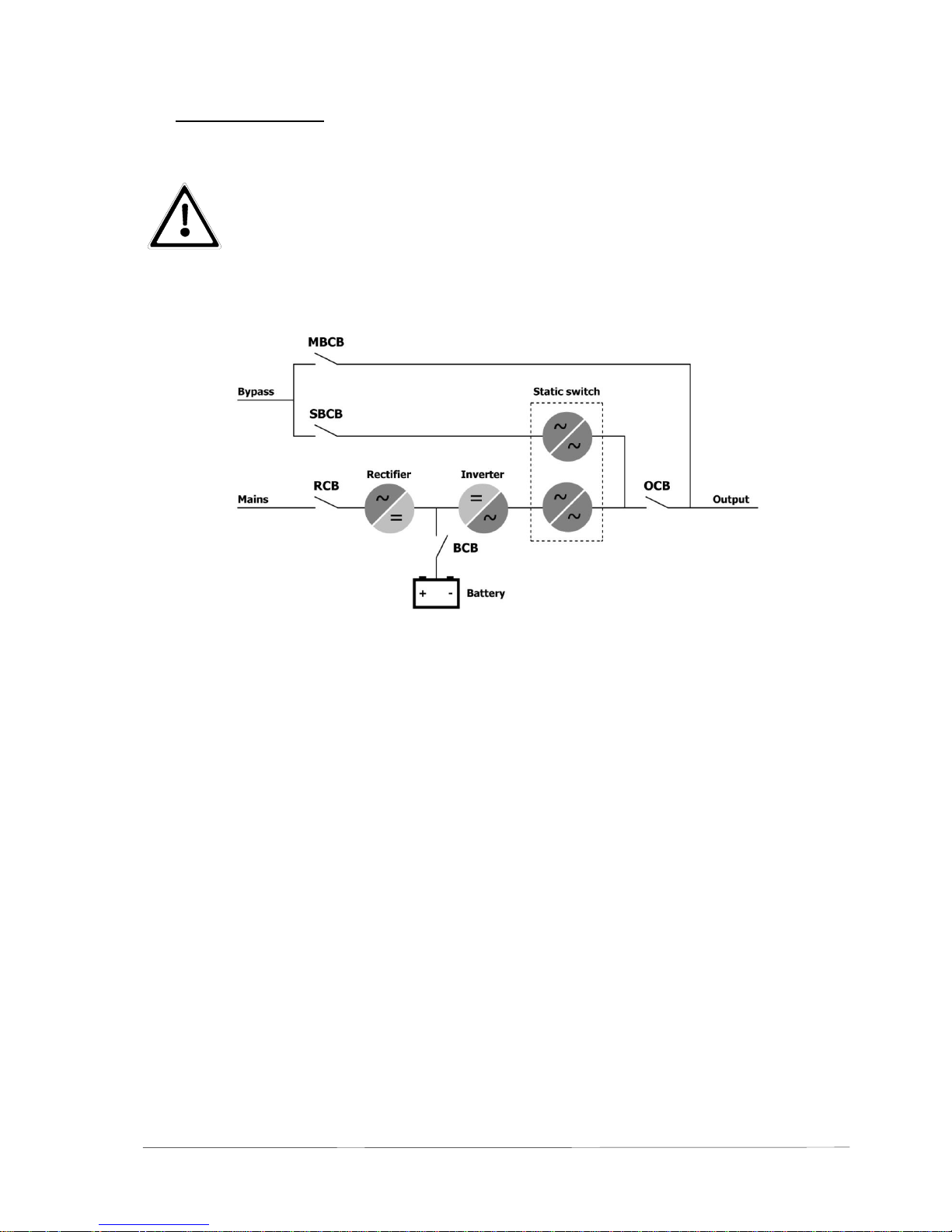
3 System description
UPS of this series are true on-line, double conversion UPS (classification-code VFI-SS-111); the inverter supplies the
load under normal operating conditions, whether mains is available or not (according to the battery autonomy time).
ATTENTION:
The UPS output is energized even during mains failure, therefore in compliance with the prescriptions of
EN 62040, the installer must label the outlets, plugs or lines supplied by the UPS, making the user aware
of this fact.
This true online concept guarantees great advantage to the user, as it supplies clean, continuously regulated power and
guarantees a stabilized voltage. Thanks to the double conversion principle, the load will be protected from microinterruptions due to excessive mains variation. It prevents damage to the critical load.
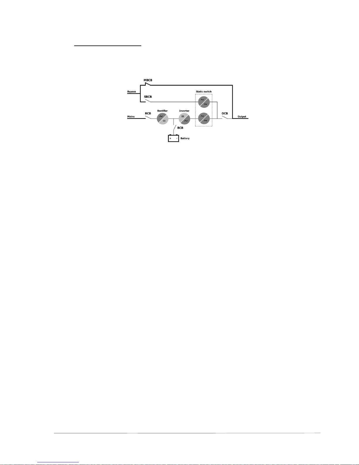
Block diagram
Legend of the block diagram:
Input UPS Input terminals (1L1, 1L2, 1L3, PE.)
Input Bypass Bypass input terminals (2L1, 2L2, 2L3, 2N, PE.)
RCB Rectifier Circuit Breaker
SBCB Static Bypass Circuit Breaker
MBCB Manual Bypass Circuit Breaker; only available at 200-300 kVA as standard
equipment, available at 400-800 kVA as option)
BCB Battery Circuit Breaker
OCB Output Circuit Breaker
UPS Output Output terminals (3L1, 3L2, 3L3, 3N, PE.)
Rectifier The IGBT rectifier converts the input AC-voltage into a regulated DC-voltage supply-
ing the inverter and charging the batteries.
Inverter The inverter converts the DC-voltage delivered by the rectifier or by the battery into
an AC-voltage, regulated by Pulse-Width-Modulation. The output of the inverter is
short circuit proof by electronic short-circuit-protection.
Static Switch The static bypass consists of a thyristor-switch. It switches the mains over to the UPS
output. During normal operation the inverter output is switched to the UPS output
while the bypass is blocked. During overload at the UPS output or an inverter failure
the attached loads will be supplied immediately by the bypass.
Manual Bypass The manual bypass feeds the load in case of maintenance or disturbances of the
UPS. The manual bypass is to be used only by qualified personnel under consideration of the described instructions in this manual!

Wärtsilä JOVYSTAR HP 200-800kVA BAX 4640 E - 12 -
ATTENTION:
A handling error of the internal or (if applicable) any external manual bypass could lead to a total
blackout at the output of the UPS!
3.1 Rectifier
It converts the three phase voltage of the AC mains into continuous DC voltage. It uses a three phase fully-controlled
IGBT bridge with a low harmonic absorption. The control electronics uses a 32 bit uP of latest generation that allows to
reduce the distortion of the current absorbed by mains (THDi) to less than 5%. This ensures that the rectifier does not
distort the supply mains, with regard to the other loads; it also avoids unlikely overheating of the cables due to the harmonics circulation.
The rectifier is so sized as to supply the inverter at full load and the battery at the maximum charging current.
3.2 Inverter
It converts the direct voltage coming from the rectifier or from the DC battery into alternating AC voltage stabilized in
amplitude and frequency. The inverter uses IGBT technology with a high changeover frequency of approximately 10
KHz. The control electronics uses a 32 Bit uP of latest generation that, thanks to its Processing capability, generates an
excellent output sine-wave.
Moreover, the fully digitized control of the output sine-wave allows to achieve high performances, among which a very
low voltage distortion even in presence of loads with high crest factor currents.
3.3 Battery and Battery Charger
The battery is installed outside the UPS. It is generally housed in an external battery cabinet. The battery charger logic is
completely integrated in the rectifier’s control electronics. The battery is charged, according to the DIN 41773 Standard,
every time it has been partially or completely discharged. When its full capacity is restored, it is kept floating so as to
compensate for any autodischarge.
3.4 Static Bypass
It serves to transfer the load between INVERTER and MAINS, and vice-versa, without interruption, and uses SCR’s as
power commutation elements.
3.5 Manual Bypass
It provides a solution of bypassing the UPS by itself, supplying the load directly by the mains in case of maintenance or
serious failure.
ATTENTION:
The sequence of switching to bypass must be carried out with respect to the procedure indicated on the
UPS and in the chapter “Operating the UPS”. The manufacturer cannot accept responsibility for damages
arising from incorrect operation.
3.6 Front Panel
The front panel of the UPS, consists of a double row alphanumeric display including 5 function keys, allows the complete
monitoring of the UPS status. A mimic diagram helps to understand the operating status of the UPS. For more information see the chapter “Operation”.
Wärtsilä JOVYSTAR HP 200-800kVA BAX 4640 E - 13 -
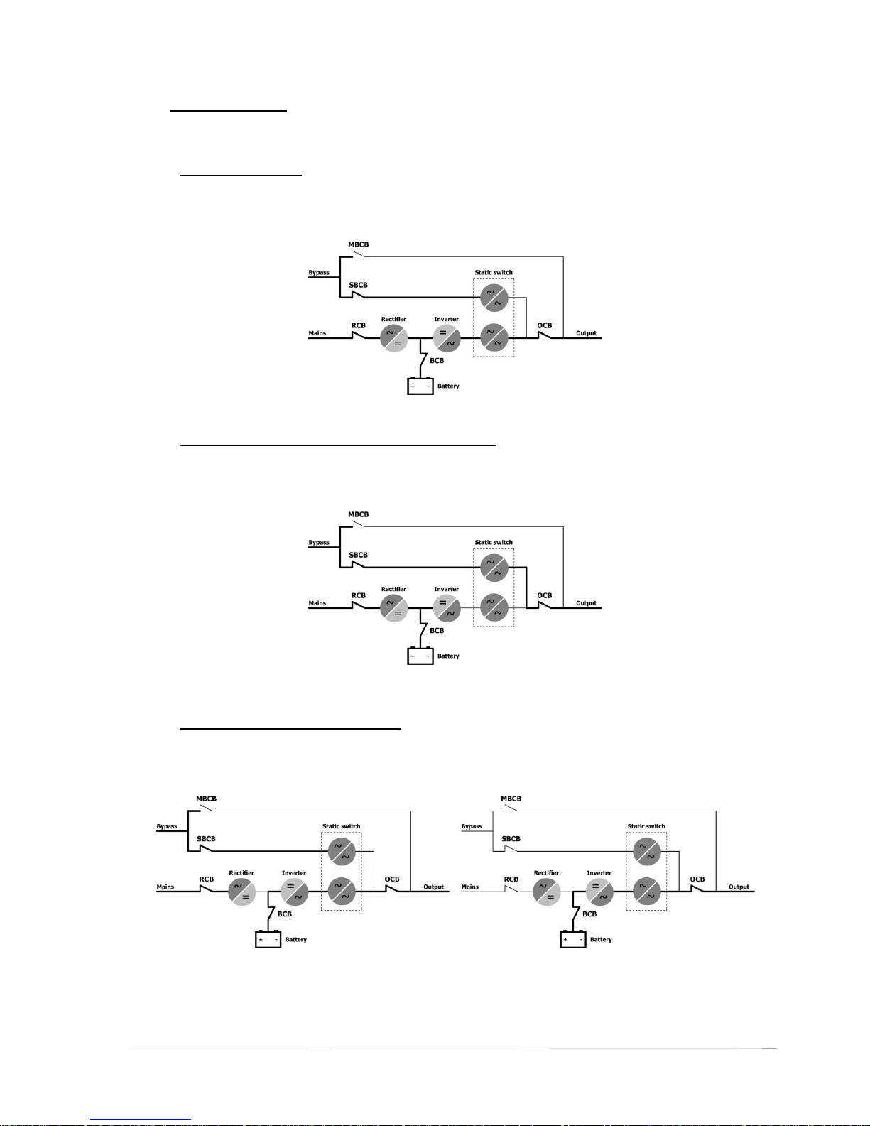
3.7 Operating status
The following paragraphs show all the possible operating status of the UPS.
3.7.1 Normal operation
The inverter is supplied by the rectifier, which also charges the battery. The load is supplied by the inverter output directly, via the inverter static switch SSI. The load is in the best conditions in terms of supply Protection.
3.7.2 Load supplied by bypass due to inverter fault
In case of inverter fault, the load is transferred to bypass, emergency line, through the static bypass switch SSB; the
transfer is carried out without interruption.
3.7.3 Rectifier failure or mains failure
The inverter is supplied by the battery for the stated autonomy time; the load, through the inverter static switch SSI, is
supplied directly by the inverter output.
Wärtsilä JOVYSTAR HP 200-800kVA BAX 4640 E - 14 -
3.7.4 Internal Manual bypass
The load is supplied by the input mains through the manual bypass. The operator can work in safety on the UPS to carry
out maintenance or repairing operations.

Wärtsilä JOVYSTAR HP 200-800kVA BAX 4640 E - 15 -
4 Installation
4.1 Reception of the UPS
After reception of the UPS, unpack immediately and carry-out an accurate visual check for any transport-damages.
IMPORTANT:
In case of objections relating to damage incurred during transport these must be immediately notified to
the transportation company after reception of the product.
When the UPS is not installed immediately it must be stored carefully in vertical position, as indicated on
the packing and conserved in a dry and sheltered room in its box so that it is protected from dust.
4.2 Transport
Before positioning the UPS, in order to avoid risks of turnover, it is recommended to move the system only while mounted on the wood pallet. Before the positioning in the final location, remove the pallet from the UPS. The UPS can be lifted
and handled using a pallet truck or a forklift.
ACHTUNG:
Paying attention to the center of gravity of the UPS! The brackets must be long sufficient and far enough
from each other stand.
i
Wärtsilä JOVYSTAR HP 200-800kVA BAX 4640 E - 16 -
4.3 Setting up
The UPS must be installed in a clean and dry room, preferably not dusty. The user must ensure a proper air conditioning
for cooling the equipment. If the UPS contains the batteries internally the air exchange with the external ambient must
comply with EN 62040, annex N.
Pay attention, that through the weight of the UPS and the batteries the maximum floor loading will not exeeded. You find
informations to the weights and the measurements in the technical data. In addition the site must fulfil the following requests:
- The UPS may be installed only in dry rooms.
- None caustic or acid steam may escape.
- The device supply air temperature may be maximally 40°C.
- Whem batteries are supplied to this UPS installation, the air exchange for these batteries with the external surroundings must according to EN 62040 appendix N.
- The vent holes at the device must not be covered by construction measures or other factors.
- The device is to be protected against direct solar radiation and action of other heat springs.
- The wall- and ceiling-distances as well as the recommended air flow volume (see also technical data) are complying for an optimum cooling of the UPS. An overheating of the system is thus avoided.
Wärtsilä JOVYSTAR HP 200-800kVA BAX 4640 E - 17 -
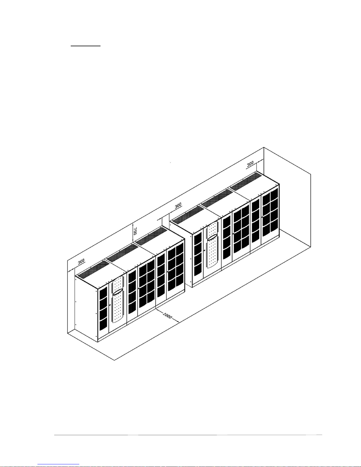
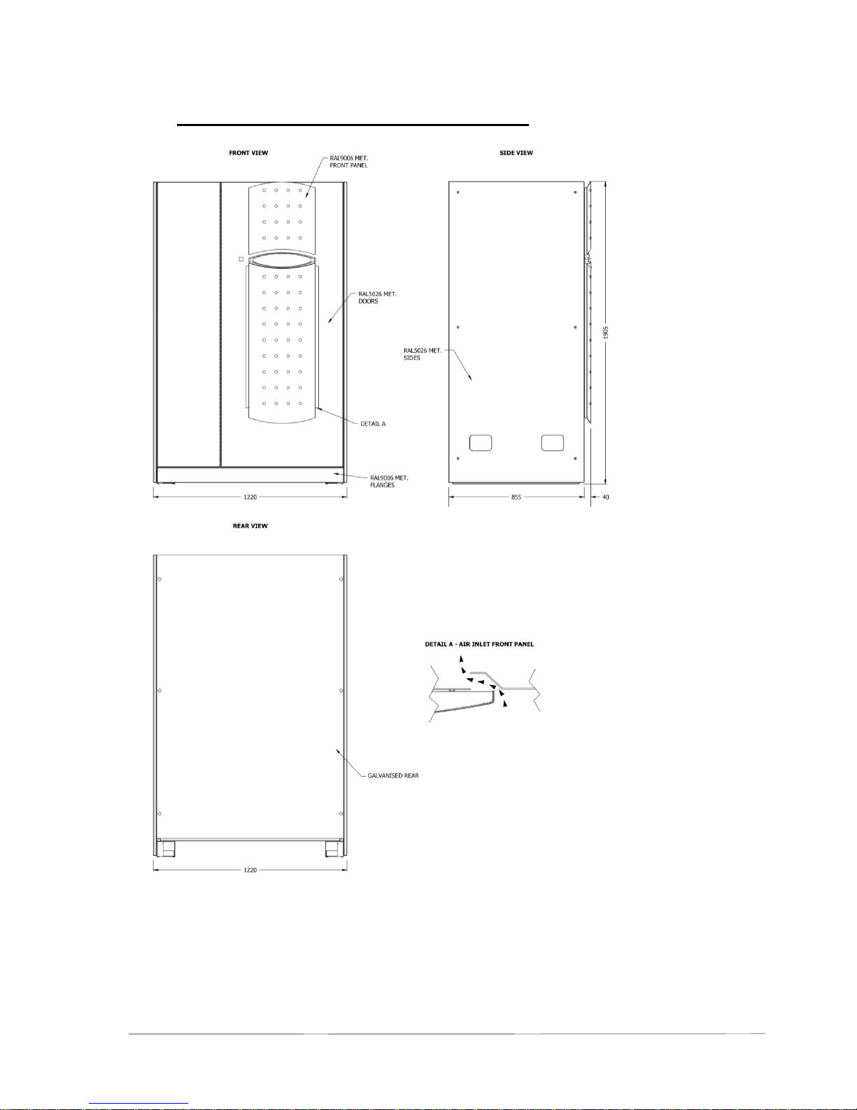
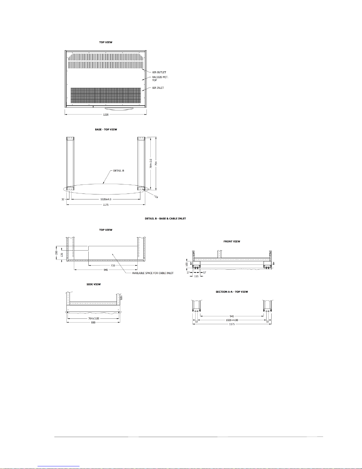
4.3.1 Dimensions Wärtsilä JOVYSTAR HP E 200-300 kVA
Wärtsilä JOVYSTAR HP 200-800kVA BAX 4640 E - 18 -

Wärtsilä JOVYSTAR HP 200-800kVA BAX 4640 E - 19 -
4.3.2 Dimensions Wärtsilä JOVYSTAR HP E 400 kVA

Wärtsilä JOVYSTAR HP 200-800kVA BAX 4640 E - 20 -

Wärtsilä JOVYSTAR HP 200-800kVA BAX 4640 E - 21 -
4.3.3 Dimensions Wärtsilä JOVYSTAR HP E 500-600 kVA

Wärtsilä JOVYSTAR HP 200-800kVA BAX 4640 E - 22 -

Wärtsilä JOVYSTAR HP 200-800kVA BAX 4640 E - 23 -
4.3.4 Dimensions Wärtsilä JOVYSTAR HP E 800 kVA

Wärtsilä JOVYSTAR HP 200-800kVA BAX 4640 E - 24 -

Wärtsilä JOVYSTAR HP 200-800kVA BAX 4640 E - 25 -

Wärtsilä JOVYSTAR HP 200-800kVA BAX 4640 E - 26 -
4.4 Electrical Connections
ATTENTION:
Even with switched off mains there is a dangerous high battery voltage inside the UPS. All installations
and connections may only be carried out by qualified technicians. The technician must familiarize himself
with the special features of this UPS by carefully reading and understanding this manual.
Please observe the special notices for connections of a parallel-system.
The work for electrical connection is a part of an electrician who installs the whole electric installation. It is not part of the
UPS manufacturer. For this reason, the following recommendations are only an indication, as the UPS manufacturer is
not responsible for the electrical installation.
In any case we recommend carrying out the installation and the electrical connections to the UPS in accordance to the
local rules and standards.
During the electrical installation make sure a right phase rotation at the three-phase input terminals of the UPS.
In case of strong electromagnetic fields emission it is recommended to use a shielded cable between UPS and the load.
In accordance to EN 62040-1 a mains-feed-back protection has to be provided for the UPS, preventing a current flow
from the output of the UPS back into mains at a single fault of the system. Therefore both the lines for the main input and
the bypass lines have to be fed via a contactor, which opens in case of a mains blackout.
For improving the quality of connection of the UPS flexible cables are recommended. A cable clamp must be provided by
the end-user directly at the structure of the frame or right below the UPS cabinet.
The wire diameters given in the below table refer to a distance of 20m between load and UPS. These values are recommendations only. They have to be recalculated particularly considering the actual environment conditions!
At larger distances the permissible voltage drop, the environmental temperature and the cable grounding have to be
dimensioned according to VDE or local rules. Local rules for the protection ground-wires have to be considered.
The suitable diameters of cables and the sizes of the fuses are to be designed with regard to the environmental temperature, the cable grouping and length of cables according to the local rules and according to VDE.
The terminals are positioned at the lower part of the UPS and they can be accessed by opening the front door.
ATTENTION:
The input lines to the UPS must be fuse protected. The use of residual current switches in the line supplying the UPS is not recommended. The leakage current due to the RFI filters is rather high and it can
cause spurious tripping of the protection device.
If any residual-current-switch has to be used, it is recommended the use of a device with short-time delay for differential currents higher than 300mA.
The following table represents a summary about the current carrying capacity acc. DIN VDE- and EN-rules at an environmental temperature of 30°C. The necessary diameters of cable and the sizes of the fuses are to be designed with
regard to the environmental temperature, the cable grouping and length of cables according to the local rules and according to VDE.
NOTE:
The suitable cable cross-sections and sizes of the fuses must be determined considering the ambient
temperature, the cable grouping and the cable lengths according to the local rules and the local regulations of the electrician or planner. Since the manufacturer of the installation does not know the local
factors, a liability of the manufacturer is impossible concerning the electrical installation.
The given values of cable diameters do not reflect the required diameters of the protective earth cable! They
have to be calculated in accordance to VDE 0100 part 540 or an applicable local rule.
UPS size
200kVA
250kVA
300kVA
Input fuses [AgL]
Rectifier
3 x 315
3 x 400
3 x 500
Bypass
3 x 315
3 x 400
3 x 500
Input cables (mm²)
Rectifier
3 x 185
3 x 240
3 x 2 x 150
Bypass
4 x 185
4 x 240
4 x 2 x 150
Output cables (mm²)
4 x 185
4 x 240
4 x 240
Battery cables (mm²)
2 x 240
2 x 240
2 x 2 x 185
External battery cabinet, circuit breaker / fuses [AgL]*
2 x 400
2 x 400
2 x 500
* applicable for DC-applications
i

Wärtsilä JOVYSTAR HP 200-800kVA BAX 4640 E - 27 -
UPS size
400kVA
500kVA
600kVA
800kVA
Input fuses
Rectifier
3x 630AgL
3x 800AgL
3x 1000AgL
3x 1250AgL
Bypass
3x 800AgL
3x 1000AgL
3x 1250AgL
3x 1600AgL
Input cables
Rectifier (1L1-1L2-1L3)
2x3x150mm²
3x3x150mm²
4x3x150mm²
3x3x240mm²
Bypass (2L1-2L2-2L3-2N)
2x4x185mm²
3x4x185mm²
4x4x185mm²
3x4x240mm²
Output cables (3L1-3L2-3L3-3N)
2x4x185mm²
3x4x185mm²
4x4x185mm²
3x4x240mm²
Set value for circuit-breakers( for 3 battery strings)
3x250A
3x315A
3x355A
-
Battery cables (±B1…±B3) ( for 3 battery strings)
3x2x95mm²
3x2x120mm²
3x2x150mm²
-
Set value for circuit-breakers( for 4 battery strings)
4x200A
4x250A
4x315A
4x355A
Battery cables (±B1…±B4) ( for 4 battery strings)
4x2x70mm²
4x2x95mm²
4x2x120mm²
4x2x150mm²
Set value for circuit-breakers( for 5 battery strings)
- - -
5x315A
Battery cables (±B1…±B5) ( for 5 battery strings)
- - -
5x2x20mm²
ATTENTION:
For ensuring the selectivity all fuses should have the utilization category “gL”. When using higher fuse
ratings or circuit breakers a selectivity calculation must be carried out according to the local requirements. For battery fuses a suitable breaking capability must be ensured.
4.4.1 Terminal Board
WARNING:
The UPS requires the neutral of the bypass input only (2N). When using the neutral of the main input too,
both neutrals have to be connected together.
Terminal board 200-300 kVA:
300 (200 kVA) / 195 (250
-300 kVA)
214
3-L1 3-L2 3-L3 3-N 2-L1 2-L2 2-L3 2-N +B -B
(R) (S) (T) (N) (R) (S) (T) (N)
1-L1 1-L2 1-L3
(R) (S) (T)

Wärtsilä JOVYSTAR HP 200-800kVA BAX 4640 E - 28 -
Terminal board 400 kVA:

Wärtsilä JOVYSTAR HP 200-800kVA BAX 4640 E - 29 -
Terminal board 500-800 kVA:

Wärtsilä JOVYSTAR HP 200-800kVA BAX 4640 E - 30 -
4.4.2 Internal Connections between both switch cabinets:

Wärtsilä JOVYSTAR HP 200-800kVA BAX 4640 E - 31 -
4.4.3 Battery connection
IMPORTANT:
Prior to connecting to any external battery the standard EN62040, par. 4.5 must be observed. For ensuring the maximum lifetime for the battery, according to the statements of the battery manufacturer, the
operating temperature of the battery must be held between 20°C and 25°C. Otherwise the lifetime will be
reduced drastically, even in the case that the battery can work at temperatures of up to 40°C. For preventing of forming explosive gases of hydrogen/oxygen mixtures a suitable air-ventilation has to be installed according to EN62040, Annex N).
It is recommended install the battery, only if the UPS will be able to recharge it. Consider that a battery which is not being
charged within 2-3 months can be irreversibly damaged.
IMPORTANT:
A battery must be maintained periodically. Observe the instruction manual of the battery manufacturer. It
will be found in the annex of this manual.
WARNING:
After switching off the UPS, please open the battery circuit breakers and, if present, the fuses for the
battery symmetry monitoring resp. the charging circuit monitoring fuses. In other case, the power supply
consume a little current from the Battery. After a couple of hours, the battery will be deep discharged.
IMPORTANT:
If the batteries are not supplied in complete battery cabinets, extra fuses or circuit breakers are to be
planned for the battery. Alternatively a BAU (Battery adapter unit) is available as an option.
Type of battery cabinet
B14
Dimensions Width [mm]
Height [mm]
Depth [mm]
1072
1900
910
Weight of cabinet without batteries [kg]
260
Protection degree
IP 20 according to DIN 40050
Protection class
1 according to VDE 0106 / part 1
For information about the connection of a row of battery cabinets please refer to the wiring diagram in annex.
Battery connection 200-300 kVA:
Battery connection 400-800 kVA:
See wiring diagram U88 034 00.VP3 in appendix!
i
i
i
USV
Ext. Batterie-
schrank „1“
Ext. Batterie-
schrank „n“
UPS
Ext. Battery
cabinet „1“
Ext. Battery
cabinet „n“

Wärtsilä JOVYSTAR HP 200-800kVA BAX 4640 E - 32 -
5 Operation
Prior to carrying out whatever procedure described in this chapter, read carefully the instructions, in order to avoid possible damages to persons or the UPS due to wrong manoeuvre.
5.1 Setting Up
NOTE:
The battery circuit breakers BCB may be switched only when the rectifier is running. Otherwise the rectifier
could be damaged. The BCBs are installed inside the battery cabinets.
Procedure:
Close RCB and wait until display is coming up. Follow the instructions shown on the display to close the circuit breakers
and/or isolator switches as indicated. Do not close any switches before they were not called for that through the display.
If the start-up procedure has been carried out correctly, the display will show:
No.
LCD DISPLAY
ACTION
UPS OPERATION
1
BLANK
Close RCB
2 BOOT LOADING
3
EEPROM READING
4
UPS START UP
WAIT PLEASE
The rectifier is supplied and the DC voltage increases up to the nominal value. All
LED’s in the front panel are lit green. The microprocessor checks all the start-up
conditions are ok. LED’s #1 and #3 are lit green.
5
RECTIFIER START UP
WAIT PLEASE
The IGBT rectifier bridge starts to modulate and the inverter input voltage reaches
the nominal value. LED #3 green light on.
6
INVERTER START
WAIT PLEASE
The inverter bridge starts to modulate and the AC voltage reaches the nominal
value. After a few seconds the static inverter switch closes. LED #5 green light on.
7
BYPASS START UP
CLOSE SBCB
Close SBCB
8
BYPASS START UP
WAIT PLEASE
The microprocessor checks that all the bypass parameters (voltage, phase sequence, frequency) are within the tolerance limits. LED #2 green light on.
9
BATTERY START UP
CLOSE BCB
Close BCB *)
10
BATTERY START UP
WAIT PLEASE
The microprocessor checks that all the conditions for the following steps are ok.
LED #4 green light on.
11
UPS START UP
CLOSE OCB
Close OCB
12
START UP END
WAIT PLEASE
The microprocessor checks that all the output parameters (voltage, current, frequency) are within the tolerance limits. LED #7 green light on.
13
UPS MODEL
OUTPUT POWER
After a short time the default screen is displayed.
*) In this way the battery circuit-breakers are to be closed in the external battery cabinets. If in the installation a battery charging circuit symmetry supervision is built-in, the reset key S1 is to be pressed additional on everyone of the built-in monitorings (see options chapters).
5.1.1 Start-up troubleshooting
This paragraph provides the basic information if any alarms occur during the start-up procedure. In case the problem
cannot be solved contact the service department.
1. After having closed the RCB the LCD display is still blank
a. Check the input phase rotation.
b. Check the rectifier protection fuses; these are installed inside the UPS.
2. After Step #2 the UPS does not go on to Step #3 and displays the alarm A1 – Network failure
a. Make sure alarm A2 is functioning. Check the input phase rotation.
b. Check the rectifier protection fuses F1-F2-F3.
3. After Step #3 the UPS displays alarm messages
a. Open RCB and check the connections.
b. Close RCB and try to restart the UPS.
4. After Step #4 the UPS displays alarm messages
a. Check that the EPO button, if provided on the outside of the UPS, is in the release position
b. Open RCB and control the connections.
c. Close RCB and try restarting the UPS.
5. After Step #5 the display does not go to Step #6 and displays the alarm A15 – BYP NOT AVLB
a. Check the protection fuses of the Bypass static switch; they are installed inside the UPS.
i

Wärtsilä JOVYSTAR HP 200-800kVA BAX 4640 E - 33 -
b. Control the phase rotation voltage.
c. Check that the voltage and frequency are within the tolerance limits.
6. After Step #7 the display does not go on to Step #8 and the alarm A7 – BCB OPEN is displayed.
a. Check the battery fuses.
b. Control the inter-connection between the auxiliary contact of the battery switch (in the external cabinet)
and the clamps Bac1-Bac2 of the UPS.
WARNING:
Please contact our Service department after a failure. WÄRTSILÄ JOVYATLAS EUROATLAS does not
take over any liability for late error reports.
5.2 Shut down procedure
Nr.
ACTION
LCD DISPLAY
UPS OPERATION
1
Open OCB
A30 GENERAL ALARM
The supply to the load is interrupted. LED #7 lit orange
2
Open BCB
A30 GENERAL ALARM
The battery is disconnected from the rectifier. LED #4 flashing red light.
3
Open SBCB
A30 GENERAL ALARM
The bypass line is disconnected. LED #2 off.
4
Open RCB
A30 GENERAL ALARM
Booster and Inverter are switched off.
5
BLANK
End of shut down procedure.
CAUTION:
Even at switched off input mains, a dangerous high voltage is still present inside the UPS!
5.3 Starting the Parallel Redundant System
At commissioning of UPS units in parallel-redundant operation the SLAVE-UPS(s) have to be started first exactly in the
same manner it is described for a single unit. The last UPS to be started is the master-UPS.
5.4 Switch Off the Parallel Redundant System
All instructions also apply for parallel-redundant operation.
5.5 Manual bypass procedure
ATTENTION:
Switching the MBCB in a wrong sequence could lead to a blackout for the loads. The use of the manual
bypass is only designated for qualified personnel. Please consult our service department or your dealer
before using the manual bypass!
We strongly point out that the load is not supplied with a secure power-supply when using either the
internal or an external bypass. A mains blackout could lead to an interruption of the power-supply to the
load.
The UPS has to operate synchronously to the mains if you want to activate the manual bypass. This is guaranteed if the
status S5 is active!
Nr.
ACTION
LCD DISPLAY
UPS OPERATION
1
Move the bypass
selector SW to BYPASS
A30 GENERAL ALARM
The load is transferred to the bypass line. LED #5 off, LED #6 lit
orange.
2
Close MBCB
A30 GENERAL ALARM
The inverter is switched off. The load is supplied by the input mains
through the manual bypass switch. The static bypass switch is still
closed. Led #8 lit orange.
3
Open BCB
A30 GENERAL ALARM
The battery is disconnected from the DC bus bar. Led #4 red flashing.
4
Open RCB
A30 GENERAL ALARM
The supply input is opened; the rectifier shuts down. LED #1 off.
5
Open OCB
A30 GENERAL ALARM
The load remains fed by the manual bypass switch. LED #8 off.
6
Open SBCB
A30 GENERAL ALARM
The bypass line is disconnected. The display goes out.

Wärtsilä JOVYSTAR HP 200-800kVA BAX 4640 E - 34 -
7
BLANK
The load is supplied directly by the mains through the manual bypass
switch. The UPS is isolated.
CAUTION:
Even at switched off input mains, a dangerous high voltage is still present inside the UPS!
NOTE:
The load is powered now by the mains. Any blackout in the mains will lead to a blackout for the loads.
5.5.1 Start-up from manual bypass (Single UPS)
Before the start-up from manual by-pass (after maintenance or repairing) check that the “NORMAL-BYPASS” switch is in
BYPASS position.
Nr.
LCD DISPLAY
ACTION
UPS OPERATION
1
BLANK
Close RCB
2
BOOT LOADING
“BOOT” phase where the UPS firmware can be updated following the
appropriate procedure. All the LED’s on the front panel are on.
3
EEPROM READING
Reading of the configuration parameters stored in the EEPROM.
All the LED’s on the front panel are off.
2
UPS START UP
WAIT PLEASE
The rectifier is supplied and the DC voltage reaches the nominal value.
All the LED’s on the front panel are on.
The microprocessor checks that all the start-up conditions are good for
restart.
Led #1 lit green. Led #8 lit orange.
5
RECTIFIER START UP
WAIT PLEASE
The IGBT rectifier bridge starts to modulate; VDC voltage reaches the
nominal value. LED #3 is lit green: DC voltage present.
6
START UP FROM MBCB
CLOSE BCB
Close SBCB
7
BYPASS START UP
WAIT PLEASE
The microprocessor checks that all the bypass parameters (voltage,
phase rotation, frequency) are within tolerance. Led #2 lit green. The
static bypass switch is closed. LED #6 lit orange.
8
START UP FROM MBCB
CLOSE BCB
Close BCB
Closing of the battery circuit breaker.
Led #4 lit green.
9
START UP FROM MBCB
CLOSE OCB
Close OCB
The load is fed by the static bypass switch. Circuit breaker MBCB is still
closed. Led #7 lit green.
10
START UP FROM MBCB
OPEN MBCB
Open MBCB
The load is fed by the static bypass switch and the inverter can be started. LED #8 off.
11
INVERTER START
WAIT PLEASE
The modulation of the inverter bridge is started. The AC voltage reaches
the nominal value. The microprocessor checks the synchronization with
the bypass line.
12
START UP FROM MBCB
MOVE BYP - SWITCH
Move the selector
“NORMAL-BYPASS” to
NORMAL
The load is transferred to the inverter. Led #5 lit green.
13
START UP END
WAIT PLEASE
The microprocessor checks that all the output parameters (voltage,
current, frequency) are within the tolerance limits.
14
UPS MODEL
OUTPUT Power
i

Wärtsilä JOVYSTAR HP 200-800kVA BAX 4640 E - 35 -
5.5.2 Initiation of the Manual Bypass in Parallel Redundant Operation
The procedure must be carried out at every UPS unit:
- Set the service switch into Bypass position, wait and acknowledge the alarm as described for a single UPS
- Close MBCB, wait and acknowledge the alarms as described for a single UPS operation
- Open OCB.
- Open BCB.
- Open SBCB.
- Open RCB
5.5.3 Switch Off the Manual Bypass in Parallel Redundant Operation
Conditions:
- The UPS system is already switched off, the manual bypass MBCB is active.
- The service switch is set in bypass position.
- During start-up check the messages on the display!
Procedure:
… in SLAVE-UPS: - Close the RCB.
after request on the display - Close the SBCB.
after request on the display - Close the BCB.
after request on the display - Close the OCB.
… in both UPS
after request on the display - Open MBCB.
after request on the display - Service switch on “Normal” position.
…(in MASTER-UPS) - Close the RCB.
after request on the display - Close the SBCB.
after request on the display - Close the BCB.
after request on the display - Close the OCB.
5.6 Front Panel
The front panel of the UPS, consisting of a double row alphanumeric display plus 5 function keys, allows the complete
monitoring of the UPS status. The mimic flow helps to understand the operating status of the UPS.
5.6.1 Mimic description
The above picture shows the mimic present on the display, with the names of the circuit breakers/isolator switches of the
UPS. Also the led's and blocks that comprise the UPS are clearly identified.
LED-No.
LED-Display
Description
LED 1
green bright
Mains on rectifier input available and within the tolerance
green flashing
Wrong phase rotation of the input mains
off
Mains fault on rectifier input
LED 2
green bright
Bypass mains available and within the tolerance
green flashing
Wrong phase rotation of the bypass mains
off
Bypass mains fault or bypass mains out of the tolerance
LED 3
green bright
Rectifier on and rectifier output voltage within the tolerance
green flashing
Rectifier off or rectifier fault
red bright
Rectifier outputs voltage out of the tolerance
LED 4
green bright
BCB (Battery-breaker) closed and battery will charged
green flashing
Battery discharging or battery test

Wärtsilä JOVYSTAR HP 200-800kVA BAX 4640 E - 36 -
orange flashing
BCB (Battery-breaker) opened
red bright
Battery test failed
off
Batterie nicht verfügbar
LED 5
green bright
Inverter outputs voltage within the Tolerance and static switch closed
green flashing
Inverter overload or short circuit
off
Inverter off or inverter outputs voltage out of the tolerance
LED 6
orange bright
Static switch bypass closed
orange flashing
switching over blocked
off
Static switch bypass opened
LED 7
green bright
OCB (Outputs switch) closed
off
OCB (Outputs switch) opened
LED 8
orange bright
MBCB (Manuel bypass switch) closed
off
MBCB (Manuel bypass switch) opened
LED 9
red bright
EPO (Emergency switch) activated
off
Normal mode
LED 10
orange langsam
flashing
Requirement maintenance
orange schnell
flashing
Critical alarm - service contact
off
Normal mode

Wärtsilä JOVYSTAR HP 200-800kVA BAX 4640 E - 37 -
5.7 Menu structure
5.7.1 Measures
The measured data of the UPS are saved in the main menu under “Measures”. It can be displayed the input,
output and bypass values, as well as data about the assemblies rectifier, inverter and battery.
„UPS-NAME“
MEASURES
„UPS-NAME“
ALARMS
Password-entry is required!
„UPS-NAME“
SPECIAL
„UPS-NAME“
INFO
Sub menu
Display
Voltage is based on N-connector
MEASURES
INPUT
INPUT VOLTAGE
xxx yyy zzz V
INPUT FREQUENCY
xx.x Hz
INPUT POWER
xxx kVA
INPUT
EXIT
Main menu
„UPS-NAME“
xxx kVA
INPUT CURRENT
xxx yyy zzz A
RESET
RESET
Voltage is based on N-connector
MEASURES
OUTPUT
OUTPUT VOLTAGE
xxx yyy zzz V
OUTPUT FREQUENCY
xx.x Hz
OUTPUT POWER
xxx kW
OUTPUT POWER
yyy kVA
OUTPUT CURRENT
xxx yyy zzz A
LOAD
xxx yyy zzz %
RESET

Wärtsilä JOVYSTAR HP 200-800kVA BAX 4640 E - 38 -
Sub menu
Display
Voltage is based on N-connector
MEASURES
BYPASS
BYPASS VOLTAGE
xxx yyy zzz V
BYPASS
EXIT
Main menu
BYPASS FREQUENCY
xx.x Hz
RESET
Voltage is based on N-connector
MEASURES
INVERTER
INVERTER VOLTAGE
xxx yyy zzz V
INVERTER
EXIT
INVERTER FREQUENCY
xx.x Hz
RESET
MEASURES
AC / DC
AC / DC VOLTAGE
xxx V
AC / DC
EXIT
RESET
MEASURES
BATTERY
BATTERY VOLT/CURR
xxx V xxx A
BATTERY AUTONOMY
xxx Min yyy %
BATTERY TYPE
xx.x Ah
RESET
BATTERY
EXIT
MEASURES
EXIT
OUTPUT
EXIT

Wärtsilä JOVYSTAR HP 200-800kVA BAX 4640 E - 39 -
5.7.2 Alarms
The menu “Alarms” displays the status of the UPS and the alarms. All active alarms and status reports will be displayed
in the sub menu “UPS Status”. If a fault occurs, the status menu automatically appears and presents the relevant report
on the display. In addition, an acoustic signal will sound, which can be disabled by pressing the buzzer button. Occurred
and removed faults are saved and can be displayed in the sub menu “History” at any time.
(See also list of status reports)
(See also list of alarms)
Star (*) next to fault code means:
Fault was removed at the specified time
„UPS-NAME“
MEASURES
„UPS-NAME“
ALARMS
Password-entry is required!
„UPS-NAME“
SPECIAL
„UPS-NAME“
INFO
Sub menu
Display
ALARMS
UPS STATUS
USV STATUS
(First status report)
Main menu
„UPS-NAME“
xxx kVA
USV STATUS
(Last status report)
RESET
RESET
Fault was detected at the specified time
ALARMS
HISTORY
HISTORY
HISTORY: xxx/yyyy
Code Date/Time
HISTORY
HISTORY: xxx/yyyy
Code* DATE/TIME
RESET
ALARMS
EXIT

Wärtsilä JOVYSTAR HP 200-800kVA BAX 4640 E - 40 -
5.7.3 Special
Different settings to the UPS can be made in the “Special”-menu. For that a password entry is necessary, to
prevent a change of the system data by unauthorized persons. Then the following settings can be made:
Reset of the UPS, set Date/Time, select language, perform an UPS test, enter battery data, perform a battery test, install new battery, delete history, set modbus address and reset running time.
UPS automatically switches from Inverter
mode to bypass mode and returns
Caution: In bypass fault, an immediate-
ly inverter operating during the test
phase cannot be guaranteed! A failure
of the load is possible!
Change language of the display output
Set date and time
„UPS-NAME“
MEASURES
„UPS-NAME“
ALARMS
Password-entry is required!
„UPS-NAME“
SPECIAL
„UPS-NAME“
INFO
Sub menu
Display
Main menu
„UPS-NAME“
xxx kVA
RESET
SPECIAL
CLOCK SETTINGS
CURSOR-Keys: Selection of a digit (0-9)
RETURN: Confirmation of a digit
RESET: Cancel current selection of digit
and back to previous digit
CLOCK SETTINGS
DD-MM-YY hh:mm
SPECIAL
SELECT LANGUAGE
CURSOR-Keys: Selection of the language
RETURN: Confirmation of the language
More languages
2 – DEUTSCH, 3 – FRANCAIS,
4 – ENGLISH, 5 – PORTUGUES,
6 – ESPANOL, 7 – POLSKI,
8 – TURKCE
SELECT LANGUAGE
1 – ITALIANO
Note: Lower interventions are made in
the system
(Input wrong password: Exit)
CURSOR-Keys: change digit
RETURN: Confirmation of a digit
ENTER PASSWORD
123
Reset of the UPS: Active fault conditions
are reset
SPECIAL
RESET
CURSOR-Keys: Selection YES/NO
RETURN: Confirmation YES/NO
RESET DEVICE?
YES / NO
RESET
RESET
RESET
SPECIAL
UPS TEST
CURSOR-Keys: Selection YES/NO
RETURN: Confirmation YES/NO
UPS TEST
YES / NO
RESET

Wärtsilä JOVYSTAR HP 200-800kVA BAX 4640 E - 41 -
Caution: The test can affect the supply
of the load if the battery is not fully
charged
Short discharge test of the battery;
“Battery fault” appears, if battery not O.K.
Set the battery properties:
Capacity, charging current, autonomy time
Sub menu
Display
Main menu
CURSOR-Keys: Selection YES/NO
RETURN: Confirmation YES/NO
CONFIRM AUTON BATT?
YES / NO
CURSOR-Keys: Selection YES/NO
RETURN: Confirmation YES/NO
SAVE BATT SETTINGS?
YES / NO
BATT SETTINGS SAVED
SPECIAL
BATTERY SETTING
CURSOR-Keys: Selection of a digit (0-9)
RETURN: Confirmation of a digit
RESET: Cancel current selection of digit
and back to previous digit
BAT CAPACITY SETTING
xxx.x Ah
CURSOR-Keys: Selection YES/NO
RETURN: Confirmation YES/NO
CONFIRM BATT CAP.?
YES / NO
CURSOR-Keys: Selection of a digit (0-9)
RETURN: Confirmation of a digit
RESET: Cancel current selection of digit
and back to previous digit
BAT RECHAR CURR SET
xx.x A
CURSOR-Keys: Selection YES/NO
RETURN: Confirmation YES/NO
CONFIRM RECHAR CURR?
YES / NO
CURSOR-Keys: Selection of a digit (0-9)
RETURN: Confirmation of a digit
RESET: Cancel current selection of digit
and back to previous digit
AUTONOMY BAT SETTING
xxxx min
RESET
(4x)
(2x)
(4x)
SPECIAL
BATTERY TEST
CURSOR-Keys: Selection YES/NO
RETURN: Confirmation YES/NO
BATTERY TEST?
YES / NO
RESET

Wärtsilä JOVYSTAR HP 200-800kVA BAX 4640 E - 42 -
Reset running time to zero
Set modbus address
Delete history
Sub menu
Display
Main menu
SPECIAL
RESET RUNNING HOURS
SPECIAL
EXIT
CURSOR-Keys: Selection YES/NO
RETURN: Confirmation YES/NO
RESET HISTORY?
YES / NO
SPECIAL
RESET HISTORY
SPECIAL
MODBUS
CURSOR-Keys: Selection of a digit (0-9)
RETURN: Confirmation of a digit
RESET: Cancel current selection of digit
and back to previous digit
(Address range: 1… 247)
MODBUS ADDRESS
xxx
CURSOR-Keys: Selection YES/NO
RETURN: Confirmation YES/NO
RESET RUNNING HOURS?
YES / NO
RESET
RESET
RESET
Set autonomy time of the new installed
battery to 100 %
CURSOR-Keys: Selection YES/NO
RETURN: Confirmation YES/NO
SPECIAL
NEW BATTERY INSTALL
NEW BATTERY INSTAL?
YES / NO
RESET

Wärtsilä JOVYSTAR HP 200-800kVA BAX 4640 E - 43 -
5.7.4 Info
The menu “Info” include all relevant information of the UPS as the serial numbers (Device and job number),
the device type (Online-/Eco mode and single or parallel system), the device data at a parallel system (Only
active, if available), the modbus address, the versions of the installed firmware, the service remark (Only
active, if available) and the running time.
„UPS-NAME“
MEASURES
„UPS-NAME“
ALARMS
Password-entry is required!
„UPS-NAME“
SPECIAL
„UPS-NAME“
INFO
Sub menu
Display
Main menu
„UPS-NAME“
xxx kVA
RESET
INFO
DEVICE TYPE
Display the device serial number
UPS SERIAL NUMBER
xxxxxxxxxx
Display the job number
OEM SERIAL-NUMBER
xxxxxxxxxx
SERIAL-NUMBER
EXIT
INFO
SERIAL NUMBER
Possibility: On Line/Eco mode
DEVICE TYPE
UPS – ON LINE
Possibility: Single/Parallel
DEVICE TYPE
SINGLE
RESET
RESET
DEVICE TYPE
EXIT

Wärtsilä JOVYSTAR HP 200-800kVA BAX 4640 E - 44 -
CAN bus statistic static switch:
Number of received data and number of
correctly received data in percent
All UPS devices send data;
All UPS devices receive data
Sub menu
Display
Main menu
Parallel menu only visible, if the UPS
belongs to a parallel system!
POWER: All UPS devices supply the load
REDUNDANT+X: X = Number of the UPS
devices in the parallel-standby mode
Digit = Device number in the parallel
system; M = Master, S = Slave;
? = No communication exists on the data
bus in the parallel system;
[ ] = Identify position/configuration of the
current UPS in the parallel system
Position of the current UPS in the parallel
system/Number of UPS devices in the
parallel system
PARALLEL
x / y
Possibility: Master/Slave
Only a master possible, or faults in the data
communication bus
PARALLEL
MASTER
PARALLEL
EXIT
INFO
PARALLEL
PARALLEL
1- S 2- M 3-[S] 4- ?
PARALLEL
REDUNDANT+X
PARALLEL
CAN STATISTICS SSW
MSG RX: xxxxx xxx.x%
RESET
CAN bus inverter:
Number of received data and number of
correctly received data in percent
Only the master sends data;
Only the slaves receive data
PARALLEL
CAN STATISTICS INV
SYNC RX: xxxxx xxx.x%
CAN bus inverter:
Number of received data and number of
correctly received data in percent
All UPS devices send data;
All UPS devices receive data
PARALLEL
CAN STATISTIK INV
MSG RX: xxxxx xxx.x%
Display the modbus address
INFO
MODBUS
Settable address range: 1… 247
MODBUS
ADDRESS: xxx
RESET

Wärtsilä JOVYSTAR HP 200-800kVA BAX 4640 E - 45 -
Siehe Kontaktdaten/Service informieren
Service menu only visible, if a service
remark is active
Sub menu
Display
Main menu
See contact data/Notify the service
INFO
SERVICE
FIRMWARE RELEASE
EXIT
SERVICE
---------- Sliding text ----------
SERVICE
EXIT
INFO
RUNNING HOURS
RUNNING HOURS
xxxxxx
RUNNING HOURS
EXIT
Microcontroller of the static switch
FIRMWARE RELEASE
uC S: vv.xx.yy.zz
RESET
RESET
INFO
EXIT
Digital signal processor of the inverter
Digital signal processor of the rectifier
INFO
FIRMWARE RELEASE
FIRMWARE RELEASE
DSP1 R: vv.xx.yy.zz
FIRMWARE RELEASE
DSP2 I: vv.xx.yy.zz
RESET
MODBUS
EXIT

Wärtsilä JOVYSTAR HP 200-800kVA BAX 4640 E - 46 -
6 Options
6.1 Parallel redundant system
The parallel system can consist of up to 5+1 (redundant parallel) or 6 (power parallel) units. Each unit is equipped with
an additional parallel-redundant kit for controlling the parallel related functions.
In addition to the standard functions such as uninterruptible power supply to the load, total power control and protection
of the load from mains distortion, the parallel redundant system guarantees an uninterrupted power supply even in case
of an internal failure in one of the UPS units.
The current sharing regulation circuitry controls the currents of the “n” units and therefore balances the currents to better
than 10%, under all load conditions. The load supplied by the inverters in parallel may have an instantaneous overload
up to “n x 200%” of the nominal load of the single unit. In case of a failure in one unit, the load is still supplied by the
other units. The load transferred to the static bypass only in case of failure of more than one unit.
NOTE:
For obtaining a balanced load-sharing between the single UPS-systems, it is mandatory to keep the input(i.e. Bypass-) lines as well as the output lines of the single units with the same length to each other and to
the distribution. In cases of extremely short length of wires, and also in cases of a very high diameter of the
cables, it is possible, that the load sharing between the single units is weak. In these cases an adjustment
at the final operating place of the units will be necessary.
6.1.1 Additional hardware
To transform “n” standard units into a parallel redundant system the following additional hardware is required:
“n” PCB SLOT-PAR (PB214)
“n” CANBUS-Cable (SUB-D9, 1:1)
The outputs of the “n” units must be connected in parallel to the load bus bar. “n” is the number of the UPS systems in
parallel.
NOTE:
The standard units must be special programmed to work in parallel redundant. Please contact our service
department!
6.1.2 System layouts
The parallel redundant system has better static and dynamic performances in comparison to a single unit since, owing to
the redundancy, the total amount of power available his higher than the nominal load of the overall system.
Overload
The overload limit of a parallel redundant system depends on the number of the units which are connected to the load:
Imax = n x In, where “n” = number of the units, “In” = nominal current of each unit.
If the load exceeds this limit the thermal image protection is activated and, after a certain time the load is transferred to
bypass (if available).
Short circuit
In case of a short circuit at system output the load is transferred to bypass (if it is available).
6.2 Battery symmetry monitoring
The correct charging of the batteries are monitored by the PCB P0037401. In case of more than one ropes, each rope
must have is own monitoring-module. The following faults will be detected:
- Asymmetrical voltage between the battery blocks in a row (e.g. a defective battery cell within one block)
- In case of using voltage sensors connected directly to the output terminals of the charger, am open line as well as a
too high impedance will be detected.
These problems might arise as a matter of corrosive contacts defective battery fuses or weak contacts.
In case of a detected fault, the red LED V9 on the PCB will light up. In addition the UPS will signalize „BCB open“ due to
the fact that a relay contact is connected in a row together with the monitoring contact of the BCB.
After fixing the fault the monitoring circuit has to be reset by pushing the reset button S1 on the PCB.
i
i

Wärtsilä JOVYSTAR HP 200-800kVA BAX 4640 E - 47 -
NOTE:
When starting up the UPS this PCB has also to be reset when a message for closing the BCB appears.
CAUTION:
Even at switched off input mains, a dangerous high voltage is still present inside the UPS!
The interconnection of the battery symmetry monitoring PCB is shown in a wiring diagram in annex.
6.3 Relay PCB
The relay PCB is used to for transferring alarm and status messages to a remote location.
Alarm PCB
The currently used definition of the contacts and LED is at hand on a adhesive label adjacent to the PCB.
The default setting is as follows:
Relay
Description
Alarm / Status
Contacts
RL1
Collective fault
A30
1 – 2 closed
RL2
Mains fault
A01
4 – 5 closed
RL3
Battery discharged
A09
7 – 8 closed
RL4
Inverter out of tolerance
A13
10 – 11 cosed
RL5
Load supplied by bypass
A16
13 – 14 closed
RL6
Rectifier OK
S01
16 – 17 open
RL7
Load supplied by inverter
S04
19 – 20 open
RL8
Bypass OK
S06
22 – 23 open
6.4 SNMP-Adaptor
The standard UPS can be monitored by using an SNMP-adaptor. It is provided with two serial interfaces. Interface COM1
is for communication with the UPS of WÄRTSILÄ JOVYATLAS EUROATLAS. Interface COM2 is for configuration purposes, for connection of an additional (special) modem or for MODBUS-applications.
CHARACTERISTICS:
- 32-Bit RISC-processor, 8MB-RAM, 4MB Flash
- supported protocols: SNMP, HTTP, Telnet, UPSMON, PPP/ SLIP, SMTP und FTP
- 10/100 Mbit Ethernet-connection
- 2 serial RS-232 Interfaces
- Integrated WEB-Server
- Visualisation by UPSMON, JAVAMON, UNMS, NMS, WEB-Browser or TELNET
- Support UPS-MIB RFC1628
- To be updated through the network
- Fits to all JOVYATLAS UPS-series
The connection of a SNMP adaptor is shown in diagram X0012400.VP3 in appendix.
i
i
CN1
PB218002A
PB218004A
M1
1 3 5 7 9 11 13 15 17 19 21 23
2 4 6 8 10 12 14 16 18 20 22 24
DL1 DL2 DL3 DL4 DL5 DL6 DL7 DL8
RL1 RL2 RL3 RL4 RL5 RL6 RL7 RL8

Wärtsilä JOVYSTAR HP 200-800kVA BAX 4640 E - 48 -
6.5 Shut-down software
A controlled shutdown of computer-systems which are being attached to the UPS is possible by using a shutdownsoftware. Using this option either the relay-PCB, a SNMP-adaptor or a direct connection between the PC and the serial
interface is necessary. The shutdown software is available for various operating systems. Please contact our sales department for further details. Please provide information about the operating system, the type and amount of PC’s being
used.
6.6 Temperature compensation
With this option the charging voltage for the battery can be regulated by means of the temperature. A sensor is placed
adjacent to the battery and connected to the rectifier of the UPS. The battery charging voltage gets reduced about –
1mV/°C per cell, e.g. a Ups with a 192 cell battery will therefore reduce the charging voltage of about -192mV/°C. The
minus sign indicates the declination of the battery charging voltage at rising temperature.
The interconnection of the temperature sensor is shown in diagram X0013800.VP3 in annex.
6.7 MODBUS-Adapter
The application of the Modbus-Adapter is described in the operating manual BAX 2408.
6.8 Manual Bypass for JST hp E 400-800 kVA
The manual Bypass (MBCB) is only available as an Option and is housed in an external cabinet.

Wärtsilä JOVYSTAR HP 200-800kVA BAX 4640 E - 49 -
7 Maintenance
A UPS is subject to an aging process of several components (resistors, capacitors, and so on) like every other electronic
equipment, too.
NOTE:
A UPS system should be maintained regularly.
For this reason we strongly recommend a contract of maintenance.
We strongly recommend regular visual and functional tests on the UPS to obtain its operational reliability and availability.
Also the battery charge should be checked. For verification a log should be kept.
CAUTION:
Maintenance work must sometimes be performed when the UPS is connected to the power supply. Always observe the safety regulations and secure the work area!
The following maintenance work must be performed if no other instructions are given by the battery manufacturer:
Action
Inspection interval
Visual check
6 months
Functional test
6 months
Electrolyte level of the batteries *)
3 months
Replace the fans
Approx. 40.000 hours
*) Note: Not applicable for maintenance free valve regulated batteries.
7.1 Visual checks
Visual inspections should include:
- Check for any unusual noise or odour.
- Check of the front control panel and verify that no alarm is pending.
- Inspect the fan assembly and air filter and replace if necessary.
- Check for any partial damage and foreign substance in the unit.
- Check for any conductive dirt or dust.
- Check for any accumulation of dust which affects heat dissipation.
CAUTION:
The UPS must be disconnected from the power supply prior to carrying out the following work. Always
observe the safety regulations!
If large quantities of dust have accumulated, the unit should be cleaned with a vacuum cleaner to ensure adequate heat
dissipation. The intervals at which visual checks should be performed are determined by the site conditions.
7.2 Functional test
The functional test of the UPS should be performed every six months and include the following tasks:
- Activate the manual bypass according to chapter 4 of this manual.
- Disconnect the UPS according to chapter 4 of this manual and check display and LED’s when restarting the
system as well as :
o Correct start of the rectifier and inverter,
o Function of the static switch,
- Check the output voltages of the rectifier and the inverter as well as of the static Bypass and the battery charge
voltage.
i

Wärtsilä JOVYSTAR HP 200-800kVA BAX 4640 E - 50 -
7.3 Inspection of battery
If the UPS is out of operation for a prolonged period, maintenance-free batteries, for example, must be recharged at
three-monthly intervals. Observe the instructions of the battery manufacturer!
The instructions fort he battery are attached in the appendix of this manual.
CAUTION:
Acid vapour emitted in the battery compartment are corrosive and can cause injury upon contact with
the skin, eyes and when inhaled.
The applicable protective measures must be complied with in accordance with the safety regulations of
VDE 0510, Part 2.
When using an open battery the electrolytic level must be inspected. If it has reached its lower level, the battery must be
refilled with distilled water according to DIN 43530 part 4. The battery must be kept clean and dry in order to prevent
leakage current. Plastic-components of the battery, especially the cell compartments, may only be cleaned with pure
water. Every three months the measuring and logging shall include the following:
- Battery voltage, if possible the voltage of each cell / block
- (If applicable)The electrolyte temperature of the block batteries.
If applicable, the following items must be checked and logged every year according to DIN 43539 part 1 and special
inspections are to done according to VDE 0108:
- Density of electrolyte
- Voltage of all cells / blocks of battery
- Quality of bolted fastening
Additional checks with automatic test equipment are not permitted, except the written approval of the battery manufacturer.
NOTE:
In case the battery voltage is out of tolerance and/or charging is not successful, the ServiceDepartment should be contacted.
7.3.1 Information about battery operation
(…acc. Association of European Accumulator Manufacturers, EUROBAT)
Environmental operation-temperature
The temperature-correction factor for calculating the capacity of the battery is set to 0.006 if the battery-manufacturer
does not specify a different value (see also chapter 18.8 IEC-Draft-896-2).
Battery lifetime
The lifetime of sealed lead-acid batteries decreases by operation at higher temperatures than +20°C. The following table
shows the lifetime reduction at given temperatures. Three types of batteries with a given lifetime specified at +20°C are
shown:
Temperature
Type A (Nominal lifetime 10-12 years)
Type B (Nominal lifetime 6-9 years)
20°C
12 years
9 years
30°C
6 years
4,5 years
40°C
3 years
2,25 years
i

Wärtsilä JOVYSTAR HP 200-800kVA BAX 4640 E - 51 -
7.3.2 Battery operating instructions
Operating instructions for our sealed, valve-regulated lead-acid battery can be found in the appendix of this manual.
They apply to the type “J” (Nominal lifetime 6-9 years) and to the type “JL” (Nominal lifetime 10-12 years).
NOTE:
When using a different battery instead of the above mentioned type “J” or “JL”, the applicable operating
instructions must be followed. Either the battery manufacturer or our service department shall be consulted in this case. In certain circumstances the charger of the UPS must be readjusted to the battery.
8 Status messages and alarms
Successful troubleshooting of all but the most obvious failures (e.g. blown fuses, defective fan, etc.) requires an in-depth
technical background in electronics technology. Knowledge about electrical engineering is also mandatory.
Troubleshooting requires the use of a dual trade (or two channel) oscilloscope, a digital multimeter, a phase rotation
meter and other electronic instruments. Only qualified personnel may attempt troubleshooting.
This chapter includes a first level fault description starting from the UPS alarms and suggests how to check the unit to
solve the problems. This description assumes that all the connections inside the unit are correct. Connectors, power
cables, signals and so on should be checked prior to start to follow the troubleshooting. The intervention consists of to
substitute the components of the UPS without trying to repair them.
Status
S1
RECTIFIER OK
Description
The rectifier section is working properly
Operating condition
The rectifier supplies the inverter and keeps the battery charged
Status
S2
BATTERY OK
Description
The battery is connected to the UPS
Operating condition
The battery is kept charged by the rectifier and is ready to feed the inverter
Status
S3
INVERTER OK
Description
The inverter voltage and frequency are within the allowed range
Operating condition
The inverter is ready to feed the load
Status
S4
INVERTER FEEDS LOAD (Only in Online-mode)
Description
The inverter feeds the load
Operating condition
The load is fed via the static inverter switch
Status
S5
INVERTER BYPASS SYNCHRONIZATION
Description
The inverter is synchronized with the bypass
Operating condition
The synchronization between the inverter and the bypass is locked, and the static switch can change over from one source to
the other.
Status
S6
BYPASS OK
Description
The bypass voltage and frequency are within the allowed range
Operating condition
The bypass line is ready for changeover in case of inverter failure
Status
S7
BYPASS FEEDS LOAD (Only in ECO-mode)
Description
Load fed by the bypass line
Operating condition
The load is fed by the bypass via the static switch, waiting for the inverter to restart
Status
S8
BOOST CHARGE
Description
The battery is in BOOST charge
Operating condition
The rectifier is charging the battery with a higher voltage. The return to FLOATING charge mode is automatic.
Status
S9
MASTER INVERTER SYNCHRONIZATION
Description
The inverter is synchronized with the MASTER UPS
Operating condition
This status is only present on the SLAVE UPS units, and shows that the inverter is synchronized with the signal sent by the
MASTER UPS
i

Wärtsilä JOVYSTAR HP 200-800kVA BAX 4640 E - 52 -
Alarm
A1
MAINS FAILURE
Description
The voltage or frequency of the input line is out of tolerance.
Possible
causes
Mains instability or failure.
Wrong phase rotation.
Solutions
1. Check the connections to the mains.
2. Check the stability of mains voltage.
3. If the alarm persists, contact our Technical Support Service.
Alarm
A2
INPUT PHASE ROTATION NOT CORRECT
Description
The phase rotation on the rectifier input line is wrong.
Possible
causes
Wrong connection of power cables.
Solutions
1. Check the phase rotation.
2. If the alarm persists, contact our Technical Support Service.
Alarm
A3
RECTIFIER OFF
Description
The rectifier has been temporarily disconnected and the inverter is fed by the battery.
Possible
causes
Instability of the AC line voltage or frequency.
Possible fault in the rectifier control circuit.
Solutions
1. Check the parameters of the AC line voltage.
2. Restart the device.
3. If the alarm persists, contact our Technical Support Service.
Alarm
A4
RECTIFIER FAILURE
Description
The rectifier has been disconnected due to an internal fault.
Possible
causes
Possible fault in the rectifier control circuit.
Solutions
1. Check which alarms are present and carry out the indicated procedures.
2. Restart the device.
3. If the alarm persists, contact our Technical Support Service.
Alarm
A5
WRONG DC VOLTAGE
Description
The measured DC voltage is out of tolerance.
Possible
causes
The battery has reached the discharge voltage due to a power failure.
Measuring circuit failure.
Solutions
1. Check the actual value of the measured DC voltage.
2. In case of mains failure, wait for the AC voltage to be restored.
3. Check which alarms are present and carry out the indicated procedures.
4. Restart the device.
5. If the alarm persists, contact our Technical Support Service.
Alarm
A6
BATTERY IN TEST
Description
The rectifier voltage is reduced to start a short controlled discharge of the battery.
Possible
causes
A battery test has been started automatically (if set), or manually by the user.
Solutions
1. Wait for the test to end, and check possible battery faults.
Alarm
A7
BCB OPEN
Description
The battery isolator is open.
Possible
causes
Battery isolator open.
Solutions
1. Check the status of the battery isolator.
2. Check the functionality of the auxiliary contact of the isolator.
3. Check the connection between the auxiliary contact of the isolator and the auxiliary terminals of the UPS (if provided).
4. If the alarm persists, contact our Technical Support Service.
Alarm
A8
BATTERY DISCHARGING
Description
The battery is discharging.
Possible
causes
The battery is discharging due to a mains failure.
Rectifier failure.
Solutions
1. Check which alarms are present and carry out the indicated procedures.
2. If the alarm persists, contact our Technical Support Service.
Alarm
A9
BATTERY AUTONOMY END
Description
The battery has reached the pre-alarm discharge level.
Possible
causes
The battery is discharging due to a mains failure.
Rectifier failure.
Solutions
1. Check which alarms are present and carry out the indicated procedures.
2. If the alarm persists, contact our Technical Support Service.

Wärtsilä JOVYSTAR HP 200-800kVA BAX 4640 E - 53 -
Alarm
A10
BATTERY FAULT
Description
Fault following a battery test.
Possible
causes
Battery fault.
Solutions
1. Check the battery.
2. Reset the system.
3. If the alarm persists, contact our Technical Support Service.
Alarm
A11
SHORT-CIRCUIT
Description
The current sensor has detected a short-circuit at the output.
Possible
causes
Load problem.
Measuring circuit failure.
Solutions
1. Check the loads connected to the UPS output.
2. If the alarm persists, contact our Technical Support Service.
Alarm
A12
SHORT-CIRCUIT TIMEOUT STOP
Description
Inverter shutdown due to an extended short-circuit during a power failure, or due to an overcurrent on the inverter bridge
input.
Possible
causes
Short-circuit on the loads during a power failure.
Inverter bridge fault.
Temporary current peak.
Solutions
1. Reset the system.
2. If the alarm persists, contact our Technical Support Service.
Alarm
A13
INVERTER OUT OF TOLERANCE
Description
The inverter voltage or frequency is out of tolerance.
Possible
causes
Inverter shutdown due to an alarm.
Inverter failure.
Solutions
1. Check which alarms are present and carry out the indicated procedures.
2. If the alarm persists, contact our Technical Support Service.
Alarm
A14
BYPASS PHASE ROTATION NOT CORRECT
Description
The phase rotation of the bypass line is wrong.
Possible
causes
Wrong connection of power cables.
Solutions
1. Check the phase rotation.
2. If the alarm persists, contact our Technical Support Service.
Alarm
A15
BYPASS FAILURE
Description
The voltage or frequency of the bypass line is out of tolerance.
Possible
causes
Bypass line instability or failure.
Wrong phase rotation.
Solutions
1. Check the connections to the mains.
2. Check the stability of mains voltage.
3. If the alarm persists, contact our Technical Support Service.
Alarm
A16
BYPASS FEEDS LOAD (Only in Online-mode)
Description
The load is fed by the bypass line.
Possible
causes
Temporary changeover due to inverter failure.
Solutions
1. Verify the inverter status and check whether other alarms are present.
2. If the alarm persists, contact our Technical Support Service.
Alarm
A17
RE-TRANSFER BLOCKED
Description
The load is blocked on the bypass line.
Possible
causes
Very frequent changeovers due to load in-rush currents.
Static switch problems.
Solutions
1. Reset the system.
2. Check the in-rush currents of the loads.
3. If the alarm persists, contact our Technical Support Service.
Alarm
A18
MBCB CLOSED
Description
The manual bypass isolator is closed.
Possible
causes
Manual bypass isolator closed.
Solutions
1. Check the status of the manual bypass isolator.
2. Check the functionality of the auxiliary contact of the isolator.
3. If the alarm persists, contact our Technical Support Service.

Wärtsilä JOVYSTAR HP 200-800kVA BAX 4640 E - 54 -
Alarm
A19
OCB OPEN
Description
The output isolator is open.
Possible
causes
Output isolator open.
Solutions
1. Check the status of the output isolator.
2. Check the functionality of the auxiliary contact of the isolator.
3. If the alarm persists, contact our Technical Support Service.
Alarm
A20
OVERLOAD
Description
The current sensor has detected an overload at the output. If the alarm persists, the thermal image protection will be activated (alarm A21).
Possible
causes
Output overload.
Measuring circuit failure.
Solutions
1. Check the loads connected to the UPS output.
2. Contact our Technical Support Service.
Alarm
A21
THERMAL IMAGE
Description
The thermal image protection has been activated after an extended inverter overload. The inverter is shut down for 30
minutes and then restarted.
Possible
causes
Output overload.
Measuring circuit failure.
Solutions
1. Check the loads connected to the UPS output.
2. Should you need to restore the inverter supply immediately, reset the system.
3. If the alarm persists, contact our Technical Support Service.
Alarm
A22
BYPASS SWITCH
Description
The “Normal/Bypass” selector has been operated.
Possible
causes
Maintenance operation.
Solutions
1. Check the selector position.
2. If the alarm persists, contact our Technical Support Service.
Alarm
A23
EPO
Description
The system is blocked due to the activation of the emergency power off button.
Possible
causes
Activation of the (local or remote) emergency power off button.
Solutions
1. Release the emergency power off button and reset the alarm.
2. If the alarm persists, contact our Technical Support Service.
Alarm
A24
HIGH INVERTER / DC FUSE TEMPERATURE
Description
High temperature of the heat sink on the inverter bridge or tripping of the DC fuses which protect the inverter bridge.
Possible
causes
Fault of the heat sink cooling fans.
The room temperature or cooling air temperature is too high.
Tripping of the DC protection fuses.
Solutions
1. Check the fans operation.
2. Clean the ventilation grids and the air filters, if any.
3. Check the air conditioning system (if present).
4. Check the status of the DC fuses on the inverter bridge input.
5. If the alarm persists, contact our Technical Support Service.
Alarm
A25
INVERTER OFF
Description
The inverter is blocked due an operation failure.
Possible
causes
Various.
Solutions
1. Reset the system.
2. If the alarm persists, contact our Technical Support Service.
Alarm
A26
COMMUNICATION LOSS
Description
Internal error.
Possible
causes
Microcontroller communication problems.
Solutions
1. If the alarm persists, contact our Technical Support Service.
Alarm
A27
EEPROM ERROR
Description
The controller has detected an error in the parameters stored in E2PROM.
Possible
causes
Wrong parameters entered during programming.
Solutions
1. Contact our Technical Support Service.

Wärtsilä JOVYSTAR HP 200-800kVA BAX 4640 E - 55 -
Alarm
A28
CRITICAL FAULT
Description
An alarm has been activated which causes the shutdown of part of the UPS (rectifier, inverter, static switch).
Possible
causes
System failure.
Solutions
1. Check which alarms are present and carry out the indicated procedures.
2. If the alarm persists, contact our Technical Support Service.
Alarm
A29
SCHEDULED MAINTENANCE REQUIRED
Description
It is necessary to carry out maintenance work.
Possible
causes
The time limit since the last maintenance work has elapsed.
Solutions
1. Contact our Technical Support Service.
Alarm
A30
COMMON ALARM
Description
Common alarm.
Possible
causes
At least one alarm is present.
Solutions
1. Check which alarms are present and carry out the indicated procedures.
Alarm
A31
BUS MBCB CLOSED
Description
The manual bypass isolator is closed.
Possible
causes
Manual bypass isolator closed.
Solutions
1. Check the status of the manual bypass isolator.
2. Check the functionality of the auxiliary contact of the isolator.
3. If the alarm persists, contact our Technical Support Service.
Alarm
A32
BUS EPO
Description
The system is blocked due to the activation of the emergency power off button.
Possible
causes
Activation of the (local or remote) emergency power off button.
Solutions
1. Release the emergency power off button and reset the alarm.
2. If the alarm persists, contact our Technical Support Service.
Alarm
A33
ASYMMETRIC LOAD
Description
The positive and negative voltages measured on the DC capacitors towards the middle point are different.
Possible
causes
Possible failure on the measuring circuit.
Possible fault of DC capacitors.
Solutions
1. Reset the system.
2. If the alarm persists, contact our Technical Support Service.
Alarm
A34
SERVICE REQUIRED
Description
A UPS check is necessary.
Possible
causes
Possible UPS fault.
Solutions
1. If the alarm persists, contact our Technical Support Service.
Alarm
A35
BATTERY IN DIESEL MODE
Description
The UPS is supplied by the diesel generator.
Possible
causes
The auxiliary contact which activates the diesel generator connected to the UPS is closed, and imposes this operating mode.
Solutions
1. Wait for the diesel generator to stop as soon as the mains voltage is restored.
2. Check the connection of the auxiliary contact which signals the diesel generator start, to terminals XD1/XD2.
3. If the alarm persists, contact our Technical Support Service.
Alarm
A36
FAST SHUTDOWN
Description
Inverter shutdown due to the operation of the protection sensor as a result of sudden DC voltage variations.
Possible
causes
Battery fault.
Solutions
1. Check the battery.
2. Reset the system.
3. If the alarm persists, contact our Technical Support Service.
Alarm
A37
HIGH RECTIFIER TEMPERATURE
Description
High temperature of the rectifier heat sink.
Possible
causes
Fault of the heat sink cooling fans.
The room temperature or cooling air temperature is too high.
Solutions
1. Check the fans operation.
2. Clean the ventilation grids and the air filters, if any.
3. Check the air conditioning system (if present).
4. If the alarm persists, contact our Technical Support Service.

Wärtsilä JOVYSTAR HP 200-800kVA BAX 4640 E - 56 -
Alarm
A38
INVERTER FEEDS LOAD (Only in ECO-mode)
Description
The load is fed by the inverter. This alarm is active for UPS systems in “ECO” mode, where the preferential supply is from
the bypass line.
Possible
causes
Temporary changeover due to bypass line failure.
Solutions
1. Verify the status of the bypass line and check whether other alarms are present.
2. If the alarm persists, contact our Technical Support Service.
Alarm
A39
INVERTER LOOP ERROR
Description
The control is not able to regulate the inverter voltage precisely.
Possible
causes
Regulation system failure.
Solutions
1. Reset the system.
2. If the alarm persists, contact our Technical Support Service.
Alarm
A40
SSI FAULT
Description
The system has detected a failure in the static inverter switch.
Possible
causes
Possible problems on the loads.
Static switch fault.
Solutions
1. Check the absorption of the loads and the presence of DC components, if any, on AC current.
2. If the alarm persists, contact our Technical Support Service.
Alarm
A41
RECTIFIER VOLTAGE LOOP ERROR
Description
The control is not able to regulate the rectifier output voltage precisely.
Possible
causes
Regulation system failure.
Solutions
1. Reset the system.
2. If the alarm persists, contact our Technical Support Service.
Alarm
A42
INPUT FUSE FAULT
Description
Failure of the AC protection fuses on rectifier input.
Possible
causes
Input overcurrent.
Solutions
1. Check the fuses verifying the status of the blowing indicator.
2. Replace the blown fuses, if any.
3. Restart the system.
4. If the alarm persists, contact our Technical Support Service.
Alarm
A43
RECTIFIER CURRENT LOOP ERROR
Description
The control is not able to regulate the rectifier output current precisely.
Possible
causes
Regulation system failure.
Solutions
1. Reset the system.
2. If the alarm persists, contact our Technical Support Service.
Alarm
A44
DESATURATION
Description
The inverter is blocked due to the operation of the desaturation sensor of the IGBT drivers.
Possible
causes
Inverter bridge fault.
Solutions
1. Reset the system.
2. If the alarm persists, contact our Technical Support Service.
Alarm
A45
HIGH SSW TEMPERATURE
Description
High temperature of the static switch heat sink.
Possible
causes
Fault of the heat sink cooling fans.
The room temperature or cooling air temperature is too high.
Solutions
1. Check the fans operation.
2. Clean the ventilation grids and the air filters, if any.
3. Check the air conditioning system (if present).
4. If the alarm persists, contact our Technical Support Service.
Alarm
A46
REDUNDANCY LOSS
Description
This alarm is only active on parallel systems. Continuity is not ensured in the event of a fault on one of the UPS units.
Possible
causes
The total load is higher than the maximum expected value.
Possible failure on the measuring circuit.
Solutions
1. Check the load fed by the system.
2. If the alarm persists, contact our Technical Support Service.
Alarm
A47
WRONG TRANSMISSION OF EEPROM PARAMETERS
Description
Internal error.
Possible
causes
Microcontroller communication problems.
Solutions
1. Contact our Technical Support Service.

Wärtsilä JOVYSTAR HP 200-800kVA BAX 4640 E - 57 -
Alarm
A48
FAILED RECEPTION OF EEPROM PARAMETERS
Description
Internal error.
Possible
causes
Microcontroller communication problems.
Solutions
1. Contact our Technical Support Service.
Alarm
A49
TEST MODE DISCREPANCY
Description
Internal error.
Possible
causes
Microcontroller communication problems.
Solutions
1. Contact our Technical Support Service.
Alarm
A50
STATIC SWITCH BLOCKED
Description
The static switch is blocked. The load is no longer supplied.
Possible
causes
Loads failure.
Possible UPS fault.
Solutions
1. Check the loads for possible failures.
2. Reset the system.
3. If the alarm persists, contact our Technical Support Service.
Alarm
A51
BATTERY TEMPERATURE OUT OF TOLERANCE
Description
The battery temperature is out of tolerance. This alarm is only active when the temperature probe is installed and enabled on
the battery.
Possible
causes
Anomalous temperature in the battery cabinet.
Possible failure on the measuring circuit.
Solutions
1. Check the temperature on the batteries and remove the cause of the alarm, if any.
2. If the alarm persists, contact our Technical Support Service.
Alarm
A52
DC COMP ERROR
Description
Internal error.
Possible
causes
Microcontroller communication problems.
Solutions
1. Contact our Technical Support Service.
Alarm
A53
FIRMWARE CONFIGURATION ERROR
Description
The controller has detected an incompatibility in the control software.
Possible
causes
The software update was not performed properly.
Solutions
1. Contact our Technical Support Service.
Alarm
A54
PARALLEL CAN COMMUNICATION ERROR
Description
Internal error.
Possible
causes
Microcontroller communication problems.
Solutions
1. Contact our Technical Support Service.
Alarm
A63
STARTING SEQUENCE BLOCKED
Description
During the UPS start-up a failure prevented the proper execution of the sequence.
Possible
causes
Control devices in wrong position or operated improperly.
Possible internal fault.
Solutions
1. Make sure the position of the control devices (isolators, selectors) is as specified in the procedures (see “Installation and start-up”
section).
2. If the alarm persists, contact our Technical Support Service.
8.1 Measures in case of problems
WARNING:
Please contact our Service-Department after a failure.

Wärtsilä JOVYSTAR HP 200-800kVA BAX 4640 E - 58 -
S E R V I C E – H O T L I N E !
Telefon: 04958 - 9394 - 30 Telefax: 04958 - 9394 - 10
E-Mail: service@jovyatlas.de Internet: http://www.jovyatlas.de
9 Customer service
NOTE:
When ordering spare parts always the designation (position/component) and unit number shall be
stated.
Our customer service department will be pleased to send you a complete spare part list for your UPS upon request.
Please contact the following address in this case or if you should have any questions or suggestions:
ATTENTION:
We draw your attention to the fact that spare parts not supplied by us are not tested or approved. Installation of such spare parts can therefore have a detrimental effect on the operation and passive safety of the
unit. We do not accept any liability for any resulting damage.
If the battery for the UPS system has been supplied by WÄRTSILÄ JOVYATLAS EUROATLAS GmbH, the battery has
been specially designed for the JOVYSTAR E-UPS type. Use the same type only, when replacing the battery.
10 Appendix
C o n ten t s
D r a w in g - no.
Wiring diagram battery cabinets
U 88 034 00. VP3
Dimensional drawing battery cabinet
Y 89 010 00. MZ3
SNMP adapter connecting
X 00 124 00. VP3
Battery supervision
X 00 200 00. VP3
Current battery data-sheets can be downloaded from:
http://www.jovyatlas.com Download Manual List
i
 Loading...