

Page 1

BAX 5452
Operating manual
Wärtsilä
JOVYSTAR COMPACT S
30/40/50 kVA
Page 2

Index
Date
Name
Alternation note
0
2015-11-11
D. Busboom
First edition
1
2016-01-28
D. Busboom
16/047
2
2016-11-02
D. Busboom
16/494
3
2016-11-30
D. Busboom
16/539
4
2017-01-10
D. Busboom
17/008
5
2017-01-24
D. Busboom
17/037
6
2017-06-26
D. Busboom
17/196
Page 3

Contents
1 Introduction 5
1.1 General instructions 5
1.2 Overview of warning information 6
2 Description of the System 7
2.1 Functional description 8
2.1.1 Rectifier 8
2.1.2 Inverter 8
2.1.3 Battery 8
2.1.4 Static bypass 8
2.1.5 Internal, manual bypass 8
2.2 Operating states 9
2.2.1 Normal operation 9
2.2.2 Inverter fault 10
2.2.3 Rectifier fault 10
2.2.4 Mains failure 11
2.2.5 Manual bypass 11
3 Installation 12
3.1 Handling of the UPS 12
3.2 Positioning and Installation 13
3.2.1 Base Plan, Static Load and Weights 13
3.2.2 Overall Dimensions, Clearances and Ventilation 14
3.2.3 Environmental Installation Conditions 16
3.3 Electrical connections, cross sections, fuses 17
3.3.1 Fuses and cross sections for cable connections to the UPS 17
3.3.2 Connections to the UPS 18
3.3.3 UPS-Options (Optional equipment) 19
3.3.4 Mounting and connecting the battery 20
4 Operation 23
4.1 Front Panel 23
4.1.1 Function Buttons 24
4.1.2 Mimic Panel / LED 25
4.1.3 LED-Bar 26
4.2 Menu structure 27
4.2.1 Measures 28
4.2.2 Alarms 30
4.2.3 Special 31
4.2.4 Info 34
4.3 Alarm messages and status reports in the display 37
4.3.1 Description of status reports 37
4.3.2 Description of alarm messages 38
5 Commissioning and decommissioning procedures 44
5.1 Commissioning 44
Page 4

5.1.1 Problems during commissioning 45
5.2 Decommissioning 45
5.3 Commissioning from the internal, manual bypass 46
5.4 Decommissioning in the internal manual bypass 46
6 Servicing 47
6.1 Maintenance 47
6.1.1 Visual inspection 47
6.1.2 Functional test 47
6.1.3 Battery inspection 47
6.2 Repairs 48
6.2.1 Spare parts list 48
7 Dismantling and cleaning up 48
8 Appendix 49
8.1 Technical data 49
8.2 Other technical documents 50
Page 5

Wärtsilä JOVYSTAR COMPACT S BAX 5452 - 5 -
1 Introduction
Congratulations on purchasing a UPS unit from our JOVYSTAR series. The static UPS you have chosen
incorporates the latest state of technology in power electronics and digital signal processing. It provides an ideal
solution to the problems of supplying power to electronic data processing systems.
Our JOVYSTAR UPS systems are true online systems that protect your consumers. The production of this
equipment is subject to stringent quality assurance. As a result, the UPS offers the perfect solution to your power
supply needs.
The reliability of this product is our top priority and the result of more than 70 years of experience in secure power
supply technology.
1.1 General instructions
Please read these instructions carefully
This operating manual includes safety requirements, instructions for installation as well as working instructions to
help you guarantee the maximum performance and operating readiness the UPS offers. The manufacturer
accepts no liability for damage to persons or equipment caused by disregarding instructions given in this manual.
Please store these instructions in a safe place
They contain important rules for the safe use of this UPS and information for contacting the manufacturer's
service department in the event of any questions or problems concerning the UPS and its correct operation.
Storing or recycling packaging material
The packaging material for the UPS has been designed with great care to protect it against damage during
transportation. This material is also useful should you ever need to return the UPS for inspection. Damage that
arises during transportation is not covered by the warranty terms.
Validity
This operating manual reflects the technical status of the UPS at the time of printing. Its contents are not part of
any contract but are for information purposes only.
Wärtsilä JOVYATLAS EUROATLAS GmbH reserves the right to make substantive and technical changes
relative to the content of this Operating Manual without prior notification. Wärtsilä JOVYATLAS EUROATLAS
GmbH cannot be held liable for any errors or inaccuracies in this operating manual, in view of the fact that there is
no obligation to provide regular updates to it.
Limited warranty
Our goods and services are subject to the general terms of delivery for products of the electronics industry as well
as our general sales conditions. We reserve the right to make changes to this operating manual at any time – in
particular the technical data, operating instructions, dimensions and weights stipulated in it. We ask that any
claims in respect of delivered goods be submitted within eight days of receipt of goods, enclosing the relevant
packing note. Claims made at a later time cannot be considered.
Wärtsilä JOVYATLAS EUROATLAS GmbH will cancel without notice all obligations entered into by Wärtsilä
JOVYATLAS EUROATLAS GmbH and its agents, such as warranties and service agreements, if replacement
parts other than original Wärtsilä JOVYATLAS EUROATLAS GmbH parts or other than parts purchased from
Wärtsilä JOVYATLAS EUROATLAS GmbH are used for servicing and repair.
Copyright
Any disclosure, reproduction and/or copying of this operating manual, by electronic or mechanical means, in
whole or in part, requires the express prior written consent of Wärtsilä JOVYATLAS EUROATLAS GmbH.
Copyright Wärtsilä JOVYATLAS EUROATLAS GmbH. All rights reserved.
Page 6
Wärtsilä JOVYSTAR COMPACT S BAX 5452 - 6 -
1.2 Overview of warning information
Proper operation and maintenance as well as adherence to the safety requirements are required to protect
personnel and to ensure continuous readiness for use. All personnel installing/dismantling, commissioning,
operating and maintaining this equipment must be familiar with and observe these safety regulations. Only trained
and qualified personnel may carry out the described work and they must use the proper, intact tools, equipment,
test equipment and materials.
Important instructions are indicated by the terms "CAUTION", "ATTENTION" and "NOTE" and by indented text
passages.
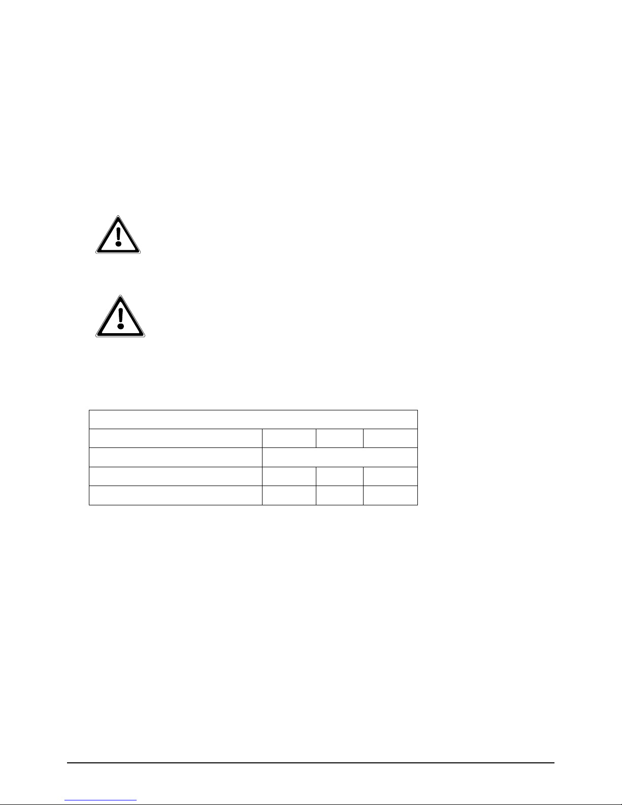
CAUTION:
This symbol identifies all working and operational procedures requiring absolute compliance to
avoid any danger to personnel.
ATTENTION:
This symbol identifies all working and operational procedures requiring absolute compliance to
prevent any damage or disruption to the uninterruptible power supply (UPS) or any of its
components.
NOTE:
This symbol identifies technical requirements and additional information requiring the operator's
attention.
i
Page 7

Wärtsilä JOVYSTAR COMPACT S BAX 5452 - 7 -
2 Description of the System
Ensuring a reliable power supply is one of many major issues when using electronic data processing and process
control systems. The main causes of many interruptions to power supply are:
Spikes produced by switching devices on the mains distribution
High frequency superposition caused by welding machines, fluorescent lights, photocopiers and more
Voltage variations due to fast load variations in big inductive consumers (lifts, transformers, machinery,
etc.)
Voltage failures due to disturbances in the mains supply
Frequency variations caused by the use of separate power supply units
The range of disturbances extends from data corruption to memory leaks and from hardware failure to production
stoppages. Therefore, the quality of the power supply is key to the reliability of electronic data processing
equipment. The perfect solution for a secure, uninterrupted power supply for critical consumers is thus the UPS
(Uninterruptible Power Supply). The UPS:
Generates a constant supply voltage and frequency
Reduces mains disturbances and feedback
Guarantees an uninterruptible power supply to connected consumers for a specified period during a
mains failure
In comparison with conventional power sources such as the mains power supply or generators*, the cutting edge
technology featured in UPS systems in the JOVYSTAR series brings the following outstanding advantages:
Minimum mains feedback caused by active IGBT rectifiers
Three sources of intelligence through two DSPs (Digital Signal Processor) and µC (microprocessor)
Extended communication interfaces
RS232/USB serial interfaces for reading UPS data (standard)
SNMP adapter for remote monitoring, data exchange via a LAN connection (option)
MODBUS adapter for remote monitoring, data transfer using MODBUS protocol via RS485
interface (option)
Parallel slot for parallel redundancy systems, UPS systems communicate data with one another
via CAN bus protocol (option)
Relay card with alarm messages for industrial remote monitoring via floating contacts (option)
*NOTE:
Operation of a UPS or other electronic consumers using a generator assumes that before installing
the complete system the planner has established whether the generator can be used in conjunction
with power electronics.
Some generators are designed such that operation with power electronics consumers is not
possible due to the additional loading with harmonics, power factor and commutation notches. In
some cases faults may occur such as voltage unbalance, a tendency to oscillate and the shutting
down of the generator. It may help to ask the generator manufacturer about this and, if necessary
change the regulator on the generator or incorporate damper windings in the generator from the
outset.
i
Page 8

Wärtsilä JOVYSTAR COMPACT S BAX 5452 - 8 -
2.1 Functional description
The block diagram shows the functional design of a JOVYSTAR UPS. It comprises the component groups
"rectifier", "battery", "inverter", "static switch". The "RCB", "SBCB", "MBCB", "BCB" and "OCB" switches are used
to start and shut down the UPS as well as to switch over to the bypass. Additionally, for maintenance purposes
the battery can be disconnected from the UPS.
Block diagram of a JOVYSTAR UPS
Key to the block diagram
Mains/Bypass → UPS supply
RCB → Rectifier Circuit Breaker
SBCB → Static Bypass Circuit Breaker
MBCB → Manual Bypass Circuit Breaker
BCB → Battery Circuit Breaker
OCB → Output Circuit Breaker
Output → Output for the connection of consumers
2.1.1 Rectifier
The rectifier converts the three-phase mains voltage into a regulated DC voltage to supply the inverter and charge
the batteries. The rectifier comprises the control electronics for charging the battery and IGBT components for
adjusting the power factor.
2.1.2 Inverter
The inverter converts the DC voltage from the rectifier or the battery into a stabilised AC voltage regulated by
pulse width modulation. Due to the fast regulation, the UPS generates an excellent sine -wave voltage with
extremely low distortion that even permits loads with high crest factors. The inverter output is also designed to be
short-circuit proof (electronic short-circuit protection).
2.1.3 Battery
The battery works in standby parallel operation, which means that the inverter, charger and battery are
permanently connected in parallel. To obtain the maximum lifetime of the battery it is protected by floating
operation according to DIN 41773.
2.1.4 Static bypass
Static bypass switches the load without interruption between the inverter and bypass mains input. It comprises a
thyristor bridge for the inverter and another for the bypass. For online operation the inverter output is switched to
the UPS output. In the event of an overload at the output or failure of the inverter, the UPS output continues to be
powered without interruption via the bypass.
2.1.5 Internal, manual bypass
Manual bypass is used to bypass parts of the UPS. In the event of maintenance or repair, the load is supplied
directly from the mains.
Page 9

Wärtsilä JOVYSTAR COMPACT S BAX 5452 - 9 -
2.2 Operating states
2.2.1 Normal operation
Normal operation is divided into two further operating modes. For sensitive loads, online operation via the inverter
provides a stable AC voltage. For loads that are less susceptible to mains fluctuations, eco mode offers a better
efficiency rating.
Online operation
The mains feeds the rectifier.
The rectifier provides the DC voltage for the inverter and charges the batteries.
The inverter supplies the load at the output with the necessary energy via the static switch.
If there is any threat of a deep battery discharge, the system automatically switches to the static bypass
without interruption.
Online operation: load supplied via the inverter
Offline operation:
The mains feeds the rectifier.
The rectifier provides the DC voltage for the inverter and charges the batteries.
The bypass supplies the load at the output with the necessary energy via the static switch.
In the event of a mains failure the system automatically switches to the inverter without interruption.
Offline operation: load supplied via the static bypass
Page 10

Wärtsilä JOVYSTAR COMPACT S BAX 5452 - 10 -
2.2.2 Inverter fault
The mains feeds the rectifier.
The rectifier provides the DC voltage for the inverter and charges the batteries.
The load at the output is transferred to the bypass without interruption via the static switch.
Inverter fault: load supplied via the bypass
2.2.3 Rectifier fault
The mains feeds the rectifier.
The battery provides the DC voltage for the inverter (for the duration of the stored energy time).
The inverter supplies the load at the output with the necessary energy via the static switch.
If there is any threat of a deep battery discharge, the system automatically switches to the static bypass
without interruption.
Rectifier fault: load supplied via the inverter according to the stored energy time of the batteries
Page 11

Wärtsilä JOVYSTAR COMPACT S BAX 5452 - 11 -
2.2.4 Mains failure
The battery provides the DC voltage for the inverter (for the duration of the stored energy time).
The inverter supplies the load at the output with the necessary energy via the static switch.
If there is any threat of a deep battery discharge, the system automatically shuts down completely and
the load is no longer supplied with power.
Mains failure: load supplied via the inverter according to the stored energy time of the batteries
2.2.5 Manual bypass
The load is supplied by the mains via the manual bypass.
Any necessary maintenance or repairs to the UPS can be carried out safely.
Manual bypass load supplied via the manual bypass
Page 12
Wärtsilä JOVYSTAR COMPACT S BAX 5452 - 12 -
3 Installation
Remove the packaging immediately after receiving the UPS and check the system for transport damages. The
transport company must be informed immediately after receipt of the UPS in the event of any damage caused
during transportation. If the UPS is not installed immediately it must be stored in an upright position as indicated
onthe packaging and kept in a dry, well ventilated room. If the UPS is not stored in the original packaging, it must
be protected from dust and moisture.
3.1 Handling of the UPS
The UPS is packed on a pallet. It is handled from the transport vehicle to the installation (or storage) place via a
fork lift.
The device has a heavy weight
Avoid turnover during the transport of the UPS.
Cabinets must always be handled in upright position.
During loading and unloading operations, always respect the indications regarding
the device barycentre marked on the package.
Before positioning the UPS, in order to avoid risks of turnover, it’s recommended to move the system on the wood
pallet on which the UPS is fixed. Before the positioning in the final location, remove the UPS from the pallet.
To handle the UPS remove the lower front, rear and side panels and insert the forks of a fork lift. The UPS can be
handled both from the front and from the side according to the available spaces, as shown by the following
picture.
Page 13
Wärtsilä JOVYSTAR COMPACT S BAX 5452 - 13 -
3.2 Positioning and Installation
The UPS must be installed indoor, in a clean and dry room, preferably without dust or humidity infiltrations. For
the environmental conditions in the place of installation, in compliance with the current legislation, please refer to
the “Overall dimensions, minimum distances from the walls and ventilation” section.
Special environmental conditions
It is necessary to implement specific protective measures in case of unusual environmental
conditions:
harmful smoke, dust, abrasive dust;
humidity, vapour, salt air, bad weather or dripping;
explosive dust and gas mixture;
extreme temperature variations;
bad ventilation;
conductive or radiant heat from other sources;
fungus, insects, vermin.
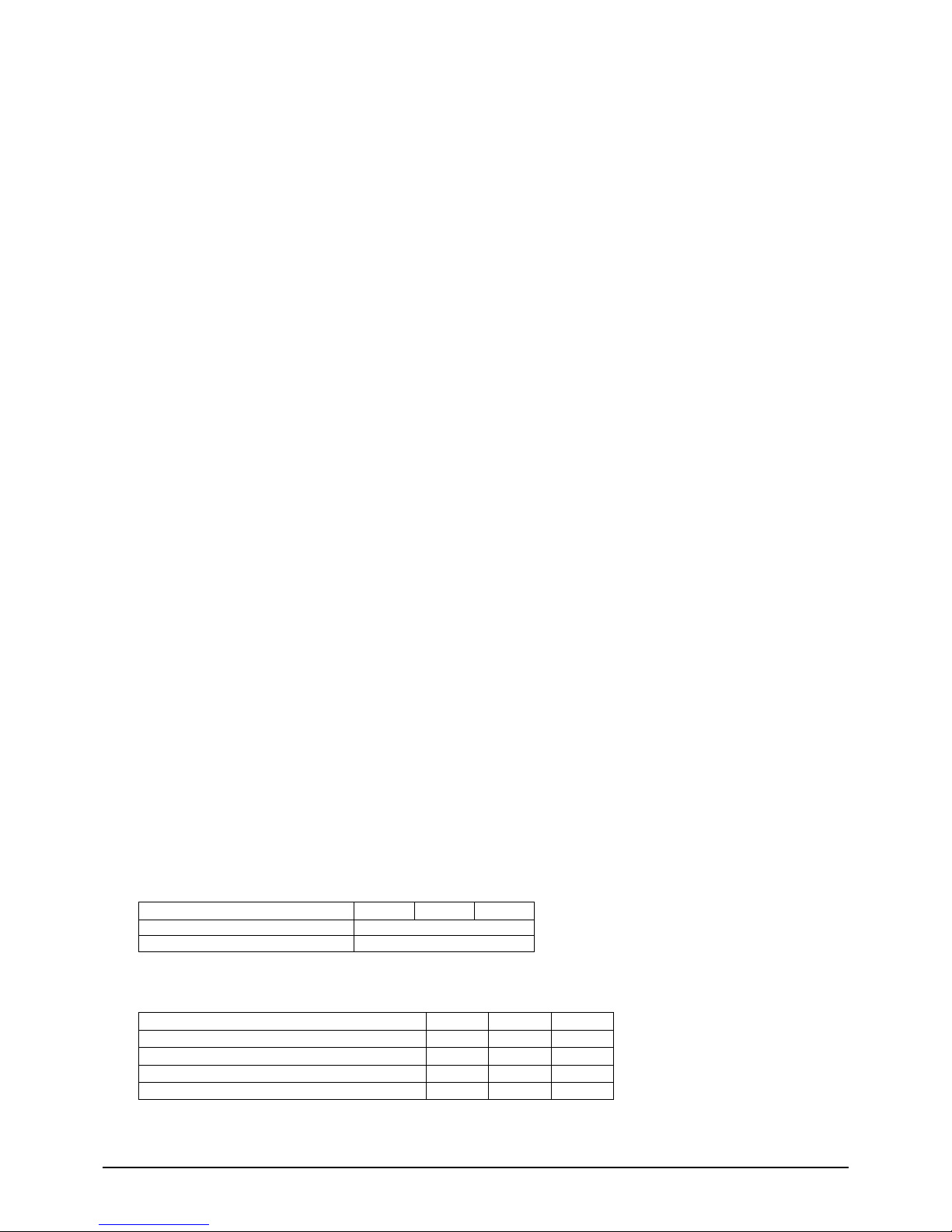
3.2.1 Base Plan, Static Load and Weights
Power (kVA)
30
40
50
L1 – mm
502
P1 – mm
943
The supporting base of the UPS must be designed to carry the UPS weight and to ensure its steady and safe
support. Its carrying capacity must be adequate to the static loads indicated in the table below.
Power (kVA)
30
40
50
Weight w/o batteries (kg)
140
150
190
Static load w/o batteries (kg/m^2)
500
510
550
Weight with batteries (kg)
310
335
425
Static load with batteries (kg/m^2)
1110
1135
1225
Page 14
Wärtsilä JOVYSTAR COMPACT S BAX 5452 - 14 -
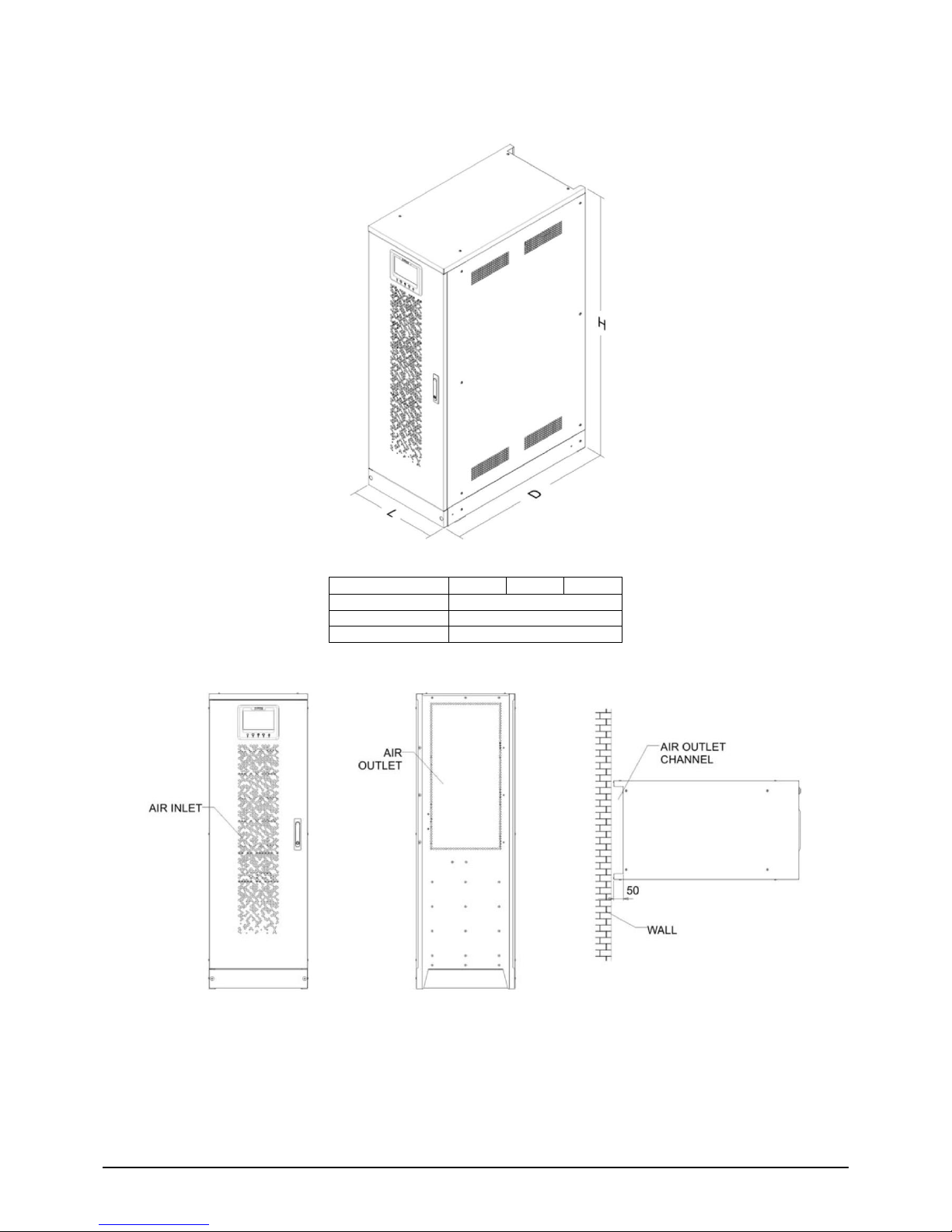
3.2.2 Overall Dimensions, Clearances and Ventilation
Leistung (kVA)
30
40
50
L – mm
505
D – mm
940
H – mm
1505
Page 15
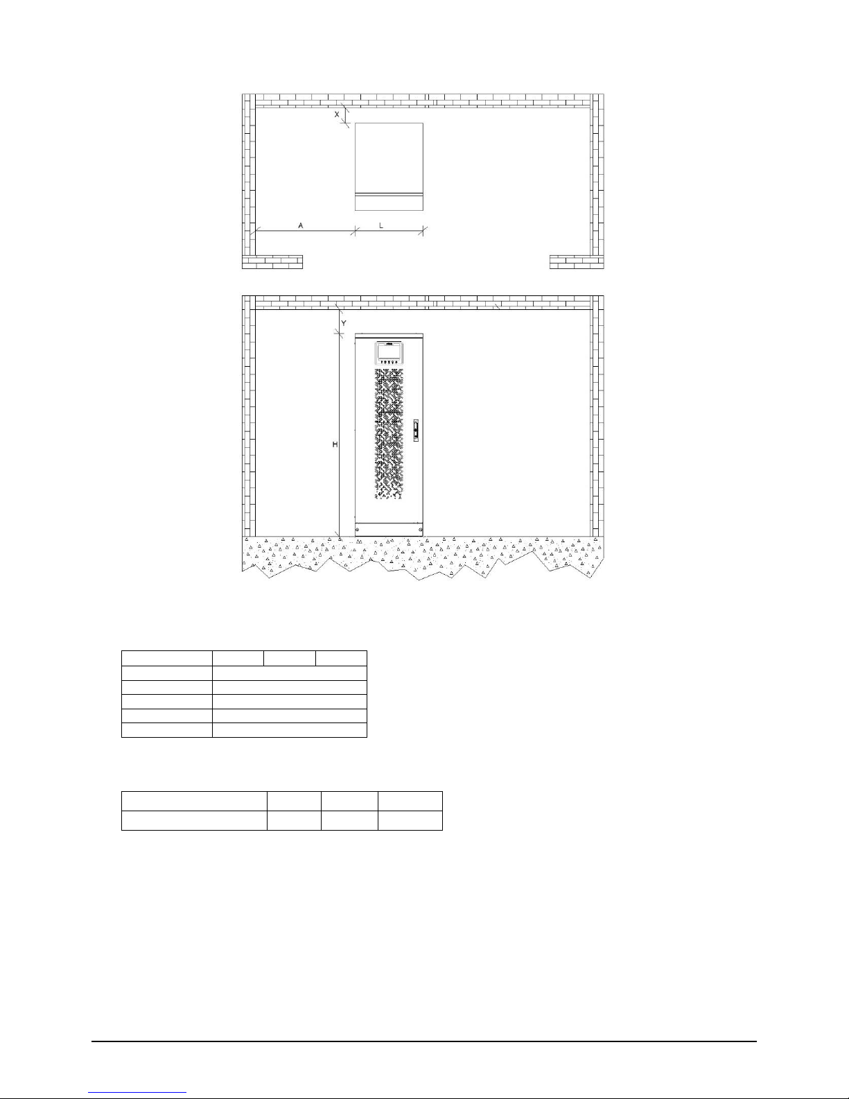
Wärtsilä JOVYSTAR COMPACT S BAX 5452 - 15 -
The UPS must be so installed as to ensure its serviceability and to allow a correct air flow as much as possible.
With regard to the minimum distances from the walls, for all of the UPS sizes the same installation conditions
apply as indicated in the table below.
Power (kVA)
30
40
50
L – mm
505
H – mm
1505
X (min.) - mm
0
Y (min.) – mm
500
A (min.) – mm
500*
*Only required at installed battery inside the UPS (Battery exchange)!
The table below shows the air volume required for an optimal ventilation and cooling of the UPS.
Power (kVA)
30
40
50
Air volume (m3/h)
900
900
1100
Page 16

Wärtsilä JOVYSTAR COMPACT S BAX 5452 - 16 -
3.2.3 Environmental Installation Conditions
The air is classified by the EN 60721-3-3 standard (Classification of environmental parameters and their severities
– Stationary use at weather-protected locations) based on climatic and biological conditions as well as on
mechanically and chemically active substances.
Therefore the place of installation must meet specific requirements to ensure compliance with the conditions for
which the UPS was designed.
Climatic conditions according to the technical specification
Environmental parameter
Minimum operating temperature (°C)
– 10
Maximum operating temperature (°C)
+ 40
Minimum relative humidity (%)
5
Maximum relative humidity (%)
95
Condensation
NO
Rainfall with wind (rain, snow, hail, etc.)
NO
Water with an origin other than rain
NO
Ice formation
NO
The UPS is designed to be installed in an environment that meets the following classifications.
K
Climatic conditions
In accordance with the technical specification
B
Biological conditions
3B1 (EN 60721-3-3)
C
Chemically active substances
3C2 (EN 60721-3-3)
S
Mechanically active substances
3S2 (EN 60721-3-3)
In the event that the environmental conditions of the installation room do not comply with the specified
requirements, additional precautions must be taken to reduce excessive values to the specified limits.
Page 17
Wärtsilä JOVYSTAR COMPACT S BAX 5452 - 17 -
3.3 Electrical connections, cross sections, fuses
The electrical connection of the UPS unit is the task of the electrician providing the electrical installation services.
This task is not carried out by the UPS manufacturer. For this reason, the following recommendations are only an
indication, as the UPS manufacturer isnot responsible for the electrical installation.
In all cases we recommend carrying out the installation and the electrical connections to the UPS in accordance
with local regulations and standards. Take particular care during electrical installation to ensure a clockwise
rotating phase sequence. In the event that strong electromagnetic fields are emitted, we recommend the use of
shielded cables between the UPS and the load.
In accordance with EN 62040-1, mains backfeed protection has to be provided for the UPS, preventing a current
flow from the output of the UPS back into the mains at a single fault of the system. Therefore it is necessary to
install a separator in the power supply for the bypass, which the bypass current path separates automatically in
case of a failure of the bypass mains.
ATTENTION:
Even when the mains voltage is switched off there is a dangerously high battery voltage inside the
device. All installations and connections may therefore only be carried out by qualified
electricians. Before commencing work, electricians must read this manual carefully to familiarize
themselves with the special features of this UPS unit. The UPS output still carries voltage even in
the event of a mains failure. For this reason, the installer must clearly label the outlets and
sockets on the UPS unit in accordance with EN 62040!
ATTENTION:
The input line between the mains and the UPS unit must be protected against short circuits!
The use of FI safety switches before the UPS unit is not recommended.
3.3.1 Fuses and cross sections for cable connections to the UPS
Should larger cable cross-sections be required for the installation than the maximum cross-section of the UPS
terminals, a socket or a terminal box can be installed near the UPS. From there to the UPS, a cable laying with a
smaller cross-section can be possible (better laying conditions such as installation type, cable length, ...).
Details der elektrischen Anschlüsse
Leistung (kVA)
30
40
50
Input fuses [A]
Rectifier
63
80
100
Bypass
63
80
100
Page 18

Wärtsilä JOVYSTAR COMPACT S BAX 5452 - 18 -
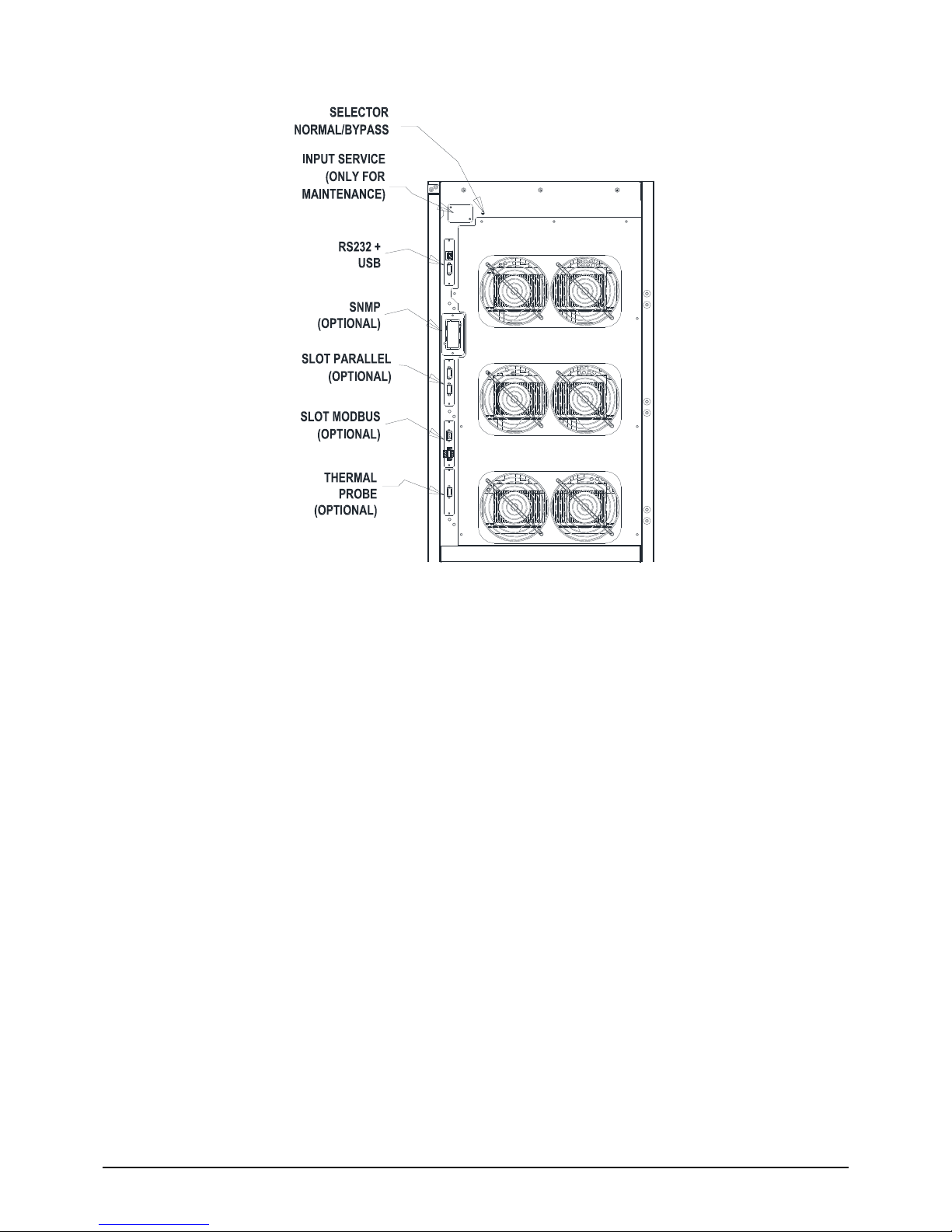
3.3.2 Connections to the UPS
30/40kVA
50kVA
Max. 25mm²
4 - 4,5Nm
Max. 25mm²
4 - 4,5Nm
Max. 35mm²
2,8 - 3Nm
Max. 4mm²
0,5 - 0,8Nm
Bolt M6
8,3 - 11,1Nm
Max. 35mm²
4 - 4,5Nm
Max. 35mm²
4 - 4,5Nm
Max. 35mm²
2,8 - 3Nm
Max. 4mm²
0,5 - 0,8Nm
Bolt M6
8,3 - 11,1Nm
PE BOLT
M8, 9 Nm
PE BOLT
M8, 9 Nm
Page 19
Wärtsilä JOVYSTAR COMPACT S BAX 5452 - 19 -
3.3.3 UPS-Options (Optional equipment)
Following UPS-Options are described in the operating manual BAX 4834:
Relay card
SNMP adapter
PROFIBUS
MODBUS
Battery symmetry supervision
Parallel redundant systems
Page 20
Wärtsilä JOVYSTAR COMPACT S BAX 5452 - 20 -
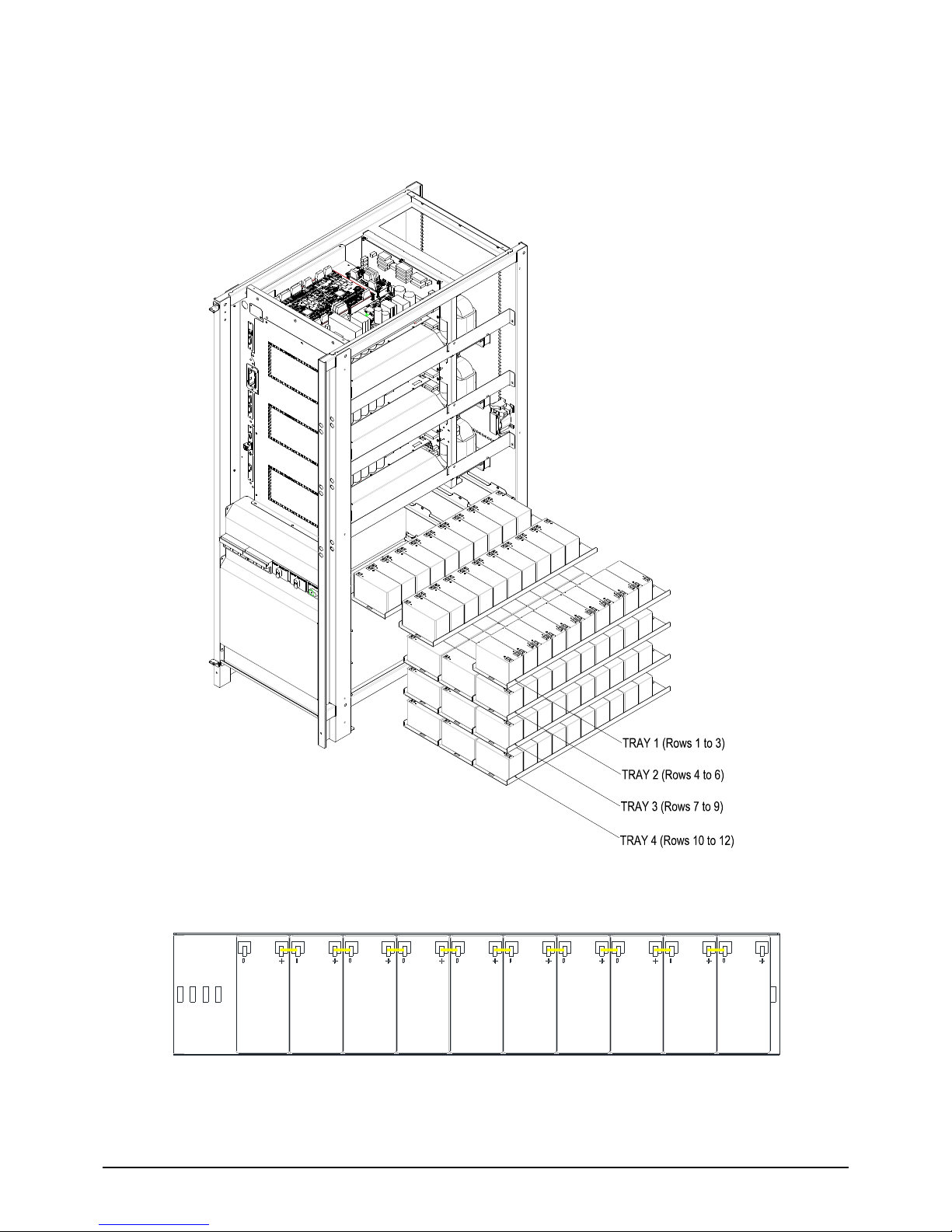
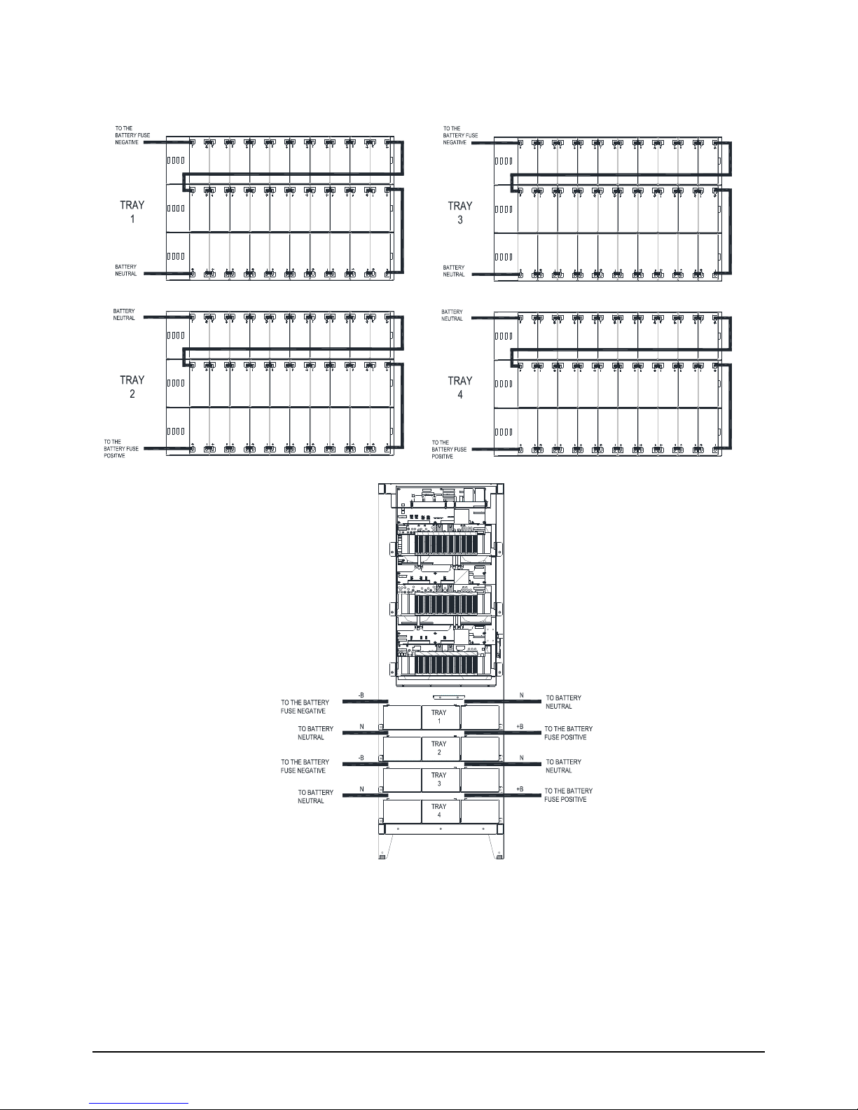
3.3.4 Mounting and connecting the battery
3.3.4.1 Battery 7/9/11Ah 12V installation
1) Remove the 4 screws to open the left/right lateral cover and access the battery trays
(total trays are 4 and each contain three rows of 10 batteries, see picture).
Trays 7/9/11Ah 12V battery lateral view
One raw 7/9/11Ah 12V battery top view
Page 21
Wärtsilä JOVYSTAR COMPACT S BAX 5452 - 21 -
2) Install the batteries received in a separate packages and install it in accordance with the picture 11 and picture
12.
7/9/11Ah 12V battery connection tray top view
7/9/11Ah 12V battery connection tray front view
3) After the connection re-insert the battery trays on the internal of UPS.
4) Put back and fix the left/right cover with the four screws.
Page 22

Wärtsilä JOVYSTAR COMPACT S BAX 5452 - 22 -
Page 23

Wärtsilä JOVYSTAR COMPACT S BAX 5452 - 23 -
4 Operation
4.1 Front Panel
The front panel of the UPS, consisting of four rows alphanumeric display plus 5 function keys, allows the
complete monitoring of the UPS status.
The mimic flow helps to understand the operating status of the UPS.
UPS front panel
Page 24
Wärtsilä JOVYSTAR COMPACT S BAX 5452 - 24 -
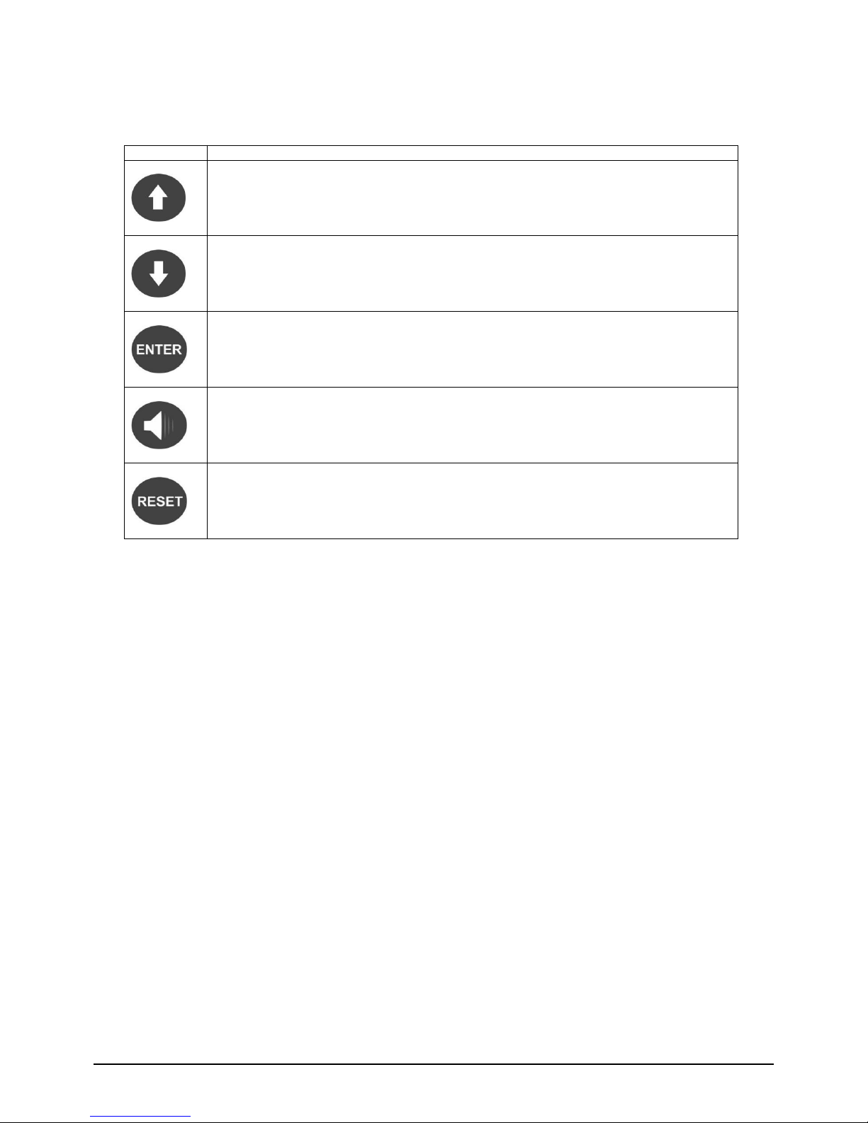
4.1.1 Function Buttons
The front panel of the UPS is provided with 5 buttons whose functions are indicated in the following table:
Button
Assigned functions
Scrolls up the menus
Increases the values by one unit
Selects a value
Scrolls down the menus
Decreases the values by one unit
Selects a value
Selects a menu
Confirms changes
Silences the buzzer (activated due to an alarm or a failure)
Returns to the previous menu
Page 25

Wärtsilä JOVYSTAR COMPACT S BAX 5452 - 25 -
4.1.2 Mimic Panel / LED
UPS mimic panel
LED 1
GREEN
AC line on rectifier input within tolerance
GREEN
AC mains failure / Wrong phase rotation
LED 2
GREEN
AC bypass line within tolerance
GREEN
Wrong phase rotation
OFF
AC bypass line out of tolerance / failure
LED 3
GREEN
Rectifier off or faulty
RED
DC voltage out of tolerance
GREEN
Rectifier on and DC voltage within tolerance
LED 4
GREEN
Circuit breaker BCB closed and battery charging
GREEN
Battery discharging or under TEST
ORANGE
Circuit breaker BCB open
RED
Battery fault (following a battery test)
OFF
Battery not available
LED 5
GREEN
Inverter voltage within tolerance and static switch closed
GREEN
Inverter overload or short-circuit
OFF
Inverter off or voltage out of tolerance
LED 6
ORANGE
Re-transfer blocked
ORANGE
Static bypass switch closed
OFF
Static bypass switch open
LED 7
GREEN
Output circuit breaker OCB closed
OFF
Output circuit breaker OCB open
LED 8
ORANGE
Manual bypass switch MBCB closed
OFF
Manual bypass switch MBCB open
LED 9
RED
Emergency power off (EPO) activated
OFF
Normal operation
LED 10
ORANGE
Maintenance request (slow blinking)
ORANGE
Critical alarm (fast blinking)
OFF
Normal operation
Page 26

Wärtsilä JOVYSTAR COMPACT S BAX 5452 - 26 -
4.1.3 LED-Bar
LED bar
LED 11
GREEN
AC line on rectifier input within tolerance
GREEN
Wrong phase rotation (fast blinking)
GREEN
Unbalanced AC voltage (slow blinking)
OFF
AC mains failure
LED 12
GREEN
Circuit breaker BCB closed and battery charging
ORANGE
Battery discharging or under TEST (fast blinking)
ORANGE
Circuit breaker BCB open (slow blinking)
RED
End of battery autonomy / Battery fault
LED 13
GREEN
Inverter voltage within tolerance and static switch closed
ORANGE
Inverter overload or short-circuit
RED
Inverter critical alarm
OFF
Inverter off
LED 14
GREEN
AC bypass line within tolerance
RED
Wrong phase rotation (fast blinking)
RED
AC bypass line out of tolerance / failure
LED 15
GREEN
Programmed maintenance required (slow blinking)
GREEN
Critical alarm (fast blinking)
Page 27

Wärtsilä JOVYSTAR COMPACT S BAX 5452 - 27 -
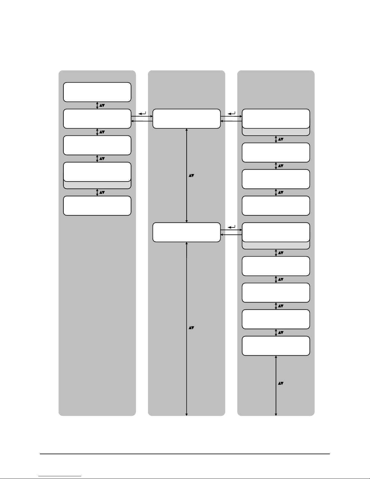
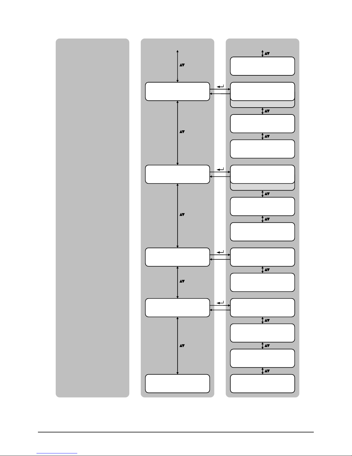
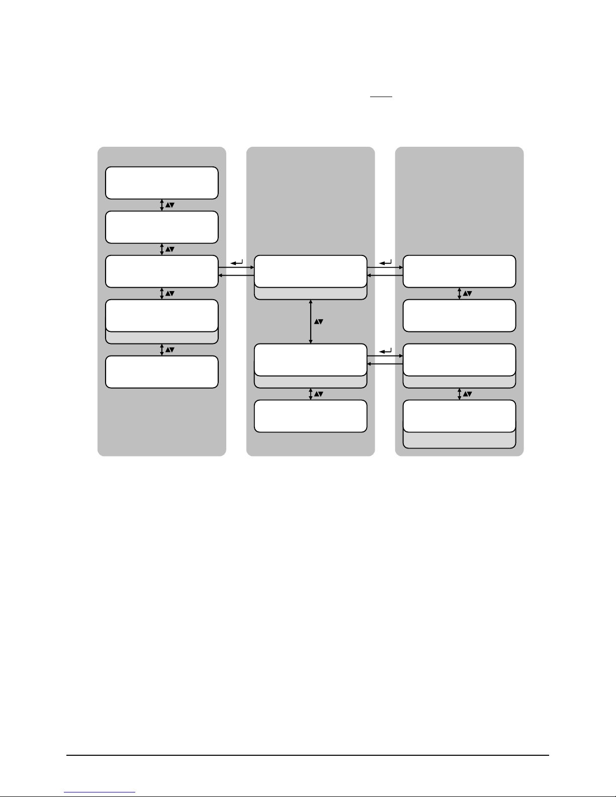
4.2 Menu structure
The following figure shows the complete structure in a clear format. The main menu is divided into four areas:
"Measures", "Alarms", "Special" and "Info" This means the required information/reports and measures can be
displayed quickly and various settings made. Details of the options available are given in the sections below.
JOVYSTAR
MEASURES
INPUT
OUTPUT
BYPASS
INVERTER
AC / DC
BATTERY
ALARMS
UPS STATUS
HISTORY
SPECIAL
RESET
CLOCK SETTINGS
SELECT LANGUAGE
UPS TEST
BATTERY SETTING
BATTERY TEST
NEW BATTERY
INSTALL
RESET HISTORY
MODBUS
RESET RUNNING
HOURS
INFO
SERIAL NUMBER
DEVICE TYPE
PARALLEL
MODBUS
FIRMWARE
RELEASE
SERVICE
RUNNING HOURS
Page 28
Wärtsilä JOVYSTAR COMPACT S BAX 5452 - 28 -
4.2.1 Measures
The measured data of the UPS are saved in the main menu under “Measures”. It can be displayed the input,
output and bypass values, as well as data about the assemblies rectifier, inverter and battery.
„UPS-NAME“
MEASURES
„UPS-NAME“
ALARMS
Password-entry is required!
„UPS-NAME“
SPECIAL
„UPS-NAME“
INFO
Sub menu
Display
Voltage is based on N-connector
MEASURES
INPUT
INPUT VOLT/CURR
xxx yyy zzz V
INPUT FREQUENCY
xx.x Hz
INPUT POWER
xxx kVA
INPUT
EXIT
Main menu
„UPS-NAME“
xxx kVA
RES
RES
Voltage is based on N-connector
MEASURES
OUTPUT
OUTPUT VOLT/CURR
xxx yyy zzz V
OUTPUT FREQUENCY
xx.x Hz
OUTPUT POWER
xxx kW
OUTPUT POWER
yyy kVA
LOAD
xxx yyy zzz %
RES
Page 29
Wärtsilä JOVYSTAR COMPACT S BAX 5452 - 29 -
Sub menu
Display
Voltage is based on N-connector
MEASURES
BYPASS
BYPASS VOLTAGE
xxx yyy zzz V
BYPASS
EXIT
Main menu
BYPASS FREQUENCY
xx.x Hz
RESET
Voltage is based on N-connector
MEASURES
INVERTER
INVERTER VOLT/CURR
xxx yyy zzz V
INVERTER
EXIT
INVERTER FREQUENCY
xx.x Hz
RESET
MEASURES
AC / DC
AC / DC VOLTAGE
xxx V
AC / DC
EXIT
RESET
MEASURES
BATTERY
BATTERY VOLT/CURR
xxx V xxx A
BATTERY AUTONOMY
xxx Min yyy %
BATTERY TYPE
xx.x Ah
RESET
BATTERY
EXIT
MEASURES
EXIT
OUTPUT
EXIT
Page 30
Wärtsilä JOVYSTAR COMPACT S BAX 5452 - 30 -
4.2.2 Alarms
The menu “Alarms” displays the status of the UPS and the alarms. All active alarms and status reports will be
displayed in the sub menu „UPS Status“. If a fault occurs, the status menu automatically appears and presents
the relevant report on the display. In addition, an acoustic signal will sound, which can be disabled by pressing the
buzzer button. Occurred and removed faults are saved and can be displayed in the sub menu „History“ at any
time.
(See also list of status reports)
(See also list of alarms)
Star (*) next to fault code means:
Fault was removed at the specified time
„UPS-NAME“
MEASURES
„UPS-NAME“
ALARMS
Password-entry is required!
„UPS-NAME“
SPECIAL
„UPS-NAME“
INFO
Sub menu
Display
ALARMS
UPS STATUS
USV STATUS
(First status report)
Main menu
„UPS-NAME“
xxx kVA
USV STATUS
(Last status report)
RESET
RESET
Fault was detected at the specified time
ALARMS
HISTORY
HISTORY
HISTORY: xxx/yyyy
Code Date/Time
HISTORY
HISTORY: xxx/yyyy
Code* DATE/TIME
RESET
ALARMS
EXIT
Page 31

Wärtsilä JOVYSTAR COMPACT S BAX 5452 - 31 -
4.2.3 Special
Different settings to the UPS can be made in the „Special“-menu. For that a password entry is necessary, to
prevent a change of the system data by unauthorized persons. Then the following settings can be made:
Reset of the UPS, set Date/Time, select language, perform an UPS test, enter battery data, perform a battery
test, install new battery, delete history, set modbus address and reset running time.
UPS automatically switches from Inverter
mode to bypass mode and returns
Caution: In bypass fault, an
immediately inverter operating during
the test phase cannot be guaranteed! A
failure of the load is possible!
Change language of the display output
Set date and time
„UPS-NAME“
MEASURES
„UPS-NAME“
ALARMS
Password-entry is required!
„UPS-NAME“
SPECIAL
„UPS-NAME“
INFO
Sub menu
Display
Main menu
„UPS-NAME“
xxx kVA
RESET
SPECIAL
CLOCK SETTINGS
CURSOR-Keys: Selection of a digit (0-9)
RETURN: Confirmation of a digit
RESET: Cancel current selection of digit
and back to previous digit
CLOCK SETTINGS
DD-MM-YY hh:mm
SPECIAL
SELECT LANGUAGE
CURSOR-Keys: Selection of the language
RETURN: Confirmation of the language
More languages
2 – DEUTSCH, 3 – F RANCAIS,
4 – ENGLISH, 5 – PORTUGUES,
6 – ESPANOL, 7 – POLSKI,
8 – TURKCE
SELECT LANGUAGE
1 – ITALIANO
Note: Lower interventions are made in
the system
(Input wrong password: Exit)
CURSOR-Keys: change digit
RETURN: Confirmation of a digit
ENTER PASSWORD
123
Reset of the UPS: Active fault conditions
are reset
SPECIAL
RESET
CURSOR-Keys: Selection YES/NO
RETURN: Confirmation YES/NO
RESET DEVICE?
YES / NO
RESET
RESET
RESET
SPECIAL
UPS TEST
CURSOR-Keys: Selection YES/NO
RETURN: Confirmation YES/NO
UPS TEST
YES / NO
RESET
Page 32

Wärtsilä JOVYSTAR COMPACT S BAX 5452 - 32 -
Caution: The test can affect the supply
of the load if the battery is not fully
charged
Short discharge test of the battery;
„Battery fault“ appears, if battery not O.K.
Set the battery properties:
Capacity, charging current, autonomy time
Sub menu
Display
Main menu
CURSOR-Keys: Selection YES/NO
RETURN: Confirmation YES/NO
CONFIRM AUTON BATT?
YES / NO
CURSOR-Keys: Selection YES/NO
RETURN: Confirmation YES/NO
SAVE BATT SETTINGS?
YES / NO
BATT SETTINGS SAVED
SPECIAL
BATTERY SETTING
CURSOR-Keys: Selection of a digit (0-9)
RETURN: Confirmation of a digit
RESET: Cancel current selection of digit
and back to previous digit
BAT CAPACITY SETTING
xxx.x Ah
CURSOR-Keys: Selection YES/NO
RETURN: Confirmation YES/NO
CONFIRM BATT CAP.?
YES / NO
CURSOR-Keys: Selection of a digit (0-9)
RETURN: Confirmation of a digit
RESET: Cancel current selection of digit
and back to previous digit
BAT RECHAR CURR SET
xx.x A
CURSOR-Keys: Selection YES/NO
RETURN: Confirmation YES/NO
CONFIRM RECHAR CURR?
YES / NO
CURSOR-Keys: Selection of a digit (0-9)
RETURN: Confirmation of a digit
RESET: Cancel current selection of digit
and back to previous digit
AUTONOMY BAT SETTING
xxxx min
RESET
(4x)
(2x)
(4x)
SPECIAL
BATTERY TEST
CURSOR-Keys: Selection YES/NO
RETURN: Confirmation YES/NO
BATTERY TEST?
YES / NO
RESET
Page 33

Wärtsilä JOVYSTAR COMPACT S BAX 5452 - 33 -
Reset running time to zero
Set modbus address
Delete history
Sub menu
Display
Main menu
SPECIAL
RESET RUNNING HOURS
SPECIAL
EXIT
CURSOR-Keys: Selection YES/NO
RETURN: Confirmation YES/NO
RESET HISTORY?
YES / NO
SPECIAL
RESET HISTORY
SPECIAL
MODBUS
CURSOR-Keys: Selection of a digit (0-9)
RETURN: Confirmation of a digit
RESET: Cancel current selection of digit
and back to previous digit
(Address range: 1… 247)
MODBUS ADDRESS
xxx
CURSOR-Keys: Selection YES/NO
RETURN: Confirmation YES/NO
RESET RUNNING HOURS?
YES / NO
RESET
RESET
RESET
Set autonomy time of the new installed
battery to 100 %
CURSOR-Keys: Selection YES/NO
RETURN: Confirmation YES/NO
SPECIAL
NEW BATTERY INSTALL
NEW BATTERY INSTAL?
YES / NO
RESET
Page 34

Wärtsilä JOVYSTAR COMPACT S BAX 5452 - 34 -
4.2.4 Info
The menu „Info“ include all relevant information of the UPS as the serial numbers (Device and job number), the
device type (Online-/Eco mode and single or parallel system), the device data at a parallel system (Only active, if
available), the modbus address, the versions of the installed firmware, the service remark (Only active, if
available) and the running time.
„UPS-NAME“
MEASURES
„UPS-NAME“
ALARMS
Password-entry is required!
„UPS-NAME“
SPECIAL
„UPS-NAME“
INFO
Sub menu
Display
Main menu
„UPS-NAME“
xxx kVA
RESET
INFO
DEVICE TYPE
Display the device serial number
UPS SERIAL NUMBER
xxxxxxxxxx
Display the job number
OEM SERIAL-NUMBER
xxxxxxxxxx
SERIAL-NUMBER
EXIT
INFO
SERIAL NUMBER
Possibility: On Line/Eco mode
DEVICE TYPE
UPS – ON LINE
Possibility: Single/Parallel
DEVICE TYPE
SINGLE
RESET
RESET
DEVICE TYPE
EXIT
Page 35

Wärtsilä JOVYSTAR COMPACT S BAX 5452 - 35 -
CAN bus statistic static switch:
Number of received data and number of
correctly received data in percent
All UPS devices send data;
All UPS devices receive data
Sub menu
Display
Main menu
Parallel menu only visible, if the UPS
belongs to a parallel system!
POWER: All UPS devices supply the load
REDUNDANT+X: X = Number of the UPS
devices in the parallel-standby mode
Digit = Device number in the parallel
system; M = Master, S = Slave;
? = No communication exists on the data
bus in the parallel system;
[ ] = Identify position/configuration of the
current UPS in the parallel system
Position of the current UPS in the parallel
system/Number of UPS devices in the
parallel system
PARALLEL
x / y
Possibility: Master/Slave
Only a master possible, or faults in the data
communication bus
PARALLEL
MASTER
PARALLEL
EXIT
INFO
PARALLEL
PARALLEL
1- S 2- M 3-[S] 4- ?
PARALLEL
REDUNDANT+X
PARALLEL
CAN STATISTICS SSW
MSG RX: xxxxx xxx.x%
RESET
CAN bus inverter:
Number of received data and number of
correctly received data in percent
Only the master sends data;
Only the slaves receive data
PARALLEL
CAN STATISTICS INV
SYNC RX: xxxxx xxx.x%
CAN bus inverter:
Number of received data and number of
correctly received data in percent
All UPS devices send data;
All UPS devices receive data
PARALLEL
CAN STATISTIK INV
MSG RX: xxxxx xxx.x%
Display the modbus address
INFO
MODBUS
Settable address range: 1… 247
MODBUS
ADDRESS: xxx
RESET
Page 36

Wärtsilä JOVYSTAR COMPACT S BAX 5452 - 36 -
See contact details/inform Technical
Support Service
Service menu only visible, if a service
remark is active
Sub menu
Display
Main menu
See contact data/Notify the service
INFO
SERVICE
FIRMWARE RELEASE
EXIT
SERVICE
---------- Sliding text ----------
SERVICE
EXIT
INFO
RUNNING HOURS
RUNNING HOURS
xxxxxx
RUNNING HOURS
EXIT
Microcontroller of the static switch
FIRMWARE RELEASE
uC S: vv.xx.yy.zz
RESET
RESET
INFO
EXIT
Digital signal processor of the inverter
Digital signal processor of the rectifier
INFO
FIRMWARE RELEASE
FIRMWARE RELEASE
DSP1 R: vv.xx.yy.zz
FIRMWARE RELEASE
DSP2 I: vv.xx.yy.zz
RESET
MODBUS
EXIT
Page 37

Wärtsilä JOVYSTAR COMPACT S BAX 5452 - 37 -
4.3 Alarm messages and status reports in the display
The status reports describe the operating condition of individual components, whereas alarm messages indicate
special states or faults described in detail below. The descriptions of alarm messages additionally show possible
causes and recommend initial actions that may be taken to resolve the problem.
4.3.1 Description of status reports
Status
S1
RECTIFIER OK
Description
The rectifier section is working properly
Operating condition
The rectifier supplies the inverter and keeps the battery charged
Status
S2
BATTERY OK
Description
The battery is connected to the UPS
Operating condition
The battery is kept charged by the rectifier and is ready to feed the inverter
Status
S3
INVERTER OK
Description
The inverter voltage and frequency are within the allowed range
Operating condition
The inverter is ready to feed the load
Status
S4
INVERTER FEEDS LOAD (Only in Online-mode)
Description
The inverter feeds the load
Operating condition
The load is fed via the static inverter switch
Status
S5
INVERTER BYPASS SYNCHRONIZATION
Description
The inverter is synchronized with the bypass
Operating condition
The synchronization between the inverter and the bypass is locked, and the static switch can change over from one source
to the other.
Status
S6
BYPASS OK
Description
The bypass voltage and frequency are within the allowed range
Operating condition
The bypass line is ready for changeover in case of inverter failure
Status
S7
BYPASS FEEDS LOAD (Only in ECO-mode)
Description
Load fed by the bypass line
Operating condition
The load is fed by the bypass via the static switch, waiting for the inverter to restart
Status
S8
BOOST CHARGE
Description
The battery is in BOOST charge
Operating condition
The rectifier is charging the battery with a higher voltage. The return to FLOATING charge mode is automatic.
Status
S9
MASTER INVERTER SYNCHRONIZATION
Description
The inverter is synchronized with the MASTER UPS
Operating condition
This status is only present on the SLAVE UPS units, and shows that the inverter is synchronized with the signal sent by the
MASTER UPS
Page 38

Wärtsilä JOVYSTAR COMPACT S BAX 5452 - 38 -
4.3.2 Description of alarm messages
Alarm
A1
MAINS FAILURE
Description
The voltage or frequency of the input line is out of tolerance.
Possible causes
Mains instability or failure.
Wrong phase rotation.
Solutions
1. Check the connections to the mains.
2. Check the stability of mains voltage.
3. If the alarm persists, contact our Technical Support Service.
Alarm
A2
INPUT PHASE ROTATION NOT CORRECT
Description
The phase rotation on the rectifier input line is wrong.
Possible causes
Wrong connection of power cables.
Solutions
1. Check the phase rotation.
2. If the alarm persists, contact our Technical Support Service.
Alarm
A3
RECTIFIER OFF
Description
The rectifier has been temporarily disconnected and the inverter is fed by the battery.
Possible causes
Instability of the AC line voltage or frequency.
Possible fault in the rectifier control circuit.
Solutions
1. Check the parameters of the AC line voltage.
2. Restart the device.
3. If the alarm persists, contact our Technical Support Service.
Alarm
A4
RECTIFIER FAILURE
Description
The rectifier has been disconnected due to an internal fault.
Possible causes
Possible fault in the rectifier control circuit.
Solutions
1. Check which alarms are present and carry out the indicated procedures.
2. Restart the device.
3. If the alarm persists, contact our Technical Support Service.
Alarm
A5
WRONG DC VOLTAGE
Description
The measured DC voltage is out of tolerance.
Possible causes
The battery has reached the discharge voltage due to a power failure.
Measuring circuit failure.
Solutions
1. Check the actual value of the measured DC voltage.
2. In case of mains failure, wait for the AC voltage to be restored.
3. Check which alarms are present and carry out the indicated procedures.
4. Restart the device.
5. If the alarm persists, contact our Technical Support Service.
Alarm
A6
BATTERY IN TEST
Description
The rectifier voltage is reduced to start a short controlled discharge of the battery.
Possible causes
A battery test has been started automaticall y (if set), or manually by the user.
Solutions
1. Wait for the test to end, and check possible battery faults.
Alarm
A7
BCB OPEN
Description
The battery isolator is open.
Possible causes
Battery isolator open.
Solutions
1. Check the status of the battery isolator.
2. Check the functionality of the auxiliary contact of the isolator.
3. Check the connection between the auxiliary contact of the isolator and the auxiliary terminals of the UPS (if provided).
4. If the alarm persists, contact our Technical Support Service.
Alarm
A8
BATTERY DISCHARGING
Description
The battery is discharging.
Possible causes
The battery is discharging due to a mains failure.
Rectifier failure.
Solutions
1. Check which alarms are present and carry out the indicated procedures.
2. If the alarm persists, contact our Technical Support Service.
Alarm
A9
BATTERY AUTONOMY END
Description
The battery has reached the pre-alarm discharge level.
Possible causes
The battery is discharging due to a mains failure.
Rectifier failure.
Solutions
1. Check which alarms are present and carry out the indicated procedures.
2. If the alarm persists, contact our Technical Support Service.
Alarm
A10
BATTERY FAULT
Description
Fault following a battery test.
Possible causes
Battery fault.
Solutions
1. Check the battery.
2. Reset the system.
3. If the alarm persists, contact our Technical Support Service.
Page 39

Wärtsilä JOVYSTAR COMPACT S BAX 5452 - 39 -
Alarm
A11
SHORT-CIRCUIT
Description
The current sensor has detected a short-circuit at the output.
Possible causes
Load problem.
Measuring circuit failure.
Solutions
1. Check the loads connected to the UPS output.
2. If the alarm persists, contact our Technical Support Service.
Alarm
A12
SHORT-CIRCUIT TIMEOUT STOP
Description
Inverter shutdown due to an extended short-circuit during a power failure, or due to an over current on the inverter
bridge input.
Possible causes
Short-circuit on the loads during a power failure.
Inverter bridge fault.
Temporary current peak.
Solutions
1. Reset the system.
2. If the alarm persists, contact our Technical Support Service.
Alarm
A13
INVERTER OUT OF TOLERANCE
Description
The inverter voltage or frequency is out of tolerance.
Possible causes
Inverter shutdown due to an alarm.
Inverter failure.
Solutions
1. Check which alarms are present and carry out the indicated procedures.
2. If the alarm persists, contact our Technical Support Service.
Alarm
A14
BYPASS PHASE ROTATION NOT CORRECT
Description
The phase rotation of the bypass line is wrong.
Possible causes
Wrong connection of power cables.
Solutions
1. Check the phase rotation.
2. If the alarm persists, contact our Technical Support Service.
Alarm
A15
BYPASS FAILURE
Description
The voltage or frequency of the bypass line is out of tolerance.
Possible causes
Bypass line instability or failure.
Wrong phase rotation.
Solutions
1. Check the connections to the mains.
2. Check the stability of mains voltage.
3. If the alarm persists, contact our Technical Support Service.
Alarm
A16
BYPASS FEEDS LOAD (Only in Online-mode)
Description
The load is fed by the bypass line.
Possible causes
Temporary changeover due to inverter failure.
Solutions
1. Verify the inverter status and check whether other alarms are present.
2. If the alarm persists, contact our Technical Support Service.
Alarm
A17
RE-TRANSFER BLOCKED
Description
The load is blocked on the bypass line.
Possible causes
Very frequent changeovers due to load in-rush currents.
Static switch problems.
Solutions
1. Reset the system.
2. Check the in-rush currents of the loads.
3. If the alarm persists, contact our Technical Support Service.
Alarm
A18
MBCB CLOSED
Description
The manual bypass isolator is closed.
Possible causes
Manual bypass isolator closed.
Solutions
1. Check the status of the manual bypass isolator.
2. Check the functionality of the auxiliary contact of the isolator.
3. If the alarm persists, contact our Technical Support Service.
Alarm
A19
OCB OPEN
Description
The output isolator is open.
Possible causes
Output isolator open.
Solutions
1. Check the status of the output isolator.
2. Check the functionality of the auxiliary contact of the isolator.
3. If the alarm persists, contact our Technical Support Service.
Alarm
A20
OVERLOAD
Description
The current sensor has detected an overload at the output. If the alarm persists, the thermal image protection will be
activated (alarm A21).
Possible causes
Output overload.
Measuring circuit failure.
Solutions
1. Check the loads connected to the UPS output.
2. Contact our Technical Support Service.
Page 40

Wärtsilä JOVYSTAR COMPACT S BAX 5452 - 40 -
Alarm
A21
THERMAL IMAGE
Description
The thermal image protection has been activated after an extended inverter overload. The inverter is shut down for 30
minutes and then restarted.
Possible causes
Output overload.
Measuring circuit failure.
Solutions
1. Check the loads connected to the UPS output.
2. Should you need to restore the inverter supply immediately, reset the system.
3. If the alarm persists, contact our Technical Support Service.
Alarm
A22
BYPASS SWITCH
Description
The „Normal/Bypass“ selector has been operated.
Possible causes
Maintenance operation.
Solutions
1. Check the selector position.
2. If the alarm persists, contact our Technical Support Service.
Alarm
A23
EPO (Electronic Power Off)
Description
The system is blocked due to the activation of the electronic power off button.
Possible causes
Activation of the (local or remote) electronic power off button.
Solutions
1. Release the electronic power off button and reset the alarm.
2. If the alarm persists, contact our Technical Support Service.
Alarm
A24
HIGH INVERTER / DC FUSE TEMPERATURE
Description
High temperature of the heat sink on the inverter bridge or tripping of the DC fuses which protect the inverter bridge.
Possible causes
Fault of the heat sink cooling fans.
The room temperature or cooling air temperature is too high.
Tripping of the DC protection fuses.
Solutions
1. Check the fans operation.
2. Clean the ventilation grids and the air filters, if any.
3. Check the air conditioning system (if present).
4. Check the status of the DC fuses on the inverter bridge input.
5. If the alarm persists, contact our Technical Support Service.
Alarm
A25
INVERTER OFF
Description
The inverter is blocked due an operation failure.
Possible causes
Various.
Solutions
1. Reset the system.
2. If the alarm persists, contact our Technical Support Service.
Alarm
A26
COMMUNICATION LOSS
Description
Internal error.
Possible causes
Microcontroller communication problems.
Solutions
1. If the alarm persists, contact our Technical Support Service.
Alarm
A27
EEPROM ERROR
Description
The controller has detected an error in the parameters stored in E2PROM.
Possible causes
Wrong parameters entered during programming.
Solutions
1. Contact our Technical Support Service.
Alarm
A28
CRITICAL FAULT
Description
An alarm has been activated which causes the shutdown of part of the UPS (rectifier, inverter, static switch).
Possible causes
System failure.
Solutions
1. Check which alarms are present and carry out the indicated procedures.
2. If the alarm persists, contact our Technical Support Service.
Alarm
A29
SCHEDULED MAINTENANCE REQUIRED
Description
It is necessary to carry out maintenance work.
Possible causes
The time limit since the last maintenance work has elapsed.
Solutions
1. It is necessary to carry out maintenance work.
Alarm
A30
COMMON ALARM
Description
Common alarm.
Possible causes
At least one alarm is present.
Solutions
1. Check which alarms are present and carry out the indicated procedures.
Alarm
A31
BUS MBCB CLOSED
Description
The manual bypass isolator is closed.
Possible causes
Manual bypass isolator closed.
Solutions
1. Check the status of the manual bypass isolator.
2. Check the functionality of the auxiliary contact of the isolator.
3. If the alarm persists, contact our Technical Support Service.
Page 41

Wärtsilä JOVYSTAR COMPACT S BAX 5452 - 41 -
Alarm
A32
BUS EPO (Electronic Power Off)
Description
The system is blocked due to the activation of the electronic power off button.
Possible causes
Activation of the (local or remote) electronic power off button.
Solutions
1. Release the electronic power off button and reset the alarm.
2. If the alarm persists, contact our Technical Support Service.
Alarm
A33
ASYMMETRIC LOAD
Description
The positive and negative voltages measured on the DC capacitors towards the middle point are different.
Possible causes
Possible failure on the measuring circuit.
Possible fault of DC capacitors.
Solutions
1. Reset the system.
2. If the alarm persists, contact our Technical Support Service.
Alarm
A34
SERVICE REQUIRED
Description
A UPS check is necessary.
Possible causes
Possible UPS fault.
Solutions
1. If the alarm persists, contact our Technical Support Service.
Alarm
A35
BATTERY IN DIESEL MODE
Description
The UPS is supplied by the diesel generator.
Possible causes
The auxiliary contact which activates the diesel generator connected to the UPS is closed, and imposes this operating mode.
Solutions
1. Wait for the diesel generator to stop as soon as the mains voltage is restored.
2. Check the connection of the auxiliary contact which signals the diesel generator start, to terminals XD1/XD2.
3. If the alarm persists, contact our Technical Support Service.
Alarm
A36
FAST SHUTDOWN
Description
Inverter shutdown due to the operation of the protection sensor as a result of sudden DC voltage variations.
Possible causes
Battery fault.
Solutions
1. Check the battery.
2. Reset the system.
3. If the alarm persists, contact our Technical Support Service.
Alarm
A38
INVERTER FEEDS LOAD (Only in ECO-mode)
Description
The load is fed by the inverter. This alarm is active for UPS systems in „ECO“ mode, where the preferential supply is
from the bypass line.
Possible causes
Temporary changeover due to bypass line failure.
Solutions
1. Verify the status of the bypass line and check whether other alarms are present.
2. If the alarm persists, contact our Technical Support Service.
Alarm
A39
INVERTER LOOP ERROR
Description
The control is not able to regulate the inverter voltage precisely.
Possible causes
Regulation system failure.
Solutions
1. Reset the system.
2. If the alarm persists, contact our Technical Support Service.
Alarm
A40
SSI FAULT
Description
The system has detected a failure in the static inverter switch.
Possible causes
Possible problems on the loads.
Static switch fault.
Solutions
1. Check the absorption of the loads and the presence of DC components, if any, on AC current.
2. If the alarm persists, contact our Technical Support Service.
Alarm
A41
RECTIFIER VOLTAGE LOOP ERROR
Description
The control is not able to regulate the rectifier output voltage precisely.
Possible causes
Regulation system failure.
Solutions
1. Reset the system.
2. If the alarm persists, contact our Technical Support Service.
Alarm
A43
RECTIFIER CURRENT LOOP ERROR
Description
The control is not able to regulate the rectifier output current precisely.
Possible causes
Regulation system failure.
Solutions
1. Reset the system.
2. If the alarm persists, contact our Technical Support Service.
Alarm
A44
DESATURATION
Description
The inverter is blocked due to the operation of the desaturation sensor of the IGBT drivers.
Possible causes
Inverter bridge fault.
Solutions
1. Reset the system.
2. If the alarm persists, contact our Technical Support Service.
Page 42

Wärtsilä JOVYSTAR COMPACT S BAX 5452 - 42 -
Alarm
A45
HIGH SSW TEMPERATURE
Description
High temperature of the static switch heat sink.
Possible causes
Fault of the heat sink cooling fans.
The room temperature or cooling air temperature is too high.
Solutions
1. Check the fans operation.
2. Clean the ventilation grids and the air filters, if any.
3. Check the air conditioning system (if present).
4. If the alarm persists, contact our Technical Support Service.
Alarm
A46
REDUNDANCY LOSS
Description
This alarm is only active on parallel systems. Continuity is not ensured in the event of a fault on one of the UPS units.
Possible causes
The total load is higher than the maximum expected value.
Possible failure on the measuring circuit.
Solutions
1. Check the load fed by the system.
2. If the alarm persists, contact our Technical Support Service.
Alarm
A47
WRONG TRANSMISSION OF EEPROM PARAMETERS
Description
Internal error.
Possible causes
Microcontroller communication problems.
Solutions
1. Contact our Technical Support Service.
Alarm
A48
FAILED RECEPTION OF EEPROM PARAMETERS
Description
Internal error.
Possible causes
Microcontroller communication problems.
Solutions
1. Contact our Technical Support Service.
Alarm
A49
TEST MODE DISCREPANCY
Description
Internal error.
Possible causes
Microcontroller communication problems.
Solutions
1. Contact our Technical Support Service.
Alarm
A50
STATIC SWITCH BLOCKED
Description
The static switch is blocked. The load is no longer supplied.
Possible causes
Loads failure.
Possible UPS fault.
Solutions
1. Check the loads for possible failures.
2. Reset the system.
3. If the alarm persists, contact our Technical Support Service.
Alarm
A51
BATTERY TEMPERATURE OUT OF TOLERANCE
Description
The battery temperature is out of tolerance. This alarm is only active when the temperature probe is installed and
enabled on the battery.
Possible causes
Anomalous temperature in the battery cabinet.
Possible failure on the measuring circuit.
Solutions
1. Check the temperature on the batteries and remove the cause of the alarm, if any.
2. If the alarm persists, contact our Technical Support Service.
Alarm
A52
DC COMP ERROR
Description
Internal error.
Possible causes
Microcontroller communication problems.
Solutions
1. Contact our Technical Support Service.
Alarm
A53
FIRMWARE CONFIGURATION ERROR
Description
The controller has detected an incompatibility in the control software.
Possible causes
The software update was not performed properly.
Solutions
1. Contact our Technical Support Service.
Alarm
A54
PARALLEL CAN COMMUNICATION ERROR
Description
Internal error.
Possible causes
Microcontroller communication problems.
Solutions
1. Contact our Technical Support Service.
Alarm
A55
PARALLEL CABLE DISCONNECTED
Description
Parallel cable doesn’t communicate.
Possible causes
Parallel cable disconnected or damaged.
Solutions
1. Check the connection of all cable.
2. Contact our Technical Support Service.
Alarm
A56
MAINS BALANCE
Description
Rectifier stop at unbalanced mains
Possible causes
The voltages of the three phases are deviate from each other about 7 %.
Solutions
1. Check the input voltages/- cable from the mains.
2. Contact our Technical Support Service.
Page 43

Wärtsilä JOVYSTAR COMPACT S BAX 5452 - 43 -
Alarm
A63
STARTING SEQUENCE BLOCKED
Description
During the UPS start-up a failure prevented the proper execution of the sequence.
Possible causes
Control devices in wrong position or operated improperly.
Possible internal fault.
Solutions
1. Make sure the position of the control devices (isolators, selectors) is as specified in the procedures (see „Installation and
start-up“ section).
2. If the alarm persists, contact our Technical Support Service.
Page 44

Wärtsilä JOVYSTAR COMPACT S BAX 5452 - 44 -
5 Commissioning and decommissioning procedures
The procedures explain what to do when starting up, shutting down and switching between normal
operation/bypass operation of the UPS. The sequence of actions must be adhered to exactly. Not adhering to the
sequence may lead to serious faults and/or destruction of the UPS. In the event of queries, please contact our
Technical Support Service (see contact details).
5.1 Commissioning
Certain important points should be checked in advance in order to prevent faults during commissioning:
All wiring and connections have been connected properly
The battery is connected with the poles correctly positioned and the battery voltage is in order
The voltages and phase rotation of the mains connections are correct
The "EPO" (Emergency Power Off) switch on the control panel, if installed, has not been pressed
No.
Panel display
Action
UPS status
1
---
Close RCB
All LEDs go on.
Start of the control logic and activation of the panel.
2
BOOT LOADING
All LEDs go off.
3
EEPROM READING
All LEDs go off.
EEPROM data are read.
4
PLEASE WAIT
5
UPS START UP
PLEASE WAIT
UPS startup.
LED #1 lights if input voltage is correct.
6
RECTIFIER START UP
PLEASE WAIT
The rectifier starts and increases the intermediate circuit voltage.
LED #3 lights green if the intermediate circuit voltage is correct.
7
INVERTER START
PLEASE WAIT
The inverter starts and increases the output voltage.
LED #5 lights green, static switch inverter is closed
8
BYPASS START UP
CLOSE SBCB
Close SBCB
9
BYPASS START UP
PLEASE WAIT
The control logic checks the bypass parameters.
LED #2 lights green if the bypass voltage is correct.
10
BATTERIE START UP
CLOSE BCB
Close BCB
Attention: Optional „Battery symmetry supervision“ is to reset additionally
through the reset push button switch.
11
BATTERIE START UP
PLEASE WAIT
The control logic checks if the BCB is closed.
LED #4 lights green if the battery is correct.
12
UPS START UP
CLOSE OCB
Close OCB
13
START UP END
PLEASE WAIT
The control logic checks the output parameters.
LED #7 lights green if the output parameters are correct.
14
UPS NAME
xxx kVA
After termination of the startup procedure appears the standard display.
Page 45

Wärtsilä JOVYSTAR COMPACT S BAX 5452 - 45 -
5.1.1 Problems during commissioning
This paragraph contains essential information should an alarm occur during the start-up procedure. If the problem
cannot be solved using this information, please contact our Technical Support Service.
1. No information in the display after closing the RCB
Check the phase sequence from the mains
Check whether the input voltage and frequency are within tolerances
Check rectifier fuses F1-F2-F3
2. If the UPS stops the start sequence after step number 1 and one or more alarms occur
Check displayed alarms and rectify the cause
Restart the UPS by closing the RCB
3. If the UPS does not start again after step number 2 and the alarm displays A15 – Bypass failure
Check whether the SBCB is closed
Check the fuses of the static bypass switch integrated in the UPS
Check the phase sequence of the bypass mains
Check whether the bypass voltage and frequency are within tolerances
4. If the UPS does not start again after step number 3 and the alarm displays A7 – BCB open
Check the BCB and the battery fuses
Inspect the connections between the auxiliary contact of the BCB and terminals Bac1-Bac2 of the
UPS
5.2 Decommissioning
Decommissioning the UPS leads directly to an interruption in the power supply to the consumer. The following
steps should therefore only be carried out if necessary/wished.
No.
Action
Panel display
UPS Status
1
Open OCB
A30 COMMON-ALARM
The supply of the load is interrupted.
LED #7 goes off.
2
Open BCB
A30 COMMON-ALARM
The battery is disconnected from the rectifier.
LED #4 flashes red.
3
Open SBCB
A30 COMMON-ALARM
The static Bypass is disconnected.
LED #2 goes off.
4
Open RCB
A30 COMMON-ALARM
Rectifier and inverter switched off.
All LEDs go off.
5
---
End of switch off procedure.
Page 46

Wärtsilä JOVYSTAR COMPACT S BAX 5452 - 46 -
5.3 Commissioning from the internal, manual bypass
This switchover procedure starts the UPS from the internal manual bypass. Before doing so, the following two
preconditions must be checked.
The bypass switch is in the bypass position
The MBCB is closed.
No.
Panel display
Action
UPS Status
1
---
Close RCB
All LEDs go on.
Start of the control logic and activation of the panel.
2
EEPROM READING
All LEDs go off.
EEPROM data are read.
3
USV START UP
PLEASE WAIT
All LEDs go off.
LED #1 lights green, LED #8 lights orange.
4
RECTIFIER START UP
PLEASE WAIT
The rectifier starts and increases the intermediate circuit voltage.
LED #3 lights green if the intermediate circuit voltage is correct.
5
START UP FROM MBCB
CLOSE SBCB
Close SBCB
6
BYPASS START UP
PLEASE WAIT
LED #2 lights green. The control logic checks the bypass parameters.
LED #6 lights green, static switch bypass is closed.
7
START UP FROM MBCB
CLOSE BCB
Close BCB
LED #4 lights green. Attention: Optional „Battery symmetry supervision“ is to
reset additionally through the reset push button switch.
8
START UP FROM MBCB
CLOSE OCB
Close OCB
LED #7 lights green.
Die Last is supplied through the static- and manual bypass.
9
START UP FROM MBCB
OPEN MBCB
Open MBCB
LED #8 goes off.
The load is supplied through the manual bypass only.
10
INVERTER START
PLEASE WAIT
The inverter starts and increases the output voltage.
The control logic checks the synchronization with the bypass.
11
START UP FROM MBCB
MOVE BYP-SWITCH
Bypass switch to
„Normal“
LED #5 lights green. LED #6 goes off.
The inverter supplies the load.
12
START UP END
PLEASE WAIT
The control logic checks the output parameters.
LED #7 lights green if the output parameters are correct.
13
UPS NAME
xxx kVA
The UPS is in normal mode again.
5.4 Decommissioning in the internal manual bypass
Once the procedure has been carried out successfully the consumer is switched to the internal manual bypass
without interruption.
Attention: The input voltage from the mains is still live at the input terminals of the UPS. To ensure
that the UPS is completely voltage free, the input voltage must additionally be disconnected from the
UPS.
No.
Action
Panel display
UPS Status
1
Bypass switch to
position „Bypass“
A30 COMMON-ALARM
Static switch inverter opens, static switch bypass closes.
LED #5 goes off, LED #6 lights orange.
2
Close MBCB
A30 COMMON -ALARM
LED #8 lights orange.
The load is supplied through the manual- and static bypass.
3
Open OCB
A30 COMMON -ALARM
Led #7 goes off.
The load is supplied through the manual bypass only.
4
Open BCB
A30 COMMON -ALARM
LED #4 flashes red.
The battery is disconnected from the rectifier.
5
Open SBCB
A30 COMMON -ALARM
LED #2 goes off.
The static bypass is opened.
6
Open RCB
A30 COMMON -ALARM
LED #1 and LED #3 go off.
Rectifier and inverter are switched off.
7
---
The display goes off, the UPS is disconnected.
Page 47

Wärtsilä JOVYSTAR COMPACT S BAX 5452 - 47 -
6 Servicing
6.1 Maintenance
To maintain constant availability and operational reliability, we recommend that you carry out regular visual and
functional tests on the UPS as well as inspecting the battery charge status. A log should be kept for verification.
CAUTION:
Maintenance work must sometimes be performed when the UPS is connected to the power supply.
Always observe the safety regulations and secure the work area!
6.1.1 Visual inspection
During visual inspections, check for:
Unusual noises or odours
Mechanical damage or foreign bodies in the unit
Conductive dirt or dust deposits inside the unit
Accumulations of dust that affect heat dissipation
Fault messages shown in the display.
The intervals between visual inspections depend first and foremost on the conditions in the location where the
devices are installed.
6.1.2 Functional test
The functional testing of the UPS should be performed every six months and involves the following tasks:
Activate the manual bypass
Disconnect the UPS and check the following functions when restarting the system:
Displays (fault messages)
Correct start of the rectifier and inverter
Function of the static switch
Check the output voltages of the rectifier and inverter as well as of the static switch
6.1.3 Battery inspection
If the UPS is out of operation for a prolonged period, maintenance-free batteries must be recharged at threemonthly intervals. Please observe the battery manufacturer's instructions!
CAUTION:
Acid vapours emitted in the battery compartment can cause burns upon contact with body parts
and when inhaled. The applicable protective measures must be complied with in accordance with
the safety regulations of VDE 0510, Part 2.
The following items must be measured and logged every three months:
Battery voltage between B+/N and B-/N
If possible, the voltage of the block batteries, otherwise of the battery racks
The voltage of all block batteries must be measured and logged on an annual basis. The firmness of all screw
connections must be checked annually. All checks must be performed in accordance with DIN IEC 60896-21.
Special checks, such as those in accordance with DIN VDE 0108, must also be observed. Additional testing by
means of automatic testing equipment is not permitted except with the written approval of the battery
manufacturer.
NOTE:
If the battery voltage is not within the stated range and/or the battery cannot be charged successfully,
please inform our Technical Support Service and if necessary have the battery replaced by our
specialists.
i
Page 48

Wärtsilä JOVYSTAR COMPACT S BAX 5452 - 48 -
6.2 Repairs
Despite the use of predominantly wear-free components, we recommend that you should store spare parts that
are relevant to the operation of the UPS unit. This will assist the permanent operational readiness of your UPS.
When ordering spare parts, please quote the designation (code) and order/device number.
6.2.1 Spare parts list
The spare parts list will be submitted.
7 Dismantling and cleaning up
After the decommissioning and dismantling of the UPS system from the connected power supply, the UPS and
batteries must be cleaned up in accordance with the statutory provisions. We take free of charge our UPS unit
and batteries from the operator and recycle them appropriately.
Page 49

Wärtsilä JOVYSTAR COMPACT S BAX 5452 - 49 -
8 Appendix
The following pages contain technical documents, including drawings and technical specifications for the UPS
unit.
8.1 Technical data
JOVYSTAR COMPACT S
Online UPS-Type
30 kVA
40 kVA
50 kVA
Output
Output apparent power (cos φ = 0,9)
30 kVA
40 kVA
50 kVA
Output active power (cos φ = 1)
27 kW
36 kW
45 kW
Rated output voltage
- Tolerance static, symmetric load
- Tolerance static, asymmetric load
- Tolerance dynamic load (20 % → 100 % → 20 %)
- Correction time after load step
3 x 380/220 V / 3 x 400/230 V / 3 x 415/240 V
±1 %
±2 %
±5 %
< 20 ms
Rated output frequency
- Tolerance at free running quartz oscillator
- Tolerance at inverter-synchronization with mains
50/60 Hz
±0,001 Hz
±2 Hz
Rated output current (cos φ = 0,9)
44 A
58 A
73 A
Rated output current (cos φ = 1,0)
39 A
52 A
65 A
THDU (according to IEC EN 62040-3)
- Linear load
- Non linear load
< 1 %
< 5 %
Input rectifier
Input voltage
3 x 400/230 V +15 % -20 %
Input frequency
50/60 Hz ±10 %
Input current (at 100 % load, without battery charging)
42 A
56 A
70 A
Input current (at 100 % load, max. battery current)
54 A
66 A
88 A
Input power factor (at 100 % load)
> 0,99
Input current THD (at 100 % load)
< 3 %
Input Bypass
Input voltage
3 x 380/220 V / 3 x 400/230 V / 3 x 415/240 V ±10 %
Input frequency
50/60 Hz ±5 %
Battery
Number of battery cells
2 x 180
Compensation charging voltage
2 x 409 V (2,27 V/Z)
Cut-off voltage
2 x 310 V (1,72 V/Z)
Max. battery charging current (at 100 % load)
10 A
8 A
15
Battery charging characteristic
IU (DIN 41773)
Overload capability/Output short circuit characteristic
Overload capability inverter
< 125 % for 10 min
125 % to 150 % for 30 s
> 150 % for 100 ms
Overload capability static bypass
150 % continuously
1000 % for 1 cycle
Short circuit characteristic (Bypass is available)
Immediate transfer to the bypass
Short circuit characteristic (Bypass is not available)
1. Current limitation to 500 ms
2. Current limitation from 500 ms to 5 s
78 A
66 A
104 A
87 A
130 A
109,5 A
Design
Dimensions (W x H x D)
505 x 1505 x 940 mm
Weight (without battery)
140 kg
150 kg
190 kg
Weight (with battery)
500 kg
510 kg
550 kg
Paint
RAL 9005
Noise level
< 52 dB
< 57 dB
International protection
IP 20
Conformity according IEC 62040
EMV-class
C3
UPS classification
VFI SS 111
Other data
Efficiency normal mode (at 100 % load)
> 93 %
Efficiency battery mode (at 100 % load)
> 96 %
Efficiency eco-mode (Offline-mode)
> 98 %
Max. crest factor without power reduction
3 : 1
Heat dissipation (at 100 % load and rated input voltage)
2 kW
2,7 kW
3,4 kW
Requirements to the installation position
Max. installation altitude without power reduction
< 1000 m
Power reduction for installation altitude
according to IEC EN 62040-3
0,5 % every 100 m above
1000 m up to 2000 m
Required air cooling volume
900 m³/h
900 m³/h
1100 m³/h
UPS operating ambient temperature
0 to +40 °C
UPS storage temperature
-10 to +70 °C
Battery ambient -/storage temperature
(recommended battery ambient temperature,
see also battery operating instruction)
0 to +25 °C
+20 °C
Relative humidity (non condensing)
< 95 %
Page 50

Wärtsilä JOVYSTAR COMPACT S BAX 5452 - 50 -
8.2 Other technical documents
We provide you through our website on the product page of the UPS the following documents available to
download:
Battery data sheets
Battery operating instructions
Material safety data sheet
CE – Compliance Declaration
Download at:
http://www.jovyatlas.com/ja/Waertsilae-JOVYSTAR-COMPACT,120-93-2
http://www.jovyatlas.com/Batteries
Page 51

Operating Manual
Wärtsilä
JOVYSTAR COMPACT M
60kVA – 160kVA
BAX 5480
Page 52

Wärtsilä JOVYSTAR COMPACT M BAX 5480 - 2 -
Index
Date
Name
Remarks
0
2015-12-12
Chr. Fechteler
1 2016-05-24
D. Busboom
16/285
2
2016-12-01
D. Busboom
16/540
3
2017-01-10
D. Busboom
17/008
4
2017-01-24
D. Busboom
17/037
5
2017-08-24
D. Busboom
17/274
6
2017-10-16
D. Busboom
17/364
Page 53

Wärtsilä JOVYSTAR COMPACT M BAX 5480 - 3 -
Table of Contents
1 Conventions Used ............................................................................................................................ 5
2 Documentation Notes ....................................................................................................................... 6
3 Contact ............................................................................................................................................. 6
4 Factory Warranty .............................................................................................................................. 7
5 Limitation of Liability ......................................................................................................................... 9
6 Scope ............................................................................................................................................... 9
7 Safety Rules and Warnings ............................................................................................................ 10
7.1 Use of the UPS ...................................................................................................................... 10
7.2 Special Safety Warnings ....................................................................................................... 10
7.3 Environmental Protection ...................................................................................................... 16
8 Installation ...................................................................................................................................... 16
8.1 Receipt of the UPS ................................................................................................................ 16
8.2 Handling of the UPS .............................................................................................................. 17
8.3 Positioning and Installation .................................................................................................... 18
8.4 Positioning and Connection of the Batteries ......................................................................... 22
9 Electrical connection ...................................................................................................................... 23
9.1 Connection of the Power Cables ........................................................................................... 24
9.2 Backfeed Protection Device .................................................................................................. 25
9.3 Terminal Boards .................................................................................................................... 26
9.4 Battery ................................................................................................................................... 27
9.5 Connection of the Auxiliary Cables ....................................................................................... 33
9.6 Serial interfaces and external connections ............................................................................ 34
9.7 Relay Card Connection (Optional)......................................................................................... 36
9.8 UPS-Options (Optional equipment) ....................................................................................... 37
10 Startup and Shutdown ............................................................................................................... 38
10.1 Preliminary checks ................................................................................................................ 38
10.2 Start-Up Procedure ................................................................................................................ 39
10.3 Basic Troubleshooting ........................................................................................................... 41
10.4 Switching to Manual Bypass.................................................................................................. 42
10.5 Restart from Manual Bypass ................................................................................................. 43
11 General UPS Description .......................................................................................................... 44
11.1 Typology ................................................................................................................................ 44
11.2 System Description ................................................................................................................ 44
11.3 Operating Status .................................................................................................................... 46
11.4 Control and Operation Devices ............................................................................................. 50
12 Front Panel ................................................................................................................................ 52
12.1 Function Buttons .................................................................................................................... 53
12.2 Mimic Panel / LED ................................................................................................................. 54
12.3 LED-Bar ................................................................................................................................. 55
13 Handling the Operating Panel ................................................................................................... 56
13.1 Main Menus ........................................................................................................................... 56
13.2 Measures Display .................................................................................................................. 57
13.3 Basic Diagnostics .................................................................................................................. 59
14 Settings and Advanced Operations ........................................................................................... 63
14.1 Setting Date and Time ........................................................................................................... 65
14.2 Display language setting ....................................................................................................... 65
14.3 New Battery Installation ......................................................................................................... 65
14.4 Battery Configuration ............................................................................................................. 65
14.5 Setting Modbus Parameters .................................................................................................. 67
14.6 UPS Test ............................................................................................................................... 67
14.7 Battery Test ........................................................................................................................... 68
14.8 System Reset ........................................................................................................................ 68
14.9 Reset Alarm history ............................................................................................................... 69
15 System Information .................................................................................................................... 70
15.1 Parallel Operation Information ............................................................................................... 71
Page 54

Wärtsilä JOVYSTAR COMPACT M BAX 5480 - 4 -
15.2 Service Information ................................................................................................................ 73
16 Faults and Alarms ...................................................................................................................... 74
16.1 Operating Status Definition .................................................................................................... 75
16.2 Troubleshooting ..................................................................................................................... 76
17 Technical Data ........................................................................................................................... 84
18 Service and Download ............................................................................................................... 85
Page 55

Wärtsilä JOVYSTAR COMPACT M BAX 5480 - 5 -
Thank you for choosing a Wärtsilä JOVYATLAS product. This section of the manual contains
indications regarding the symbols used in the UPS documentation as well as basic information about
the product, including the factory warranty terms.
1 Conventions Used
The following symbols have been used to indicate potential dangers and to highlight useful
information, so as to minimize the risks to persons and property.
HAZARD
“HAZARD” statements contain characteristics and basic instructions for the safety of persons.
Non-compliance with such indications may cause serious injury or death.
WARNING
“WARNING” statements contain characteristics and basic instructions for the safety of
persons. Non-compliance with such indications may cause injury.
CAUTION
“CAUTION” statements contain characteristics and important instructions for the safety of
things. Non-compliance with such indications may cause damage to materials.
NOTE
“NOTE” statements contain characteristics and important instructions for the use of the device
and for its optimal operation.
Page 56

Wärtsilä JOVYSTAR COMPACT M BAX 5480 - 6 -
2 Documentation Notes
Storing documentation
This manual and any other supporting technical documentation relating to the product must be
stored and made accessible to personnel in the immediate vicinity of the UPS.
Further information
In the event that the information provided in this manual is not sufficiently exhaustive, please
contact the manufacturer of the device, whose details are available in the “Contacts” section.
3 Contact
For any information about the UPS systems manufactured by JOVYATLAS, please contact:
Wärtsilä JOVYATLAS EUROATLAS GmbH
Fennenweg 4
26844 Jemgum, Germany
Tel. +49 – 4958 9394 - 0
Fax +49 – 4958 9394 - 10
service.jovyatlas.de@wartsila.com
http://www.jovyatlas.de
For help with technical problems or for information concerning device use and maintenance, please
contact the technical help service by phoning the above-indicated telephone number, specifying the
following data:
Type of device and its nominal power
Serial number
Error code, if applicable.
Page 57

Wärtsilä JOVYSTAR COMPACT M BAX 5480 - 7 -
4 Factory Warranty
The factory warranty provided by Wärtsilä JOVYATLAS EUROATLAS GmbH is subject to the terms
indicated below.
Validity
a) The present warranty terms only apply to the UPS systems manufactured by JOVYATLAS and
to their storage batteries, when supplied by JOVYATLAS.
Duration
a) The factory warranty provided by Wärtsilä JOVYATLAS EUROATLAS GmbH has a validity of
12 (twelve) months from the startup date of the UPS. The warranty expires at the latest 18
(eighteen) months from the purchasing date (invoicing).
General conditions
a) The execution of one or more repairs within the warranty time will not alter the original expiry of
the warranty.
b) If a unit is faulty and/or damaged within the time frame covered by the warranty, it will be
repaired or replaced with an equivalent or similar product.
Costs
a) The warranty covers all the costs resulting from repairs and/or spares to restore the correct
operation of the product covered by our factory warranty.
b) All other costs, particularly shipping costs, travel and accommodation costs for the service
personnel of Wärtsilä JOVYATLAS EUROATLAS GmbH for on-site repairs, as well as costs for
the customer’s own employees, will not be covered by the factory warranty and will be charged
to the end customer.
c) In case of service performed following a call made by mistake, or in case our technicians incur
extra time and/or costs due to the site inaccessibility or due to work interruptions required by the
customer, such costs will be invoiced.
Modes required
a) In the event of a fault covered by the warranty, the customer shall notify Wärtsilä JOVYATLAS
EUROATLAS GmbH in writing of the occurred fault, providing a short description of the fault.
b) The customer shall also provide documents showing the validity of the warranty
(receipt/purchasing invoice with serial number of the product – report indicating the start-up
date).
Service at the installation site
a) During preventive maintenance visits or emergency service, access shall be ensured to the
installation site, and the device shall be made available in order to ensure maintenance or repair
with no waiting time.
b) During the intervention, the customer’s representative must attend service operations at the
installation site, so that he/she may operate the control devices outside the equipment.
Page 58

Wärtsilä JOVYSTAR COMPACT M BAX 5480 - 8 -
c) In case entry permits are necessary in order to enter the installation site, Wärtsilä JOVYATLAS
EUROATLAS GmbH must be notified of the time necessary to obtain the documentation
required, if any.
d) In case of customer’s non-compliance, Wärtsilä JOVYATLAS EUROATLAS GmbH reserves the
right to refuse warranty service. Wärtsilä JOVYATLAS EUROATLAS GmbH will not accept any
product returned for repair or replacement without prior agreement.
Exclusions
a) Our warranty does not cover the products which are faulty or damaged due to:
Transport,
Installation or start-up defects caused by the customer’s non-compliance with the
installation and use instructions provided by Wärtsilä JOVYATLAS EUROATLAS GmbH
Tampering, alterations or repair attempts made without the specific written approval by
Wärtsilä JOVYATLAS EUROATLAS GmbH
Damage caused by work done by personnel not authorized by Wärtsilä JOVYATLAS
EUROATLAS GmbH
Damage to the device caused by improper use, negligence, voluntary damage or use of the
device beyond the allowed limits;
Damage caused by external factors such as dirt, fire, flooding, failed operation of the air
conditioning system, etc.;
Non-compliance with applicable safety standards;
Force majeure (e.g. lightning, surges, natural disasters, fire, acts of war, riots, etc.);
Fall or displacement due to incorrect installation;
Ordinary wear caused by proper and continuous use of the device.
b) Protective devices inside the units (fuses and dischargers) are also excluded from the warranty,
unless the failure is due to component faults.
Responsibility
a) In no event shall Wärtsilä JOVYATLAS EUROATLAS GmbH be liable for direct or indirect
damage, or any damage whatsoever connected with the execution of warranty services (e.g.
possible voltage interruptions during the repair period or assembly and dismantling costs),
except for the cases provided for by mandatory laws.
b) The present warranty terms do not affect the purchaser’s mandatory rights as by law.
Page 59

Wärtsilä JOVYSTAR COMPACT M BAX 5480 - 9 -
5 Limitation of Liability
All the information contained in the present documentation is the exclusive property of Wärtsilä
JOVYATLAS EUROATLAS GmbH. Written consent by Wärtsilä JOVYATLAS EUROATLAS GmbH is
required in order to wholly or partially publish or disclose this information.
The present manual constitutes an integral part of the product technical support
documentation. Read the warnings with attention, as they give important instructions
concerning safe usage.
The equipment must be destined exclusively for the use for which it was expressly
designed. Any other use is considered improper and therefore hazardous. The
manufacturer cannot be held responsible for possible damage arising from improper,
erroneous or unreasonable usage.
JOVYATLAS assumes responsibility for the equipment in its original configuration.
Any intervention that alters the structure or the operating cycle of the equipment must be
carried out and authorized directly by JOVYATLAS.
JOVYATLAS will not be held responsible for the consequences arising from the use of non-
original spare parts.
JOVYATLAS reserves the right to make technical modifications to the present manual and
to the equipment without prior warning. Whenever typographical or other errors are found,
the corrections will be included in new versions of the manual.
JOVYATLAS assumes responsibility for the information given in the original version of the
manual in German language.
6 Scope
The instructions contained in the operating manual are applicable to the UPS systems listed below.
JOVYATLAS JOVYSTAR COMPACT m 60kVA - 160kVA
Storing documentation
This manual and any other supporting technical documentation relating to the product must be
stored and made accessible to personnel in the immediate vicinity of the UPS.
Further information
In the event that the information provided in this manual is not sufficiently exhaustive, please
contact the manufacturer of the device, whose details are available in the “Contacts” section.
Page 60

Wärtsilä JOVYSTAR COMPACT M BAX 5480 - 10 -
7 Safety Rules and Warnings
7.1 Use of the UPS
Congratulations on choosing a product from JOVYATLAS for the safety of your equipment. To obtain
the best performance from your JOVYSTAR COMPACT m 60 - 160 kVA UPS system (Uninterruptible
Power Supply), we suggest that you take your time to read the following manual.
The purpose of this manual is to give a short description of the parts composing the UPS and to guide
the installer or the user through the installation of the unit in its using environment.
The installer or the user must read and correctly perform the instructions included in the present
manual, with particular reference to the requirements regarding safety, in compliance with the current
regulations.
Read the technical documentation
Before installing and using the device, make sure you have read and understood all the
instructions contained in the present manual and in the technical supporting documentation.
Check the technical characteristics
Before carrying out any installation or start-up operation on the UPS, make sure its technical
characteristics are compatible with the AC supply line and with the output loads.
7.2 Special Safety Warnings
7.2.1 General warnings
The UPS is provided with various stickers with indications regarding specific dangers. These stickers
must be always well visible and replaced in case they are damaged.
The present documentation must be always available in proximity to the device. In case of loss we
recommend to request a copy to the manufacturer, whose details are available in the “Contacts”
section.
7.2.2 Personnel
Any operation on the UPS must be carried out by qualified personnel.
By qualified and trained person we mean someone skilled in assembling, installing, starting up and
checking the correct operation of the product, who is qualified to perform his/her job and has entirely
read and understood this manual, especially the part regarding safety. Such training and qualification
shall be considered as such, only when certified by the manufacturer.
7.2.3 Transport and handling
Avoid bending or deforming the components and altering the insulation distances while transporting
and handling the product.
Undistributed weight
The weight of the UPS is not uniformly distributed. Pay attention when lifting.
Page 61

Wärtsilä JOVYSTAR COMPACT M BAX 5480 - 11 -
Please inspect the device before installing it. In case any damage is noticed from the conditions of the
package and/or from the outside appearance of the equipment, contact the shipping company or your
dealer immediately. The damage statement must be made within 6 days from receipt of the product
and must be notified to the shipping carrier directly. Should the product need to be returned to the
manufacturer, please use the original package.
Injury hazard due to mechanical damage
Mechanical damage to the electrical components constitutes a serious danger to persons and
property. In case of doubt regarding the non-integrity of the package or of the product
contained therein, contact the manufacturer before carrying out the installation and/or the
start-up.
Page 62

Wärtsilä JOVYSTAR COMPACT M BAX 5480 - 12 -
7.2.4 Installation
The product must be installed in strict compliance with the instructions contained in the technical backup documentation, including the present safety instructions. In particular, the following points must be
taken into account:
The product must be placed on a base suitable to carry its weight and to ensure its vertical
position;
The UPS must be installed in a room with restricted access, according to standard CEI
EN62040-1;
Never install the equipment near liquids or in an excessively damp environment;
Never let a liquid or foreign body penetrate inside the device;
Never block the ventilation grates;
Never expose the device to direct sunlight or place it near a source of heat.
Special environmental conditions
The UPS is designed for normal climatic and environmental operating conditions as defined in
the technical specification: altitude, ambient operating temperature, relative humidity and
environmental transport and storage conditions. It is necessary to implement specific
protective measures in case of unusual conditions:
harmful smoke, dust, abrasive dust;
humidity, vapour, salt air, bad weather or dripping;
explosive dust and gas mixture;
extreme temperature variations;
bad ventilation;
conductive or radiant heat from other sources;
strong electromagnetic fields;
radioactive levels higher than those of the natural environment;
fungus, insects, vermin.
Use authorized personnel only
All transport, installation and start-up operations must be carried out by qualified and trained
personnel. The installation of the UPS must be carried out by authorized personnel, in
compliance with national and local regulations.
Do not modify the device
Do not modify the device in any way: this may result in damage to the equipment itself as well
as to objects and persons. Maintenance and repair must be carried out by authorized
personnel only. Contact the manufacturer for details of the nearest service centre.
Page 63

Wärtsilä JOVYSTAR COMPACT M BAX 5480 - 13 -
7.2.5 Electrical connection
The UPS connection to the AC power must be carried out in compliance with the current regulations.
Make sure the indications specified on the identification plate correspond to the AC power system and
to the actual electrical consumption of all of the equipment connected.
Check the conformity to the Standards
The UPS must be installed in compliance with the standards in force in the country of
installation.
IT system
The UPS is also designed to be connected to an IT power distribution system.
All the electrical connections must be carried out by authorized personnel. Before connecting the
device make sure that:
the connection cable to the AC line is properly protected;
the nominal voltages, the frequency and the phase rotation of the AC supply are respected;
the polarities of the DC cables coming from the battery have been checked;
no leakage current to earth is present.
The device is connected to the following voltage supplies:
DC battery voltage;
AC mains voltage;
AC bypass voltage.
Injury hazard due to electric shock!
The device is subject to high voltages, thus all safety instructions must be scrupulously
adhered to before performing any operation on the UPS:
Isolate the battery via DC circuit breakers before connecting it to the UPS;
Connect the ground cable to the relevant bar before carrying out any other
connection inside the device.
Injury hazard due to electric shock!
If primary power isolators are installed in an area other than the UPS one, you must stick the
following warning label on the UPS. “ISOLATE THE UNINTERRUPTIBLE POWER SUPPLY
(UPS) BEFORE WORKING ON THIS CIRCUIT”
Page 64

Wärtsilä JOVYSTAR COMPACT M BAX 5480 - 14 -
7.2.6 Operation
The installations to which the UPS systems belong must comply with all the current safety standards
(technical equipment and accident-prevention regulations). The device can be started, operated and
disconnected only by authorized personnel.
The settings can only be changed using the original interface software.
Injury hazard due to electric shock!
During operation, the UPS converts power characterized by high voltages and currents.
All the doors and the covers must remain closed.
Injury hazard due to contact with toxic substances
The battery supplied with the UPS contains small amounts of toxic materials. To avoid
accidents, the directives listed below must be observed:
Never operate the UPS if the ambient temperature and relative humidity are higher
than the levels specified in the technical documentation.
Never burn the battery (risk of explosion).
Do not attempt to open the battery (the electrolyte is dangerous for the eyes and
skin).
Comply with all applicable regulations for the disposal of the battery.
Page 65

Wärtsilä JOVYSTAR COMPACT M BAX 5480 - 15 -
7.2.7 Maintenance
Service and repairs must be carried out by skilled and authorized personnel. Before carrying out any
maintenance operation, the UPS must be disconnected from AC and DC supply sources.
The device is provided with internal isolators which allow to isolate the internal power circuits.
However the voltages of the supply sources are present on the terminals. To isolate the device
completely, provide external circuit breakers on the lines.
The device contains dangerous voltages even after shutdown and disconnection from the supply
sources, due to the internal capacitors which discharge slowly. Thus we recommend to wait at least 5
minutes before opening the device doors.
Injury hazard due to electric shock!
Any operation must be carried out only when voltage is absent and in compliance with safety
directives.
Make sure the battery circuit breaker that may be placed near the battery has been
opened.
Isolate the device completely by operating the external circuit breakers.
Wait at least 5 minutes in order to allow the capacitors to discharge.
After switching off and disconnecting the device there still might be very hot components (magnetic
parts, heat sinks); therefore we recommend to use protective gloves.
High temperature of components
It is strongly recommended to use protective gloves due to the high temperatures that may be
reached during the operation.
7.2.8 Storage
If the product is stored prior to installation, it should remain stored in its original package in a dry place
with a temperature ranging from -10°C to +45°C.
Special environmental conditions
It is necessary to implement specific protective measures in case of unusual environmental
conditions:
harmful smoke, dust, abrasive dust;
humidity, vapour, salt air, bad weather or dripping;
explosive dust and gas mixture;
extreme temperature variations;
bad ventilation;
conductive or radiant heat from other sources;
fungus, insects, vermin.
Page 66

Wärtsilä JOVYSTAR COMPACT M BAX 5480 - 16 -
7.3 Environmental Protection
7.3.1 Recycling of packing materials
Packing materials must be recycled or disposed of in compliance with applicable local and national
laws and regulations.
7.3.2 Device disposal
At the end of their product life, the materials composing the device must be recycled or disposed of in
compliance with the current local and national laws and regulations.
8 Installation
8.1 Receipt of the UPS
Please inspect the device before installing it. In case any damage is noticed from the conditions of the
package and/or from the outside appearance of the equipment, contact the shipping company or your
dealer immediately. The damage statement must be made within 6 days from receipt of the product
and must be notified to the shipping carrier directly. Should the product need to be returned to the
manufacturer, please use the original package.
Danger to persons due to transport damages
Mechanical damage to the electrical components constitutes a serious danger to persons and
property. In case of doubt regarding the non-integrity of the package or of the product
contained therein, contact the manufacturer before carrying out the installation and/or the
start-up.
8.1.1 Storage
The package normally ensures protection from humidity and possible damages during transport. Do
not store the UPS outdoor.
Risk of damage due to inappropriate storage
For the environmental storage conditions, refer to the indications given for the
installation of the device.
The device must only be stored in rooms protected from dust and humidity.
The device cannot be stored outdoor.
Page 67

Wärtsilä JOVYSTAR COMPACT M BAX 5480 - 17 -
8.2 Handling of the UPS
The UPS is packed on a pallet. It is handled from the transport vehicle to the installation (or storage)
place via a fork lift.
The device has a heavy weight
Avoid turnover during the transport of the UPS.
Cabinets must always be handled in upright position.
During loading and unloading operations, always respect the indications regarding
the device barycentre marked on the package.
Before positioning the UPS, in order to avoid risks of turnover, it’s recommended to move the system
on the wood pallet on which the UPS is fixed. Before the positioning in the final location, remove the
UPS from the pallet.
To handle the UPS remove the lower front, rear and side panels and insert the forks of a fork lift. The
UPS can be handled both from the front and from the side according to the available spaces, as
shown by the following picture.
Picture 2 – Handling of the UPS
Page 68

Wärtsilä JOVYSTAR COMPACT M BAX 5480 - 18 -
8.3 Positioning and Installation
The UPS must be installed indoor, in a clean and dry room, preferably without dust or humidity
infiltrations. For the environmental conditions in the place of installation, in compliance with the current
legislation, please refer to the “Overall dimensions, minimum distances from the walls and ventilation”
section.
Special environmental conditions
It is necessary to implement specific protective measures in case of unusual environmental
conditions:
harmful smoke, dust, abrasive dust;
humidity, vapour, salt air, bad weather or dripping;
explosive dust and gas mixture;
extreme temperature variations;
bad ventilation;
conductive or radiant heat from other sources;
fungus, insects, vermin.
8.3.1 Base Plan, Static Load and Weights
Picture 3 – Base plan
The supporting base of the UPS must be designed to carry the UPS weight and to ensure its steady
and safe support.
Its carrying capacity must be adequate to the static loads indicated in the table below.
Power (kVA)
60
80
100
125
160
Weight w/o batteries (kg)
250
300
320
360
380
Static load w/o batteries (kg/m^2)
490
590
630
710
750
Weight with batteries (kg)
800
850 - -
-
Static load with batteries (kg/m^2)
1570
1670
- - -
Page 69

Wärtsilä JOVYSTAR COMPACT M BAX 5480 - 19 -
8.3.2 Overall Dimensions, Clearances and Ventilation
Picture 4 – Overall dimensions
Picture 5 – Clearances
Page 70

Wärtsilä JOVYSTAR COMPACT M BAX 5480 - 20 -
The UPS must be so installed as to ensure its serviceability and to allow a correct air flow as much as
possible.
With regard to the minimum distances from the walls, for all of the UPS sizes the same installation
conditions apply as indicated in the table below.
- UPS with internal batteries
A (mm)
B (mm)
C (mm)
D (mm)
Recommended clearances
50
1200
600
600
Minimum clearances
0
1200
600
400
- UPS with external battery cabinet
A (mm)
B (mm)
C (mm)
D (mm)
Recommended clearances
50
1200
400
600
Minimum clearances
0
1200 0 400
The table below shows the air volume required for an optimal ventilation and cooling of the UPS.
Power (kVA)
60
80
100
125
160
Air volume (m3/h)
1000
1200
1200
1500
1500
Page 71

Wärtsilä JOVYSTAR COMPACT M BAX 5480 - 21 -
8.3.3 Environmental Installation Conditions
The air is classified by the EN 60721-3-3 standard (Classification of environmental parameters and
their severities – Stationary use at weather-protected locations) based on climatic and biological
conditions as well as on mechanically and chemically active substances.
Therefore the place of installation must meet specific requirements to ensure compliance with the
conditions for which the UPS was designed.
Climatic conditions according to the technical specification
Environmental parameter
Minimum operating temperature (°C)
– 10
Maximum operating temperature (°C)
+ 40
Minimum relative humidity (%)
5
Maximum relative humidity (%)
95
Condensation
NO
Rainfall with wind (rain, snow, hail, etc.)
NO
Water with an origin other than rain
NO
Ice formation
NO
The UPS is designed to be installed in an environment that meets the following classifications.
K
Climatic conditions
In accordance with the technical specification
B
Biological conditions
3B1 (EN 60721-3-3)
C
Chemically active substances
3C2 (EN 60721-3-3)
S
Mechanically active substances
3S2 (EN 60721-3-3)
In the event that the environmental conditions of the installation room do not comply with the specified
requirements, additional precautions must be taken to reduce excessive values to the specified limits.
Page 72

Wärtsilä JOVYSTAR COMPACT M BAX 5480 - 22 -
8.4 Positioning and Connection of the Batteries
Risk of electric shock
A battery can present a risk for electrical shock and high short circuit current. The following
precautions should be observed when working on batteries:
a) Remove watches, rings or other metal objects;
b) Use tools with insulated handles;
c) Wear rubber gloves and boots;
d) Do not lay tools or metal parts on top of batteries;
e) Disconnect the charging source prior connecting or disconnecting battery terminals;
f) Determine if battery is inadvertently grounded. If inadvertently grounded, remove source
from ground. Contact with any part of a grounded battery can result in electrical shock.
The likelihood of such shock can be reduced if such grounds are removed during
installation and maintenance (applicable to equipment and remote battery supplies not
having a grounded supply circuit).
Follow the installation instructions
For battery installation please respect EN62040-1-2 strictly and follow the installation manual of
the UPS.
To obtain the battery life indicated by the battery manufacturer, the operating temperature
must remain between 0 and 25 °C. However, although the battery can operate up to 40°C, there
will be a significant reduction of the battery life.
To avoid the formation of any kind of potentially explosive hydrogen and oxygen mixture,
suitable ventilation must be provided where the battery is installed (see EN62040-1-2 annex N).
For the materials installed in France, the rule stated by NFC 15-100 article 554.2 must be
applied: the volume of the renewed air has to be at least 0,05 NI m3 per hour, where N is the
number of the elements inside the battery and I is maximum current of the rectifier.
The batteries can either be internal or external; it is recommended to install them when the UPS is
capable of charging them. Please remember that, if the battery is not charged for periods over 2-3
months it can be subject to irreparable damage.
Auxiliary contact of the external battery switch
For a correct operation of the UPS it is advisable to connect the auxiliary contact of the external
battery switch to the terminals X10-9/10.
Page 73

Wärtsilä JOVYSTAR COMPACT M BAX 5480 - 23 -
9 Electrical connection
The electrical connection is part of the work which is normally provided by the company that carries
out the product installation. For this reason, the UPS manufacturer shall not be held responsible for
any damages due to wrong connections.
Use qualified personnel only
All the operations related to the electric connection must be carried out by qualified and
trained personnel.
Work in compliance with the local standards
The installation of the UPS must be carried out in compliance with national and local
regulations.
Connection of ground cable
The grounding of the UPS via the relevant terminal is mandatory. It is strongly recommended
to connect the ground terminal as first terminal.
The electrical connection is part of the work which is normally provided by the company that carries
out the electrical installation and not by the UPS manufacturer. For this reason, the following
recommendations are only an indication, as the UPS manufacturer is not responsible for the electrical
installation. In any case we recommend to carry out the installation and the electrical input and output
connections in compliance with the local standards.
Cables must be selected bearing in mind technical, financial and safety aspects. The selection and the
sizing of cables from a technical viewpoint depend on the voltage, on the current absorbed by the
UPS, on the bypass line and on the batteries, on the ambient temperature and on the voltage drop.
Finally, the kind of cable laying must be taken into particular consideration.
For more explanations regarding the selection and the sizing of cables, please refer to the relevant
IEC standards, in particular to IEC 64-8 standard.
“Short-circuit currents” (very high currents with a short duration) and “overload currents” (relatively
high currents with a long duration) are among the main causes of cable damage. The protection
systems normally used to protect the cables are: thermal magnetic circuit breakers or fuses.
Protection circuit breakers must be selected according to the maximum short-circuit current (max Isc)
that is needed to determine the breaking power of automatic circuit breakers, and to the minimum
current (min Isc) that is needed to determine the maximum length of the line protected. The protection
against short-circuit must operate on the line before any thermal and electrothermal effects of the
overcurrents may damage the cable and relevant connections.
During the electrical installation take particular care to respect the phase rotation.
The terminal boards are placed on the front of the UPS. To access the terminals remove the front
panel, removing the fixing bolts.
Page 74

Wärtsilä JOVYSTAR COMPACT M BAX 5480 - 24 -
Mains connection
The connection to the mains must be carried out with protection fuses between the mains and
the UPS.
The use of differential protection devices in the line supplying the UPS is unadvisable. The
leakage current to ground due to the RFI filters is rather high and it can cause spurious
tripping of the protection device.
According to CEI EN62040-1 standard, in order to take into account the UPS’ leakage current,
residual current devices having adjustable threshold can be used.
Mains connection
Include an appropriate and readily accessible disconnecting device in the electrical line
connecting the UPS to the mains.
9.1 Connection of the Power Cables
For the electric connection of the UPS, connect the following cables:
DC supply from the battery (if the battery is external);
AC supply from the rectifier and bypass supply mains;
AC output to the loads.
Injury hazard due to electric shock!
Very high voltages are present at the ends of the cables coming from the battery:
Isolate the battery via DC circuit breakers before connecting it to the UPS;
Connect the ground cable to the relevant bar before carrying out any other
connection inside the device.
Risk of damages to the device due to insufficient insulation
The cables must be protected from short-circuits and leakage currents to earth;
The connection points must be hermetically sealed to prevent the air from being
sucked through the cable passage.
Risk of damages to the device due to incorrect wiring
To connect the device, follow the electrical drawing scrupulously and respect the polarity of
cables.
Page 75

Wärtsilä JOVYSTAR COMPACT M BAX 5480 - 25 -
Should larger cable cross-sections be required for the installation than the maximum cross-section of
the UPS terminals, a socket or a terminal box can be installed near the UPS. From there to the UPS, a
cable laying with a smaller cross-section can be possible (better laying conditions such as installation
type, cable length, ...).
Details of the electrical connections
Power (kVA)
60
80
100
125
160
Input fuses [A]
Rectifier
125
160
200
250
315
Bypass
125
160
200
250
315
Power connections
Type
Screw terminals
Conductor max. cross section [mm2]
35
70
95
Max. number of conductors
1
Tightening torque [Nm]
4 ÷ 4,5
7 ÷ 8
15 ÷ 20
PE
Bolt M10 (19 Nm)
Rated current (at full load and battery recharging)
Power (kVA)
60
80
100
125
160
Rectifier input [A]
(1)
109
140
170
214
267
Bypass input / Output [A]
(1) (2)
87
115
144
180
231
Battery [A]
100
133
166
208
266
(1)
Values referred to 400Vac rated voltage
(2)
For the overload values refer to the Technical Specification
9.2 Backfeed Protection Device
The UPS is provided (as option) with voltage-free contacts, which can be used to operate the shunt
trip coil (undervoltage release type) of the external sectioning device; the external device is not part of
the UPS supply and is provided and installed at customer care.
The following table shows the main electrical characteristics of the external sectioning device.
Backfeed protection device
Power (kVA)
60
80
100
125
160
Maximum operating voltage (Vac)
690
Minimum rated current (A)
125
160
200
250
315
Category
AC-1
A backfeed contactor can also be installed inside the UPS as an option.
Page 76

Wärtsilä JOVYSTAR COMPACT M BAX 5480 - 26 -
9.3 Terminal Boards
The UPS is provided with terminal boards for the connection of power cables and of auxiliary
connections.
Picture 6 – Terminal board 60 – 80kVA
Picture 7a – Terminal board 100 kVA
Picture 7b – Terminal board 125 - 160 kVA
UPS OUTPUT
Page 77

Wärtsilä JOVYSTAR COMPACT M BAX 5480 - 27 -
9.4 Battery
CAUTION
A battery can present a risk for electrical shock and high short circuit current. The following
precautions should be observed when working on batteries:
a) Remove watches, rings or other metal objects;
b) Use tools with insulated handles;
c) Wear rubber gloves and boots;
d) Do not lay tools or metal parts on top of batteries;
e) Disconnect the charging source prior connecting or disconnecting battery terminals;
f) Determine if battery is inadvertently grounded. If inadvertently grounded, remove source
from ground. Contact with any part of a grounded battery can result in electrical shock.
The likelihood of such shock can be reduced if such grounds are removed during
installation and maintenance (applicable to equipment and remote battery supplies not
having a grounded supply circuit).
Batteries installation
For battery installation please respect the prescriptions of the EN62040-1 standard, paragraph
4.5.
To obtain the battery life indicated by the battery manufacturer, the operating temperature
must remain between 0 and 25 °C. However, although the battery can operate up to 40 °C ,
there will be a significant reduction of the battery life.
To avoid the formation of any kind of potentially explosive hydrogen and oxygen mixture,
suitable ventilation must be provided where the battery are installed (see EN62040-1 annex N).
The batteries can be internal or external, however, it is recommended to install them when the UPS is
capable of charging them. Please remember that, if the battery is not charged for periods over 2-3
months they can be subject to irreparable damage.
Page 78

Wärtsilä JOVYSTAR COMPACT M BAX 5480 - 28 -
Internal batteries
The UPS can have internal batteries.
Servicing of batteries should performed by qualified personnel only.
Replace the batteries with the same number of block and capacity.
Replace only with original type.
CAUTION: do not dispose of batteries in fire. The battery may explode.
CAUTION: do not open or mutilate batteries. Released electrolyte is harmful to the
skin and eyes. It may be toxic.
CAUTION: do not dump the exhausted batteries in the environment.
9.4.1 Battery connection and positioning
Battery voltage
After the battery installation, before closing BCB, check the battery voltage on the BCB circuit
breaker.
In case of not directly supplied cabling, please connect the cables to the battery breaker (BCB)
as shown in the below picture.
Picture 8 – Cabling of BCB fuse holder
Page 79

Wärtsilä JOVYSTAR COMPACT M BAX 5480 - 29 -
9.4.1.1 Battery 7/9/11Ah 12V installation – 60-80 kVA
1) Remove the six screws to open the left/right lateral cover and access the battery trays
(total trays are 6 and each contain three rows of 10 batteries, see picture 9 & 10).
Picture 9 - Trays 7/9/11Ah 12V battery lateral view
Picture 10 – One raw 7/9/11Ah 12V battery top view
Screw to fix the tray
Page 80

Wärtsilä JOVYSTAR COMPACT M BAX 5480 - 30 -
2) Install the batteries received in a separate packages and install it in accordance with the picture 11
and picture 12.
Picture 11- 7/9/11Ah 12V battery connection tray top view
Picture 12- 7/9/11Ah 12V battery connection tray front view
3) After the connection re-insert the battery trays on the internal of UPS.
4) Put back and fix the left/right cover with the four screws.
Page 81

Wärtsilä JOVYSTAR COMPACT M BAX 5480 - 31 -
9.4.1.2 Battery 12/14Ah 12V battery installation – 60-80 kVA
1) Remove the six screws to open the left/right lateral cover and access the battery trays
(total trays are 6 and each contain two rows of 7 batteries and one rows of 6 batteries, see picture 13
& 14).
Picture 13 - Trays 12/14Ah 12V battery lateral view
Picture 14 – One raw 12/14Ah 12V battery top view
Screw to fix the tray
Page 82

Wärtsilä JOVYSTAR COMPACT M BAX 5480 - 32 -
2) Install the batteries received in a separate packages and install it in accordance with the picture 15
and picture 16.
Picture 15- 12/14Ah 12V battery connection tray top view
Picture 16-12/14Ah 12V battery connection tray front view
3) After the connection re-insert the battery trays on the internal of UPS.
4) Put back and fix the left/right cover with the four screws.
Page 83

Wärtsilä JOVYSTAR COMPACT M BAX 5480 - 33 -
9.5 Connection of the Auxiliary Cables
The UPS systems can be connected to external controls/components specifically designed to improve
the safety and reliability of the device.
External manual bypass (MBCB);
External Normal/Bypass selector switch;
External output switch (OCB);
Remote emergency power off button (EPO);
Auxiliary battery contact (BCB).
Diesel generator
The auxiliary cables are connected to a dedicated terminal board. Wires up to 4 mm2 can be
connected to the terminals.
Auxiliary contacts of OCB - MBCB - BCB
The auxiliary contacts of the external switches MBCB, BCB and OCB (if provided) must be
mandatorily connected to the UPS.
Picture 17 – Auxiliary terminals 60÷160 kVA
9.5.1 External manual bypass
Auxiliary contact of the external Manual Bypass Switch (if provided) on terminals X10-1/2.
A normally open contact is required; when the contact is closed (see Manual Bypass procedure), the
microprocessor will acquire the status of the contact and shut down the inverter.
9.5.2 Normal/Bypass selector
Auxiliary contact of the external NORMAL/BYPASS selector on terminals X10-3/4.
When the contact is closed the UPS will UPS will transfer the load from inverter to bypass.
9.5.3 UPS output switch
Auxiliary contact of the external UPS output switch (if provided) on terminals X10-5/6.
This auxiliary contact is necessary to indicate the position of the isolator (open-closed)..
In case the external switch is not provided short-circuit the terminals 5-6.
Page 84

Wärtsilä JOVYSTAR COMPACT M BAX 5480 - 34 -
9.5.4 Remote emergency power off (EPO)
Auxiliary EPO contact on terminals X10-7/8.
The voltage supply to the loads can be interrupted from a remote location by using this contact (i.e. for
safety requirements). A normally closed contact is required; when this contact is open the static
inverter and by-pass switches are opened so that the output supply is interrupted.
In case the external EPO command is not provided short-circuit the terminals 7-8.
9.5.5 Battery auxiliary contact
Battery auxiliary contact on terminals X10-9/10.
This auxiliary contact is necessary to indicate the position of the isolator (open-closed).
9.5.6 Diesel Generator auxiliary contact
Auxiliary contact from the Diesel Generator on terminals X10-11/12.
A normally open contact must be used; the contact must close when the diesel generator is operating.
The microprocessor will acquire the status of the contact and, upon the rectifier start-up, it will enable
the "Diesel Mode" operation, that is the operation at reduced DC voltage in order to reduce the power
drawn from the AC line.
9.6 Serial interfaces and external connections
The UPS is provided with serial interfaces and external connection facilities for the communication of
the operating status and parameters.
Picture 18 – Position of the serial interfaces
Page 85

Wärtsilä JOVYSTAR COMPACT M BAX 5480 - 35 -
RS232/USB: it is used for connection to the proprietary programming and control software.
SRC-2 (OPTIONAL): relay card, used for the remote signalizations of status and alarms.
PARALLEL (OPTIONAL): it is used for communication between paralleled UPS units.
MODBUS (OPTIONAL): it is used for the transmission of data to the outside via MODBUS
RTU protocol (RS485).
THERMAL PROBE (OPTION): it is used to acquire the temperature of the battery
cabinet/room in order to adjust the charging voltage automatically.
SNMP (OPTIONAL): it is used for the external transmission of data via LAN.
NORMAL/BYPASS SELECTOR
Page 86

Wärtsilä JOVYSTAR COMPACT M BAX 5480 - 36 -
9.7 Relay Card Connection (Optional)
The UPS, in its full configuration, is provided with a relay card for repeating alarms and operating
statuses remotely. The electric connection is carried out directly on the terminals located on the front
of the interfaces slot SRC-2.
Picture 19 – Relay card terminals
Relay
Alarms/ Status
Status
M1
LED
Pins
Status in
normal
operation
Name
Status in
normal
operation
RL 1
Alarm = A30
COMMON ALARM
Not energized if alarm is
present
2 - 3
Closed
DL 1
ON
1 - 2
Open
RL 2
Alarm = A1 MAINS
FAULT
Not energized if alarm is
present
5 - 6
Closed
DL 2
ON
4 - 5
Open
RL 3
Alarm = A9
BATTERY AUT END
Not energized if alarm is
present
8 – 9
Closed
DL 3
ON
7 - 8
Open
RL 4
Alarm = A13 INV
OUT OF TOL
Not energized if alarm is
present
11 – 12
Closed
DL 4
ON
10 – 11
Open
RL 5
NORMAL MODE
Alarm = A16 BYPASS
-> LOAD
Not energized if alarm is
present
13 – 14
Closed
DL 5
ON
14 - 15
Open
RL 5
ECO MODE
Status = S7 BYPASS
-> LOAD
Energized if status is
present
14 - 15
Closed
13 - 14
Open
Relay output characteristics:
250 Vac voltage 1 A current
30 Vdc voltage 1 A current resistive load
Page 87

Wärtsilä JOVYSTAR COMPACT M BAX 5480 - 37 -
9.8 UPS-Options (Optional equipment)
Following UPS-Options are described in the operating manual BAX 4834:
SNMP adapter
PROFIBUS
MODBUS
Battery symmetry supervision
Parallel redundant systems
Page 88

Wärtsilä JOVYSTAR COMPACT M BAX 5480 - 38 -
10 Startup and Shutdown
Read the technical documentation
Before installing and using the device, make sure you have read and understood all the
instructions contained in the present manual and in the technical supporting documentation.
Further information
In the event that the information provided in this manual is not sufficiently exhaustive, please
contact the manufacturer of the device, whose details are available in the “Contacts” section.
External isolators
All the procedures that follow make reference to the external isolator BCB and are only valid if
such device is installed (externally) and its auxiliary contacts properly wired to the UPS
terminals.
10.1 Preliminary checks
Before starting up the unit, make sure that:
all installation and electric connection works have been performed professionally;
all power and control cables have been properly and tightly connected to the relevant
terminal boards;
the ground cable is properly connected;
the battery polarity is correct and the voltage is within the operating values;
the phase rotation of the line is correct and the voltage is within tolerance with the operating
values.
the emergency power off “EPO” push-button, if installed, is not pressed (if not, press it back
to the rest position).
Page 89

Wärtsilä JOVYSTAR COMPACT M BAX 5480 - 39 -
10.2 Start-Up Procedure
EPO push-button and phase rotation
Before switching the UPS on, make sure that:
1) the emergency power off “EPO” push-button, if installed, is not pressed. If not, press it back
to the rest position;
2) the input and output phase rotation is correct.
Circuit breaker BCB
Do not close the battery breaker BCB before it’s required by the front panel. Serious damages
to the UPS internal parts and/or to the battery may occur.
Wiring of the auxiliary contacts
Carry out a proper electrical installation by wiring the auxiliary contacts of the external manual
bypass, output and battery isolators to the dedicated terminals on board the UPS. This will
allow the control logic to acquire the status of the switches and guide the operator during the
start-up and manual bypass procedures.
Page 90

Wärtsilä JOVYSTAR COMPACT M BAX 5480 - 40 -
No.
LCD
Action
Checks
1
Blank
CLOSE RCB
After operating switch RCB the pre-charging
phase of the capacitive bank will start. The
control logic will be started and the front panel
is activated.
2
BOOT LOADER
“BOOT” phase where the UPS firmware can
be updated following the appropriate
procedure. All the LED’s on the front panel are
on.
3
EEPROM READING
Reading of the configuration parameters
stored in the EEPROM.
All the LED’s on the front panel are off.
4
EEPROM PARAM.
SENDING
Sending of the configuration parameters
stored in the EEPROM.
All the LED’s on the front panel are off.
5
PLEASE WAIT
6
UPS START UP
PLEAS WAIT
UPS start-up. LED #1 is on - input voltage
present.
7
RECTIFIER START UP
PLEASE WAIT
The IGBT rectifier bridge starts to modulate;
VDC voltage reaches the nominal value. LED
#3 is lit green: DC voltage present.
8
INVERTER START UP
PLEASE WAIT
The modulation of the inverter bridge is
started. The AC output voltage reaches the
nominal value. After a few seconds the static
inverter switch is closed. LED #5 is lit green:
static switch SSI closed.
9
BYPASS START UP
CLOSE SBCB
CLOSE SBCB
10
BYPASS START UP
PLEASE WAIT
The control logic checks that all the bypass
parameters (voltage, phase rotation,
frequency) are correct. LED #2 is lit green:
bypass voltage present
11
BATTERY START UP
CLOSE BCB
CLOSE BCB
12
BATTERY START UP
PLEASE WAIT
The control logic checks the closing of the
circuit breaker to go to the following step. Led
#4 lit green.
13
UPS START UP END
CLOSE OCB
CLOSE OCB
14
START UP END
PLEASE WAIT
The control logic checks that all the output
parameters (voltage, current, frequency) are
correct. LED #7 is lit green: output voltage
present.
End
UPS NAME
NOMINAL POWER
The default screen is displayed after a short
time with the UPS name and the nominal
power.
Page 91

Wärtsilä JOVYSTAR COMPACT M BAX 5480 - 41 -
10.3 Basic Troubleshooting
This paragraph provides the basic information if any problems occur during the start-up procedure. In
case the problem cannot be solved, contact the service department.
1) After closing RCB the LCD display is still blank
Check the phase rotation of supply voltage.
Make sure the input voltage and frequency are within tolerance.
Check the rectifier protection fuses F1-F2-F3; they are inside the unit.
2) After step #1 the UPS stops the starting sequence and shows one or more alarm messages
Check the alarms indicated on the display and remove their causes.
Close RCB and try to restart the UPS.
3) After step #2 the unit shows the alarm A15 – Byp fault
Make sure the switch SBCB is closed.
Check the protection fuses of the static bypass switch; they are inside the unit.
Check the phase rotation of the bypass voltage.
Make sure voltage and frequency are within tolerance.
4) After step #3 the unit shows the alarm A7 – BCB open
Make sure you have closed the battery circuit breaker; the circuit breaker or the fuse holder
is external to the UPS system.
Check the battery fuses.
Check the interconnection between the auxiliary contact of the battery circuit breaker (in the
external cabinet) and the terminals X10-9/10.
Shutdown Procedure
No.
Action
LCD
Checks
1
Open OCB
A30 GENERAL ALARM
The supply to the load is interrupted.
LED #7 off.
2
Open BCB
A30 GENERAL ALARM
The battery is disconnected from the
rectifier. Led #4 red flashing.
3
Open SBCB
A30 GENERAL ALARM
The bypass supply is disconnected.
LED #2 off.
4
Open RCB
A30 GENERAL ALARM
Rectifier and inverter shutdown.
5
BLANK
End of shutdown procedure.
Page 92

Wärtsilä JOVYSTAR COMPACT M BAX 5480 - 42 -
10.4 Switching to Manual Bypass
The load is transferred to Manual Bypass with no interruption of supply to the loads. In this
configuration, the system can be restarted via the return procedure from load on manual bypass,
without the need to de-energize the loads.
Manual bypass
To perform the switching procedure correctly, make sure no alarms are present on the system.
During Manual Bypass the load is supplied directly by the input mains, therefore continuous
supply cannot be guaranteed to the loads.
No.
Action
LCD
Checks
1
Move the
bypass
selector SW to
BYPASS
A30 GENERAL ALARM
The load is transferred to the bypass
line. LED #5 off, LED #6 lit orange.
2
Close MBCB
A30 GENERAL ALARM
The inverter is switched off. The load is
supplied by the input mains through the
manual bypass switch. The static
bypass switch is still closed. Led #8 lit
orange.
3
Open BCB
A30 GENERAL ALARM
The battery is disconnected from the
DC bus bar. Led #4 red flashing.
4
Open RCB
A30 GENERAL ALARM
The supply input is opened; the rectifier
shuts down. LED #1 off.
5
Open OCB
A30 GENERAL ALARM
The load remains fed by the manual
bypass switch. LED #8 off.
6
Open SBCB
A30 GENERAL ALARM
The bypass line is disconnected. The
display goes out.
7 BLANK
The load is supplied directly by the
mains through the manual bypass
switch. The UPS is isolated.
Page 93

Wärtsilä JOVYSTAR COMPACT M BAX 5480 - 43 -
10.5 Restart from Manual Bypass
Before restarting the UPS from manual by-pass, make sure the “Bypass_SW" selector is in BYPASS
position and the MBCB isolator is closed.
No.
LCD
ACTION
Checks
1
BLANK
Close RCB
2
BOOT LOADING
“BOOT” phase where the UPS firmware can be
updated following the appropriate procedure. All the
LED’s on the front panel are on.
3
EEPROM
READING
Reading of the configuration parameters stored in
the EEPROM.
All the LED’s on the front panel are off.
4
UPS START UP
WAIT PLEASE
The rectifier is supplied and the DC voltage reaches
the nominal value. All the LED’s on the front panel
are on.
The microprocessor checks that all the start-up
conditions are good for restart.
Led #1 lit green. Led #8 lit orange.
5
RECTIFIER
START UP
WAIT PLEASE
The IGBT rectifier bridge starts to modulate; VDC
voltage reaches the nominal value. LED #3 is lit
green: DC voltage present.
6
START UP FROM
MBCB
CLOSE SBCB
Close SBCB
7
BYPASS START
UP
WAIT PLEASE
The microprocessor checks that all the bypass
parameters (voltage, phase rotation, frequency) are
within tolerance. Led #2 lit green. The static bypass
switch is closed. LED #6 lit orange.
8
START UP FROM
MBCB
CLOSE BCB
Close BCB
Closing of the battery circuit breaker.
Led #4 lit green.
9
START UP FROM
MBCB
CLOSE OCB
Close OCB
The load is fed by the static bypass switch. Circuit
breaker MBCB is still closed. Led #7 lit green.
10
START UP FROM
MBCB
OPEN MBCB
Open MBCB
The load is fed by the static bypass switch and the
inverter can be started. LED #8 off.
11
INVERTER START
WAIT PLEASE
The modulation of the inverter bridge is started. The
AC voltage reaches the nominal value. The
microprocessor checks the synchronization with the
bypass line.
12
START UP FROM
MBCB
MOVE BYP SWITCH
Move the selector “NORMAL-BYPASS” to NORMAL
The load is transferred to the inverter. Led #5 lit
green.
13
START UP END
WAIT PLEASE
The microprocessor checks that all the output
parameters (voltage, current, frequency) are within
the tolerance limits.
14
UPS MODEL
OUTPUT
VOLTAGE
Page 94

Wärtsilä JOVYSTAR COMPACT M BAX 5480 - 44 -
11 General UPS Description
11.1 Typology
The UPS described in this manual is on-line, double conversion; the inverter included in the UPS
always supplies energy to the load, whether mains is available or not (according to the battery
autonomy time).
This configuration guarantees the best service to the User, as it supplies clean power uninterruptedly,
ensuring voltage and frequency stabilization at nominal value. Thanks to the double conversion, it
makes the load completely immune from micro-interruptions and from excessive mains variations, and
prevents damage to critical loads (Computer - Instrumentation - Scientific equipment etc.).
Output voltage present
The line connected to the UPS output is energized even during mains failure, therefore in
compliance with the prescriptions of IEC EN62040-1-2, the installer will have to identify the line
or the plugs supplied by the UPS making the User aware of this fact.
Picture 20 – Block diagram
The UPS uses IGBT technology with a high switching frequency in order to allow a low distortion of
the current re-injected into the supply line, as well as high quality and stability of output voltage. The
components used assure high reliability, very high efficiency and maintenance easiness.
11.2 System Description
11.2.1 Rectifier
It converts the three-phase voltage of the AC mains into continuous DC voltage.
It uses a three-phase fully-controlled IGBT bridge with a low harmonic absorption.
current absorbed by mains (THDi) to less than 3%. This ensures that the rectifier does not distort the
supply mains, with regard to the other loads. It also avoids cable overheating due to the harmonics
circulation.
The rectifier is so sized as to supply the inverter at full load and the battery at the maximum charging
current.
Page 95

Wärtsilä JOVYSTAR COMPACT M BAX 5480 - 45 -
11.2.2 Inverter
It converts the direct voltage coming from the rectifier or from the DC battery into alternating AC
voltage stabilized in amplitude and frequency.
The inverter uses IGBT technology with a high switching frequency of approximately 8 kHz.
hat, thanks to its processing capability,
generates an excellent output sine-wave.
Moreover, the fully digital control of the output sine-wave allows to achieve high performances, among
which a very low voltage distortion even in presence of high-distorting loads.
11.2.3 Battery and battery charger
The battery is installed outside the UPS. It is generally housed in an external battery cabinet.
The battery charger logic is completely integrated in the rectifier’s control electronics.
The battery is charged, according to the DIN 41773 Standard, every time it has been partially or
completely discharged. When its full capacity is restored, it is disconnected from the DC bus by means
of a static switch, in order to save energy, reduce the stress due to the AC ripple thus increasing the
lifetime. This operating mode is called Green Conversion.
It is however periodically charged but the prevailing state is of complete rest.
11.2.4 Static bypass
The Static Bypass allows to transfer the load between Inverter and Emergency Mains, and vice-versa,
in a very short time, and uses SCR’s as power commutation elements.
11.2.5 Manual bypass
The Manual Bypass is used to cut off the UPS completely, supplying the load directly from the input
mains in case of maintenance or serious failure.
Follow the procedures contained in the manual
The sequence of manual bypass switching and return must be carried out with respect to the
procedure indicated in the installation and start-up section. The manufacturer cannot accept
responsibility for damages arising from incorrect operation.
External manual bypass
In the UPS system the manual bypass isolator is optional and installed outside the unit.
Page 96

Wärtsilä JOVYSTAR COMPACT M BAX 5480 - 46 -
11.3 Operating Status
The UPS has five different operating modes, as described below:
Normal operation
Green Conversion
Bypass operation
Battery operation
Manual bypass
11.3.1 Normal operation
During normal operation all the circuit breakers/isolators are closed, except for MBCB (maintenance
bypass).
The rectifier is supplied by the AC three-phase input voltage which, on its turn, feeds the inverter and
compensates mains voltage as well as load variations, keeping the DC voltage constant. At the same
time, it provides to charge the battery. The inverter converts the DC voltage into an AC sine-wave with
stabilized voltage and frequency, and also supplies the load via its static switch SSI.
Picture 21 – Normal operation
11.3.2 Green Conversion
During the operation in Green Conversion mode the battery is disconnected from the DC bus by
means of a static switch (see picture) and the rectifier works at reduced DC voltage; a control
algorithm provides to periodically re-connect the battery for recharge purposes (intermittent charging).
Picture 22 – Green Conversion
When the Green Conversion algorithm is active the rectifier operates at reduced DC voltage and
supplies the inverter alone, since the battery is disconnected from the DC bus.
Page 97

Wärtsilä JOVYSTAR COMPACT M BAX 5480 - 47 -
The battery charge is controlled by a specific algorithm. In case no mains outage events have
occurred, and so no battery discharges have occurred too, the control logic provides to start a
charging cycle once every 25 days. The battery-charger restores the capacity lost due to the selfdischarge and remains in floating charge for additional 12 hours. As this time has elapsed the battery
static switch is opened and the battery is disconnected from the DC bus.
In case a discharge event occurs, the control logic provides to calculate the capacity which has been
lost during the discharge; as the mains is restored a charging cycle is started, which is extended for an
additional time that depends on the percentage of lost capacity, referred to the rated value.
Lost capacity < 10% Additional charge for 12 hours
Lost capacity between 10% and 20% Additional charge for 48 hours
Lost capacity > 20% Additional charge for 96 hours
Such values complies with the recommendations of the main battery manufacturers.
Set the right battery capacity
The UPS front panel allows the setting of the battery parameters, including the rated capacity.
Considering the importance that such value assumes for the correct execution of the charge
control algorithm, it is highly recommended to verify the correctness of the programmed value.
11.3.3 Bypass operation
The load can be switched to bypass either automatically or manually. The manual changeover is due
to the BYPASS SWITCH which forces the load to bypass. In case of failure of the bypass line, the load
is switched back to inverter without interruption.
Picture 23 – Load supplied by bypass
11.3.4 Battery operation
In case of power failure or rectifier fault, the battery feeds the inverter without interruption. The battery
voltage drops based on the amplitude of the discharging current. The voltage drop has no effect on
the output voltage, which is kept constant by changing the PWM modulation. An alarm is activated
when the battery is near the minimum discharge value.
In case the supply is restored before the battery is completely discharged, the system will be switched
back to normal operation automatically. In the opposite case, the inverter shuts down and the load is
switched to the bypass line (bypass operation). If the bypass line is not available or is out of tolerance,
the loads supply is interrupted as soon as the battery reaches the discharge limit threshold (black-out).
As soon as the supply is restored, the rectifier will recharge the battery. In the standard configuration,
the loads are supplied again via static switch SSB when mains is available again. The inverter is
restarted when the battery has partially restored its capacity.
Page 98

Wärtsilä JOVYSTAR COMPACT M BAX 5480 - 48 -
The system restart from the black-out condition can be customized based on the requirements of the
plant, in three different modes:
Bypass loads are supplied as soon as the bypass line is available (factory
configuration).
Inverter loads are supplied by the inverter (even if the bypass line is available)
when the battery voltage has reached a programmed threshold, after
the rectifier restart.
Man. Inverter the output supply is NOT restored automatically. The system requires
a confirmation to restart which can only be done manually by the user
via the front panel.
Picture 24 – Battery operation
11.3.5 Manual bypass
The manual bypass operation is necessary whenever the UPS functionality is tested, or during
maintenance or repair work.
Picture 25 – Manual bypass for functional checks
Follow the procedures contained in the manual
The sequence of manual bypass switching and return must be carried out with respect to the
procedure indicated in the installation and start-up section. The manufacturer cannot accept
responsibility for damages arising from incorrect operation.
Page 99

Wärtsilä JOVYSTAR COMPACT M BAX 5480 - 49 -
Wiring of the auxiliary contacts
Carry out a proper electrical installation by wiring the auxiliary contacts of the manual bypass
and output isolators to the dedicated terminals on board the UPS. This will allow the control
logic to acquire the status of the switches and guide the operator during the start-up and
manual bypass procedures.
For further information refer to the section "Installation and start-up".
During the manual bypass due to repair or maintenance, the UPS is completely shut down and the
load is directly supplied by the bypass line.
Picture 26 – Manual bypass for repair or maintenance works
Page 100

Wärtsilä JOVYSTAR COMPACT M BAX 5480 - 50 -
11.4 Control and Operation Devices
The control and operation devices of the UPS are indicated below:
Isolator on rectifier input (RCB)
Isolator on bypass input (SBCB)
Isolator on UPS output (OCB)
Manual bypass isolator (MBCB)
Battery Isolator / Circuit breaker (BCB) - External, inside the battery cabinet
Emergency power off button (EPO)
Normal/Bypass selector
LCD control panel
Check the personnel training
The use of the operation and control devices of the UPS is intended for authorized personnel
only. We recommend to check the training of the personnel responsible for the use and
maintenance of the system.
11.4.1 Isolators
The isolators provided on the UPS are used to isolate the power components of the device from the
AC supply line, from the storage battery and from the load.
Voltage present on terminals
The isolators do not isolate the UPS completely, since AC voltage is still present on the UPS
input terminals. Before carrying out any maintenance on the unit:
Isolate the device completely by operating the external circuit breakers;
Wait at least 5 minutes in order to allow the capacitors to discharge.
11.4.2 Emergency Power Off Command (EPO)
The emergency power off command is used to disconnect the UPS output immediately, interrupting
the loads supply. It also shuts down the inverter.
Operate the command only in case of real emergency
The components of the system are subject to a high stress when the emergency power off
command is operated under load presence.
Use the emergency power off button only in case of real emergency.
 Loading...