

Page 1
EN
NAVIGATION ECHO SOUNDER
LAZ 5100 / ES 5100
Technical Manual
TH 52 603 8001 EN
Original instructions
Store safely for subsequent use!
Page 2

Page 3

Technical Manual LAZ 5100 / ES 5100
Foreword
TH 52 603 8001 EN Rev.: S Technical Manual LAZ 5100 / ES 5100
Wärtsilä ELAC Nautik GmbH manufactures state-of-the-art quality products.
In order to ensure the intended, correct and successful use of the products manufactured by
Wärtsilä ELAC Nautik GmbH throughout the entire service life of the product, certain information
and knowledge is necessary in corresponding phases of the product life, as described in this
document.
The content of the document is indicated by the title specified (e.g. operating instructions,
conversion instructions etc.).
The information is provided in a succinct, clear format.
The chapters are organised by numbers. Each chapter has its own page numbering.
The page designation consists of chapter designation and page number.
Example: Page 1-8 is the eighth page of chapter 1.
Manufacturer:
Wärtsilä ELAC Nautik GmbH
Manufacturer code: D 1876
Neufeldtstrasse 10
24118 Kiel
Germany
Contact:
: ++49 (0)431 883-0
: ++49 (0)431 883-496
@: elac.marketing @wartsila.com
Technical support (Service Centre):
: ++49 (0)431 883-388
: ++49 (0)431 883-366
@: elac.support@wartsila.com
The reproduction, distribution and utilisation of this document as well as the communication of its
contents to others without explicit authorisation is prohibited. Offenders will be held liable for the
payment of damages. All rights reserved in the event of a patent, utility model or design.
© 2016 by Wärtsilä ELAC Nautik GmbH, Neufeldtstrasse 10, D-24118 Kiel.
Page 4
Technical Manual LAZ 5100 / ES 5100
Foreword
Technical Manual LAZ 5100 / ES 5100 TH 52 603 8001 EN Rev.: S
Documentation Specifications
Upon publication of the present revised version, all previous editions become
invalid.
Designation Details/Data Description
Documentation number TH 52 603 8001 EN
Publication date 06/2016 Month/Year
Edition Rev. S
Current revision status of
the documentation.
Upon publication of the
present revised version, all
previous editions become
invalid.
Components/Chapter
Chapter 1: GENERAL
INFORMATION
Chapter 2: GENERAL
INSTALLATION
INSTRUCTION FOR
ECHO
SOUNDERS
Chapter 3: TECHNICAL
DESCRIPTION
Chapter 4: OPERATING
INSTRUCTIONS
Chapter 5: INSTALLATION, CARE
AND MAINTENANCE
Chapter 6: APPLICABLE
DOCUMENTS
Chapter 7: APPENDIX
Page 5
Technical Manual LAZ 5100 / ES 5100
Foreword
TH 52 603 8001 EN Rev.: S Technical Manual LAZ 5100 / ES 5100
List of Changes and Supplements
Revision Content Page(s) Changed by Date
L
Name changed to LAZ 5100 / ES
5100. Appendix with documents for
LAZ 5100 and ES 5100
Cover and
chapter 7
L3 ELAC
NAUTIK
02/2011
M Interface designation changed 3-12 GR 02/2012
N Supply voltage changed 3-6 GR 04/2012
O
Certificates in the appendix deleted /
replaced by EC-Declaration of
Conformity
7-4 ff. GR 09/2012
P Cable installation information modified 2-3, 5-2 FA 01/2014
Q List of applicable documents modified Chapter 6, 7 FA 04/2015
R New company name and new logo All GR 07/2015
S Text edited / one list entry deleted 3.5.1.2 / 5.1 GR 06/2016
List of Abbreviations
Abbreviations Meaning/Function (GB) Meaning/Function (DE)
DIN
German Institute for
Standardization
Deutsches Institut für Normung
ISO
International Standards
Organisation
Internationale Organisation für Normung
IMO
International Maritime
Organization
Internationale SeeschifffahrtsOrganisation
BSH
Bundesamt für Seeschiffahrt und
Hydrographie
LAZ
Lotanzeigegerät
ES
Echo Sounder
*The letters on which the acronyms are based are printed in "bold" type in the corresponding „original language“.
Page 6

Technical Manual LAZ 5100 / ES 5100
Foreword
Technical Manual LAZ 5100 / ES 5100 TH 52 603 8001 EN Rev.: S
Page 7

Technical Manual LAZ 5100 / ES 5100
Table of Contents
TH 52 603 8001 EN Rev.: S Technical Manual LAZ 5100 / ES 5100 I - 1
TABLE OF CONTENTS
1 GENERAL INFORMATION ............................................................................................. 1-1
1.1 Purpose of the Document ................................................................................................ 1-1
1.2 Target Audience / Personnel Qualifications ..................................................................... 1-1
1.2.1 Target Audience ............................................................................................................... 1-1
1.2.2 Personnel Qualifications .................................................................................................. 1-1
1.3 Representational Conventions ......................................................................................... 1-2
1.3.1 Symbols and Notes .......................................................................................................... 1-2
1.3.1.1 Examples for Symbols and Instructions ........................................................................... 1-2
1.4 Safety ............................................................................................................................... 1-4
1.4.1 General ............................................................................................................................ 1-4
1.4.2 Modifications and Alterations ........................................................................................... 1-4
1.4.3 Regulations, Directives and Standards ............................................................................ 1-4
1.5 Obligations of the Personnel ............................................................................................ 1-5
1.6 Obligations of the Operator .............................................................................................. 1-5
1.7 Requirements for the Workplace ...................................................................................... 1-6
1.8 Replacement Parts........................................................................................................... 1-6
2 GENERAL INSTALLATION INSTRUCTION FOR ECHO SOUNDERS ......................... 2-1
2.1 General Remark to Hydro Acoustic Equipment ............................................................... 2-1
2.2 Transducer Installation ..................................................................................................... 2-1
2.2.1 Cable Length, Operating Frequency ................................................................................ 2-2
2.2.2 Cabling, Cable Location, Cable Specification .................................................................. 2-3
2.2.3 Transducer Cable Specification ....................................................................................... 2-4
2.2.4 Interfaces ......................................................................................................................... 2-4
2.2.5 Installation
Checkout (Installation Report / Service Request) .......................................... 2-5
2.2.5.1 Installation Report ............................................................................................................ 2-5
2.2.5.2 Service Request ............................................................................................................... 2-5
2.2.5.3 Wärtsilä ELAC Nautik Service Centre .............................................................................. 2-5
3 TECHNICAL DESCRIPTION ........................................................................................... 3-1
3.1 General ............................................................................................................................ 3-1
3.1.1 Electromagnetic Compatibility .......................................................................................... 3-1
3.2 System Configuration ....................................................................................................... 3-2
3.2.1 System Overview (with Options) ...................................................................................... 3-2
3.2.2 Display and Control Unit .................................................................................................. 3-3
3.2.3 Transducer Connection Box ............................................................................................. 3-3
3.2.4 Transducer ....................................................................................................................... 3-3
3.3 Optional Equipment.......................................................................................................... 3-4
3.3.1 Digital Slave Display(s) .................................................................................................... 3-4
3.3.2 Printer .............................................................................................................................. 3-4
3.3.3 Optional Connection Box ................................................................................................. 3-4
3.3.4 Transducer Options.......................................................................................................... 3-5
3.3.5 Switch Box ....................................................................................................................... 3-5
3.4 Technical Data ................................................................................................................. 3-6
3.5 Interfaces ......................................................................................................................... 3-7
3.5.1 Description of NMEA Interfaces ....................................................................................... 3-8
3.5.1.1 NMEA-Interface X4 .......................................................................................................... 3-8
3.5.1.2 NMEA-Interface X
8 .......................................................................................................... 3-9
3.5.2 Description of the other Interfaces ................................................................................. 3-12
3.5.2.1 Interface X5 .................................................................................................................... 3-12
3.5.2.2 Interface X6 .................................................................................................................... 3-12
3.5.2.3 Interface X7 .................................................................................................................... 3-12
3.5.2.4 Interface X38 .................................................................................................................. 3-12
3.5.3 Pin Connections ............................................................................................................. 3-13
Page 8

Technical Manual LAZ 5100 / ES 5100
Table of Contents
I - 2 Technical Manual LAZ 5100 / ES 5100 TH 52 603 8001 EN Rev.: S
4 OPERATING INSTRUCTIONS ........................................................................................ 4-1
4.1 Switching the System On/Off ........................................................................................... 4-1
4.2 Brief Explanation of Control Keys .................................................................................... 4-2
4.3 Display Area ..................................................................................................................... 4-3
4.3.1 Single Channel Display .................................................................................................... 4-3
4.3.2 Two Channel Display ....................................................................................................... 4-5
4.3.2.1 Warning Fields ................................................................................................................. 4-5
4.4 Altering System Parameters and Settings ....................................................................... 4-6
4.4.1 GAIN, RANGE and DIM Settings ..................................................................................... 4-6
4.4.1.1 GAIN Settings .................................................................................................................. 4-6
4.4.1.2 RANGE Settings .............................................................................................................. 4-7
4.4.1.3 DIM Settings .................................................................................................................... 4-7
4.4.2 General Information Regarding Menus ............................................................................ 4-8
4.4.3 Altering System Settings/Parameters within a Menu ....................................................... 4-9
4.5 Menu Description ........................................................................................................... 4-14
4.5.1 The ALARM Menu.......................................................................................................... 4-14
4.5.1.1 NAV-Defaults ................................................................................................................. 4-15
4.5.1.2 Maximum and Minimum Depth Alarms .......................................................................... 4-15
4.5.2 The PARAMETER Menu ................................................................................................ 4-16
4.5.2.1 Channel Select ............................................................................................................... 4-16
4.5.2.2 Sound Velocity ............................................................................................................... 4-17
4.5.2.3 Units ............................................................................................................................... 4-17
4.5.2.4 Depth Mode ................................................................................................................... 4-18
4.5.2.5 Manual Gain Setting.......................................................................................................
4-18
4.5.3 The LOG DATA Menu .................................................................................................... 4-19
4.5.3.1 To View Stored Data ...................................................................................................... 4-20
4.5.3.2 Explanation of Controls for Viewing Stored Data ........................................................... 4-21
4.5.3.3 Scrolling through Memory Data ...................................................................................... 4-22
4.5.3.4 Printing Data from the Memory ...................................................................................... 4-23
4.5.3.5 Fault Conditions during Print .......................................................................................... 4-23
4.5.3.6 Making a Hard Copy of the Screen Data ....................................................................... 4-23
4.5.4 The SYSTEM-SETUP Menu .......................................................................................... 4-24
4.5.4.1 Changing the Date and Time ......................................................................................... 4-25
4.5.4.2 Color Bar Menu .............................................................................................................. 4-26
5 INSTALLATION, CARE AND MAINTENANCE .............................................................. 5-1
5.1 Installation ........................................................................................................................ 5-1
5.1.1 Transducer – Cable Connection ...................................................................................... 5-3
5.1.2 Distortion Level Test ........................................................................................................ 5-4
5.1.3 Transducer Types ............................................................................................................ 5-5
5.1.4 Initial System Set-Up ........................................................................................................ 5-6
5.1.5 Power Adjust .................................................................................................................. 5-13
5.2 Care and Maintenance ................................................................................................... 5-14
6 APPLICABLE DOCUMENTS .......................................................................................... 6-1
7 APPENDIX ....................................................................................................................... 7-1
7.1 Installation – Report ......................................................................................................... 7-1
7.2 Service–Anforderung / Service Request
.......................................................................... 7-2
Page 9
Technical Manual LAZ 5100 / ES 5100
GENERAL INFORMATION
TH 52 603 8001 EN Rev.: S Technical Manual LAZ 5100 / ES 5100 1-1
1 GENERAL INFORMATION
1.1 Purpose of the Document
The purpose of the present Technical Manual is to provide details, explanations and
descriptions for the operation and installation of the Navigation Echo Sounder
LAZ 5100 / ES 5100.
The navigation echo sounders LAZ 5100 and ES 5100 are identical. The only
difference lies in the name.
For simplification the term navigation echo sounder or echo sounder is used
in this manual for both versions, when an explicit distinction is not required.
1.2 Target Audience / Personnel Qualifications
1.2.1 Target Audience
The present installation instructions are directed to the following target audience:
Operator / User of the Navigation Echo Sounder
Specialist personnel for transducer installation
1.2.2 Personnel Qualifications
The following list defines the necessary qualifications for the respective activities to be
performed:
Maintenance Level / Designation Qualification
Expert / Specialist personnel
Expert/specialist personnel is defined as any
person whose technical training and
experience equip them with sufficient
knowledge regarding the work to be
performed, and who are sufficiently familiar
with the relevant national working safety
regulations, accident prevention regulations
and generally recognised rules of technology
enabling them to evaluate the safe working
state of the products described herein.
Tab. 1: Personnel Qualifications
Page 10
Technical Manual LAZ 5100 / ES 5100
GENERAL INFORMATION
1-2 Technical Manual LAZ 5100 / ES 5100 TH 52 603 8001 EN Rev.: S
1.3 Representational Conventions
1.3.1 Symbols and Notes
The following section provides examples regarding the nature and design of symbols
and (safety) instructions used in this documentation.
1.3.1.1 Examples for Symbols and Instructions
Denotes general instructions and explanations.
Refers to other equally applicable documents, instructions or similar.
Refers to more advanced documentation (e.g. informative literature or thirdparty documentation).
Denotes a special tool, special equipment or similar required for the job in
question.
Denotes potential material or tangible damage.
CAUTION!
Denotes a potentially dangerous situation!
Unless avoiding action is taken, this could result in light or minor injuries.
WARNING!
Denotes a potentially dangerous situation!
Unless avoiding action is taken, resulting injuries could be most severe or even
fatal.
DANGER!
Denotes an immediate danger!
Unless immediate avoiding action is taken, resulting injuries could be most
severe (permanent disabilities) or even fatal.
Page 11
Technical Manual LAZ 5100 / ES 5100
GENERAL INFORMATION
TH 52 603 8001 EN Rev.: S Technical Manual LAZ 5100 / ES 5100 1-3
WARNING!
Denotes dangerous electric voltage.
WARNING!
Denotes components posing an electrostatic hazard.
WARNING!
Denotes hot surfaces.
WARNING!
Denotes a potential environmental hazard.
Page 12
Technical Manual LAZ 5100 / ES 5100
GENERAL INFORMATION
1-4 Technical Manual LAZ 5100 / ES 5100 TH 52 603 8001 EN Rev.: S
1.4 Safety
1.4.1 General
Products by Wärtsilä ELAC Nautik GmbH have been developed and manufactured in
accordance to state of the art and the recognised technical safety regulations, and
ensure a high operating reliability.
Nevertheless, improper use or other use than the intended one can result in danger to
life and limb for the user or third parties or to impairments of the system or of other
property.
DANGER!
Improper use or other use than the intended one impairs operating reliability!
Danger to life and limb!
Only operate safe products in accordance with their intended use and in
perfect technical serviceability.
Faults that could impair safety must be corrected immediately!
Every person who is occupied with the use or handling of any of the products
described must have read and understood the documentation. Any questions arising
must have been resolved with the supervisor responsible or with the manufacturer of
the product before work commences.
The notes and explanations to be found in the individual chapters of the
documentation must always be complied with.
1.4.2 Modifications and Alterations
Improper modifications and alterations can cause damage to the system!
Unilateral modifications and alterations are not permitted and exclude any
liability on the part of the manufacturer!
1.4.3 Regulations, Directives and Standards
A basic prerequisite for the proper and safe use and fault-free operation of this
product is knowledge of the fundamental safety notes and of the safety regulations.
In addition to this document and the mandatory national and company-specific safety
and accident prevention regulations applicable at the point of use, the recognised
technical regulations must also be complied with. Attention must also be paid to other
special features at the point of use.
Page 13
Technical Manual LAZ 5100 / ES 5100
GENERAL INFORMATION
TH 52 603 8001 EN Rev.: S Technical Manual LAZ 5100 / ES 5100 1-5
1.5 Obligations of the Personnel
CAUTION!
Hazard to working safety!
Improper operation can endanger working safety!
Installation measures must only be carried out by appropriately trained
personnel!
All personnel who perform work on or with the system as described in this
documentation shall undertake, before any work begins:
to comply with the fundamental regulations regarding working safety and accident
prevention,
to have read and understood the associated documentation and the safety and
warning notes it contains.
The personnel must have the corresponding qualifications (see chapter 1.2.2) for the
work to be performed.
Any questions arising must be resolved immediately in conjunction with the
responsible supervisor or the manufacturer of the system!
1.6 Obligations of the Operator
The operator undertakes to employ only such personnel for tasks on or with the
system who
are authorised for this work in accordance with the directives and regulations
applicable at the location where the system will be used,
are in possession of the appropriate approvals,
are familiar with the fundamental regulations on working safety and accident
prevention, and trained in the handling of the system,
have read and understood the present documentation and the safety and warning
notes contained in it, and any further applicable documents such as dimensional
drawings and the connection plan.
The fields of responsibility, authority and monitoring of personnel must be
precisely determined by the operator!
Page 14
Technical Manual LAZ 5100 / ES 5100
GENERAL INFORMATION
1-6 Technical Manual LAZ 5100 / ES 5100 TH 52 603 8001 EN Rev.: S
1.7 Requirements for the Workplace
In addition to the mandatory national and company-specific regulations, safety and
accident prevention regulations and recognised technical regulations applicable at the
point of use, the following requirements for the workplace must be observed:
Keep the workplace clean and tidy at all times.
- Remo ve packing material and waste immediate l y.
- Keep the workplace free from oil and grease.
When working on components with an electrostatic hazard, such work must be
carried out at an ESD workplace which is equipped in accordance with the
applicable regulations.
Personal protective equipment must be used in accordance with the applicable
regulations.
Before use, check hoists and lifting gear for:
- permissible load,
- any damage.
Only use material and tools that are in a faultless condition,
Ensure that the following conditions are met:
- stable installation facility at an appropriate working height,
- required tools and measuring devices are available and ready for use,
- all required material for the proper performance of the work is available and
ready for use.
1.8 Replacement Parts
Replacement parts must correspond to the technical requirements specified
by the manufacturer.
This is only guaranteed in the case of original replacement parts.
Work (e.g. installation work) on or with the system must only be carried out
by authorised specialist personnel!
Liability is categorically rejected for the following faults:
Damage resulting from the selection and use of impermissible or incorrect
replacement or reserve parts,
Damage resulting from the use of replacement or reserve parts that have not been
expressly approved by the manufacturer of this product,
Damage resulting from the use of unsuitable tools or measuring and test
equipment.
Page 15

Technical Manual LAZ 5100 / ES 5100
GENERAL INSTALLATION INSTRUCTION FOR ECHO SOUNDERS
TH 52 603 8001 EN Rev.: S Technical Manual LAZ 5100 / ES 5100 2-1
2 GENERAL INSTALLATION INSTRUCTION FOR ECHO SOUNDERS
2.1 General Remark to Hydro Acoustic Equipment
Even with a carefully selected transducer position and proper installation, the function
of hydro acoustic equipment can be impaired by turbulence, acoustic noise or aerated
water.
As main causes, the following can be stated:
Propeller(s) running reversed;
Thruster(s) in operation, especially at low speed ahead;
Engine noise, transferred to the transducer either by the hull structure or through
the water, the latter especially as bottom-reflection in shallow water.
Loosing sonar contact with the water at extremely bad weather, as a result of
violent pitching.
Hot water discharges from power plants;
Rising cold water in several sea areas.
The list above is not complete; we will be pleased to assist with further information
on request, see also chapter 5.1.
2.2 Transducer Installation
The performance of an echo sounder is limited by the acoustic propagation of sound
in water. This is mainly influenced by the transducer mounting place, the
operational frequency and the transducer efficiency.
The transducer mounting place must be selected in such a way, that the transducer
surface is free of air bubbles and turbulence. Air bubbles and turbulence will reflect
the sound energy so that no echoes from the bottom will be returned.
Therefore transducers in general have to be installed in ship's bow.
If the ship has a bow thruster, the transducer has to be mounted ahead of it.
Otherwise the turbulence caused by the thruster hole will disturb echo sounding
operation.
While the bow thruster is operating, no echo sounding is possible because of the
propeller rotation. On ships with bulbous bow the transducer must be mounted as far
ahead as possible.
Transducers mounted in ship's aft normally are limited in function during travelling,
because this area is very noisy. Due to engine noise, propeller rotation and air
bubbles, the transducers are only effective during low speed travelling.
An indication for this is the disappearing of echoes, digital reading will indicate surface
reverberation (1-1.5 m) or “?”.
While sailing only the front transducer should be used.
Page 16

Technical Manual LAZ 5100 / ES 5100
GENERAL INSTALLATION INSTRUCTION FOR ECHO SOUNDERS
2-2 Technical Manual LAZ 5100 / ES 5100 TH 52 603 8001 EN Rev.: S
2.2.1 Cable Length, Operating Frequency
Both the operating frequency and the length of cable between the echo sounder and
the transducer influence the performance of echo sounding.
General rules are:
At lower frequencies the influence of air bubbles and turbulence decreases,
increased depth measurements are possible, energy loss at longer cable length is
minimised.
Higher frequencies are less sensitive against radiated water noise caused by the
ships engine and propeller rotation.
For information about ELAC-transducers (e.g. maximum measurable water
depth, cable length, operating frequency) see section 5.1.3.
Page 17
Technical Manual LAZ 5100 / ES 5100
GENERAL INSTALLATION INSTRUCTION FOR ECHO SOUNDERS
TH 52 603 8001 EN Rev.: S Technical Manual LAZ 5100 / ES 5100 2-3
2.2.2 Cabling, Cable Location, Cable Specification
When installing the connection cable, observe the following:
Do not exceed permissible bending radius of the cables (see corresponding
dimensional drawings)!
Do not lay cable over sharp corners and edges.
Do not use metal cable ties for fixing the cable.
A strain relief of the cables must be installed by the shipyard.
Critical point in cabling is the correct handling of the cable screens, especially for the
transducer cable.
The cable screens have to be grounded only at one point: At the echo
sounder.
In all connection boxes the screens are sliding and not connected to ground.
Dismantling has to be as short as possible.
The transducer cable from the transducer to the first connection box has to be fed
through a steel protection pipe.
From the first connection box to the echo sounder, the following kinds of cable laying
are mandatorily recommended:
the cable is laid in a steel pipe, that is connected to the ship’s ground.
Placing the cable duct inside a steel pipe allows to replace the transducer
without docking the ship and is required by many classification associations.
a double-screened cable is used as transducer cable, the inner screen is one-side
connected to the echo sounder's ground, the outer screen is connected to the
ship's ground on both sides.
The transducer cable has to be laid separately from other cables in a distance of
minimum 0.5 m.
Most important is not to lay single shielded cable in the vicinity of other cable.
Shielded cable has to be used over the whole distance from the transducer to
the echo sounder. All connection boxes must be metallic.
Page 18
Technical Manual LAZ 5100 / ES 5100
GENERAL INSTALLATION INSTRUCTION FOR ECHO SOUNDERS
2-4 Technical Manual LAZ 5100 / ES 5100 TH 52 603 8001 EN Rev.: S
2.2.3 Transducer Cable Specification
The cable from the transducer connection box to the echo sounder must be approved
marine cable (double screened).
At least a resistance <13 Ω/km and a capacity of < 150 nF/km is required.
2.2.4 Interfaces
The Echo Sounder has the following interfaces:
Printer interface: Standard CENTRONICS parallel interface, cable length: 5 m
maximum.
Serial NMEA input: Input for navigational data and time synchronisation
Serial NMEA output: Water depth and additional information, see chapter 3.5.
Both serial interfaces are RS 422.
Only NMEA-equipment with RS 422 interfaces can be connected to the echo
sounder, otherwise the interface electronic will be damaged.
Page 19

Technical Manual LAZ 5100 / ES 5100
GENERAL INSTALLATION INSTRUCTION FOR ECHO SOUNDERS
TH 52 603 8001 EN Rev.: S Technical Manual LAZ 5100 / ES 5100 2-5
2.2.5 Installation Checkout (Installation Report / Service Request)
2.2.5.1 Installation Report
After the installation and the quick check (see chapter 5.1.4) are completed, please fill
in the installation report (see chapter 7.1) and send a copy to the Wärtsilä ELAC
Nautik service centre (see chapter 2.2.5.3).
The original installation report must be inserted into the technical manual.
2.2.5.2 Service Request
If service is needed in case of trouble with the echo sounder, please complete the
service request/ inspection (see chapter 7.2) sheet and forward it to the service
company responsible with a copy to the Wärtsilä ELAC Nautik service centre (see
chapter 2.2.5.3).
2.2.5.3 Wärtsilä ELAC Nautik Service Centre
Wärtsilä ELAC Nautik GmbH
Manufacturer code: D1876
Neufeldtstrasse 10
24118 Kiel
Germany
: ++49 (0)431 883-388
: ++49 (0)431 883-366
@: elac.support@wartsila.com
Page 20

Technical Manual LAZ 5100 / ES 5100
GENERAL INSTALLATION INSTRUCTION FOR ECHO SOUNDERS
2-6 Technical Manual LAZ 5100 / ES 5100 TH 52 603 8001 EN Rev.: S
Page 21
Technical Manual LAZ 5100 / ES 5100
TECHNICAL DESCRIPTION
TH 52 603 8001 EN Rev.: S Technical Manual LAZ 5100 / ES 5100 3-1
3 TECHNICAL DESCRIPTION
3.1 General
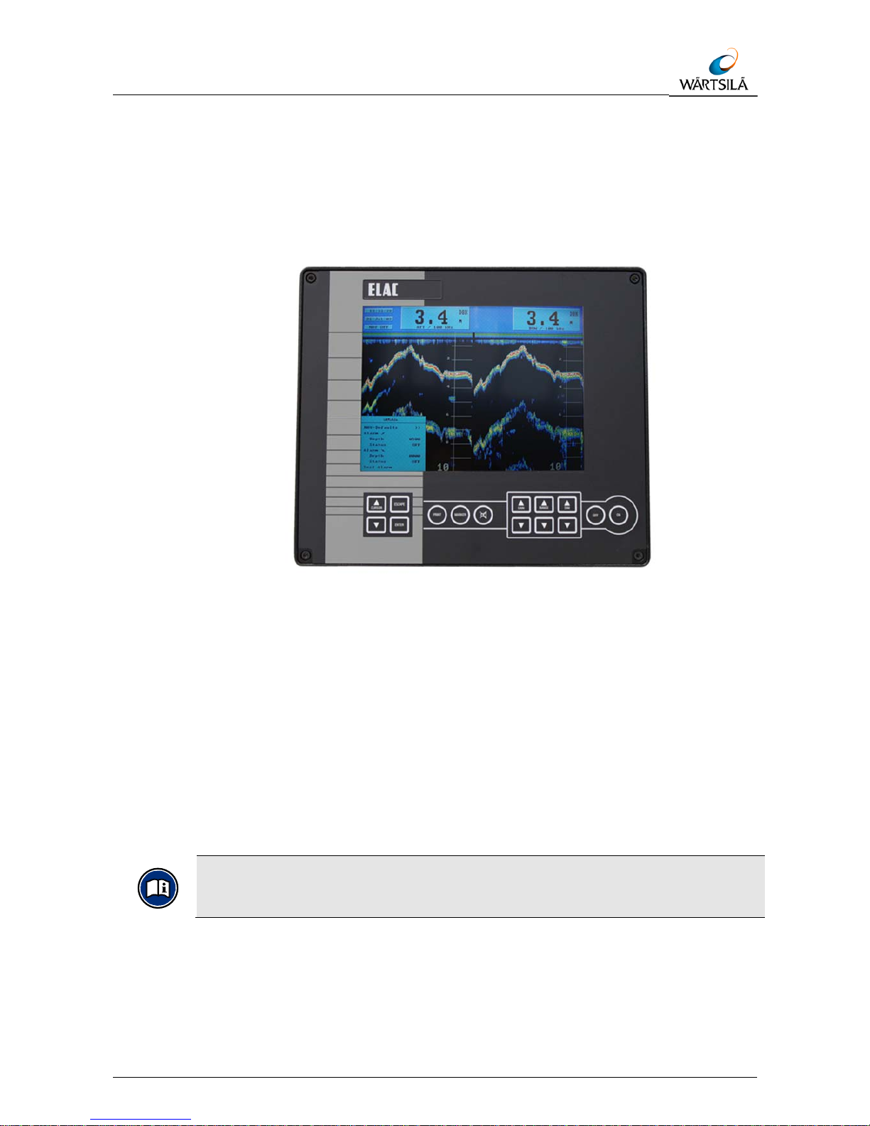
The Navigation Echo Sounder is a compact, processor controlled, state of the art
system.
Indication of the water depth is made on a Liquid Crystal (Colour) Display (LCD) as
depth below the keel (DBK).
Figure 3-1: Display and Control Unit
Logically structured MENUS assist the user when selecting the operating parameters
required. Built to the highest standards, the unit is certified to meet all requirements as
per the IMO Resolution MSC 74/69: Amendments to Resolution A.224, Annex 4.
Wheelmark-tests are certified by the German authority BSH (German Hydrographic
Institute).
3.1.1 Electromagnetic Compatibility
The Navigation Echo Sounder conforms to specifications as per DIN EN 60945
(IEC945+A1) Navigation equipment for Shipping; all editions up to March 1997 and
also to the newest version 4 with measurements up to 2 GHz are valid.
A declaration of conformity, in accordance with European Community
guideline 89/336/EG, is enclosed in the appendix (see chapter 7).
Page 22
Technical Manual LAZ 5100 / ES 5100
TECHNICAL DESCRIPTION
3-2 Technical Manual LAZ 5100 / ES 5100 TH 52 603 8001 EN Rev.: S
3.2 System Configuration
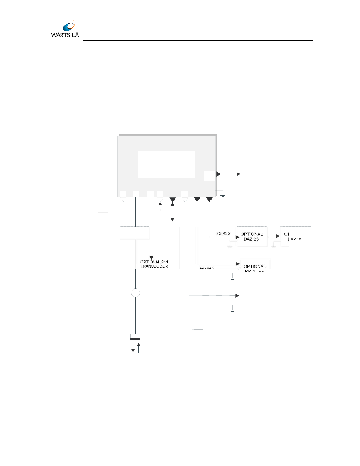
3.2.1 System Overview (with Options)
The basic system configuration is as follows:
1 x Display and Control Unit
1 x Connection Box
1 x Transducer
Figure 3-2: System Block Diagram (with Options)
PRINTER
OPTIONAL
X3
X5X2
X7
X1
X6
X4
X8
X38
RS 422
NMEA
RS 422
CONNECTION BOX
TRANSDUCER
MAINS
MAINS
DAZ 25 DAZ 25
OPTIONAL OPTIONAL
OPTIONAL
OPTIONAL 2nd
TRANSDUCER
Watchkeepers alarm
(Operator’s Fitness Check)
Mute Control, TXD1 for
Voyage Data Recorder
(NMEA, RS 422)
Monitor
Mute Control
Output (Relay
Contact)
RS 422
Navigation Echo
Sounder
LAZ 5100 / ES 5100
SWITCH BOX
(OPTIONAL)
CONNECTION
BOX
Page 23

Technical Manual LAZ 5100 / ES 5100
TECHNICAL DESCRIPTION
TH 52 603 8001 EN Rev.: S Technical Manual LAZ 5100 / ES 5100 3-3
3.2.2 Display and Control Unit
The Display and Control Unit will normally be installed on the bridge, either mounted
in a console or bracket mounted to the deckhead or bulkhead.
It consists of a display area and a keypad which is used to alter system parameters
and settings.
The unit can be a one or two channel version, working with different transducers on
different frequencies, see chapter 3.4 “Technical Data”.
The display area shows the following:
One channel (used with only one transducer)
Water depth
Range scale
Time and Date
Latitude and Longitude (if connected to a navigation system with a standard
NMEA 0183, version 2.0 interface)
Minimum and maximum depth alarm settings (if activated)
A trace of the sea bed
A colour bar representing the signal strength of the echoes
Two channels (used with two transducers)
vertical split display shows on the left half channel 2 information, on the right half
channel 1 information.
Instead of LAT/ LONG a second water depth indication appears.
A built-in ring memory continually stores system data, this allows the user to
recall data to the screen, or print out a hard copy of any or all events occurring
within the last 24 operating hours (if a printer is connected).
3.2.3 Transducer Connection Box
This will usually be installed near the transducer, to allow a defective transducer to be
replaced without having to replace the complete cabling to the Display and Control
Unit. The connection box must be made of metal.
3.2.4 Transducer
The transducer converts electrical energy to sound energy and transmits this towards
the sea bed. Sound energy returning from the sea bed, in the form of echoes, is
converted into electrical energy by the transducer and fed to the Display and Control
Unit for evaluation and presentation.
Page 24
Technical Manual LAZ 5100 / ES 5100
TECHNICAL DESCRIPTION
3-4 Technical Manual LAZ 5100 / ES 5100 TH 52 603 8001 EN Rev.: S
3.3 Optional Equipment
The following optional equipment is available to enhance the system capabilities:
Digital Slave Display(s) (see 3.3.1)
Printer (see 3.3.2)
Connection Box (see 3.3.3)
Transducer(s) (see 3.3.4)
Switch Box (see 3.3.5)
3.3.1 Digital Slave Display(s)
These are used to repeat water depth information at other parts of the ship where
such information is needed. A total of two Digital Slave Displays can be connected
directly to the system.
Echosounding systems and remote indicators which detect and display the
water depth from a single momentary value per transmission pulse, e.g.
digital and pointer displays, can, over a period of time, display false readings.
This is primarily valid in shallow water areas. For this reason, water depths
displayed in this manner must be compared with the graphic presentation at
regular intervals in order to guarantee the ship's safety.
CAUTION!
While crossing steep slopes the echo evaluation might fail.
A steady depth display cannot be guaranteed in this case.
The depth display will show the last evaluated depth value together with a
question mark; longer lasting errors will be indicated by a question mark
without any depth value.
At the digital slave display "----" will be displayed in this case.
3.3.2 Printer
A printer can be connected to give a continuous hard copy of data presented on the
display or to print out a hard copy of events from any time within the previous 24 hour
operating period.
3.3.3 Optional Connection Box
The optional Connection Box (see Figure 3-2) is connected to the Display and Control
Unit and provides the following connections:
a second Digital Slave Display
a blanking pulse output
depth alarm relay contacts (potential free)
Page 25

Technical Manual LAZ 5100 / ES 5100
TECHNICAL DESCRIPTION
TH 52 603 8001 EN Rev.: S Technical Manual LAZ 5100 / ES 5100 3-5
3.3.4 Transducer Options
If the installed version is a dual channel version, the system is capable of
accommodating two transducers without further modification, e.g. one fore and one
aft, one port and one starboard.
Information received from either or both transducer(s) can be called up for display.
3.3.5 Switch Box
If no dual channel version is installed, a switch box (not part of delivery) can be used
for the connection of two transducers of the same type (frequency).
Page 26

Technical Manual LAZ 5100 / ES 5100
TECHNICAL DESCRIPTION
3-6 Technical Manual LAZ 5100 / ES 5100 TH 52 603 8001 EN Rev.: S
3.4 Technical Data
Designation Value
Supply voltage, nominal
95 – 240 V AC, 50 - 60 Hz
10 - 30 V DC (option, via power pack)
Power consumption Approx. 35 W
Operating temperature range -15°C - +55°C
Storage temperature -20°C - +60°C
Housing Cast aluminium
Protection code IP 53
Transducer impedance 50 - 150 Ohms
Pulse length 0.3, 1, 3 ms, (automatically switches to suit range selected)
Measurement ranges
(or the equivalent in feet or
fathoms)
0 - 10, 20, 50, 200, 500, 2000 m
Auto range
depending on the water depth, range scale of 200 m or 50 m will be
selected automatically
Digital Depth Information
150% of measurement range for 0 - 10 m and 0 - 50 m
120% for other ranges
Resolution 1% of range selected
Measuring accuracy ± 1.0% of depth reading
Display Liquid Crystal Display
Display size 192 mm x 144 mm
Pixels 640 (hor.) x 480 (vert.)
Minimum sounding depth 0.5 m or equivalent (Transducer dependent)
Depth corrections:
Transducer-surface
Transducer-keel
up to 9.9 m (up to 29,9 m starting with software version 1.82)
up to 4.9 m
Standard frequencies (kHz) 24, 28, 30, 33, 38, 50, 100, 200 (selectable)
Dual Channel version any combination of the frequencies above
Output power 1000 W Max. dependent upon range selected and transducer installed
Compass Safety Distance:
Magnetic compass
Steering compass
0.5 m
0.3 m
Dimensions (H x W x D) 288 x 336 x 135,6 mm
Weight Approx. 6.1 kg
Operator Fitness Check Alarm
altering parameters of the unit causes an output to a central alarm unit
(potential free relay contact)
Power Fail Alarm
when the power supply voltages decreases by 100 V, a visual and audio
alarm (with mute control) is activated, a potential free output for external
use is available (potential free relay contact)
Tab. 2: Technical data
Page 27

Technical Manual LAZ 5100 / ES 5100
TECHNICAL DESCRIPTION
TH 52 603 8001 EN Rev.: S Technical Manual LAZ 5100 / ES 5100 3-7
3.5 Interfaces
The Navigation Echo Sounder has the following interfaces:
Figure 3-3: Interface Connector Plate
No. Typ Signal Description
X4 D-Sub DE 9 RS 422 NMEA, for Navigation data input, Blanking input
X5 D-Sub DE 9 RS 232 Mute Control Output (relay contact)
X7 D-Sub DB 25
IEEE-1284
Centronics, parallel Printer connection
X8 D-Sub DE 15 RS 422 Digital Slave Display connection and potential free
relay contacts for alarm ACTIVE, relay control for
Operator’s Fitness Check
X6 D-Sub DE 15 RS 422 Power supply for a 2nd Digital Slave Display, and
blanking pulse output, Mute Control input, second
serial output for Voyage Data Recorder, Power Fail
output.
X38 D-Sub DE 15 VGA Interface to an external monitor
Tab. 3: Interfaces
Interface connections are made at the rear of the unit. Figure 3-3 shows which
connector belongs to which interface.
For pin connections see chapter 3.5.3 (Tab. 5: Pin connections).
2nd DAZ
(Blanking,
via Conn. Box)
Mute Control
2nd Serial
Interface RS 422
DAZ 25
(Digital
Slave
Display
RS 422
NMEA 0183)
ALARMRELAY
Operator’s
Fitness Check
Alarm Relay
Power Fail
RS 422
NMEA 0183
( NAV )
Blanking
Input
Printe
r
(Centronics
Parallel)
Monito
r
Mute
Control
output
Page 28

Technical Manual LAZ 5100 / ES 5100
TECHNICAL DESCRIPTION
3-8 Technical Manual LAZ 5100 / ES 5100 TH 52 603 8001 EN Rev.: S
3.5.1 Description of NMEA Interfaces
All serial interfaces described in this chapter conform to EN 61162-1 (2001).
3.5.1.1 NMEA-Interface X4
A navigation system can be connected to this interface so that the ship's co-ordinates
are displayed by the NAVIGATION ECHO SOUNDER.
The system will accept and evaluate data sentences in NMEA 0183, Version 2.30,
GLL and ZDA formats, as follows:
GLL Format:
Example:
ZDA Format:
$--GLL IIII.II,a yyyyy.yy,a hhmmss.ss A hh, , , , * <CR><LF>
Checksum
Status : A =Data Valid
UTC at this position
Longitude, E/W
Latitude, N/S
Talker Identification
$--ZDA hhmmss.ss xx,xx,xxxx xx,xx hh,,,*<CR><LF>
Checksum
Difference between UTC and
GMT
Day,Month,Year
UTC
Ta lker Identification
$GPGLL 5420.549,N 01007.192,E 201533.25 A 0
2
,, ,,*<CR><LF>
Checksum
Data Valid
UTC =20:15:33.25
Longitude=10°07.192’E
Latitude=54°20.549’N
Data are being received from
a Global Positioning System
Page 29

Technical Manual LAZ 5100 / ES 5100
TECHNICAL DESCRIPTION
TH 52 603 8001 EN Rev.: S Technical Manual LAZ 5100 / ES 5100 3-9
Example:
3.5.1.2 NMEA-Interface X8
Interface for START / STOP - SLAVE indicator, potential free alarm relay contacts and
Digital Slave Indicator.
After each sounding the NAVIGATION ECHO SOUNDER transmits depth information
to the Digital Slave Display interface (15 to 60 times per minute, depending upon the
measuring range selected) in NMEA, Version 2.00 format. The DPT (Depth) and DBT
(Depth Below Transducer) sentences are as follows:
DPT (Depth)
Example:
Depth Below Transducer (DBT):
Example:
$ZAZDA 184533.20 20,12,1995 12,15 62, , , * <CR><LF>
Checksum
Difference 12 hrs 15 mins
Date 20th Dec 1995
UTC=18:45:33.20 s
Data are originating from
an atomic clock
$SDDBT x.x,f x.x,M x.x,F hh, , , * <CR><LF
>
Checksum
Depth in fathoms
Depth in metres
Depth in feet
$SDDPT x.x -x.x xx hh, , , ,* <CR><LF>
Checksum
Distance transducer-keel
in metres
Depth in metres
Range Scale
$SDDPT0337.0 -1.
5
, , ,0500,*4D<CR><LF>
Checksum
Transducer=1.5 metres above
the keel
Depth in metres
Range Scale
Page 30

Technical Manual LAZ 5100 / ES 5100
TECHNICAL DESCRIPTION
3-10 Technical Manual LAZ 5100 / ES 5100 TH 52 603 8001 EN Rev.: S
$SDDBT 0012.1,f 0003.7,M 0002.0,F 32,, , *<CR><LF
>
Checksum
Depth = 2 fathoms
Depth = 3.7 metres
Depth = 12.1 feet
Page 31

Technical Manual LAZ 5100 / ES 5100
TECHNICAL DESCRIPTION
TH 52 603 8001 EN Rev.: S Technical Manual LAZ 5100 / ES 5100 3-11
ELA (Manufacture’s Mnemonic Code)
A NMEA proprietary sentence by ELAC is available to allow the transfer of dual
channel depth information, including transducer mounting position.
Character Definition Meaning
k Transducer location
S= Starboard
P= Port
B= Bow
A= Aft
0=not selected
m Selected Depth mode
K=DBK (Depth below Keel)
S=DBS (Depth below Surface)
T=DBT (Depth below Transducer)
r Range scale
q
Quality of digital depth reading
0=no depth information available
1=no depth information available, poor quality
2=depth information available, high reliability
Tab. 4: ELA (Manufacture’s Mnemonic Code)
Example:
Checksum
$PELACSDS,k,x.x,d.d,-t.t,m,g,r*hh<CR><LF>
Range Scale
Depth quality
Selected depth mode
Distande transducer-keel
in metres (TRIM)
Distance transducer-surface
in metres (DRAFT)
Depth in metres
Transducer location
Manufacture´s mnemonic code
P:Propriatary sentence identifier
$PELACSDS,B,0337.0,3.4,-1.5,K,2,0500* 3F<CR><LF>
Checksum
Range Scale
Depth information, high realibility
Depth below keel
TRIM, transducer 1.5 m above keel
DRAFT, transducer 3.4
below surface
Depth = 337.0 m
Depth from Bow transducer
Page 32

Technical Manual LAZ 5100 / ES 5100
TECHNICAL DESCRIPTION
3-12 Technical Manual LAZ 5100 / ES 5100 TH 52 603 8001 EN Rev.: S
To activate the Protocol ELAC see chapter 5.1.4 Initial System Set-Up.
3.5.2 Description of the other Interfaces
3.5.2.1 Interface X5
Mute Control Output (relay contact).
3.5.2.2 Interface X6
This interface provides a power supply and serial data output for a second Digital
Slave Display and a blanking pulse output.
3.5.2.3 Interface X7
This Centronics interface allows a compatible printer to be connected to the system.
Max. length of printer cable 5 m!
3.5.2.4 Interface X38
This is an output to connect a standard monitor to the echo sounder.
Page 33

Technical Manual LAZ 5100 / ES 5100
TECHNICAL DESCRIPTION
TH 52 603 8001 EN Rev.: S Technical Manual LAZ 5100 / ES 5100 3-13
3.5.3 Pin Connections
nc = not connected / * Blanking + :open Collector (Potential free Transistor output), Blanking - :open Emitter / ** Relays :Contact rating : Umax
28 VDC, Imax 1 A, Max. switching Power: 5W / *** Not in use / **** only for internal ELAC Nautik use / OFC: Operator Fitness Check
Input PC – Test **** Output 2 Printer Output 1 Monitor
Mute VDR / DAZ 25 DAZ 25
Pin X 4 X 5 X 6 X 7 X 8 X 38
1 CANL *** BSL
NMEA – Depth – Out /
VDR(-)
Strobe OFC ** Red
2
NMEA – GPS
– In (+)
Test – In
NMEA – Depth – Out /
VDR (+)
Data 0 OFC ** Green
3 n.c. Test – Out NMEA – Depth – Out (+) Data 1 NMEA – Depth – Out (+) Blue
4 Blanking in - Mute – out ** Mute - in b Data 2 n.c. n.c.
5 Blanking in + Ground Mute - in a Data 3
Alarm A **
common contact
Ground
6 CANH *** Mute – out ** Remote – out + Data 4 Start Ground
7
NMEA – GPS
- In (-)
n.c. Remote – in + Data 5 Stop Ground
8 n.c. n.c. NMEA – Depth – Out (-) Data 6 NMEA – Depth – Out (-) Ground
9 n.c. Vcc Blanking out -* Data 7
Alarm B **
open at alarm
n.c.
10 ----- ----- Blanking out +* ACK
Alarm C **
closed at alarm
Ground
11 ----- ----- Aux. Voltage + BUSY Aux. Voltage + n.c.
12 ----- ----- Remote RS Paper End Power fail 1 ** n.c.
13 ----- ----- Remote – out - Select Power Fail 2 ** Hsync
14 ----- ----- Remote – in - n.c. LSE 2+2 Vsync
15 ----- ----- Aux. Voltage - Error Aux. Voltage - n.c.
16 ----- ----- ----- Reset ----- ----17 ----- ----- ----- n.c. ----- ----18 ----- ----- ----- Ground ----- ----19 ----- ----- ----- Ground ----- ----20 ----- ----- ----- Ground ----- ----21 ----- ----- ----- Ground ----- ----22 ----- ----- ----- Ground ----- ----23 ----- ----- ----- Ground ----- ----24 ----- ----- ----- Ground ----- ----25 ----- ----- ----- Ground ----- -----
Tab. 5: Pin connections
Page 34

Page 35

Technical Manual LAZ 5100 / ES 5100
OPERATING INSTRUCTIONS
TH 52 603 8001 EN Rev.: S Technical Manual LAZ 5100 / ES 5100 4-1
4 OPERATING INSTRUCTIONS
CAUTION!
Operating errors possible!
The system must be operated by trained, qualified personnel only!
4.1 Switching the System On/Off
The transducer will be destroyed if operated out of water!
Operate the system (if necessary) only when the transducer is immersed in
water!
Figure 4-1: Display and Control Unit
To switch the System ON, press the far right-hand key marked "ON". The system will
switch ON and recall the parameter settings which were selected when the system
was last switched OFF.
To switch the system OFF, press and hold the second key from the right, marked
"OFF“, the system will switch OFF after about 3 to 5 seconds. This is a built-in safety
feature to prevent accidental switching OFF.
For brief explanation of the control keys see chapter 4.2.
Page 36

Technical Manual LAZ 5100 / ES 5100
OPERATING INSTRUCTIONS
4-2 Technical Manual LAZ 5100 / ES 5100 TH 52 603 8001 EN Rev.: S
4.2 Brief Explanation of Control Keys
CURSOR
GAIN RANGE DIM
ESCAPE
ENTER
PRINT MARKER
ONOFF
Figure 4-2: Keypad
Key Value
CURSOR
The CURSOR keys allow the user to move the cursor within a
MENU and alter parameters. The position of the cursor can easily
be seen, the word, letter or digit marked by the cursor appears
inverse (dark background, light text).
Parameters to be altered must first be "marked" with the cursor.
ESCAPE
The ESCAPE key is used to leave a MENU or to abort parameter
alterations.
ENTER
The ENTER key is used to call up MENUS and confirm
parameter alterations within MENUS.
GAIN
The GAIN keys are used to alter the system gain, known as
amplification, to achieve a clearer presentation in automatic gain
control mode. See chapter 4.4.1.
RANGE
The RANGE keys are used to set the depth range of the system.
DIM
The DIM keys are used to set the display backlighting level to
suit the user.
PRINT
The PRINT key is used when the user wants to make a
simultaneous hard copy of the echogram. This is only possible if
a printer is connected to the system.
MARKER
When the MARKER key is pressed, a vertical dotted line
appears on the screen and moves with the presentation from
right to left. At the same time all relevant information is stored in
the system's 24 hour memory. This memory stores data from the
previous 24 operating hours.
SYMBOL
The key marked with a loudspeaker symbol is used to
acknowledge acoustic depth alarms.
Tab. 6: Control keys
Page 37

Technical Manual LAZ 5100 / ES 5100
OPERATING INSTRUCTIONS
TH 52 603 8001 EN Rev.: S Technical Manual LAZ 5100 / ES 5100 4-3
4.3 Display Area
4.3.1 Single Channel Display
The Display Area is used to present all relevant information. The screen is divided into
two areas. The lower, main area is used to present an echogram of the scenario
beneath the ship. It is provided with a scale and time markings. The range in use is
displayed beside the scale markings, at the bottom right of the screen. The time
markings appear at 3 minute intervals at the bottom edge of the screen.
As explained previously, when MENUS are called up, they will appear at the
bottom left-hand side of this area.
The smaller strip across the top of the screen provides the user with various system
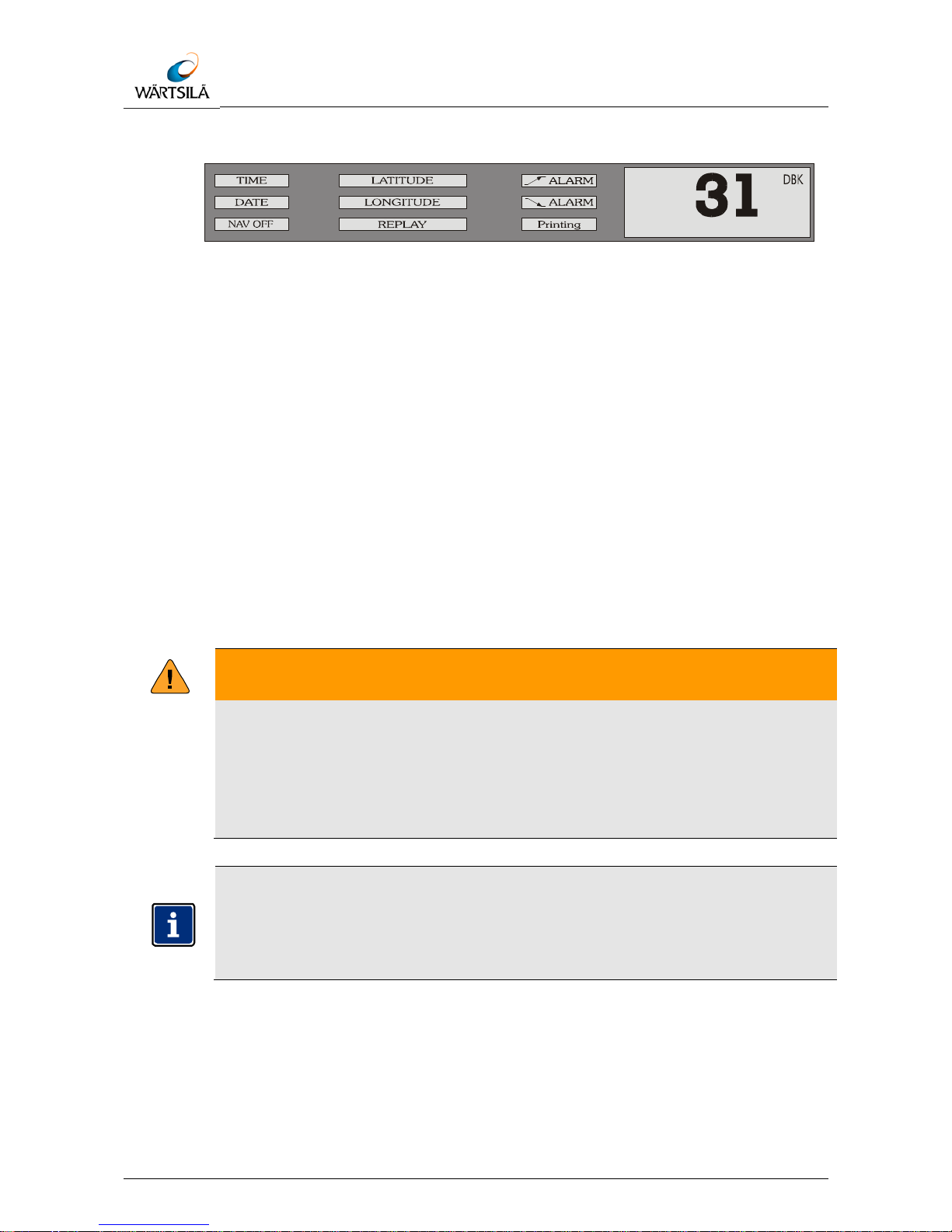
and depth information (see illustration below).
Figure 4-3: Single Channel Display
Explanation of information contained in the illustration above:
Information Explanation
TIME
Shows the actual time
DATE
Shows the actual date
NAV OFF
Flashes to indicate that the Navigation mode is not in use i.e. the user have
selected other units, sound velocity or depth mode. When the user returns to
the Navigation mode, by selecting NAV Defaults, this window will disappear
(see also chapter 4.5.1.1, NAV-Defaults). If the echo sounder is in the dual
channel mode (only if the second channel and a second transducer is fitted),
NAV - OFF is activated without flashing.
LONGITUDE/
LATITUDE
These windows will display the actual Lat. and Lon. (only if the system is
connected to the ship's navigation system).
Printing
This window is usually blank. If the user chooses to make a hard copy of the
echogram, by pressing the printer key (a printer must be connected) the word
"Printing" will appear here.
ALARM
These windows show the depth alarm settings. The upper window shows the
minimum depth alarm, the lower window shows the maximum depth alarm. If
the alarms are not activated, e.g. Status = OFF, the relevant window(s) will
remain blank. If an alarm condition occurs, the relevant window will flash.
REPLAY
When the user chooses to display information stored over the previous 24
operating hours (using the LOG DATA MENU), the word "REPLAY" will appear
here.
Tab. 7: Shown information
mm
Page 38
Technical Manual LAZ 5100 / ES 5100
OPERATING INSTRUCTIONS
4-4 Technical Manual LAZ 5100 / ES 5100 TH 52 603 8001 EN Rev.: S
Figure 4-4: Single Channel Display
The large window at the right-hand side of the information area is used to display the
actual water depth, the measurement mode, units of measurement. The measurement
mode can be either:
Depth Below the Keel = DBK (as shown)
Depth Below the Surface = DBS
Depth Below the Transducer = DBT
The units of measurement can be either:
Meters (m; as shown)
Feet (ft)
Fathoms (ftm)
WARNING!
If no valid bottom depth is available, instead of the depth value a “?” appears.
The reason can be loss of the bottom signal by distortion or other influence
or the bottom depth is out of the selected range.
Therefore in case of the “?” appearance check the selected range and the
analogue bottom trace.
While crossing steep slopes, the echo evaluation might fail. A steady depth
display cannot be guaranteed in this case. The depth display will show the
last evaluated depth value together with a question mark; longer lasting errors
will be indicated by a question mark without any depth value. At the digital
slave display "----" will be displayed in this case.
mm
Page 39

Technical Manual LAZ 5100 / ES 5100
OPERATING INSTRUCTIONS
TH 52 603 8001 EN Rev.: S Technical Manual LAZ 5100 / ES 5100 4-5
4.3.2 Two Channel Display
In the two channel mode, information about location and frequency of the transducer
in use is added.
Figure 4-5: Two Channel Display
If the presentation channel 1/2 is selected, Information of both channels is shown in a
vertical split display.
The indication NAV OFF is activated without flashing to indicate, that the
mode of presentation is non standard. For each transducer the depth location
and frequency is shown.
For transducer location and frequency see chapter 5.1.4 Initial System SetUp.
4.3.2.1 Warning Fields
Three warning fields are shown on the display:
Field Explanation
NAV OFF
NAV OFF flashing indicates that one or more parameters do not
correspond to the navigational mode, i.e. the user has selected other
units, sound velocity or depth mode.
NAV OFF without flashing appears in the 2 channel mode. It indicates
that in this display mode the user has to observe, that for instance
digital slave repeaters are in use.
POWER ERROR
POWER ERROR occurs when the supply voltage of the echo sounder
unit falls below a value of 100 V AC. This is an internal alarm, the
POWER ERROR field flashes and an acoustic alarm (with mute control)
is activated.
Tab. 8: Shown information
40
10
20
20
40
10
20
20
m
m
Page 40

Technical Manual LAZ 5100 / ES 5100
OPERATING INSTRUCTIONS
4-6 Technical Manual LAZ 5100 / ES 5100 TH 52 603 8001 EN Rev.: S
4.4 Altering System Parameters and Settings
When the system is switched OFF, parameters selected are stored in the system's
memory. When the system is switched ON again, these parameters will be retrieved
and used (see NOTE below).
The "DIM" setting is not stored; a pre-set default setting is used when the
system is switched ON. With two channel systems, channel 1 is the default
channel at start-up.
4.4.1 GAIN, RANGE and DIM Settings
GAIN (amplification), RANGE (depth range) and DIM (display area background
lighting and keypad illumination) settings are made by pressing the relevant keys.
There are two keys for each setting, one marked with an arrow pointing upwards and
one marked with an arrow pointing downwards. Pressing these keys as described
below will alter the present setting. The new setting will appear briefly on the display
area directly above the key which was pressed and the effects of a change can be
observed directly on the display area. Pressing the key a second time will alter the
setting by a further unit.
4.4.1.1 GAIN Settings
The unit is fitted with an automatic gain control circuit for the data processing which is
always activated when the unit is switched on. The GAIN setting only influences the
displayed echo information. The GAIN value can be altered between 1 and 10,
whereby 1 is the lowest and 10 the highest gain (amplification) factor.
If the sea bed trace appears too weak, the GAIN level must be increased to give a
clear presentation. If there is a lot of "noise" to be seen on the display area, the GAIN
level must be decreased.
To increase the GAIN level, press the GAIN key . To decrease the GAIN level,
press the GAIN key .
The set value will appear on the display area above the key (between 1 and 10).
Pressing the same key a second time will increase or decrease the value by one
further unit. Repeat the procedure until a satisfactory sea bed trace is achieved.
In some cases it can be useful to work with manual instead of automatic gain. Manual
gain setting is explained in chapter 4.5.2.5.
Page 41

Technical Manual LAZ 5100 / ES 5100
OPERATING INSTRUCTIONS
TH 52 603 8001 EN Rev.: S Technical Manual LAZ 5100 / ES 5100 4-7
4.4.1.2 RANGE Settings
The RANGE can be set to suit the circumstances e.g. if a water depth of 35 m is
indicated, the 50 m range will give a better resolution and accuracy than the 200 m
range.
The range can be altered in the same way as the gain, except that here, pressing the
RANGE key will decrease the range and pressing the RANGE key will
increase the range.
There are 6 ranges to choose from, 10, 20, 50, 200, 500 and 2000 m (or the
equivalent in fathoms or feet). Selecting the unit of measurement is described in
chapter 4.5.2.3.
When increasing the range to more than 2000 m scale, an "A" will appear together with
the 200 m scale. "A" indicates the selection of the automatic mode. When the water
depth decreases to a depth less than 50 m, the range will automatically switch to the
50 m range scale; if the water depth increases, the 200 m range will be selected. By
pressing the range keys in the automatic mode, manual control is activated.
When DBS is used, the ranges 0-10 m; 0-20 m are not available, only 0-50 m.
4.4.1.3 DIM Settings
The display background lighting can be set in 10 steps to suit the ambient light. To
increase the display background lighting, press the DIM key . To decrease the
display background lighting, press the DIM key .
All other parameters and settings are altered within so called MENUS, as
described in chapters 4.4.2 and 4.5.
Page 42

Technical Manual LAZ 5100 / ES 5100
OPERATING INSTRUCTIONS
4-8 Technical Manual LAZ 5100 / ES 5100 TH 52 603 8001 EN Rev.: S
4.4.2 General Information Regarding Menus
The ENTER key is used to call up the various MENUS in sequence.
They appear in the following order:
Press the ENTER key 1x : ALARM MENU
Press the ENTER key 2x : PARAMETER MENU
Press the ENTER key 3x : LOG DATA MENU
Press the ENTER key 4x . SYSTEM SETUP MENU
If the ENTER key is pressed 5x, the ALARM MENU will re-appear.
When a MENU is called up, the title will be highlighted i.e. it will appear in inverse text,
this means light text on a dark background or vice versa, depending on the DIM
setting. During daylight use, the text will be light on a dark background and during
darkness, when the screen is dimmed, the text will be dark on a light background.
When the title line of a MENU is highlighted, it is possible to leave that MENU by
pressing the ESCAPE key 1x, or to change to another MENU by pressing the ENTER
key 1x or more often, until the desired MENU appears.
If parameters or settings have been altered within a MENU, the ESCAPE key may
have to be pressed more than 1x in order to either return to the title line or to leave the
MENU completely. The ESCAPE key can also be used to abort parameter selections.
A detailed example of altering system settings and parameters within a MENU can be
seen in chapter 4.4.3. The user should read this section thoroughly and practice the
alterations described in order to become familiar with the system.
WARNING!
Do not alter parameters within the SERVICE SUB-MENU unless authorised to
do so. See also WARNING given in chapter 4.5.4 "The SYSTEM SET-UP
MENU".
Page 43

Technical Manual LAZ 5100 / ES 5100
OPERATING INSTRUCTIONS
TH 52 603 8001 EN Rev.: S Technical Manual LAZ 5100 / ES 5100 4-9
4.4.3 Altering System Settings/Parameters within a Menu
When a MENU is called up, it will appear at the bottom left-hand side of the display
area. There are 4 main MENUS available. These can be called up by pressing the
ENTER key.
Example:
The user wants to change the MINIMUM DEPTH ALARM from 30 m to 20 m and
activate it (Status = ON) and to change the MAXIMUM DEPTH ALARM to 410 m and
activate it.
Press the ENTER key once to call up the ALARM MENU. The ALARM MENU as
shown below appears at the bottom left-hand side of the display area.
Figure 4-6: Alarm Menu
The word ALARM is marked by the cursor and appears inverse, i.e. dark background,
light text.
In order to alter the MINIMUM DEPTH ALARM setting within this MENU, the value to
be altered must be marked by the cursor. This is done by using the CURSOR keys.
The CURSOR key with the arrow pointing downwards ( ) is used to move the cursor
down and the CURSOR key with the arrow pointing upwards ( ) is used to move the
cursor up. Press the CURSOR key twice to mark the word "Depth".
NAV-Defaults >>
Alarm
Depth 0030
Status OFF
Alarm
Depth 1990
Status OFF
Test Alarm
ALARM
Page 44

Technical Manual LAZ 5100 / ES 5100
OPERATING INSTRUCTIONS
4-10 Technical Manual LAZ 5100 / ES 5100 TH 52 603 8001 EN Rev.: S
The MENU below shows that the cursor has been moved down to mark the word
"Depth" which now appears inverse.
Figure 4-7: Alarm Menu
Now press the ENTER key. The cursor will move from the word "Depth" to the first
digit of the alarm setting, in this case a zero. Press the ENTER key twice more and
the cursor will move to the right (and mark the number 3) as shown in the MENU
below.
Figure 4-8: Alarm Menu
Press the CURSOR key once. The number 3 will change to a 2.
Press the ENTER key to confirm the new setting. The cursor will move one digit to the
right.
NAV-Defaults >>
Alarm
Depth 0030
Status OFF
Alarm
Depth 1990
Status OFF
Test Alarm
ALARM
Depth
NAV-Defaults >>
Alarm
Depth 0030
Status OFF
Alarm
Depth 1990
Status OFF
Test Alarm
ALARM
3
Page 45

Technical Manual LAZ 5100 / ES 5100
OPERATING INSTRUCTIONS
TH 52 603 8001 EN Rev.: S Technical Manual LAZ 5100 / ES 5100 4-11
Press the ENTER key once more and the cursor will move to mark the word "Status"
as shown in the MENU below:
Figure 4-9: Alarm Menu
Press the ENTER key and the cursor will move to the word "OFF". Press a CURSOR
key ( or ) to toggle from OFF to ON. The MENU will appear as below.
Figure 4-10: Alarm Menu
Press the ENTER key to confirm the setting. The cursor will move to the word "Depth"
as shown in the MENU below.
Figure 4-11: Alarm Menu
NAV-Defaults >>
Alarm
Depth 0020
Status OFF
Alarm
Depth 1990
Status OFF
Test Alarm
ALARM
Status
NAV-Defaults >>
Alarm
Depth 0020
Status
Alarm
Depth 1990
Status OFF
Test Alarm
ALARM
O
N
NAV-Defaults >>
Alarm
Depth 0020
Status ON
Alarm
Depth 1990
Status OFF
Test Alarm
ALARM
Depth
Page 46

Technical Manual LAZ 5100 / ES 5100
OPERATING INSTRUCTIONS
4-12 Technical Manual LAZ 5100 / ES 5100 TH 52 603 8001 EN Rev.: S
Press the ENTER key and the cursor will move to the first digit of the alarm setting, in
this case a 1, as shown in the MENU below.
Figure 4-12: Alarm Menu
Change 1 to a 0 by pressing the CURSOR key. Press the ENTER key to confirm.
The cursor will jump to the next digit, a 9.
Press the CURSOR key repeatedly until the desired value is reached, in this case a
6. Press the ENTER key to confirm. The cursor will move to the next digit, again a 9.
Set this to 1 using the CURSOR key. Press the ENTER key to confirm, the cursor
moves to the 0 which need not be altered.
Now that the desired value, 410 m, has been set, press the ENTER key to confirm.
The cursor will move to the word "Status" as shown in the MENU below.
Figure 4-13: Alarm Menu
Press the ENTER key and the cursor will move to the word "OFF".
The MENU will appear as shown overleaf.
NAV-Defaults >>
Alarm
Depth 0020
Status
Alarm
Depth 990
Status OFF
Test Alarm
ALARM
ON
1
NAV-Defaults >>
Alarm
Depth 0020
Status ON
Alarm
Depth 0610
Status OFF
Test Alarm
ALARM
Page 47

Technical Manual LAZ 5100 / ES 5100
OPERATING INSTRUCTIONS
TH 52 603 8001 EN Rev.: S Technical Manual LAZ 5100 / ES 5100 4-13
Figure 4-14: Alarm Menu
Alter the Status to ON as described for the minimum depth alarm. Press the ENTER
key to confirm. The cursor will move to the words "Test Alarm", as shown in the
MENU below.
Figure 4-15: Alarm Menu
A functional test of the audio/visual alarm can now be carried out by pressing the
ENTER key. The audio alarm must sound and the field(s) showing the alarm setting(s)
on the display area must blink.
Now that the settings have been altered and the alarm tested by pressing the ENTER
key, leave the MENU by pressing the ESCAPE key twice.
NAV-Defaults >>
Alarm
Depth 0020
Status ON
Alarm
Depth 0610
Status
Test Alarm
ALARM
O
FF
NAV-Defaults >>
Alarm
Depth 0020
Status ON
Alarm
Depth 0610
Status
ALARM
OFF
Test Alarm
Page 48

Technical Manual LAZ 5100 / ES 5100
OPERATING INSTRUCTIONS
4-14 Technical Manual LAZ 5100 / ES 5100 TH 52 603 8001 EN Rev.: S
4.5 Menu Description
4.5.1 The ALARM Menu
To call up the ALARM MENU, press the ENTER key once.
Figure 4-16: Alarm Menu
This MENU is used to set, select or test the following:
Select NAV-Defaults
Set Minimum Depth Alarm
Set Maximum Depth Alarm
Test the Alarm system
NAV-Defaults
>
>
Alarm
Depth
0020(0....199
9m)
Status
ON(
ON,OFF)
Alarm
Depth
0410(0....199
9m)
Status
ON(
ON,OFF)
Test Alarm
ALARM
Page 49

Technical Manual LAZ 5100 / ES 5100
OPERATING INSTRUCTIONS
TH 52 603 8001 EN Rev.: S Technical Manual LAZ 5100 / ES 5100 4-15
4.5.1.1 NAV-Defaults
NAV (Navigation)-Defaults are basic compulsory settings which must be used when
operating the system for navigational purposes. These are defined by the International
Maritime Organisation (IMO) and state that:
The system must operate with one channel only
The sound velocity must be set to 1500 m/s
The unit of measurement must be metric ( meters)
Water depth must be measured below the keel (DBK)
If the system is being operated in any other mode, e.g. units selected are feet or
fathoms, water depth from the surface is selected etc., the user can return to the NAV
mode by calling up this MENU and selecting NAV-Defaults. A sub menu will appear
in which the user can choose between selecting NAV-Defaults and returning to the
ALARM MENU. The sub menu is shown overleaf.
This function will
set the sounder
to NAV-Defaults !
Continue ? NO (NO, YES)
WARNING!
Figure 4-17: Alarm Menu (Warning)
To set the system back to NAV defaults, call the ALARM MENU and press the
following keys:
CURSOR (1x, to mark NAV-Defaults)
ENTER (1x, to call up SUB-MENU)
CURSOR or (to select YES)
ENTER (to confirm selection and exit SUB-MENU)
ESCAPE (1x, to leave the MENU)
4.5.1.2 Maximum and Minimum Depth Alarms
The user can set the system alarm so that an audio/visual alarm is released if the
water becomes more shallow than a set minimum or deeper than a set maximum.
This depth is always measured from the ship's keel. An Alarm Test facility is available
so that the alarm function can be periodically tested. These settings are done as
described in chapter 4.4.3.
The audio alarm can be muted externally by a connected Mute Control.
Page 50

Technical Manual LAZ 5100 / ES 5100
OPERATING INSTRUCTIONS
4-16 Technical Manual LAZ 5100 / ES 5100 TH 52 603 8001 EN Rev.: S
4.5.2 The PARAMETER Menu
To call up the PARAMETER MENU, press the ENTER key twice.
Channel Select 1 (1, 2, 1/2)
Sound Velocity 1500 (1400....169 9 )
Units m (m, ftm, ft)
Depth Mode DBK (DBK, DBT, DBS)
(Auto, Man)Gain auto
PARAMETER
Figure 4-18: Parameter Menu
The PARAMETER MENU is used to select system parameters which vary from those
laid down by the IMO. The following settings can be made within this MENU:
Channel selection
Sound velocity setting
Selection of measurement units
Depth mode selection
4.5.2.1 Channel Select
The Channel Select function is only operative in dual channel equipment.
When the system is switched on, channel 1 is the default setting. This function is used
to select the channel to be shown on the display area.
Presentation of Channel 1, Channel 2, or both channels is possible. If both channels
are selected, they will appear side by side on the display area, Channel 1 to the right
and Channel 2 to the left.
Call up the PARAMETERS MENU and press the following keys to make a selection:
CURSOR (1x, to mark Channel Select)
ENTER (1x, to mark Channel number)
CURSOR or (to make selection)
ENTER (1x, to confirm selection)
ESCAPE (2x, to leave the MENU)
Page 51

Technical Manual LAZ 5100 / ES 5100
OPERATING INSTRUCTIONS
TH 52 603 8001 EN Rev.: S Technical Manual LAZ 5100 / ES 5100 4-17
4.5.2.2 Sound Velocity
Sound travels at varying speeds in water, depending upon salinity, temperature and
density. The standard NAV (Navigation) default setting for sound velocity is 1500 m/s.
If a sound velocity measuring system is available and the user wants to adjust the
sound velocity of the depth sounder, call up the PARAMETERS MENU and press the
following keys:
CURSOR (2x, to mark Sound Velocity)
ENTER (1x, to mark 2nd digit)
CURSOR or (to alter 2nd digit)
ENTER (1x, to confirm selection and jump to 3rd digit)
CURSOR or (to alter 3rd digit)
ENTER (1x, to confirm selection and jump to 4th digit)
CURSOR or (to alter 4th digit)
ENTER (1x, to confirm selection)
ESCAPE (2x, to leave the MENU)
4.5.2.3 Units
The standard default unit of measurement is meters. . It is, however, possible to
choose either fathoms or feet.
In order to alter the unit of measurement, call up the PARAMETERS MENU and press
the following keys:
CURSOR (3x, to mark the word Units)
ENTER (1x to mark units selected)
CURSOR or (to make selection)
ENTER (1x, to confirm selection)
ESCAPE (2x, to leave the MENU)
Page 52

Technical Manual LAZ 5100 / ES 5100
OPERATING INSTRUCTIONS
4-18 Technical Manual LAZ 5100 / ES 5100 TH 52 603 8001 EN Rev.: S
4.5.2.4 Depth Mode
The standard default depth measurement mode is DBK (depth below the keel). It is
however possible to change this mode to either DBT (depth below the transducer) or
DBS (depth below the surface).
In order to alter the mode of depth measurement, call up the PARAMETERS MENU
and press the following keys:
CURSOR (4x, to mark Depth Mode)
ENTER (1x, to mark the mode selected)
CURSOR or (to make selection)
ENTER (1x, to confirm selection)
ESCAPE (2x, to leave the MENU)
When the NAV-Defaults are selected within the ALARM MENU, the system
returns to the navigation mode, using the default values, i.e.:
Channel Select = 1
Sound Velocity = 1500 (m/s)
Units = m
Depth Mode = DBK
4.5.2.5 Manual Gain Setting
In a noisy environment or if the bottom depth changes very rapidly it is useful to work
with manual gain instead of automatic gain.
The manual mode is selected as follows:
Select second menu (PARAMETER) by pressing ENTER, ENTER
Select in the PARAMETER menu Gain using the cursor, ENTER
With the cursor change Auto to Man., ENTER
With the GAIN keysgain can now be adjusted
With GAIN UP or DOWN gain can be set between 1 (minimum) and 15 (maximum)
Change the gain value until the bottom is clearly indicated on the display. For
differentiation, the gain value selected is shown inversely on the display during the
use of the gain keys:
Indication with Auto:
Indication with Man.:
During switch off the last gain value used is stored. If the unit is switched on
again, Auto mode is selected. If Man. is selected as described, the last gain
value stored will be recalled.
12
9
Page 53

Technical Manual LAZ 5100 / ES 5100
OPERATING INSTRUCTIONS
TH 52 603 8001 EN Rev.: S Technical Manual LAZ 5100 / ES 5100 4-19
4.5.3 The LOG DATA Menu
To call up the LOG DATA MENU, press the ENTER key three times. The MENU as
shown below will appear.
View Display memory contents
Data Transfer > > Transfer d ata to an ext e rnal P C
for ELAC service only
LOG DATA
!
Figure 4-19: Log Data Menu
The LOG DATA MENU is used to gain access to data stored in the system's built-in
24 hour ring memory. This data can be viewed on the display area and printed out in
full or in part (if an external printer is connected).
WARNING!
During this mode, the echo sounder is not in operation and no actual depth
data will be given. ALARM functions will not be in effect. No data will be
stored.
Page 54

Technical Manual LAZ 5100 / ES 5100
OPERATING INSTRUCTIONS
4-20 Technical Manual LAZ 5100 / ES 5100 TH 52 603 8001 EN Rev.: S
4.5.3.1 To View Stored Data
Call up the LOG DATA MENU as described previously. Press the CURSOR key
once to mark the word "VIEW", followed by the ENTER key.
The MENU will disappear from the screen and stored data will appear. A typical
Viewed Data display area is shown below.
10
20
40
Marker Lines
m
Figure 4-20: Log Data Menu
The upper part of the display area contains the following information which is always
related to the first data block on the extreme right of the display area:
Time and date of stored data
NAV Mode ON or OFF (if the NAV mode was ON when data was stored, this
window will not be shown)
Latitude and Longitude (only if the system was connected to an external navigation
system)
The window showing REPLAY indicates that stored data are being viewed
Depth setting of the shallow water alarm (10 m, if this function was selected)
Depth, unit (m) and mode (DBK) of measurement
Depth range (50 m)
the "Page" and "Printing" windows will be explained later
Page 55

Technical Manual LAZ 5100 / ES 5100
OPERATING INSTRUCTIONS
TH 52 603 8001 EN Rev.: S Technical Manual LAZ 5100 / ES 5100 4-21
4.5.3.2 Explanation of Controls for Viewing Stored Data
40
10
20
30
Marker line a
Marker line b
direction A
Reference line for information and
setting print out time period limits
direction B
m
Figure 4-21: Log Data Menu
Controls for Viewing Data
Key Function
CURSOR
CURSOR
ENTER
MARKER
PRINT
ESCAPE
Scrolls forwards in time (direction A)
Scrolls backwards in time (direction B)
Toggles page scroll option (for faster scrolling)
Marks one limit of the time period to be printed out (start
or finish)
Marks the other limit of the time period to be printed out
and simultaneously activates the printer (if connected)
Exit, return to the echo sounding mode
With the exception of the DIM and OFF keys, all keys are inoperative.
Page 56

Technical Manual LAZ 5100 / ES 5100
OPERATING INSTRUCTIONS
4-22 Technical Manual LAZ 5100 / ES 5100 TH 52 603 8001 EN Rev.: S
4.5.3.3 Scrolling through Memory Data
To scroll the display to a certain time in the memory in order to view events that
occurred earlier (relative to time shown in "time" window), press and hold the
CURSOR key until nearing the wanted time (shown in the "time" window).
Finely adjust the wanted time by pressing the CURSOR or key momentarily,
each time a key is pressed, the time will advance by a 5 second period.
If the event to be viewed occurred considerably earlier, scrolling can be accelerated
by using the "Page scroll" option. Press the ENTER key and the word "Page" will
appear in the window beneath the "Depth Alarm" window. When the CURSOR or
keys are now pressed, the display will be shifted by approx. three quarters of a page
backwards or forwards (pressing and holding these keys scrolls continuously).
EXAMPLE:
To view data at the time when "Marker line a" was set, press and hold the CURSOR
key until the marker line is almost at the right-hand side of the display area. Finally
adjust by pressing the CURSOR repeatedly until the marker is at the outer right-
hand side of the display area.
The data will now be presented in the upper part of the display. To move "Marker line
b", press the ENTER key. The word "Page" will appear in the window below the alarm
window showing that the "Page scroll" option is activated. When the CURSOR is
now pressed once, the marker line will move to the right. Press the ENTER key to
return to the "slow scroll" option and finally adjust as previously described for "Marker
line a".
Depth, scale and position information will not be updated during scrolling
(only time and echograms) except when a marker line passes the right-hand
border of the display area.
The following information can be read off the display for any given time during the
previous 24 system operating hours:
Water depth at that time
Units and mode of measurement at that time
Range in use at that time
Time and date when the information was stored
Whether the NAVIGATION mode was in use at that time
Latitude and Longitude when the information was stored (if connected to a
navigation system)
Whether a shallow water alarm was activated at that time
Page 57

Technical Manual LAZ 5100 / ES 5100
OPERATING INSTRUCTIONS
TH 52 603 8001 EN Rev.: S Technical Manual LAZ 5100 / ES 5100 4-23
4.5.3.4 Printing Data from the Memory
In order to make a print-out of all or part of the data stored in the memory, so called
"limit markers" must be set. Only data within these limit markers will be printed.
To set these limit markers and print the data within them, proceed as follows:
Scroll the display area until one limit is reached (the time is shown in the "time
window").
Press the MARKER key (the time of the right hand side of the display appears in a
window below the depth alarm window)
Scroll the display area until the other limit is reached (the time is shown in the "time
window").
Press the PRINT key, the time in the window below the depth alarm window will be
replaced by the word "Wait", followed by the word "Printing" within short.
During printing, the user may scroll further within the memory. The print-out can be
stopped at any point by pressing the PRINT key for a second time.
4.5.3.5 Fault Conditions during Print
When the PRINT key is pressed, a fault condition may occur.
If so, one of the 3 fault conditions shown below will be indicated in the window
beneath the depth alarm window:
PERIOD? : This indicates that the user has set both limit markers to the
same time. The limit markers must be set to different times.
PAPER OUT : The printer has run out of paper
ERROR : The printer is not connected, not switched ON, or otherwise
defective
4.5.3.6 Making a Hard Copy of the Screen Data
In order to make a hard copy of data displayed on the screen, scroll to the desired
position and press the PRINT key. A window will appear containing the word
"Hardcopy". The print-out will be an exact reproduction of the screen at the time the
PRINT key was pressed.
With the exception of the PRINT and ESCAPE push-buttons, all other controls
are disabled during the time it takes to print out a hard copy of the screen.
The PRINT push-button will stop the printing process and the ESCAPE pushbutton will exit the LOG-DATA feature and return the system to echo-
sounding operation.
Page 58

Technical Manual LAZ 5100 / ES 5100
OPERATING INSTRUCTIONS
4-24 Technical Manual LAZ 5100 / ES 5100 TH 52 603 8001 EN Rev.: S
4.5.4 The SYSTEM-SETUP Menu
WARNING!
With the exception of time, date and colour, no other parameters must be
altered unless modifications are made to the system, e.g. altering the
installation depth of the transducer or replacing the transducer with one of a
different frequency. Alteration of such parameters must only be made by an
experienced service technician.
DANGER!
Parameter alterations made by non-qualified persons may lead to incorrect
depth readings which in turn can lead to material damage and to the loss of life
and limb
To call up the SYSTEM SET-UP MENU, press the ENTER key four times. The MENU
as shown below will appear.
Figure 4-22: System Set-Up Menu
The SYSTEM SETUP MENU is used to set the Time and Date and to gain access to
the SERVICE and INTERFACE SUB MENUS to allow the service technician to alter
installation and interface parameters (see above warning).
D
ate 05.05.03
T
ime 12:34
Color Bar
Version
SYSTEM-SETUP
Service >>
Version number and date
Page 59

Technical Manual LAZ 5100 / ES 5100
OPERATING INSTRUCTIONS
TH 52 603 8001 EN Rev.: S Technical Manual LAZ 5100 / ES 5100 4-25
4.5.4.1 Changing the Date and Time
To change the system DATE, call up the SYSTEM SETUP MENU and press the
following keys:
CURSOR (1x, to mark the word Date)
ENTER (1x, to mark the day setting)
CURSOR or (to alter the day setting)
ENTER (1x, to confirm selection and jump to the month setting)
CURSOR or (to alter the month setting)
ENTER (1x, to confirm selection and jump to the year setting)
CURSOR or (to alter the year setting)
ENTER (1x, to confirm selection)
ESCAPE (2x, to leave the MENU)
To change the system TIME, call up the SYSTEM SETUP MENU and press the
following keys:
CURSOR (2x, to mark the word Time)
ENTER (1x, to mark the hour setting)
CURSOR or (to alter the hour setting)
ENTER (to confirm selection and jump to the minutes setting)
CURSOR or (to alter the minutes setting)
ENTER (1x, to confirm selection)
ESCAPE (2x, to leave the MENU)
Page 60

Technical Manual LAZ 5100 / ES 5100
OPERATING INSTRUCTIONS
4-26 Technical Manual LAZ 5100 / ES 5100 TH 52 603 8001 EN Rev.: S
4.5.4.2 Color Bar Menu
Figure 4-23: System Set-Up Menu (Color Bar Menu)
The Color Bar Menu allows user settings according to ambient conditions. Several
combinations of echo indication and the overlay of general information are possible
according to the following table.
Example: CC B>R means
CC: Coloured overlay, Coloured echo trace
B>R: Blue are weak echoes, Red are strong echoes
CODE
Letters 1+2 Overlay Letters 3+4 Echo level Colours
Text Background High Low
CC Black Coloured B>W White Black 8 blue to white on black
GC Grey Dark grey B>W White Black 8 blue to white on black
GG Grey Dark grey B>W White Black 16 grey level on black
GG Grey Dark grey W>B Black White 16 grey level on white
CC Black Coloured B>R Red Black 16 blue to red on black
GC Grey Dark grey B>R Red Black 16 blue to red on black
Installation settings are made within the SERVICE and INTERFACE SUBMENUS described in chapter 5 “INSTALLATION, CARE AND MAINTENANCE”.
Date 05.05.03
Time 12:34
Color Bar
Version
SYSTEM-SETUP
Service >>
Version number and date
Page 61

Technical Manual LAZ 5100 / ES 5100
OPERATING INSTRUCTIONS
TH 52 603 8001 EN Rev.: S Technical Manual LAZ 5100 / ES 5100 4-27
Page 62

Page 63

Technical Manual LAZ 5100 / ES 5100
INSTALLATION, CARE AND MAINTENANCE
TH 52 603 8001 EN Rev.: S Technical Manual LAZ 5100 / ES 5100 5-1
5 INSTALLATION, CARE AND MAINTENANCE
WARNING!
Danger for man and machine
The operational safety of the system will be endangered if work is not carried
out correctly and/or if unauthorised modifications are made!
Repair work must be carried out by suitably qualified, trained and authorised
specialist personnel (see chapter 1.2.2)!
The applicable local safety regulations must be strictly adhered to when
carrying out maintenance or repair work on the system!
5.1 Installation
The display and control unit can be panel-, bulkhead-, deck head- or console
mounted. The system is delivered with mounting brackets as specified by the user.
Install the display and control unit in accordance with the relevant section of the
Installation Drawing Number EZ 52 603 8001 which is enclosed in chapter 6
"DRAWINGS" of this manual.
At the mounting place, no direct sun light should influence the visibility of
the display. For clear display readings a viewing angle of ±50° perpendicular
to the display is recommended.
The echo sounder performance is limited by the acoustic in-water characteristics.
These are mainly influenced by the transducer mounting position, the operating
frequency and the efficiency of electrical-acoustical conversion.
The transducer position must be selected in a way that the radiating surface is
mounted in an area virtually free of turbulence and air bubbles. The sound waves
reflected by any layers of air bubbles or turbulence are so strong, that the sound
cannot pass the layers and thus echo sounding is prevented.
Because of this, the transducers should be mounted within the ship's bow area. In
case of an existing bow thruster, the transducer must be mounted ahead or below the
thruster outlet.
If mounted behind the bow thruster, the performance of the echo sounder will
be degraded by turbulence and air bubbles. Even a total echosounding break
down is possible.
During bow thruster operation, echo sounding is not possible because a wide area
around the thruster´s outlet is saturated with turbulence and air bubbles.
Page 64

Technical Manual LAZ 5100 / ES 5100
INSTALLATION, CARE AND MAINTENANCE
5-2 Technical Manual LAZ 5100 / ES 5100 TH 52 603 8001 EN Rev.: S
On ships equipped with a bulb bow, the transducer must be mounted as far as
possible ahead, because the bulb generates a layer of air bubbles that heavily
reduces the transducer / echo sounder performance.
A transducer mounted in the vicinity of the ship's stern can be operated only while
drifting, at the pier or at very low speed. The reason is that the stern area is generally
disturbed by turbulence and air bubbles, dependent on ship's speed. In addition,
vibrations and engine noise may be a source of disturbances. The sound signal
cannot penetrate this layer, the bottom echo fades away and the digital display shows
the zero echo (1 - 1.5 m) or "?". Therefore only the front transducer must be used
while sailing.
Once the transducer has been installed, the system must be set up to under
consideration of several factors:
These are:
Transducer installation depth beneath the surface.
Transducer installation height relative to the lowest part of the ship's keel.
Blocking depth, a setting to prevent false digital depth readings caused by
resonance of non-ELAC transducers. This setting needs not to be altered from
ZERO if using ELAC transducers.
Frequency of the transducer.
Installation position of the transducer, e.g. BOW, AFT, Pt., Stb, (if two transducers
are installed).
When a transducer is installed, i.e. before the ship is launched, measure the height
difference between the radiating surface of the transducer and the lowest part of the
keel and the distance between the waterline and the radiating surface of the
transducer. These measurements are necessary to compensate the differences when
the system is initially set up. The transducer frequency is shown in the shipping
documents.
Connect the system in accordance with the connection diagram (see chapter 6).
When cabling the system, take special care that all signal lines are screened properly.
The cable from the transducer to the connection box must be laid in a steel pipe.
From the connection box to the echo sounder there are the following choices for a
proper cable laying:
the transducer cable is laid within a steel pipe, that is connected to the ship’s
ground.
a double-screened cable is used as transducer cable, the inner screen is one-side
connected to the echo sounder's ground, the outer screen is connected to the
ship's ground on both sides ( see Figure 5-1).
The transducer cable is laid at least 0,5 m apart from all other cables.
By no means a single-screened cable must be laid together with any other cable.
Page 65

Technical Manual LAZ 5100 / ES 5100
INSTALLATION, CARE AND MAINTENANCE
TH 52 603 8001 EN Rev.: S Technical Manual LAZ 5100 / ES 5100 5-3
5.1.1 Transducer – Cable Connection
Figure 5-1 Instruction for transducer - cable connection
Page 66

Technical Manual LAZ 5100 / ES 5100
INSTALLATION, CARE AND MAINTENANCE
5-4 Technical Manual LAZ 5100 / ES 5100 TH 52 603 8001 EN Rev.: S
5.1.2 Distortion Level Test
After routing and connecting the transducer cable, a distortion level test must be
carried out, to ensure the correct routing and screening of the transducer cables.
Test procedure:
1. Switch on the echo sounder
2. Select 500 m range
3. Select Display Gain 10 (max.)
4. Select Display Mode 1/2 for Dual Channel Unit
5. Select Item Gain, man. in the Parameter Menu
6. Select Gain 15 (max.)
7. Check the recording on the LCD screen. Below the transmitting pulse and echo
signals no or only a light distortion shall appear on the screen.
8. If a strong distortion appears, check and correct transducer cable routing and
screening according to the Installation Instruction.
9. Repeat test procedure until the display is free of distortion.
10. Return to normal mode
Connect peripheral equipment, i.e. external PC, printer, remote display unit etc. in
accordance with the above mentioned connection diagram, referring to Figure 3-2
“System Block Diagram (with Options)” in chapter 3.2.1.
Page 67

Technical Manual LAZ 5100 / ES 5100
INSTALLATION, CARE AND MAINTENANCE
TH 52 603 8001 EN Rev.: S Technical Manual LAZ 5100 / ES 5100 5-5
5.1.3 Transducer Types
The transducers, listed in the table are samples, further types are available and can
be connected to ELAC echo sounders.
Transducer
Type
Frequency Manufacturer
Electrical
Power
Maximum
Cable Length
(2x1.5mm2)
Maximum
Water Depth
LSE 131 30 kHz ELAC Nautik 1000 Watt 600 m 2000 m
LSE 132 30 kHz ELAC Nautik 450 Watt 600 m 1000 m
LSE 297 50 kHz ELAC Nautik 200 Watt 400 m 600 m
LSE 133 50 kHz ELAC Nautik 450 Watt 600 m 1000 m
LSE 328 100 kHz SAM 250 Watt 200 m 250 – 300 m
LSE 329 100 kHz ELAC Nautik 200 Watt 200 m 250 – 300 m
LSE 148 100 kHz ELAC Nautik 450 Watt 200 m 350 – 400 m
LSE 313 200 kHz ELAC Nautik 200 Watt 150 m 250 – 300 m
LSE 135 200 kHz ELAC Nautik 250 Watt 150 m 200 – 250 m
Tab. 9: Transducer type
The typical maximum water-depths are valid for transducer installation with
direct transmitting into the water.
For cable lengths longer than the ones mentioned in the table, the electrical
power of the echo sounder has to be increased according to manufacturer's
release.
If acoustic windows are installed, the performance can decrease drastically, due to the
losses in the passage of the acoustic beam through the fluid between transducer
surface and acoustic window and the acoustic window itself.
The losses are minimal, if the distance between transducer surface and acoustic
window is lambda/2 and the acoustic window is parallel to the transducer surface.
For frequencies higher than 50 kHz, acoustic windows generate high losses of
performance and should be avoided.
Page 68

Technical Manual LAZ 5100 / ES 5100
INSTALLATION, CARE AND MAINTENANCE
5-6 Technical Manual LAZ 5100 / ES 5100 TH 52 603 8001 EN Rev.: S
5.1.4 Initial System Set-Up
After installation of the Navigation Echo Sounder, please follow this procedure for
setting into operation for the first time.
No. Item Result
1. Installation check
1.1 Main supply (X3)
1.2 Transducer (X1, X2) – cable screening, cable laying
1.3 Printer (X7) – max. cable length 5 m
1.4 NMEA – Output (X8) – RS 422
1.5 NMEA – Input (X4) – RS 422
1.6 Start / Stop – Output (X8)
1.7 NMEA – Output (X6) – RS 422
2. Setting into operation
2.1 Disconnect Printer, NMEA - Input and Output
2.2 Only Main Supply and Transducer connected
2.3 Switch the unit “ON”
2.4 Check and make basically settings
- frequency
- sound velocity (1,500 m/s)
- blocking depth (2 - 2.9 m)
- draft, trim
- NMEA - Interface (4.800 baud, 8N1)
- date and time
2.5 Check the function of the unit
- depth recording
- LC - Display
2.6 Check distortion level
- select 500 m range
- select item Manual Gain
- select gain Vmax (15)
- no or a light distortion shall appear on the LCD – screen
- reduce gain, until the screen is free of distortion
- notice gain level
- return to normal mode
2.7 Connect NMEA - Output (if requested)
- check data at receiving unit
2.8 Connect NMEA - Input (if requested)
- check data on LC- Display
2.9 Connect Printer (if available)
- check recording on printer
2.10 Connect Start/Stop - Output (i.e. DAZ 13) (if requested)
3. Sea Trial
3.1 Check the performance of the transducer
- distortion (air bubbles, turbulence) transducer?
- recording free of electrical noise?
- depth indication, analogue and digital
Page 69

Technical Manual LAZ 5100 / ES 5100
INSTALLATION, CARE AND MAINTENANCE
TH 52 603 8001 EN Rev.: S Technical Manual LAZ 5100 / ES 5100 5-7
Once the system has been correctly installed, the initial set-up can be carried out.
Call the SYSTEM SET-UP MENU by pressing the ENTER key four (4) times. When
the SYSTEM SET-UP MENU appears on the display area, press the CURSOR key
three (3) times so that the word Service is highlighted as shown below.
Figure 5-2 System Set-Up Menu
Press the ENTER key and the WARNING shown below will appear.
Changing parameters
in the following
menus should only
be done by qualified
persons
Continue ? NO NO/YES, select YES for SERVICE menu
WARNING!
Figure 5-3 System Set-Up Menu (Warning)
WARNING!
Only qualified service technicians are allowed to alter these system settings.
If you are not authorised to alter these settings, DO NOT continue. Press
either the ENTER or ESCAPE key to return to the SYSTEM SET-UP menu.
UNAUTHORISED alteration of these settings can endanger the safety of the
ship and lead to loss of life and limb.
If not authorised to make alterations, press the ESCAPE or ENTER key to
return to the SYSTEM SET-UP menu.
Date 05.05.03
Time 12:34
Color Bar
Version
SYSTEM-SETUP
Service >>
Version number and date
Page 70

Technical Manual LAZ 5100 / ES 5100
INSTALLATION, CARE AND MAINTENANCE
5-8 Technical Manual LAZ 5100 / ES 5100 TH 52 603 8001 EN Rev.: S
Access to the SERVICE MENU is gained by pressing any CURSOR key. The word
NO will change to YES. Press the ENTER key and the SERVICE MENU, shown
below, will appear.
Figure 5-4 Service Menu
The SERVICE MENU allows the service technician to access the following subMENUS:
Channel 1 : allows selection of Draft, Trim, Blocking Depth, Frequency and
Location for the Channel 1 transducer.
Channel 2 : allows selection of Draft, Trim, Blocking Depth, Frequency and
Location for the Channel 2 transducer, if fitted. If no second channel is fitted, this
MENU is not available
Interfaces : allows selection of parameters for data transfer.
Display 15 min : altering the selection of the recording display time.
In order to set or alter the parameters for Channel 1, call up the CHANNEL 1 MENU,
as follows:
Call up the SERVICE MENU as previously described
CURSOR (1x, to mark Channel 1)
ENTER (1x, to call up the Channel 1 parameters MENU as seen below)
Figure 5-5 Channel 1 Menu
Channel 1 >> To call up Channel 1 parameter MENU
Channel 2 >> To call up Channel 2 parameter MENU
Interfaces >> To call up interface parameter MENU
SERVICE
Display 15 min ON ON - OFF
Channel 1 >> To call up Channel 1 parameter MENU
Channel 2 >> To call up Channel 2 parameter MENU
Interfaces >> To call up interface parameter MENU
SERVICE
Display 15 min ON ON - OFF
Channel 1 >> To call up Channel 1 parameter MENU
Channel 2 >> To call up Channel 2 parameter MENU
Interfaces >> To call up interface parameter MENU
SERVICE
Display 15 min ON ON - OFF
Power Adjust Norm Adjust Norm
Norm +1dB, +2dB, +3dB, +4dB, +5dB
-2dB, -1dB
Draft 0.0 (0.0..29.9 m)
Trim 0.0 (0.0...4.9 m)
Blocking Depth 0.0 (0.0...2.9 m)
CHANNEL 1
Frequency 50 (24, 28, 33, 38, 50, 100, 200 kHz)
Location BOW (BOW, AFT, Stb., Pt.)
Page 71

Technical Manual LAZ 5100 / ES 5100
INSTALLATION, CARE AND MAINTENANCE
TH 52 603 8001 EN Rev.: S Technical Manual LAZ 5100 / ES 5100 5-9
The CHANNEL 1 MENU allows the service technician to set the following parameters:
Draft: the transducer installation depth is entered here, i.e. the depth
of the transducer below the waterline, e.g. 5.6 m. This compensation allows
accurate surface to sea bed measurements.
Trim: the distance between the transducer and the lowest part of the keel is
entered here, e.g. 0.3 m. This compensation allows accurate keel to sea bed
measurements.
Blocking depth: this setting prevents false digital depth readings caused by the
effects of resonance of non-ELAC transducers. If the water depth is less than the
depth set here, the digital display will show a „?“ but the analogue depth reading
will be displayed correctly.
Frequency: the transducer working frequency is entered here, e.g. 50 kHz.
Location: the position where the transducer is installed is entered here, e.g. BOW.
This parameter is not available for single channel systems!
To alter the Draft setting, press the following keys:
Call up the CHANNEL 1 SUB MENU as described previously
CURSOR (1x, to mark the word Draft)
ENTER (1x, to mark the 1st digit)
CURSOR or (to alter the metre (1st digit) setting)
ENTER (1x, to confirm selection and jump to 2nd digit)
CURSOR or (to alter the 1/10th of a metre (2nd digit) setting)
ENTER (1x, to confirm selection)
ESCAPE (2x, to leave the MENU)
To alter the Trim setting, press the following keys:
Call up the CHANNEL 1 SUB MENU as described previously
CURSOR (2x, to mark the word Trim)
ENTER (1x, to mark the 1st digit)
CURSOR or (to alter the metre (1st digit) setting)
ENTER (1x, to confirm selection and jump to 2nd digit)
CURSOR or (to alter the 1/10th of a metre (2nd digit) setting)
ENTER (1x, to confirm selection)
ESCAPE (2x, to leave the MENU)
Page 72

Technical Manual LAZ 5100 / ES 5100
INSTALLATION, CARE AND MAINTENANCE
5-10 Technical Manual LAZ 5100 / ES 5100 TH 52 603 8001 EN Rev.: S
To alter the Blocking Depth setting, press the following keys:
Call up the CHANNEL 1 SUB MENU as described previously
CURSOR (3x, to mark the word Blocking Depth)
ENTER (1x, to mark the 1st digit)
CURSOR or (to alter the metre (1st digit) setting)
ENTER (1x, to confirm selection and jump to 2nd digit)
CURSOR or (to alter the 1/10th of a metre (2nd digit) setting)
ENTER (1x, to confirm selection)
ESCAPE (2x, to leave the MENU)
To alter the Frequency setting, press the following keys:
Call up the CHANNEL 1 SUB MENU as described previously
CURSOR (3x, to mark the word Frequency )
ENTER (1x, to mark the frequency selected e.g. 200)
CURSOR or (to alter the setting)
ENTER (1x, to confirm selection)
ESCAPE (2x, to leave the MENU)
The new setting can only be activated by re-starting the system (i.e. switch
the system OFF and then ON again).
To alter the Location setting, press the following keys:
Call up the CHANNEL 1 SUB MENU as described previously
CURSOR (5x, to mark the word Location )
ENTER (1x, to mark the location selected e.g. BOW)
CURSOR or (to alter the setting)
ENTER (1x, to confirm selection)
ESCAPE (2x, to leave the MENU)
Page 73
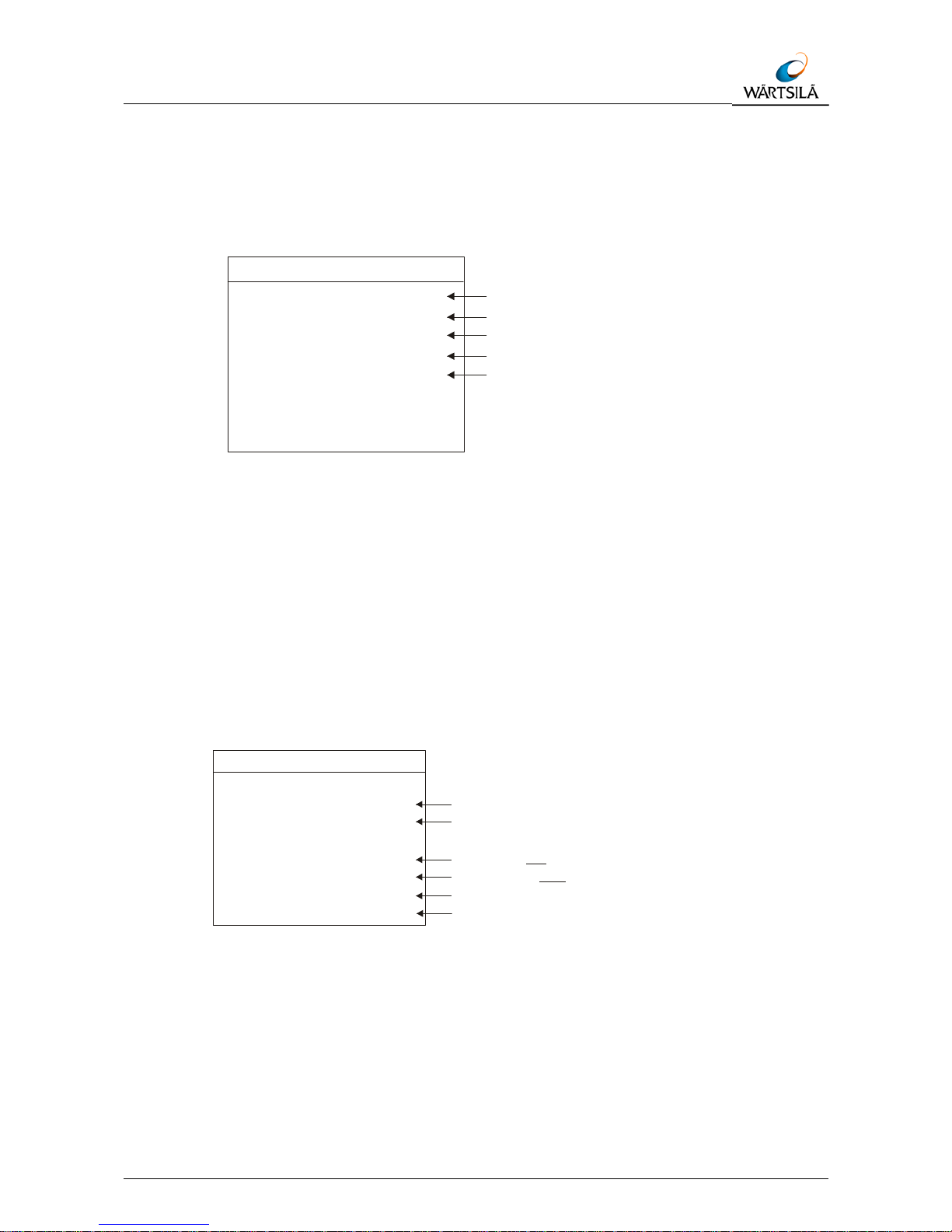
Technical Manual LAZ 5100 / ES 5100
INSTALLATION, CARE AND MAINTENANCE
TH 52 603 8001 EN Rev.: S Technical Manual LAZ 5100 / ES 5100 5-11
In order to set or alter the parameters for Channel 2, call up the CHANNEL 2 MENU,
as follows:
Call up the SERVICE MENU as previously described
CURSOR (2x, to mark Channel 2)
ENTER (1x, to call up the Channel 1 parameters MENU as shown below)
Figure 5-6 Channel 2 Menu
Proceed from here in exactly the same way as described for Channel 1.
To call up the INTERFACE MENU proceed as follows:
Call up the SERVICE MENU as described previously
CURSOR (3x, to mark the word Interfaces)
ENTER (1x, to call up the INTERFACES SUB-MENU)
The INTERFACE MENU shown below will appear.
External PC
Mode 8N1 (7E1, 7E2, 8N1, 8E1, 8N2, 8E2)
Baud 19200 (1200, 2400, 4800, 9600, 19200, 38400 Baud)
NMEA/DAZ 25
Mode 8N1 (7E1, 7E2, , 8 E1, 8N2, 8E 2)8N1
Baud 4800 (1200, 2400, , 9600, 19200, 38400 Baud)4800
Rep. rate SLOW (SLOW, FAST)
INTERFACES
Protocol DPT/DBT (DPT/DBT, ELAC)
Figure 5-7: Interface Menu
This menu allows the service technician to adjust the interfaces to fit to other
peripheral equipment, e.g. a personal computer or digital slave indicators.
Draft 0.0 (0.0..29.9 m)
Trim 0.0 (0.0...4.9 m)
Blocking Depth 0.0 (0.0...2.9 m)
CHANNEL 1
Frequency 50 (24, 28, 33, 38, 50, 100, 200 kHz)
Location BOW (BOW, AFT, Stb., Pt.)
Page 74

Technical Manual LAZ 5100 / ES 5100
INSTALLATION, CARE AND MAINTENANCE
5-12 Technical Manual LAZ 5100 / ES 5100 TH 52 603 8001 EN Rev.: S
To alter the External PC Mode, press the following keys:
Call up the INTERFACES SUB-MENU as described previously
CURSOR (1x, to mark the word Mode)
ENTER (1x, to mark the selected mode)
CURSOR or (to alter the mode)
ENTER (1x, to confirm selection)
ESCAPE (2x, to leave the MENU)
To alter the External PC Baud rate, press the following keys:
Call up the INTERFACES SUB-MENU as described previously
CURSOR (2x, to mark the word Baud)
ENTER (1x, to mark the selected Baud rate)
CURSOR or (to alter the Baud rate)
ENTER (1x, to confirm selection)
ESCAPE (2x, to leave the MENU)
To alter the NMEA/DAZ 25 Mode, press the following keys:
WARNING!
The NMEA/DAZ 25 interface Mode and Baud rate are defined by the National
Marine Electronics Association. If these are altered, the interface will no
longer correspond to this NMEA standard.
Call up the INTERFACES SUB-MENU as described previously
CURSOR (3x, to mark the word Mode)
ENTER (1x, to mark the selected mode)
CURSOR or (1x, to alter the mode)
ENTER (1x, to confirm selection)
ESCAPE (2x, to leave the MENU)
To alter the NMEA/DAZ 25 Baud rate, press the following keys:
Call up the INTERFACES SUB-MENU as described previously
CURSOR (5x, to mark the word Baud)
ENTER (1x, to mark the selected Baud rate)
CURSOR or (to alter the Baud rate)
ENTER (1x, to confirm selection)
ESCAPE (2x, to leave the MENU)
Page 75

Technical Manual LAZ 5100 / ES 5100
INSTALLATION, CARE AND MAINTENANCE
TH 52 603 8001 EN Rev.: S Technical Manual LAZ 5100 / ES 5100 5-13
To alter the Protocol, press the following keys:
Call up the INTERFACES SUB-MENU as described previously
CURSOR (6x, to mark the word Protocol)
ENTER (1x, to mark the selected Protocol)
CURSOR or (to alter the Protocol)
ENTER (1x, to confirm selection)
ESCAPE (2x, to leave the MENU)
Note, that the Protocol ELAC is only applicable for dual channel units, see
also chapter 0 Description of Interfaces.
To alter the recording display time on the LCD – Screen, press the following keys
Call up the Display 15 min Sub Menu as described previously
Enter (1x), to mark “ON” or “OFF”
Cursor to alter the setting
Enter (1x), to confirm the selection
Escape(2x), to leave the Menu
Once the initial system settings have been made they need only be altered if for
example a second transducer is added or if the original transducer is replaced with
one of a different frequency.
If a second transducer is added at a later date, parameters must be entered in the
channel 2 sub-menu. The parameters for channel 1 must not be altered.
(See installation instruction UN 52 590 4001 for the integration of the second
channel).
If the original transducer is replaced and the replacement is fitted at a different
location, the parameters must be altered accordingly.
5.1.5 Power Adjust
This adjust feature allows the authorised service person to alter the transmitting power
according to cable length on board.
Page 76

Technical Manual LAZ 5100 / ES 5100
INSTALLATION, CARE AND MAINTENANCE
5-14 Technical Manual LAZ 5100 / ES 5100 TH 52 603 8001 EN Rev.: S
5.2 Care and Maintenance
The Navigation Echo Sounder is largely maintenance free.
The transducer(s) should be cleaned whenever an opportunity arises, e.g. when the
ship is in dock. The transducer(s) can be cleaned with a plastic scraper or scrubbing
brush, see note below.
Never use metal scrapers or wire brushes to clean the transducer(s). Never
paint the radiating surface of the transducer(s).
The housing of the control and display unit can be cleaned using a non-abrasive
household cleaning agent. Use window/glass cleaning fluid to clean the display area
screen.
Do not apply unnecessary pressure to the screen when cleaning.
If the systems cables are exposed, i.e. are not run in ducts or tubes, check them at
monthly intervals for insulation damage.
If the system is defective and requires repair, onboard service is normally not possible
because of the high density electronics.
For support and ordering of spares contact the address below stating part(s) required
and identification number(s).
Wärtsilä ELAC Nautik GmbH
Manufacturer code: D1876
Neufeldtstraße 10
24118 Kiel
Germany
T
: ++49 (0)431 883-388
v
: ++49 (0)431 883-366
@
: elac.support@wartsila.com
Page 77

Technical Manual LAZ 5100 / ES 5100
APPLICABLE DOCUMENTS
TH 52 603 8001 EN Rev.: S Technical Manual LAZ 5100 / ES 5100 6-1
6 APPLICABLE DOCUMENTS
Designation ELAC Document No. Comment
Dimensional drawing
Echo Sounder LAZ 5100
MB 52 603 8001
Installation drawing
Echo Sounder LAZ 5100
EZ 52 603 8001
Circuit diagram SP 52 603 8001
Connection Diagram VE 44 395 8001
Cable Joining List KA 44 395 8001
EC Type Examination
(Module B) Certificate
for LAZ 5100 latest version
EC Type Examination
(Module B) Certificate
for ES 5100 latest version
EC Certificate of
Conformity Quality System
(Module D)
latest version
EC Declaration of
Conformity
for LAZ 5100 latest version
EC Declaration of
Conformity
for ES 5100 latest version
Tab. 10: Drawings
Page 78

Technical Manual LAZ 5100 / ES 5100
Applicable DOCUMENTS
6-2 Technical Manual LAZ 5100 / ES 5100 TH 52 603 8001 EN Rev.: S
Page 79

Technical Manual LAZ 5100 / ES 5100
APPENDIX
TH 52 603 8001 EN Rev.: S Technical Manual LAZ 5100 / ES 5100 7-1
7 APPENDIX
7.1 Installation – Report
Installation – Report
Schiffsname
Ship’s name _________________________________________________
Installationsfirma
Installation Company _________________________________________________
Installationsdatum
Date of Installation ______________________________
LAZ 5100 ES 5100
Werk-Nr. (S/N) 1-Kanal – Gerät 2-Kanal – Gerät
Serial Number 1-channel unit 2-channel unit
Wandlertyp
Transducer Type S/N
Digitale Tochteranzeige
Digital Display Unit DAZ 25
S/N S/N
Einstellungen
Settings
LAZ 5100 / ES 5100 Kanal 1
Channel 1
Kanal 2
Channel 2
Frequenz / Frequency
Blocking Depth
Draft
Trim
Location
NMEA - Interface
Baud rate
Mode
Repetition Rate
Protocol
Bitte eine Kopie des Installationsreports an Wärtsilä ELAC Nautik Service Centre schicken.
Please forward a copy of the Installation Report to Wärtsilä ELAC Nautik Service Centre.
Fax + 49 431 883 366
 Loading...