

WÄRTSILÄ 50DF Product Manual
WÄRTSILÄ 50DF
PRODUCT GUIDE

© Copyright by WÄRTSILÄ FINLAND Oy
All rights reserved. No part of this booklet may be reproduced or copied in any form or by any means (electronic,
mechanical, graphic, photocopying, recording, taping or other information retrieval systems) without the prior written
permission of the copyright owner.
THIS PUBLICATION IS DESIGNED TO PROVIDE AN ACCURATE AND AUTHORITATIVE INFORMATION WITH
REGARD TO THE SUBJECT-MATTER COVERED AS WAS AVAILABLE AT THE TIME OF PRINTING. HOWEVER,THE
PUBLICATION DEALS WITH COMPLICATED TECHNICAL MATTERS SUITED ONLY FOR SPECIALISTS IN THE
AREA, AND THE DESIGN OF THE SUBJECT-PRODUCTS IS SUBJECT TO REGULAR IMPROVEMENTS,
MODIFICATIONS AND CHANGES. CONSEQUENTLY, THE PUBLISHER AND COPYRIGHT OWNER OF THIS
PUBLICATION CAN NOT ACCEPT ANY RESPONSIBILITY OR LIABILITY FOR ANY EVENTUAL ERRORS OR
OMISSIONS IN THIS BOOKLET OR FOR DISCREPANCIES ARISING FROM THE FEATURES OF ANY ACTUAL ITEM
IN THE RESPECTIVE PRODUCT BEING DIFFERENT FROM THOSE SHOWN IN THIS PUBLICATION. THE PUBLISHER
AND COPYRIGHT OWNER SHALL UNDER NO CIRCUMSTANCES BE HELD LIABLE FOR ANY FINANCIAL
CONSEQUENTIAL DAMAGES OR OTHER LOSS, OR ANY OTHER DAMAGE OR INJURY, SUFFERED BY ANY
PARTY MAKING USE OF THIS PUBLICATION OR THE INFORMATION CONTAINED HEREIN.

Introduction
This Product Guide provides data and system proposals for the early design phase of marine
engine installations. For contracted projects specific instructions for planning the installation
are always delivered. Any data and information herein is subject to revision without notice.
This 2/2016 issue replaces all previous issues of the Wärtsilä 50DF Project Guides.
UpdatesPublishedIssue
Technical data updated09.09.20162/2016
Fuel sharing added. Other minor updates30.06.20161/2016
Chapter Technical data and numerous updates throughout the project guide13.06.20141/2014
Minor updates throughout the product guide03.12.20121/2012
Wärtsilä, Marine Solutions
Vaasa, September 2016
Wärtsilä 50DF Product Guide - a16 - 9 September 2016 iii
IntroductionWärtsilä 50DF Product Guide

Table of contents
1-11. Main Data and Outputs .......................................................................................................................
1-11.1 Maximum continuous output .......................................................................................................
1-21.2 Output limitations in gas mode ....................................................................................................
1-41.3 Reference conditions ...................................................................................................................
1-41.4 Operation in inclined position ......................................................................................................
1-51.5 Dimensions and weights .............................................................................................................
2-12. Operating Ranges ................................................................................................................................
2-12.1 Engine operating range ...............................................................................................................
2-22.2 Loading capacity .........................................................................................................................
2-62.3 Operation at low load and idling ..................................................................................................
2-62.4 Low air temperature ....................................................................................................................
3-13. Technical Data ......................................................................................................................................
3-13.1 Introduction ..................................................................................................................................
3-23.2 Wärtsilä 6L50DF ..........................................................................................................................
3-53.3 Wärtsilä 8L50DF ..........................................................................................................................
3-83.4 Wärtsilä 9L50DF ..........................................................................................................................
3-113.5 Wärtsilä 12V50DF ........................................................................................................................
3-143.6 Wärtsilä 16V50DF ........................................................................................................................
3-173.7 Wärtsilä 18V50DF ........................................................................................................................
4-14. Description of the Engine ....................................................................................................................
4-14.1 Definitions ....................................................................................................................................
4-14.2 Main components and systems ..................................................................................................
4-74.3 Cross section of the engine .........................................................................................................
4-94.4 Free end cover .............................................................................................................................
4-104.5 Overhaul intervals and expected life times ..................................................................................
4-104.6 Engine storage .............................................................................................................................
5-15. Piping Design, Treatment and Installation .........................................................................................
5-15.1 Pipe dimensions ..........................................................................................................................
5-25.2 Trace heating ...............................................................................................................................
5-25.3 Pressure class ..............................................................................................................................
5-35.4 Pipe class ....................................................................................................................................
5-45.5 Insulation .....................................................................................................................................
5-45.6 Local gauges ...............................................................................................................................
5-45.7 Cleaning procedures ...................................................................................................................
5-55.8 Flexible pipe connections ............................................................................................................
5-65.9 Clamping of pipes ........................................................................................................................
6-16. Fuel System ..........................................................................................................................................
6-16.1 Acceptable fuel characteristics ...................................................................................................
6-76.2 Operating principles ....................................................................................................................
6-86.3 Fuel gas system ...........................................................................................................................
6-206.4 Fuel oil system .............................................................................................................................
7-17. Lubricating Oil System ........................................................................................................................
7-17.1 Lubricating oil requirements ........................................................................................................
7-37.2 Internal lubricating oil system ......................................................................................................
7-67.3 External lubricating oil system .....................................................................................................
7-147.4 Crankcase ventilation system ......................................................................................................
7-167.5 Flushing instructions ....................................................................................................................
iv Wärtsilä 50DF Product Guide - a16 - 9 September 2016
Wärtsilä 50DF Product GuideTable of contents

8-18. Compressed Air System ......................................................................................................................
8-18.1 Instrument air quality ...................................................................................................................
8-18.2 Internal compressed air system ..................................................................................................
8-48.3 External compressed air system .................................................................................................
9-19. Cooling Water System .........................................................................................................................
9-19.1 Water quality ...............................................................................................................................
9-29.2 Internal cooling water system ......................................................................................................
9-69.3 External cooling water system ....................................................................................................
10-110. Combustion Air System .......................................................................................................................
10-110.1 Engine room ventilation ...............................................................................................................
10-210.2 Combustion air system design ....................................................................................................
11-111. Exhaust Gas System ............................................................................................................................
11-111.1 Internal exhaust gas system ........................................................................................................
11-311.2 Exhaust gas outlet .......................................................................................................................
11-511.3 External exhaust gas system .......................................................................................................
12-112. Turbocharger Cleaning ........................................................................................................................
12-112.1 Napier turbochargers ...................................................................................................................
12-212.2 ABB turbochargers ......................................................................................................................
12-512.3 Turbocharger cleaning system ....................................................................................................
12-612.4 Wärtsilä control unit for four engines, UNIC C2 & C3 ................................................................
13-113. Exhaust Emissions ...............................................................................................................................
13-113.1 Dual fuel engine exhaust components ........................................................................................
13-113.2 Marine exhaust emissions legislation ..........................................................................................
13-513.3 Methods to reduce exhaust emissions ........................................................................................
14-114. Automation System .............................................................................................................................
14-114.1 UNIC C3 .......................................................................................................................................
14-714.2 Functions ....................................................................................................................................
14-1214.3 Alarm and monitoring signals ......................................................................................................
14-1314.4 Electrical consumers ...................................................................................................................
15-115. Foundation ............................................................................................................................................
15-115.1 Steel structure design ..................................................................................................................
15-115.2 Engine mounting ..........................................................................................................................
15-1415.3 Flexible pipe connections ............................................................................................................
16-116. Vibration and Noise ..............................................................................................................................
16-116.1 External forces and couples ........................................................................................................
16-216.2 Torque variations .........................................................................................................................
16-216.3 Mass moment of inertia ...............................................................................................................
16-316.4 Structure borne noise ..................................................................................................................
16-416.5 Air borne noise .............................................................................................................................
16-516.6 Exhaust noise ..............................................................................................................................
17-117. Power Transmission ............................................................................................................................
17-117.1 Flexible coupling ..........................................................................................................................
17-117.2 Torque flange ...............................................................................................................................
17-117.3 Clutch ..........................................................................................................................................
17-117.4 Shaft locking device ....................................................................................................................
17-217.5 Input data for torsional vibration calculations .............................................................................
17-317.6 Turning gear .................................................................................................................................
Wärtsilä 50DF Product Guide - a16 - 9 September 2016 v
Table of contentsWärtsilä 50DF Product Guide

18-118. Engine Room Layout ...........................................................................................................................
18-118.1 Crankshaft distances ...................................................................................................................
18-218.2 Space requirements for maintenance .........................................................................................
18-418.3 Transportation and storage of spare parts and tools ..................................................................
18-418.4 Required deck area for service work ...........................................................................................
19-119. Transport Dimensions and Weights ...................................................................................................
19-119.1 Lifting of engines .........................................................................................................................
19-519.2 Engine components .....................................................................................................................
20-120. Product Guide Attachments ...............................................................................................................
21-121. ANNEX ...................................................................................................................................................
21-121.1 Unit conversion tables .................................................................................................................
21-221.2 Collection of drawing symbols used in drawings ........................................................................
vi Wärtsilä 50DF Product Guide - a16 - 9 September 2016
Wärtsilä 50DF Product GuideTable of contents
1. Main Data and Outputs
The Wärtsilä 50DF is a 4-stroke, non-reversible, turbocharged and inter-cooled dual fuel engine
with direct injection of liquid fuel and indirect injection of gas fuel. The engine can be operated
in gas mode or in diesel mode.
500 mmCylinder bore ........................
580 mmStroke ...................................
113.9 l/cylPiston displacement .............
2 inlet valves and 2 exhaust valvesNumber of valves .................
6, 8 and 9 in-line; 12, 16 and 18 in V-formCylinder configuration ..........
45°V-angle .................................
clockwiseDirection of rotation ..............
500, 514 rpmSpeed ...................................
9.7, 9.9 m/sMean piston speed ...............
1.1 Maximum continuous output
Table 1-1 Rating table for Wärtsilä 50DF
Diesel electric applicationsMain engines 514
rpm
Cylinder
configuration
514 rpm500 rpm
BHPkWBHPkWEngine [kW]
79505850775057005850W 6L50DF
1060078001034076007800W 8L50DF
1193087751163085508775W 9L50DF
1591011700155001140011700W 12V50DF
2121015600206701520015600W 16V50DF
23860175502326017100N/AW 18V50DF
Nominal speed 514 rpm is recommended for mechanical propulsion engines.
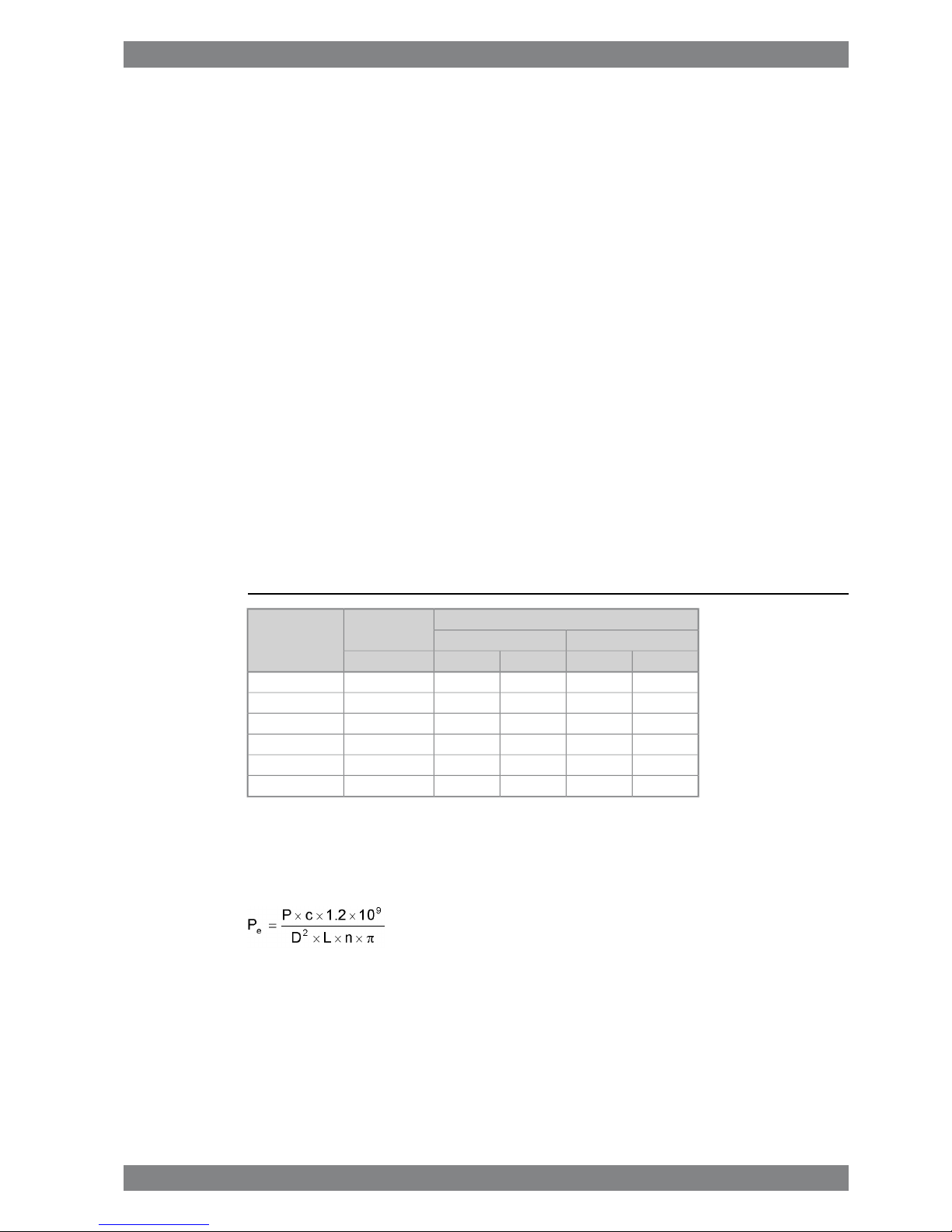
The mean effective pressure Pecan be calculated using the following formula:
where:
mean effective pressure [bar]Pe=
output per cylinder [kW]P =
engine speed [r/min]n =
cylinder diameter [mm]D =
length of piston stroke [mm]L =
operating cycle (4)c =
Wärtsilä 50DF Product Guide - a16 - 9 September 2016 1-1
1. Main Data and OutputsWärtsilä 50DF Product Guide
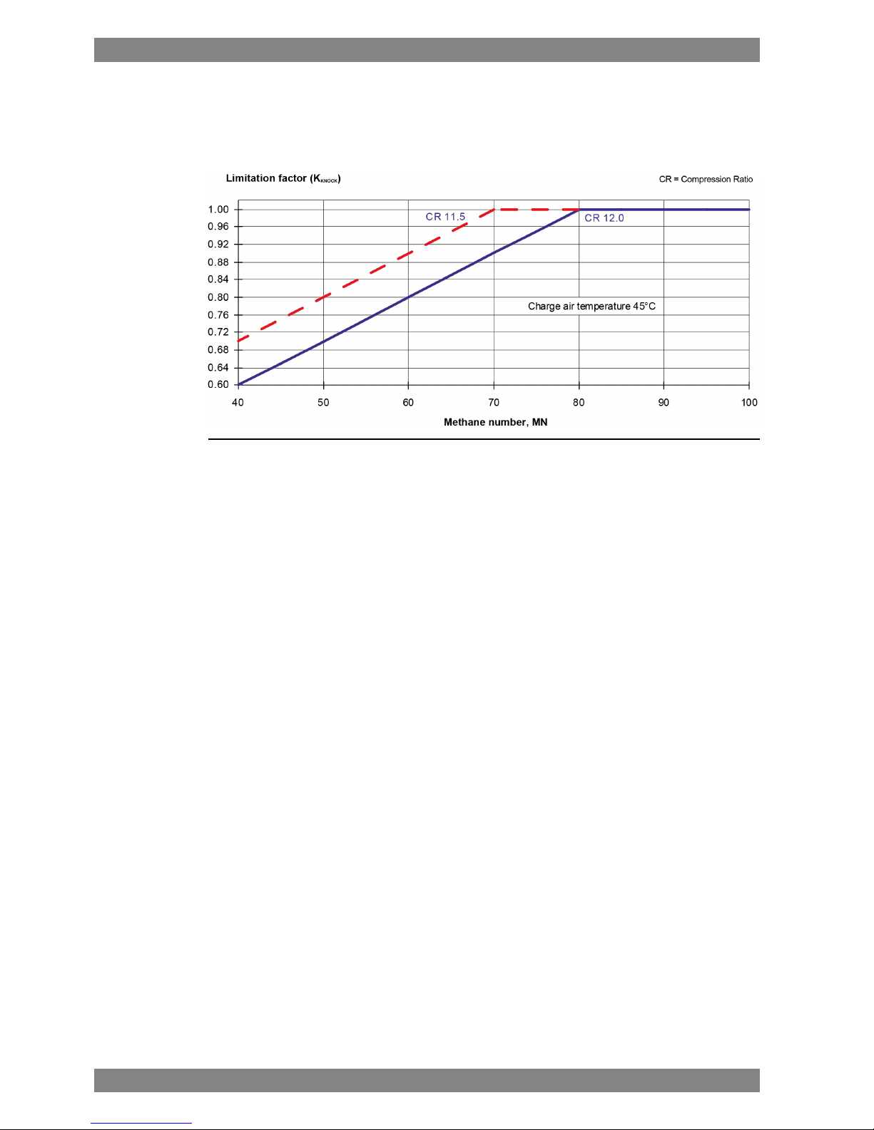
1.2 Output limitations in gas mode
1.2.1 Output limitations due to methane number
Fig 1-1 Output limitations due to methane number
Notes:
The dew point shall be calculated for the specific
site conditions. The minimum charge air temperature shall be above the dew point, otherwise condensation will occur in the charge air cooler.
Compensating a low methane number gas by
lowering the receiver temperature below 45°C is
not allowed.
Compensating a higher charge air temperature
than 45°C by a high methane number gas is not
allowed.
The charge air temperature is approximately 5°C
higher than the charge air coolant temperature at
rated load.
The engine can be optimized for a lower methane
number but that will affect the performance.
1-2 Wärtsilä 50DF Product Guide - a16 - 9 September 2016
Wärtsilä 50DF Product Guide1. Main Data and Outputs

1.2.2 Output limitations due to gas feed pressure and lower
heating value
Fig 1-2 Output limitation factor due to gas feed pressure / LHV
Notes:
No compensation (uprating) of the engine output
is allowed, neither for gas feed pressure higher
than required in the graph above nor lower heating
value above 36 MJ/m
3
N
.
The above given values for gas feed pressure
(absolute pressure) are at engine inlet. The pressure drop over the gas valve unit (GVU) is approx.
80 kPa.
Values given in m
3
N
are at 0°C and 101.3 kPa.
Wärtsilä 50DF Product Guide - a16 - 9 September 2016 1-3
1. Main Data and OutputsWärtsilä 50DF Product Guide

1.3 Reference conditions
The output is available within a range of ambient conditions and coolant temperatures specified
in the chapter Technical Data. The required fuel quality for maximum output is specified in the
section Fuel characteristics. For ambient conditions or fuel qualities outside the specification,
the output may have to be reduced.
The specific fuel consumption is stated in the chapter Technical Data. The statement applies
to engines operating in ambient conditions according to ISO 3046-1:2002 (E).
100 kPatotal barometric pressure
25°Cair temperature
30%relative humidity
25°Ccharge air coolant temperature
Correction factors for the fuel oil consumption in other ambient conditions are given in standard
ISO 3046-1:2002.
1.4 Operation in inclined position
Max. inclination angles at which the engine will operate satisfactorily.
15.0°
● Transverse inclination, permanent (list)
22.5°
● Transverse inclination, momentary (roll)
10.0°
● Permanent fore-and-aft inclinations
1-4 Wärtsilä 50DF Product Guide - a16 - 9 September 2016
Wärtsilä 50DF Product Guide1. Main Data and Outputs
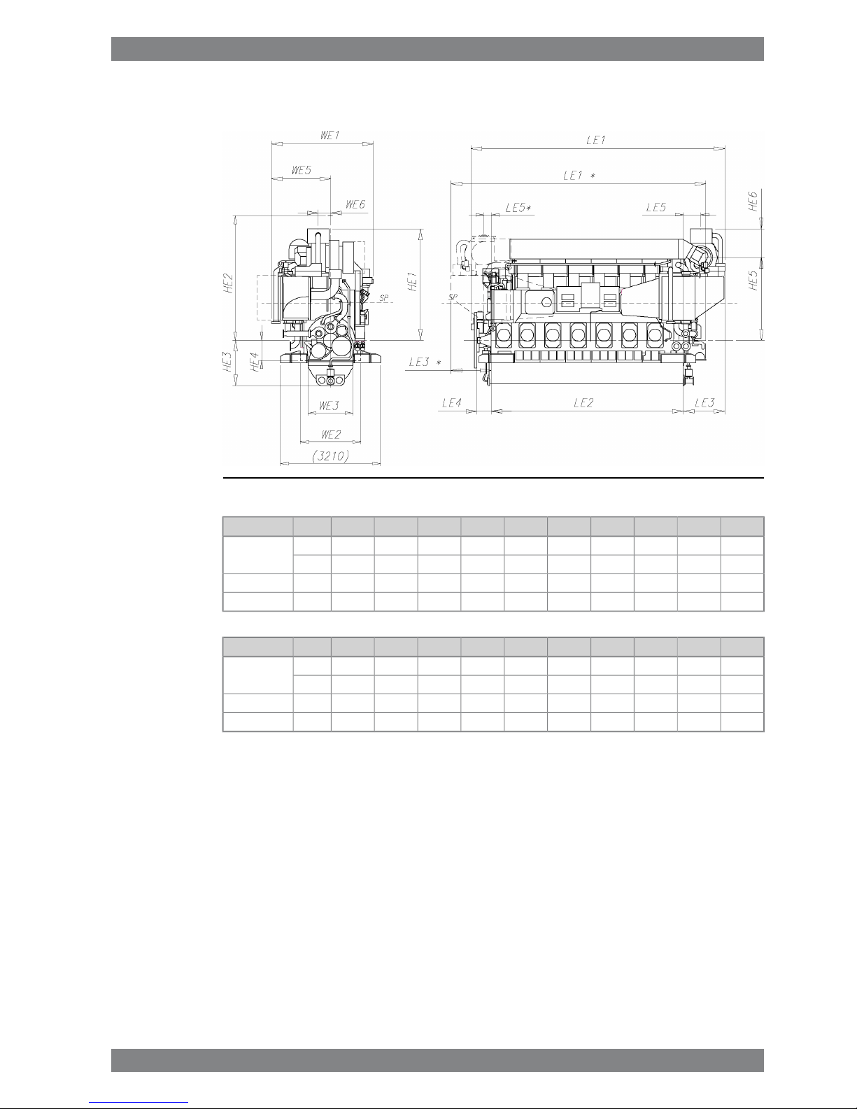
1.5 Dimensions and weights
Fig 1-3 In-line engines (DAAE000316d)
HE2HE1LE5*LE5LE4LE3*LE3LE2LE1*LE1TCEngine
4000358016055546012951295617083108205NA357W 6L50DF
4000347523055546012951295617083108120TPL71
40003920-700460-17757810-10270TPL76W 8L50DF
40003920-700460-17758630-11140TPL76W 9L50DF
WeightWE6WE5WE3WE2WE1HE6HE5HE4HE3TCEngine
96395189514451940327092526556501455NA357W 6L50DF
96420189514451940327079026856501455TPL71
1283402100144519403505110028206501455TPL76W 8L50DF
137.53402100144519403505110028206501455TPL76W 9L50DF
* TC in driving end
All dimensions in mm. Weights are dry engines, in metric tons, of rigidly mounted engines
without flywheel.
Wärtsilä 50DF Product Guide - a16 - 9 September 2016 1-5
1. Main Data and OutputsWärtsilä 50DF Product Guide
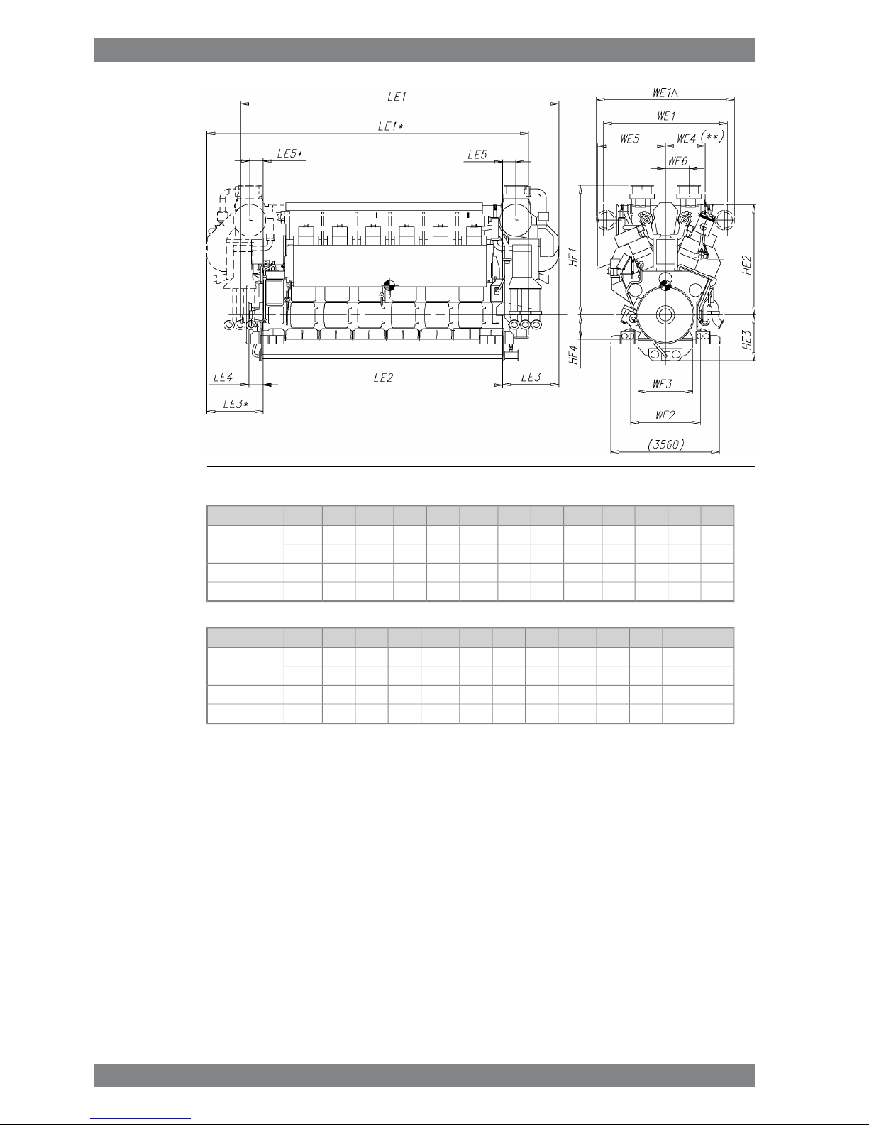
Fig 1-4 V-engines (DAAE000413c)
HE4HE3HE2HE1LE5*LE5LE4LE3*LE3LE2LE1*LE1TCEngine
8001500360040555005004601840184078501054010410NA357W 12V50DF
8001500360042404354354601840184078501054010425TPL71
80015003600440068068046023002300100501320013830TPL76W 16V50DF
800150036004400-680460-230011150-14180TPL76W 18V50DF
WeightWE6WE5WE4**WE4WE3WE2WE1ΔWE1HE6HE5TCEngine
17576522201300149518002290452038109253080NA357W 12V50DF
175770222013001495180022904525405511403100TPL71
224930222013001495180022905325473011003300TPL76W 16V50DF
244930222013001495180022905325473011003300TPL76W 18V50DF
* TC in driving end
** With monospex (exhaust manifold)
Δ With air suction branches
All dimensions in mm. Weights are dry engines, in metric tons, of rigidly mounted engines
without flywheel.
1-6 Wärtsilä 50DF Product Guide - a16 - 9 September 2016
Wärtsilä 50DF Product Guide1. Main Data and Outputs
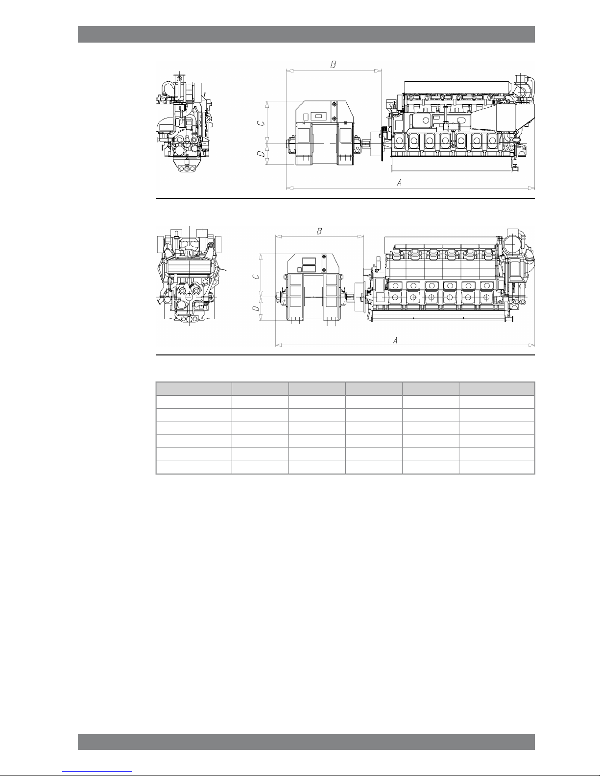
Fig 1-5 Example of total installation lengths, in-line engines (DAAE000489)
Fig 1-6 Example of total installation lengths, V-engines (DAAE000489)
Genset weight [ton]DCBAEngine
13810902235494012940W 6L50DF
17110202825506015060W 8L50DF
18510202825506015910W 9L50DF
23913652593525315475W 12V50DF
28815902050469017540W 16V50DF
31515902050469018500W 18V50DF
Values are indicative only and are based on Wärtsilä 50DF engine with built-on pumps and
turbocharger at free end of the engine.
Generator make and type will effect width, length, height and weight.
[All dimensions are in mm]
Wärtsilä 50DF Product Guide - a16 - 9 September 2016 1-7
1. Main Data and OutputsWärtsilä 50DF Product Guide

This page intentionally left blank

2. Operating Ranges
2.1 Engine operating range
Below nominal speed the load must be limited according to the diagrams in this chapter in
order to maintain engine operating parameters within acceptable limits. Operation in the
shaded area is permitted only temporarily during transients. Minimum speed is indicated in
the diagram, but project specific limitations may apply.
2.1.1 Controllable pitch propellers
An automatic load control system is required to protect the engine from overload. The load
control reduces the propeller pitch automatically, when a pre-programmed load versus speed
curve (“engine limit curve”) is exceeded, overriding the combinator curve if necessary. Engine
load is determined from measured shaft power and actual engine speed. The shaft power
meter is Wärtsilä supply.
The propulsion control must also include automatic limitation of the load increase rate.
Maximum loading rates can be found later in this chapter.
The propeller efficiency is highest at design pitch. It is common practice to dimension the
propeller so that the specified ship speed is attained with design pitch, nominal engine speed
and 85% output in the specified loading condition. The power demand from a possible shaft
generator or PTO must be taken into account. The 15% margin is a provision for weather
conditions and fouling of hull and propeller. An additional engine margin can be applied for
most economical operation of the engine, or to have reserve power.
Wärtsilä 50DF Product Guide - a16 - 9 September 2016 2-1
2. Operating RangesWärtsilä 50DF Product Guide
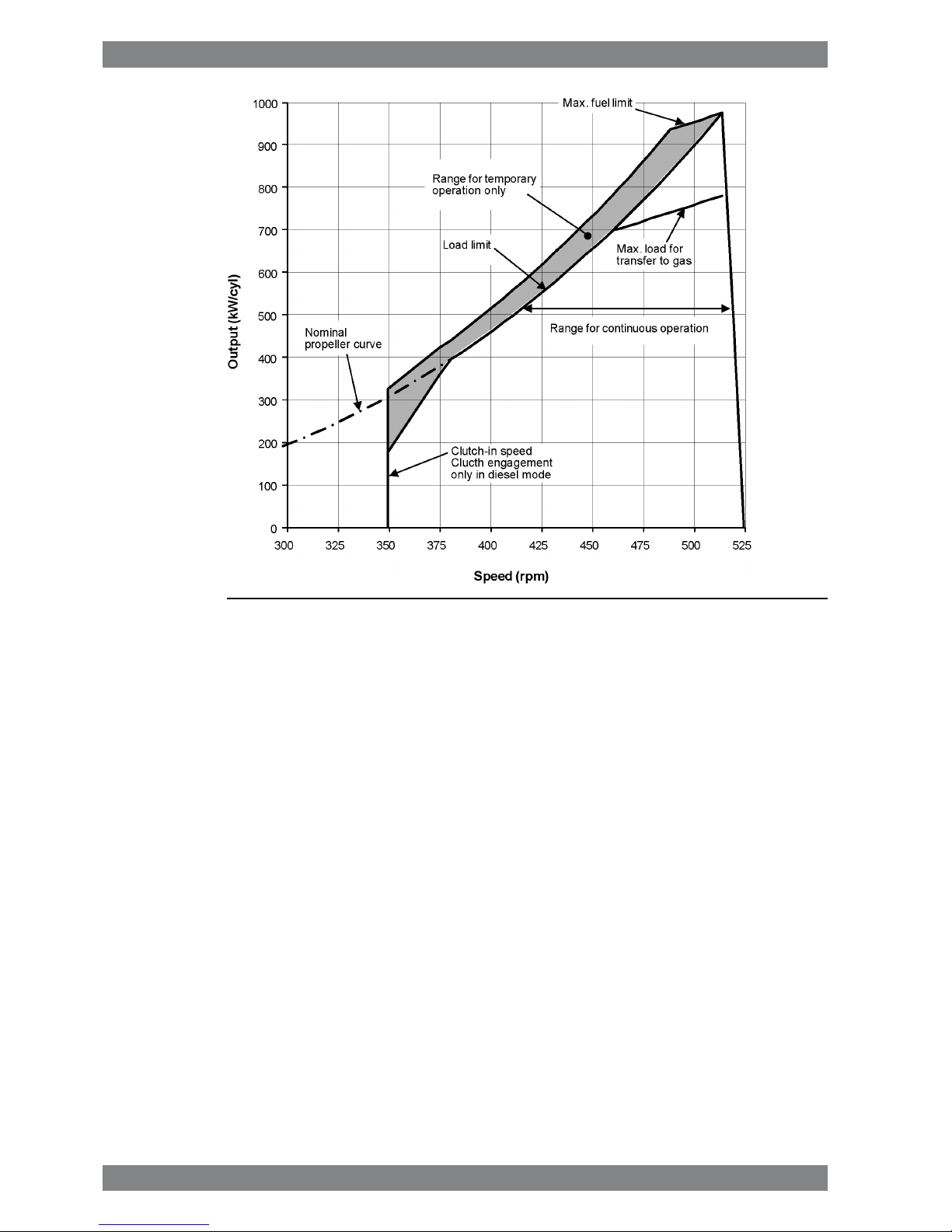
Fig 2-1 Operating field for CP-propeller, 975 kW/cyl, rated speed 514 rpm
Remarks: The maximum output may have to be reduced depending on gas properties and
gas pressure, refer to section "Derating of output in gas mode". The permissible output will
in such case be reduced with same percentage at all revolution speeds.
Restrictions for low load operation to be observed.
2.2 Loading capacity
Controlled load increase is essential for highly supercharged engines, because the turbocharger
needs time to accelerate before it can deliver the required amount of air. Sufficient time to
achieve even temperature distribution in engine components must also be ensured. Dual fuel
engines operating in gas mode require precise control of the air/fuel ratio, which makes
controlled load increase absolutely decisive for proper operation on gas fuel.
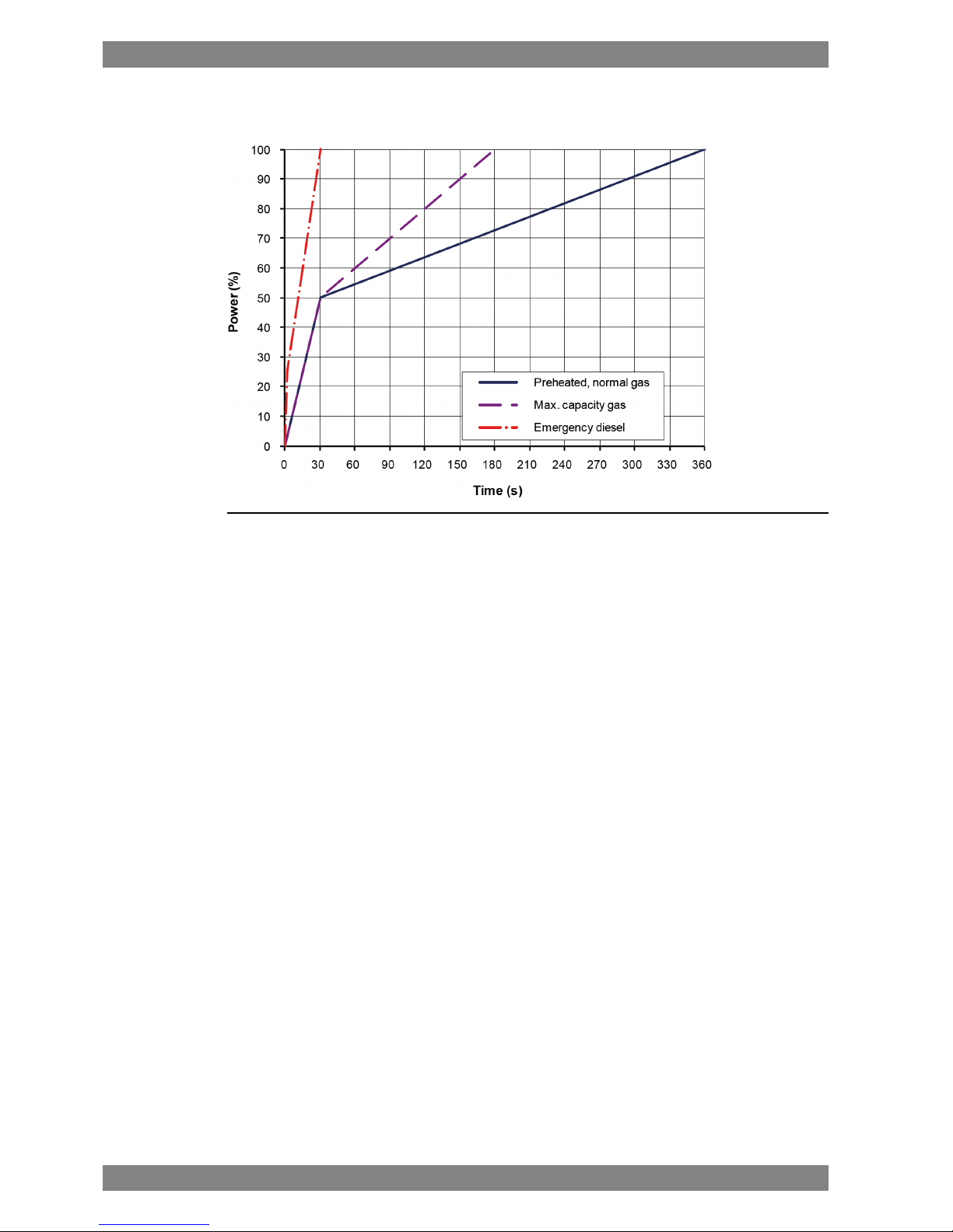
The loading ramp “preheated, normal gas” (see figures) can be used as the default loading
rate for both diesel and gas mode. If the control system has only one load increase ramp, then
the ramp for a preheated engine must be used. The HT-water temperature in a preheated
engine must be at least 60ºC, preferably 70ºC, and the lubricating oil temperature must be at
least 40ºC.
The loading ramp “max. capacity gas” indicates the maximum capability of the engine in gas
mode. Faster loading may result in alarms, knock and undesired trips to diesel. This ramp can
also be used as normal loading rate in diesel mode once the engine has attained normal
operating temperature.
The maximum loading rate “emergency diesel” is close to the maximum capability of the
engine in diesel mode. It shall not be used as the normal loading rate in diesel mode.
Emergency loading may only be possible by activating an emergency function, which generates
visual and audible alarms in the control room and on the bridge.
2-2 Wärtsilä 50DF Product Guide - a16 - 9 September 2016
Wärtsilä 50DF Product Guide2. Operating Ranges
The load should always be applied gradually in normal operation. Acceptable load increments
are smaller in gas mode than in diesel mode and also smaller at high load, which must be
taken into account in applications with sudden load changes. The time between load increments
must be such that the maximum loading rate is not exceeded. In the case of electric power
generation, the classification society shall be contacted at an early stage in the project regarding
system specifications and engine loading capacity.
Electric generators must be capable of 10% overload. The maximum engine output is 110%
in diesel mode and 100% in gas mode. Transfer to diesel mode takes place automatically in
case of overload. Lower than specified methane number may also result in automatic transfer
to diesel when operating close to 100% output. Expected variations in gas fuel quality and
momentary load level must be taken into account to ensure that gas operation can be
maintained in normal operation.
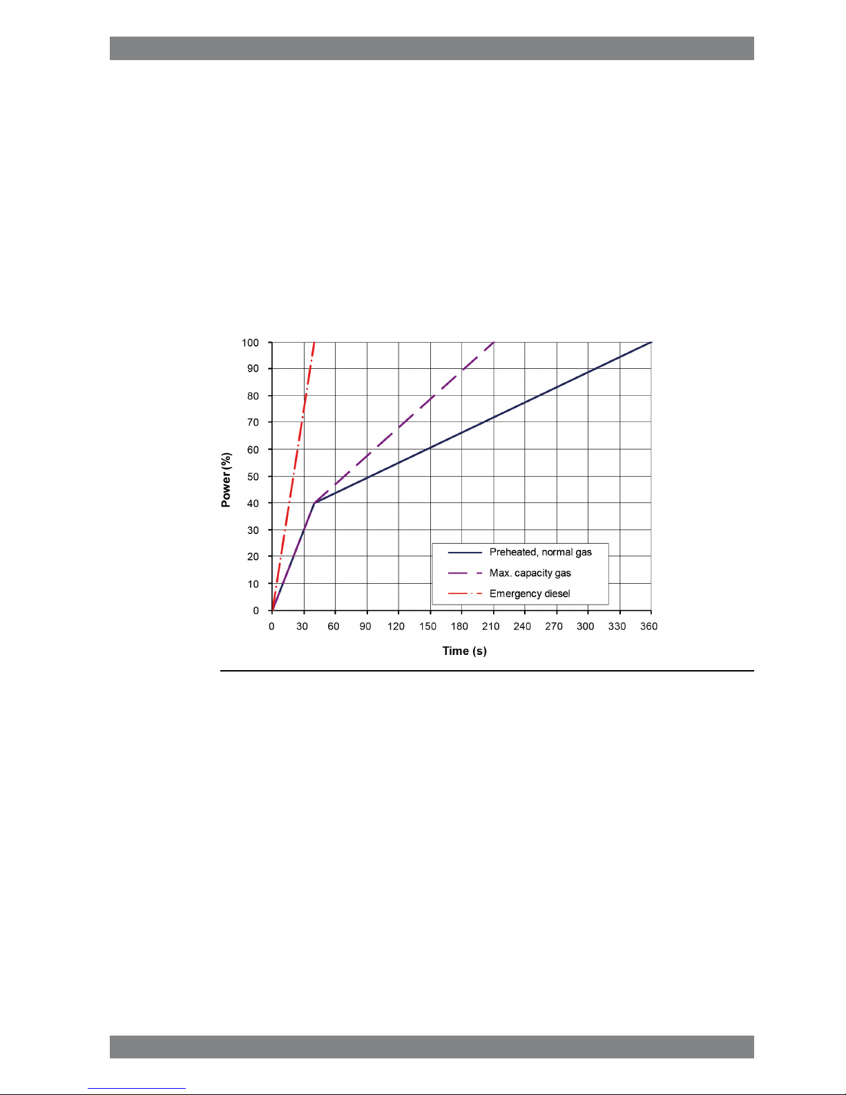
2.2.1 Mechanical propulsion, controllable pitch propeller (CPP)
Fig 2-2 Maximum load increase rates for variable speed engines
The propulsion control must not permit faster load reduction than 20 s from 100% to 0%
without automatic transfer to diesel first.
Wärtsilä 50DF Product Guide - a16 - 9 September 2016 2-3
2. Operating RangesWärtsilä 50DF Product Guide
2.2.2 Constant speed applications
Fig 2-3 Maximum load increase rates for engines operating at nominal speed
The propulsion control and the power management system must not permit faster load
reduction than 20 s from 100% to 0% without automatic transfer to diesel first.
In electric propulsion applications loading ramps are implemented both in the propulsion
control and in the power management system, or in the engine speed control in case
isochronous load sharing is applied. When the load sharing is based on speed droop, it must
be taken into account that the load increase rate of a recently connected generator is the sum
of the load transfer performed by the power management system and the load increase
performed by the propulsion control.
Maximum instant load steps
The electrical system must be designed so that tripping of breakers can be safely handled.
This requires that the engines are protected from load steps exceeding their maximum load
acceptance capability. If fast load shedding is complicated to implement or undesired, the
instant load step capacity can be increased with a fast acting signal that requests transfer to
diesel mode.
2-4 Wärtsilä 50DF Product Guide - a16 - 9 September 2016
Wärtsilä 50DF Product Guide2. Operating Ranges

Gas mode
Fig 2-4 Maximum instant load steps in % of MCR in gas mode
● Maximum step-wise load increases according to figure
● Steady-state frequency band ≤ 1.5 %
● Maximum speed drop 10 %
● Recovery time ≤ 10 s
● Time between load steps ≥ 30 s
● Maximum step-wise load reductions: 100-75-45-0%
Diesel mode
● Maximum step-wise load increase 33% of MCR
● Steady-state frequency band ≤ 1.0 %
● Maximum speed drop 10 %
● Recovery time ≤ 5 s
● Time between load steps ≥ 10 s
Start-up
A stand-by generator reaches nominal speed in 50-70 seconds after the start signal (check
of pilot fuel injection is always performed during a normal start).
With black-out start active nominal speed is reached in about 25 s (pilot fuel injection disabled).
The engine can be started with gas mode selected provided that the engine is preheated and
the air receiver temperature is at required level. It will then start on MDF and gas fuel will be
used as soon as the pilot check is completed and the gas supply system is ready.
Start and stop on heavy fuel is not restricted.
Wärtsilä 50DF Product Guide - a16 - 9 September 2016 2-5
2. Operating RangesWärtsilä 50DF Product Guide

2.3 Operation at low load and idling
Absolute idling (declutched main engine, disconnected generator):
● Maximum 10 minutes if the engine is to be stopped after the idling. 3-5 minutes idling
before stop is recommended.
● Maximum 2 hours on HFO if the engine is to be loaded after the idling.
● Maximum 8 hours on MDF or gas if the engine is to be loaded after the idling.
Operation below 20 % load on HFO or below 10 % load on MDF or gas:
● Maximum 100 hours continuous operation. At intervals of 100 operating hours the engine
must be loaded to min. 70% of the rated output for 1 hour.
● If operated longer than 30h in liquid fuel mode, the engine must be loaded to minimum
70% of rated output for 1 hour before transfer to gas.
● Before operating below 10% in gas mode the engine must run above 10% load for at least
10 minutes. It is however acceptable to change to gas mode directly after the engine has
started, provided that the charge air temperature is above 55°C.
Operation above 20 % load on HFO or above 10 % load on MDF or gas:
● No restrictions.
2.4 Low air temperature
The minimum inlet air temperature of 5°C applies, when the inlet air is taken from the engine
room.
Engines can run in colder conditions at high loads (suction air lower than 5°C) provided that
special provisions are considered to prevent too low HT-water temperature and T/C surge.
For start, idling and low load operations (Ch 2.3), suction air temperature shall be maintained
at 5°C.
If necessary, the preheating arrangement can be designed to heat the running engine (capacity
to be checked).
For further guidelines, see chapter Combustion air system design.
2-6 Wärtsilä 50DF Product Guide - a16 - 9 September 2016
Wärtsilä 50DF Product Guide2. Operating Ranges
3. Technical Data
3.1 Introduction
This chapter contains technical data of the engine (heat balance, flows, pressures etc.) for
design of ancillary systems. Further design criteria for external equipment and system layouts
are presented in the respective chapter.
Separate data is given for engines driving propellers “ME” and engines driving generators
“DE”.
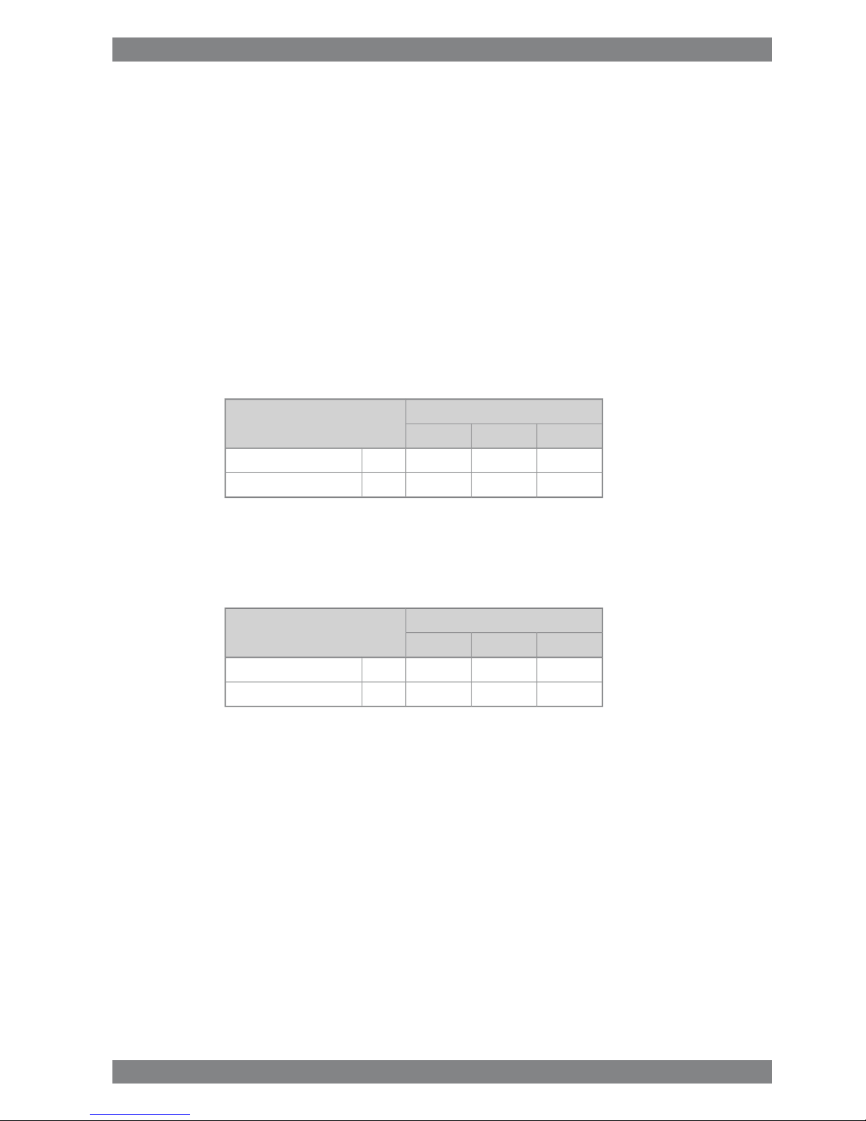
3.1.1 Engine driven pumps
The basic fuel consumption given in the technical data tables are with engine driven lubricating
oil and cooling water pumps. The decrease in fuel consumption, without engine driven pumps,
in g/kWh is given in the table below:
Engine load [%]Decrease in fuel consumption
5075100
432g/kWhLubricating oil pump
21.61g/kWhHT- and LT-water pump
For calculation of gas consumption adjusted without engine driven pumps; use values in the
table below calculated using above table and with Methane (CH4) as reference fuel gas, with
lower calorific value of 50 MJ/kg.
Engine load [%]Decrease in gas consumption
5075100
200150100kJ/kWhLubricating oil pump
1008050kJ/kWhHT- and LT-water pump
Wärtsilä 50DF Product Guide - a16 - 9 September 2016 3-1
3. Technical DataWärtsilä 50DF Product Guide

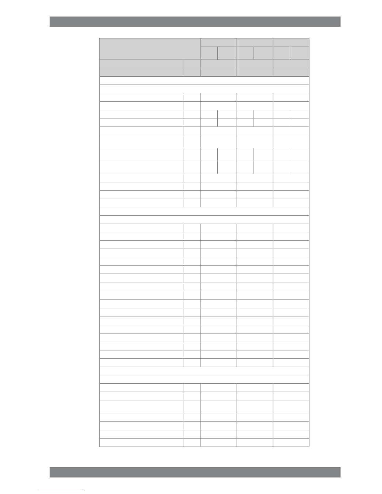
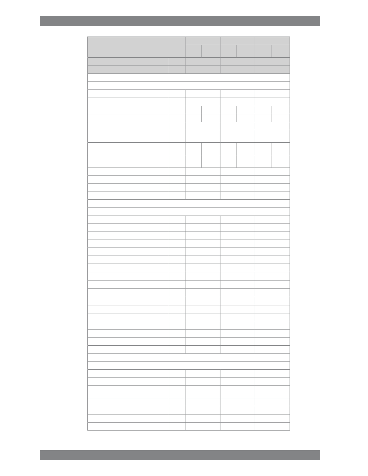
3.2 Wärtsilä 6L50DF
MEDEDE
Wärtsilä 6L50DF
Diesel
mode
Gas
mode
Diesel
mode
Gas
mode
Diesel
mode
Gas
mode
975975950kWCylinder output
514514500rpmEngine speed
585058505700kWEngine output
2.02.02.0MPaMean effective pressure
Tier 2Tier 3Tier 2Tier 3Tier 2Tier 3IMO compliance
Combustion air system (Note 1)
11.09.211.39.211.39.2kg/sFlow at 100% load
454545°CTemperature at turbocharger intake, max.
504550455045°CTemperature after air cooler, nom. (TE 601)
Exhaust gas system
12.09.611.49.610.89.0kg/sFlow at 100% load
9.07.29.07.29.07.2kg/sFlow at 75% load
7.26.06.65.46.05.4kg/sFlow at 50% load
325379347378345375°CTemperature after turbocharger at 100% load
(TE 517)
332401330428332424°CTemperature after turbocharger at 75% load
(TE 517)
300386373433377430°CTemperature after turbocharger at 50% load
(TE 517)
444kPaBackpressure, max.
858801851800827773mmCalculated exhaust diameter for 35 m/s
Heat balance at 100% load (Note 2)
10206841008936966654kWJacket water, HT-circuit
136894813026781212900kWCharge air, HT-circuit
696462630462612450kWCharge air, LT-circuit
762480750474726462kWLubricating oil, LT-circuit
180162180162168156kWRadiation
Fuel consumption (Note 3)
-7460-7440-7410kJ/kWhTotal energy consumption at 100% load
-7580-7780-7740kJ/kWhTotal energy consumption at 75% load
-8080-8440-8410kJ/kWhTotal energy consumption at 50% load
-7412-7397-7365kJ/kWhFuel gas consumption at 100% load
-7511-7710-7677kJ/kWhFuel gas consumption at 75% load
-7979-8336-8300kJ/kWhFuel gas consumption at 50% load
1891.01891.01871.0g/kWhFuel oil consumption at 100% load
1851.51881.51871.5g/kWhFuel oil consumption at 75% load
1932.31982.41982.4g/kWhFuel oil consumption 50% load
Fuel gas system (Note 4)
-472-472-472kPa (a)Gas pressure at engine inlet, min (PT901)
-592-592-592kPa (a)Gas pressure to Gas Valve unit, min
-0...60-0...60-0...60°CGas temperature before Gas Valve Unit
3-2 Wärtsilä 50DF Product Guide - a16 - 9 September 2016
Wärtsilä 50DF Product Guide3. Technical Data
MEDEDE
Wärtsilä 6L50DF
Diesel
mode
Gas
mode
Diesel
mode
Gas
mode
Diesel
mode
Gas
mode
975975950kWCylinder output
514514500rpmEngine speed
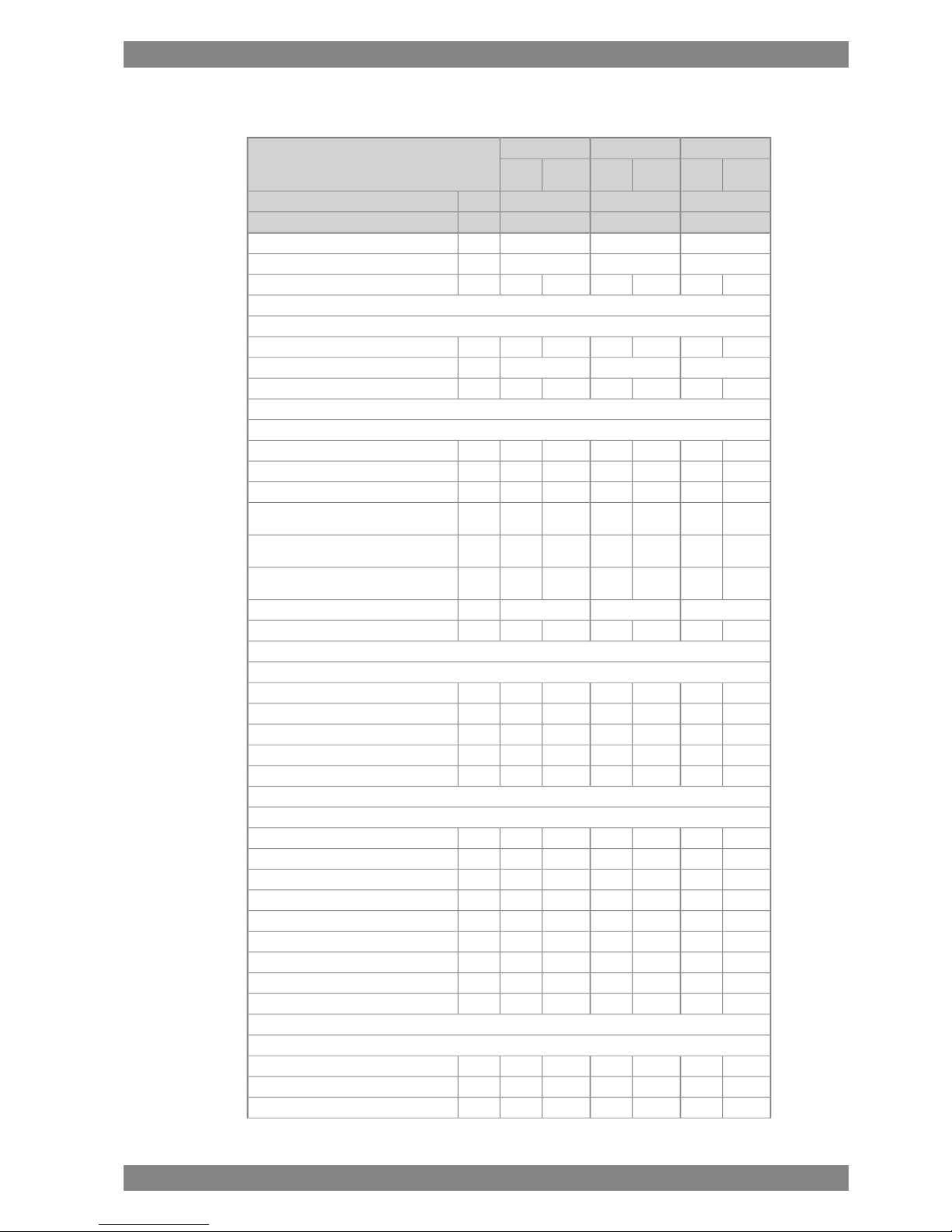
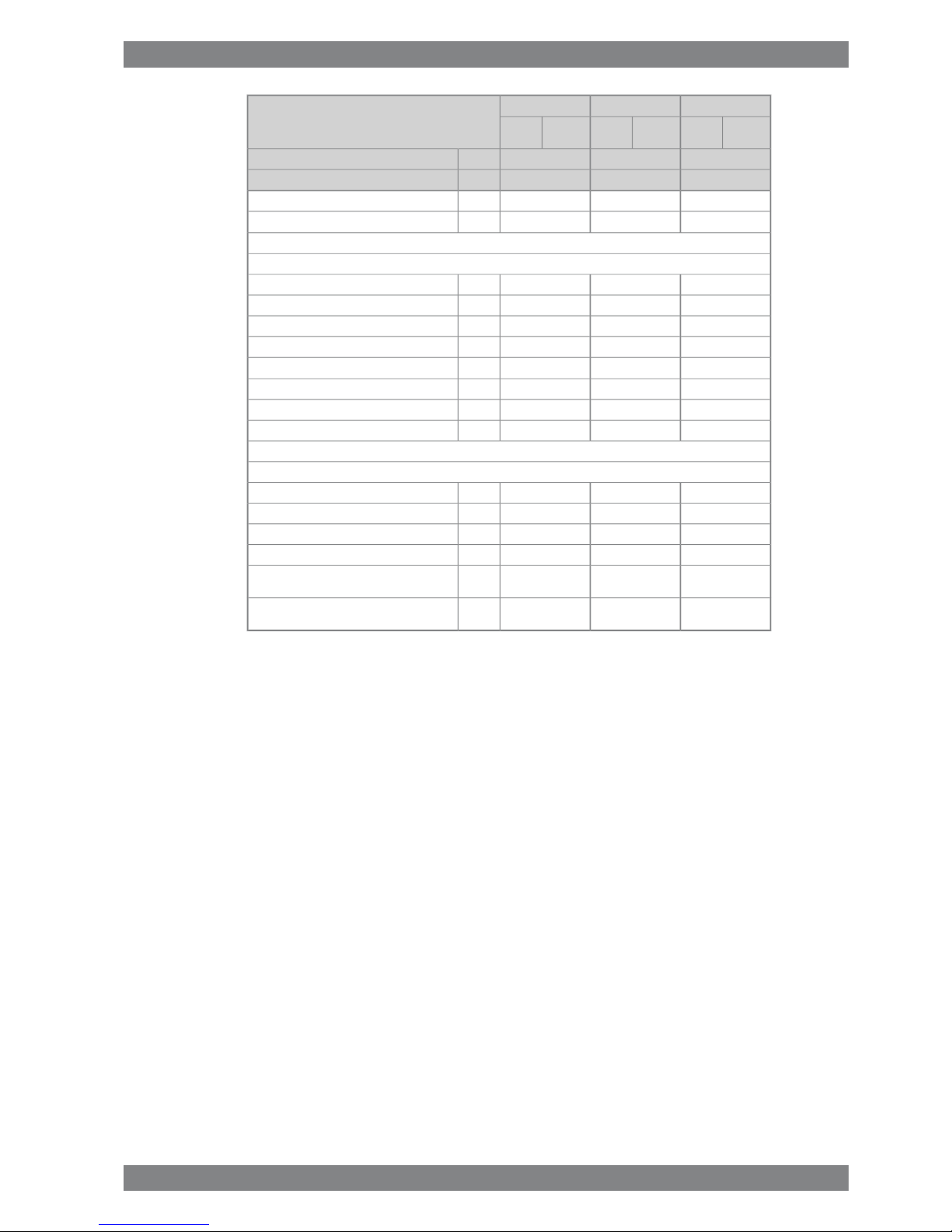
Fuel oil system
800±50800±50800±50kPaPressure before injection pumps (PT 101)
6.26.26.0m3/hFuel oil flow to engine, approx
16...24-16...24-16...24-cStHFO viscosity before the engine
140-140-140-°CMax. HFO temperature before engine (TE 101)
2.02.02.0cStMDF viscosity, min.
454545°CMax. MDF temperature before engine (TE
101)
4.7-4.5-4.5-kg/hLeak fuel quantity (HFO), clean fuel at 100%
load
23.311.722.612.022.612.0kg/hLeak fuel quantity (MDF), clean fuel at 100%
load
2...112...112...11cStPilot fuel (MDF) viscosity before the engine
400...800400...800400...800kPaPilot fuel pressure at engine inlet (PT 112)
150150150kPaPilot fuel outlet pressure, max
276276276kg/hPilot fuel return flow at 100% load
Lubricating oil system (Note 5)
400400400kPaPressure before bearings, nom. (PT 201)
800800800kPaPressure after pump, max.
404040kPaSuction ability, including pipe loss, max.
808080kPaPriming pressure, nom. (PT 201)
636363°CTemperature before bearings, nom. (TE 201)
787878°CTemperature after engine, approx.
157153149m3/hPump capacity (main), engine driven
140140140m3/hPump capacity (main), electrically driven
120120120m3/hOil flow through engine
34.0 / 34.034.0 / 34.034.0 / 34.0m3/hPriming pump capacity (50/60Hz)
888m
3
Oil volume in separate system oil tank
0.50.50.5g/kWhOil consumption at 100% load, approx.
130013001300l/minCrankcase ventilation flow rate at full load
14.614.614.6m
3
Crankcase volume
500500500PaCrankcase ventilation backpressure, max.
8.5...9.58.5...9.58.5...9.5lOil volume in turning device
1.41.41.4lOil volume in speed governor
HT cooling water system
250 + static250 + static250 + statickPaPressure at engine, after pump, nom. (PT 401)
480480480kPaPressure at engine, after pump, max. (PT 401)
747474°CTemperature before cylinders, approx. (TE
401)
969696°CTemperature after charge air cooler, nom.
135135135m3/hCapacity of engine driven pump, nom.
505050kPaPressure drop over engine, total
150150150kPaPressure drop in external system, max.
Wärtsilä 50DF Product Guide - a16 - 9 September 2016 3-3
3. Technical DataWärtsilä 50DF Product Guide

MEDEDE
Wärtsilä 6L50DF
Diesel
mode
Gas
mode
Diesel
mode
Gas
mode
Diesel
mode
Gas
mode
975975950kWCylinder output
514514500rpmEngine speed
70...15070...15070...150kPaPressure from expansion tank
0.950.950.95m
3
Water volume in engine
LT cooling water system
250+ static250+ static250+ statickPaPressure at engine, after pump, nom. (PT 471)
440440440kPaPressure at engine, after pump, max. (PT 471)
555555°CTemperature before engine, max. (TE 471)
363636°CTemperature before engine, min. (TE 471)
135135135m3/hCapacity of engine driven pump, nom.
303030kPaPressure drop over charge air cooler
200200200kPaPressure drop in external system, max.
70...15070...15070...150kPaPressure from expansion tank
Starting air system (Note 6)
300030003000kPaPressure, nom. (PT 301)
100010001000kPaPressure at engine during start, min. (20 °C)
300030003000kPaPressure, max. (PT 301)
180018001800kPaLow pressure limit in starting air vessel
3.63.63.6Nm
3
Consumption per start at 20 °C (successful
start)
4.34.34.3Nm
3
Consumption per start at 20 °C (with
slowturn)
Notes:
At Gas LHV 49620kJ/kgNote 1
At 100% output and nominal speed. The figures are valid for ambient conditions according to ISO 15550, except for LTwater temperature, which is 35ºC in gas operation and 45ºC in back-up fuel operation. And with engine driven water,
lube oil and pilot fuel pumps.
Note 2
According to ISO 15550, lower calorific value 42700 kJ/kg, with engine driven pumps (two cooling water + one lubricating
oil pumps). Tolerance 5%. Gas Lower heating value >28 MJ/m3N and Methane Number High (>80). The fuel consumption
BSEC and SFOC are guaranteed at 100% load and the values at other loads are given for indication only.
Note 3
Fuel gas pressure given at LHV ≥ 36MJ/m³N. Required fuel gas pressure depends on fuel gas LHV and need to be increased
for lower LHV's. Pressure drop in external fuel gas system to be considered. See chapter Fuel system for further information.
Note 4
Lubricating oil treatment losses and oil changes are not included in oil consumption. The lubricating oil volume of the
governor is depending of the governor type.
Note 5
At manual starting the consumption may be 2...3 times lower.Note 6
ME = Engine driving propeller, variable speed
DE = Diesel-Electric engine driving generator
Subject to revision without notice.
3-4 Wärtsilä 50DF Product Guide - a16 - 9 September 2016
Wärtsilä 50DF Product Guide3. Technical Data
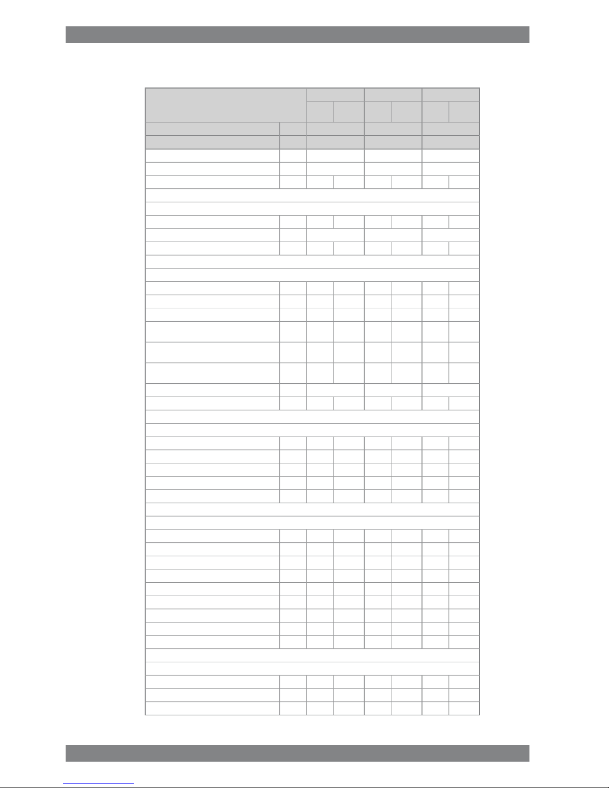
3.3 Wärtsilä 8L50DF
MEDEDE
Wärtsilä 8L50DF
Diesel
mode
Gas
mode
Diesel
mode
Gas
mode
Diesel
mode
Gas
mode
975975950kWCylinder output
514514500rpmEngine speed
780078007600kWEngine output
2.02.02.0MPaMean effective pressure
Tier 2Tier 3Tier 2Tier 3Tier 2Tier 3IMO compliance
Combustion air system (Note 1)
14.612.215.012.215.012.2kg/sFlow at 100% load
454545°CTemperature at turbocharger intake, max.
504550455045°CTemperature after air cooler, nom. (TE 601)
Exhaust gas system
16.012.815.212.814.412.0kg/sFlow at 100% load
12.09.612.09.612.09.6kg/sFlow at 75% load
9.68.08.87.28.07.2kg/sFlow at 50% load
325379347378345375°CTemperature after turbocharger at 100% load
(TE 517)
332401330428332424°CTemperature after turbocharger at 75% load
(TE 517)
300386373433377430°CTemperature after turbocharger at 50% load
(TE 517)
444kPaBackpressure, max.
990925983924955893mmCalculated exhaust diameter for 35 m/s
Heat balance at 100% load (Note 2)
1360912134412481288872kWJacket water, HT-circuit
18241264173690416161200kWCharge air, HT-circuit
928616840616816600kWCharge air, LT-circuit
10166401000632968616kWLubricating oil, LT-circuit
240216240216224208kWRadiation
Fuel consumption (Note 3)
-7460-7440-7410kJ/kWhTotal energy consumption at 100% load
-7580-7780-7740kJ/kWhTotal energy consumption at 75% load
-8080-8440-8410kJ/kWhTotal energy consumption at 50% load
-7412-7397-7365kJ/kWhFuel gas consumption at 100% load
-7511-7710-7677kJ/kWhFuel gas consumption at 75% load
-7979-8336-8300kJ/kWhFuel gas consumption at 50% load
1891.01891.01871.0g/kWhFuel oil consumption at 100% load
1851.51881.51871.5g/kWhFuel oil consumption at 75% load
1932.31982.41982.4g/kWhFuel oil consumption 50% load
Fuel gas system (Note 4)
-472-472-472kPa (a)Gas pressure at engine inlet, min (PT901)
-592-592-592kPa (a)Gas pressure to Gas Valve unit, min
-0...60-0...60-0...60°CGas temperature before Gas Valve Unit
Wärtsilä 50DF Product Guide - a16 - 9 September 2016 3-5
3. Technical DataWärtsilä 50DF Product Guide
MEDEDE
Wärtsilä 8L50DF
Diesel
mode
Gas
mode
Diesel
mode
Gas
mode
Diesel
mode
Gas
mode
975975950kWCylinder output
514514500rpmEngine speed
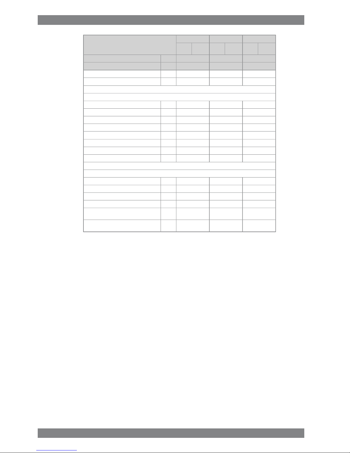
Fuel oil system
800±50800±50800±50kPaPressure before injection pumps (PT 101)
8.38.38.0m3/hFuel oil flow to engine, approx
16...24-16...24-16...24-cStHFO viscosity before the engine
140-140-140-°CMax. HFO temperature before engine (TE 101)
2.02.02.0cStMDF viscosity, min.
454545°CMax. MDF temperature before engine (TE
101)
6.2-6.0-6.0-kg/hLeak fuel quantity (HFO), clean fuel at 100%
load
31.115.530.116.030.116.0kg/hLeak fuel quantity (MDF), clean fuel at 100%
load
2...112...112...11cStPilot fuel (MDF) viscosity before the engine
400...800400...800400...800kPaPilot fuel pressure at engine inlet (PT 112)
150150150kPaPilot fuel outlet pressure, max
284284284kg/hPilot fuel return flow at 100% load
Lubricating oil system (Note 5)
400400400kPaPressure before bearings, nom. (PT 201)
800800800kPaPressure after pump, max.
404040kPaSuction ability, including pipe loss, max.
808080kPaPriming pressure, nom. (PT 201)
636363°CTemperature before bearings, nom. (TE 201)
787878°CTemperature after engine, approx.
198153149m3/hPump capacity (main), engine driven
145145145m3/hPump capacity (main), electrically driven
125125125m3/hOil flow through engine
45.0 / 45.045.0 / 45.045.0 / 45.0m3/hPriming pump capacity (50/60Hz)
111111m
3
Oil volume in separate system oil tank
0.50.50.5g/kWhOil consumption at 100% load, approx.
150015001500l/minCrankcase ventilation flow rate at full load
19.519.519.5m
3
Crankcase volume
500500500PaCrankcase ventilation backpressure, max.
8.5...9.58.5...9.58.5...9.5lOil volume in turning device
1.41.41.4lOil volume in speed governor
HT cooling water system
250 + static250 + static250 + statickPaPressure at engine, after pump, nom. (PT 401)
480480480kPaPressure at engine, after pump, max. (PT 401)
747474°CTemperature before cylinders, approx. (TE
401)
969696°CTemperature after charge air cooler, nom.
180180180m3/hCapacity of engine driven pump, nom.
505050kPaPressure drop over engine, total
150150150kPaPressure drop in external system, max.
3-6 Wärtsilä 50DF Product Guide - a16 - 9 September 2016
Wärtsilä 50DF Product Guide3. Technical Data
MEDEDE
Wärtsilä 8L50DF
Diesel
mode
Gas
mode
Diesel
mode
Gas
mode
Diesel
mode
Gas
mode
975975950kWCylinder output
514514500rpmEngine speed
70...15070...15070...150kPaPressure from expansion tank
1.351.351.35m
3
Water volume in engine
LT cooling water system
250+ static250+ static250+ statickPaPressure at engine, after pump, nom. (PT 471)
440440440kPaPressure at engine, after pump, max. (PT 471)
555555°CTemperature before engine, max. (TE 471)
363636°CTemperature before engine, min. (TE 471)
180180180m3/hCapacity of engine driven pump, nom.
303030kPaPressure drop over charge air cooler
200200200kPaPressure drop in external system, max.
70...15070...15070...150kPaPressure from expansion tank
Starting air system (Note 6)
300030003000kPaPressure, nom. (PT 301)
100010001000kPaPressure at engine during start, min. (20 °C)
300030003000kPaPressure, max. (PT 301)
180018001800kPaLow pressure limit in starting air vessel
4.84.84.8Nm
3
Consumption per start at 20 °C (successful
start)
5.85.85.8Nm
3
Consumption per start at 20 °C (with
slowturn)
Notes:
At Gas LHV 49620kJ/kgNote 1
At 100% output and nominal speed. The figures are valid for ambient conditions according to ISO 15550, except for LTwater temperature, which is 35ºC in gas operation and 45ºC in back-up fuel operation. And with engine driven water,
lube oil and pilot fuel pumps.
Note 2
According to ISO 15550, lower calorific value 42700 kJ/kg, with engine driven pumps (two cooling water + one lubricating
oil pumps). Tolerance 5%. Gas Lower heating value >28 MJ/m3N and Methane Number High (>80). The fuel consumption
BSEC and SFOC are guaranteed at 100% load and the values at other loads are given for indication only.
Note 3
Fuel gas pressure given at LHV ≥ 36MJ/m³N. Required fuel gas pressure depends on fuel gas LHV and need to be increased
for lower LHV's. Pressure drop in external fuel gas system to be considered. See chapter Fuel system for further information.
Note 4
Lubricating oil treatment losses and oil changes are not included in oil consumption. The lubricating oil volume of the
governor is depending of the governor type.
Note 5
At manual starting the consumption may be 2...3 times lower.Note 6
ME = Engine driving propeller, variable speed
DE = Diesel-Electric engine driving generator
Subject to revision without notice.
Wärtsilä 50DF Product Guide - a16 - 9 September 2016 3-7
3. Technical DataWärtsilä 50DF Product Guide
3.4 Wärtsilä 9L50DF
MEDEDE
Wärtsilä 9L50DF
Diesel
mode
Gas
mode
Diesel
mode
Gas
mode
Diesel
mode
Gas
mode
975975950kWCylinder output
514514500rpmEngine speed
877587758550kWEngine output
2.02.02.0MPaMean effective pressure
Tier 2Tier 3Tier 2Tier 3Tier 2Tier 3IMO compliance
Combustion air system (Note 1)
16.413.716.913.716.913.7kg/sFlow at 100% load
454545°CTemperature at turbocharger intake, max.
504550455045°CTemperature after air cooler, nom. (TE 601)
Exhaust gas system
18.014.417.114.416.213.5kg/sFlow at 100% load
13.510.813.510.813.510.8kg/sFlow at 75% load
10.89.09.98.19.08.1kg/sFlow at 50% load
325379347378345375°CTemperature after turbocharger at 100% load
(TE 517)
332401330428332424°CTemperature after turbocharger at 75% load
(TE 517)
300386373433377430°CTemperature after turbocharger at 50% load
(TE 517)
444kPaBackpressure, max.
105098110429801013947mmCalculated exhaust diameter for 35 m/s
Heat balance at 100% load (Note 2)
15301026151214041449981kWJacket water, HT-circuit
205214221953101718181350kWCharge air, HT-circuit
1044693945693918675kWCharge air, LT-circuit
114372011257111089693kWLubricating oil, LT-circuit
270243270243252234kWRadiation
Fuel consumption (Note 3)
-7460-7440-7410kJ/kWhTotal energy consumption at 100% load
-7580-7780-7740kJ/kWhTotal energy consumption at 75% load
-8080-8440-8410kJ/kWhTotal energy consumption at 50% load
-7412-7397-7365kJ/kWhFuel gas consumption at 100% load
-7511-7710-7677kJ/kWhFuel gas consumption at 75% load
-7979-8336-8300kJ/kWhFuel gas consumption at 50% load
1891.01891.01871.0g/kWhFuel oil consumption at 100% load
1851.51881.51871.5g/kWhFuel oil consumption at 75% load
1932.31982.41982.4g/kWhFuel oil consumption 50% load
Fuel gas system (Note 4)
-472-472-472kPa (a)Gas pressure at engine inlet, min (PT901)
-592-592-592kPa (a)Gas pressure to Gas Valve unit, min
-0...60-0...60-0...60°CGas temperature before Gas Valve Unit
3-8 Wärtsilä 50DF Product Guide - a16 - 9 September 2016
Wärtsilä 50DF Product Guide3. Technical Data

MEDEDE
Wärtsilä 9L50DF
Diesel
mode
Gas
mode
Diesel
mode
Gas
mode
Diesel
mode
Gas
mode
975975950kWCylinder output
514514500rpmEngine speed
Fuel oil system
800±50800±50800±50kPaPressure before injection pumps (PT 101)
9.39.39.0m3/hFuel oil flow to engine, approx
16...24-16...24-16...24-cStHFO viscosity before the engine
140-140-140-°CMax. HFO temperature before engine (TE 101)
2.02.02.0cStMDF viscosity, min.
454545°CMax. MDF temperature before engine (TE
101)
7.0-6.8-6.8-kg/hLeak fuel quantity (HFO), clean fuel at 100%
load
35.017.533.918.033.918.0kg/hLeak fuel quantity (MDF), clean fuel at 100%
load
2...112...112...11cStPilot fuel (MDF) viscosity before the engine
400...800400...800400...800kPaPilot fuel pressure at engine inlet (PT 112)
150150150kPaPilot fuel outlet pressure, max
288288288kg/hPilot fuel return flow at 100% load
Lubricating oil system (Note 5)
400400400kPaPressure before bearings, nom. (PT 201)
800800800kPaPressure after pump, max.
404040kPaSuction ability, including pipe loss, max.
808080kPaPriming pressure, nom. (PT 201)
636363°CTemperature before bearings, nom. (TE 201)
787878°CTemperature after engine, approx.
198162157m3/hPump capacity (main), engine driven
160160160m3/hPump capacity (main), electrically driven
130130130m3/hOil flow through engine
51.0 / 51.051.0 / 51.051.0 / 51.0m3/hPriming pump capacity (50/60Hz)
121212m
3
Oil volume in separate system oil tank
0.50.50.5g/kWhOil consumption at 100% load, approx.
190019001900l/minCrankcase ventilation flow rate at full load
22.022.022.0m
3
Crankcase volume
500500500PaCrankcase ventilation backpressure, max.
68.0...70.068.0...70.068.0...70.0lOil volume in turning device
1.41.41.4lOil volume in speed governor
HT cooling water system
250 + static250 + static250 + statickPaPressure at engine, after pump, nom. (PT 401)
480480480kPaPressure at engine, after pump, max. (PT 401)
747474°CTemperature before cylinders, approx. (TE
401)
969696°CTemperature after charge air cooler, nom.
200200200m3/hCapacity of engine driven pump, nom.
505050kPaPressure drop over engine, total
150150150kPaPressure drop in external system, max.
Wärtsilä 50DF Product Guide - a16 - 9 September 2016 3-9
3. Technical DataWärtsilä 50DF Product Guide
MEDEDE
Wärtsilä 9L50DF
Diesel
mode
Gas
mode
Diesel
mode
Gas
mode
Diesel
mode
Gas
mode
975975950kWCylinder output
514514500rpmEngine speed
70...15070...15070...150kPaPressure from expansion tank
1.51.51.5m
3
Water volume in engine
LT cooling water system
250+ static250+ static250+ statickPaPressure at engine, after pump, nom. (PT 471)
440440440kPaPressure at engine, after pump, max. (PT 471)
555555°CTemperature before engine, max. (TE 471)
363636°CTemperature before engine, min. (TE 471)
200200200m3/hCapacity of engine driven pump, nom.
303030kPaPressure drop over charge air cooler
200200200kPaPressure drop in external system, max.
70...15070...15070...150kPaPressure from expansion tank
Starting air system (Note 6)
300030003000kPaPressure, nom. (PT 301)
100010001000kPaPressure at engine during start, min. (20 °C)
300030003000kPaPressure, max. (PT 301)
180018001800kPaLow pressure limit in starting air vessel
5.45.45.4Nm
3
Consumption per start at 20 °C (successful
start)
6.56.56.5Nm
3
Consumption per start at 20 °C (with
slowturn)
Notes:
At Gas LHV 49620kJ/kgNote 1
At 100% output and nominal speed. The figures are valid for ambient conditions according to ISO 15550, except for LTwater temperature, which is 35ºC in gas operation and 45ºC in back-up fuel operation. And with engine driven water,
lube oil and pilot fuel pumps.
Note 2
According to ISO 15550, lower calorific value 42700 kJ/kg, with engine driven pumps (two cooling water + one lubricating
oil pumps). Tolerance 5%. Gas Lower heating value >28 MJ/m3N and Methane Number High (>80). The fuel consumption
BSEC and SFOC are guaranteed at 100% load and the values at other loads are given for indication only.
Note 3
Fuel gas pressure given at LHV ≥ 36MJ/m³N. Required fuel gas pressure depends on fuel gas LHV and need to be increased
for lower LHV's. Pressure drop in external fuel gas system to be considered. See chapter Fuel system for further information.
Note 4
Lubricating oil treatment losses and oil changes are not included in oil consumption. The lubricating oil volume of the
governor is depending of the governor type.
Note 5
At manual starting the consumption may be 2...3 times lower.Note 6
ME = Engine driving propeller, variable speed
DE = Diesel-Electric engine driving generator
Subject to revision without notice.
3-10 Wärtsilä 50DF Product Guide - a16 - 9 September 2016
Wärtsilä 50DF Product Guide3. Technical Data
 Loading...