

WÄRTSILÄ 46DF Product Manual
Wärtsilä 46DF
PRODUCT GUIDE

© Copyright by WÄRTSILÄ FINLAND Oy
COPYRIGHT © 2019 by WÄRTSILÄ FINLAND Oy
All rights reserved. No part of this booklet may be reproduced or copied in any form or by any means (electronic,
mechanical, graphic, photocopying, recording, taping or other information retrieval systems) without the prior written
permission of the copyright owner.
THIS PUBLICATION IS DESIGNED TO PROVIDE AN ACCURATE AND AUTHORITATIVE INFORMATION WITH
REGARD TO THE SUBJECT-MATTER COVERED AS WAS AVAILABLE AT THE TIME OF PRINTING. HOWEVER,THE
PUBLICATION DEALS WITH COMPLICATED TECHNICAL MATTERS SUITED ONLY FOR SPECIALISTS IN THE
AREA, AND THE DESIGN OF THE SUBJECT-PRODUCTS IS SUBJECT TO REGULAR IMPROVEMENTS,
MODIFICATIONS AND CHANGES. CONSEQUENTLY, THE PUBLISHER AND COPYRIGHT OWNER OF THIS
PUBLICATION CAN NOT ACCEPT ANY RESPONSIBILITY OR LIABILITY FOR ANY EVENTUAL ERRORS OR
OMISSIONS IN THIS BOOKLET OR FOR DISCREPANCIES ARISING FROM THE FEATURES OF ANY ACTUAL ITEM
IN THE RESPECTIVE PRODUCT BEING DIFFERENT FROM THOSE SHOWN IN THIS PUBLICATION. THE PUBLISHER
AND COPYRIGHT OWNER SHALL UNDER NO CIRCUMSTANCES BE HELD LIABLE FOR ANY FINANCIAL
CONSEQUENTIAL DAMAGES OR OTHER LOSS, OR ANY OTHER DAMAGE OR INJURY, SUFFERED BY ANY
PARTY MAKING USE OF THIS PUBLICATION OR THE INFORMATION CONTAINED HEREIN.

IntroductionWärtsilä 46DF Product Guide
Introduction
This Product Guide provides data and system proposals for the early design
phase of marine engine installations. For contracted projects specific
instructions for planning the installation are always delivered. Any data and
information herein is subject to revision without notice. This 01/2019 issue
replaces all previous issues of the Wärtsilä 46DF Project Guides.
UpdatesPublishedIssue
Many updates/changes to the whole Product Guide13.05.20191/2019
XX.11.20163/2016
Wärtsilä, Marine Solutions
Vaasa, May 2019
New front- and backcovers for pdf version. Technical data updated. Other
minor updates.
Small update to technical data04.11.20162/2016
Technical data updated09.09.20161/2016
First version of W46DF product guide03.10.20141/2014
DBAD209883 iii

This page intentionally left blank

Table of contents
Table of contentsWärtsilä 46DF Product Guide
1-11. Main Data and Outputs ............................................................................................................................
1-11.1 Maximum continuous output ...............................................................................................................
1-21.2 Output limitations in gas mode ............................................................................................................
1-51.3 Reference conditions ...........................................................................................................................
1-51.4 Operation in inclined position ..............................................................................................................
1-61.5 Dimensions and weights ......................................................................................................................
2-12. Operating Ranges ....................................................................................................................................
2-12.1 Engine operating range ........................................................................................................................
2-22.2 Loading capacity ..................................................................................................................................
2-62.3 Operation at low load and idling ..........................................................................................................
2-82.4 Low air temperature ............................................................................................................................
3-13. Technical Data ..........................................................................................................................................
3-13.1 Introduction ..........................................................................................................................................
3-13.2 Wärtsilä 6L46DF ...................................................................................................................................
3-53.3 Wärtsilä 7L46DF ...................................................................................................................................
3-93.4 Wärtsilä 8L46DF ...................................................................................................................................
3-133.5 Wärtsilä 9L46DF ...................................................................................................................................
3-173.6 Wärtsilä 12V46DF .................................................................................................................................
3-213.7 Wärtsilä 14V46DF .................................................................................................................................
3-253.8 Wärtsilä 16V46DF .................................................................................................................................
4-14. Description of the Engine ........................................................................................................................
4-14.1 Definitions .............................................................................................................................................
4-14.2 Main components and systems ...........................................................................................................
4-64.3 Cross section of the engine ..................................................................................................................
4-84.4 Overhaul intervals and expected life times ..........................................................................................
4-84.5 Engine storage .....................................................................................................................................
5-15. Piping Design, Treatment and Installation .............................................................................................
5-15.1 Pipe dimensions ...................................................................................................................................
5-25.2 Trace heating ........................................................................................................................................
5-25.3 Pressure class ......................................................................................................................................
5-35.4 Pipe class .............................................................................................................................................
5-45.5 Insulation ..............................................................................................................................................
5-45.6 Local gauges ........................................................................................................................................
5-45.7 Cleaning procedures ............................................................................................................................
5-65.8 Flexible pipe connections .....................................................................................................................
5-85.9 Clamping of pipes ................................................................................................................................
6-16. Fuel System ..............................................................................................................................................
6-16.1 Acceptable fuel characteristics ............................................................................................................
6-106.2 Operating principles .............................................................................................................................
6-116.3 Fuel gas system ...................................................................................................................................
6-236.4 Fuel oil system ......................................................................................................................................
7-17. Lubricating Oil System ............................................................................................................................
7-17.1 Lubricating oil requirements .................................................................................................................
7-37.2 Internal lubricating oil system ...............................................................................................................
7-77.3 External lubricating oil system .............................................................................................................
7-197.4 Crankcase ventilation system .............................................................................................................
7-217.5 Flushing instructions ............................................................................................................................
DBAD209883 v

Wärtsilä 46DF Product GuideTable of contents
8-18. Compressed Air System ..........................................................................................................................
8-18.1 Instrument air quality ............................................................................................................................
8-18.2 Internal compressed air system ...........................................................................................................
8-58.3 External compressed air system ..........................................................................................................
9-19. Cooling Water System .............................................................................................................................
9-19.1 Water quality ........................................................................................................................................
9-29.2 Internal cooling water system ..............................................................................................................
9-79.3 External cooling water system .............................................................................................................
10-110. Combustion Air System .........................................................................................................................
10-110.1 Engine room ventilation ......................................................................................................................
10-210.2 Combustion air system design ...........................................................................................................
11-111. Exhaust Gas System ..............................................................................................................................
11-111.1 Internal exhaust gas system ...............................................................................................................
11-411.2 Exhaust gas outlet ..............................................................................................................................
11-511.3 External exhaust gas system .............................................................................................................
12-112. Turbocharger Cleaning ..........................................................................................................................
12-212.1 Turbocharger cleaning system ...........................................................................................................
13-113. Exhaust Emissions .................................................................................................................................
13-113.1 Dual fuel engine exhaust components ...............................................................................................
13-113.2 Marine exhaust emissions legislation .................................................................................................
13-113.3 Methods to reduce exhaust emissions ..............................................................................................
14-114. Automation System ................................................................................................................................
14-114.1 Technical data and system overview .................................................................................................
14-314.2 Functions ...........................................................................................................................................
14-714.3 Alarm and monitoring signals .............................................................................................................
14-714.4 Electrical consumers ..........................................................................................................................
14-914.5 Guideline for electrical and automation system .................................................................................
15-115. Foundation ..............................................................................................................................................
15-115.1 Steel structure design ........................................................................................................................
15-115.2 Engine mounting ................................................................................................................................
16-116. Vibration and Noise ................................................................................................................................
16-116.1 External forces and couples ...............................................................................................................
16-316.2 Torque variations ................................................................................................................................
16-316.3 Mass moments of inertia ....................................................................................................................
16-416.4 Structure borne noise .........................................................................................................................
16-516.5 Air borne noise ...................................................................................................................................
16-616.6 Exhaust noise .....................................................................................................................................
17-117. Power Transmission ...............................................................................................................................
17-117.1 Flexible coupling ................................................................................................................................
17-117.2 Clutch .................................................................................................................................................
17-117.3 Shaft locking device ...........................................................................................................................
17-217.4 Input data for torsional vibration calculations ....................................................................................
18-118. Engine Room Layout ..............................................................................................................................
18-118.1 Crankshaft distances ..........................................................................................................................
18-418.2 Space requirements for maintenance ................................................................................................
18-718.3 Transportation and storage of spare parts and tools .........................................................................
18-718.4 Required deck area for service work ..................................................................................................
vi DBAD209883

Table of contentsWärtsilä 46DF Product Guide
19-119. Transport Dimensions and Weights .....................................................................................................
19-119.1 Lifting of engines ................................................................................................................................
19-219.2 Engine components ...........................................................................................................................
20-120. Product Guide Attachments ..................................................................................................................
21-121. ANNEX .....................................................................................................................................................
21-121.1 Unit conversion tables ........................................................................................................................
21-221.2 Collection of drawing symbols used in drawings ...............................................................................
DBAD209883 vii

This page intentionally left blank
1. Main Data and Outputs
The Wärtsilä 46DF is a 4-stroke, non-reversible, turbocharged and inter-cooled dual fuel engine
with direct injection of liquid fuel and indirect injection of gas fuel. The engine can be operated
in gas mode or in diesel mode.
460 mmCylinder bore
580 mmStroke
96.4 l/cylPiston displacement
2 inlet valves and 2 exhaust valvesNumber of valves
1. Main Data and OutputsWärtsilä 46DF Product Guide
Cylinder configuration
6, 7, 8 and 9 in-line; 12, 14 and 16 in Vform
clockwise, counter-clockwise on requestDirection of rotation
600 rpmSpeed
11.6 m/sMean piston speed
1.1 Maximum continuous output
Table 1-1 Maximum continuous output
IMO Tier 2Cylinder configuration
bhpkW
93406870W 6L46DF
109008015W 7L46DF
124509160W 8L46DF
1401010305W 9L46DF
1868013740W 12V46DF
2179016030W 14V46DF
2491018320W 16V46DF
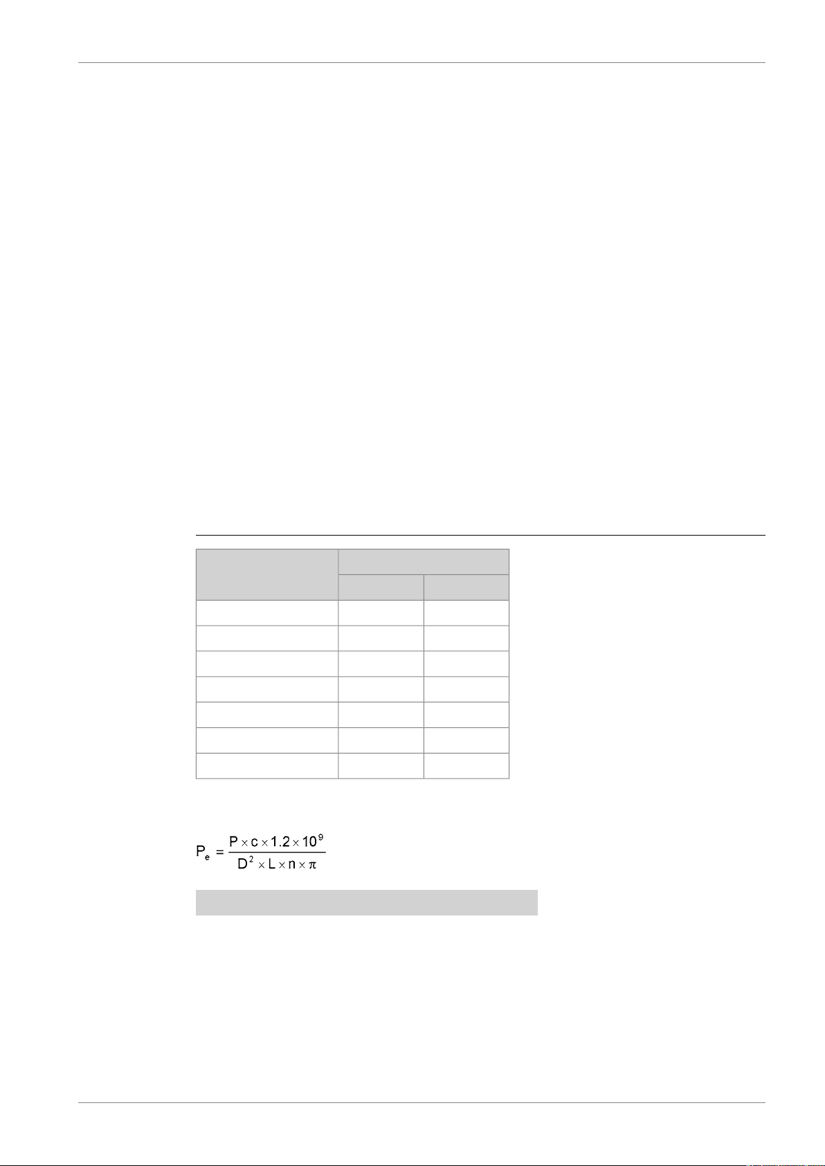
The mean effective pressure Pecan be calculated using the following formula:
where:
mean effective pressure [bar]Pe=
output per cylinder [kW]P =
engine speed [r/min]n =
cylinder diameter [mm]D =
length of piston stroke [mm]L =
operating cycle (4)c =
DBAD209883 1-1
Wärtsilä 46DF Product Guide1. Main Data and Outputs
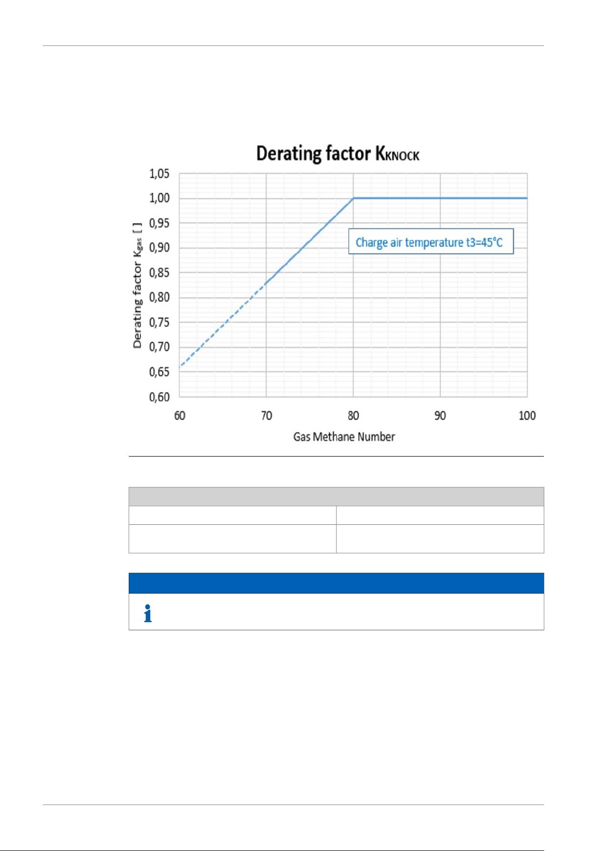
1.2 Output limitations in gas mode
1.2.1 Output limitations due to methane number
Fig 1-1 Output limitations due to methane number
Calculation Formulas for different compression ratios
if MN ≥ 80 and tbax ≤ 45 → KKNOCK = 1CR 12.7:1
if MN < 80 and/or tbax > 45 → KKNOCK = 1 -
0.017*(80 - MN) - (1 - (1 + 0.01*(45 - tbax)))
NOTE
In case of MN <80 and MN >70 derating factor could be 1%/1MN with a
penalization of efficiency.
1-2 DBAD209883

1. Main Data and OutputsWärtsilä 46DF Product Guide
NOTE
1) Gas fuel methane number refers to the gas quality at the engine inlet. This may
differ from the average gas quality in LNG tank.
2) Compensating a low methane number gas by lowering the charge air receiver
temperature below 45 °C is not allowed.
3) Compensating a higher charge air receiver temperature than 45 °C by a high
methane number gas is not allowed.
4) The dew point shall be calculated for the specific site conditions. The minimum
charge air receiver temperature shall be above the dew point, otherwise
condensation will occur in the charge air cooler.
5) The charge air receiver temperature is approximately 5 °C higher than the charge
air coolant temperature at rated load (CAC Team to be involved for LT water
temperature info).
6) Glycol usage in cooling water according to document DAAE062266.
7) Min. suction air temperature is 5 °C.
8) High suction air temperature gives a higher air temperature after compressor,
before the charge air cooler, and therefore a higher heat output from the 1-stage
of the charge air cooler, compared to low suction air temperature.
9) Temperatures given above are max. (continuous) operating temperature at site.
For suction air temperatures 40°C, please contact Product Engineering department.
10) The permissible pressure drop in the inlet pipe before the turbocharger is max.
1kPa.
11) The total sum of exhaust gas back pressure and air inlet pressure drop is not
allowed to be higher than 5 kPa.
DBAD209883 1-3
Wärtsilä 46DF Product Guide1. Main Data and Outputs
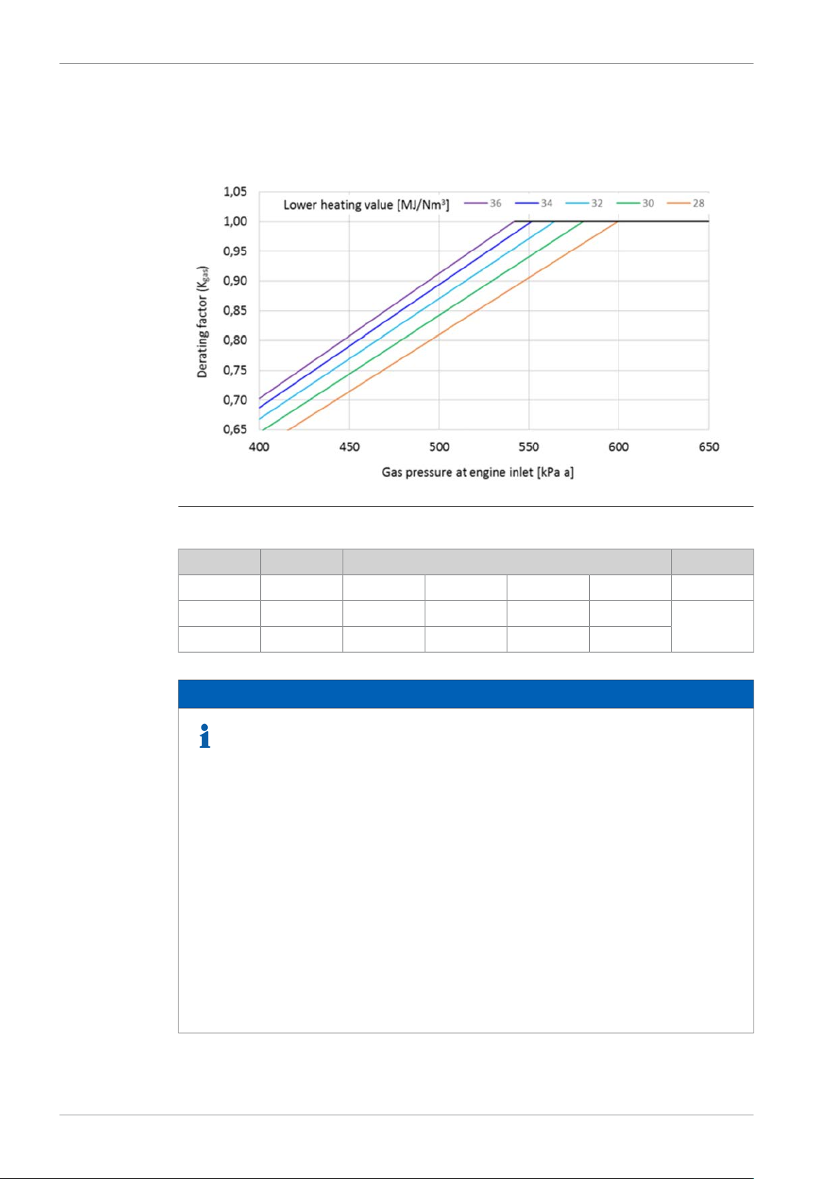
1.2.2 Output limitations due to gas feed pressure and lower heating value
Fig 1-2 Derating of output for gas feed pressure and LHV
MJ/Nm3
NOTE
1) Values given in m3 are valid at 0°C and 101.3 kPa.
2) The values for gas feed pressure are valid at the engine inlet i.e. after the gas
regulating unit.
3) Receiver pressure requirement is dependent on humidity. Receiver pressure
level influences on the required gas feed pressure. These values are valid for the
humidity up to 30g water/kg dry air.
4) Fuel gas feed pressure is not allowed to decrease from the level given for 36
MJ/Nm3 with LHV higher than 36 MJ/Nm3.
5) Gas fuel lower heating value refers to the gas quality at the engine inlet. This
may differ from the average gas quality in LNG tank.
2830323436KGAS
kPa a5995805645525421
3383263173093030,5
6) No compensation (uprating) of the engine output is allowed, neither for gas feed
pressure higher than required in the graph above nor lower heating value above
36 MJ/Nm3.
7) If the gas pressure is lower than required, a pressure booster unit can be installed
before the gas regulating unit to ensure adequate gas pressure. If pressure arise
is not possible the engine output has to be adjusted according to above.
1-4 DBAD209883

1.3 Reference conditions
The output is available within a range of ambient conditions and coolant temperatures specified
in the chapter Technical Data. The required fuel quality for maximum output is specified in the
section Fuel characteristics. For ambient conditions or fuel qualities outside the specification,
the output may have to be reduced.
The specific fuel consumption is stated in the chapter Technical Data. The statement applies
to engines operating in ambient conditions according to ISO 15550:2002 (E).
100 kPatotal barometric pressure
25 °Cair temperature
30 %relative humidity
25 °Ccharge air coolant temperature
Correction factors for the fuel oil consumption in other ambient conditions are given in standard
ISO 15550:2002 (E).
1.4 Operation in inclined position
1. Main Data and OutputsWärtsilä 46DF Product Guide
Max. inclination angles at which the engine will operate satisfactorily.
Permanent athwart ship inclinations
●
Temporary athwart ship inclinations
●
Permanent fore-and-aft inclinations
●
15.0°
22.5°
10.0°
DBAD209883 1-5
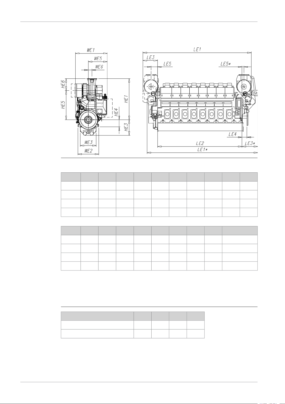
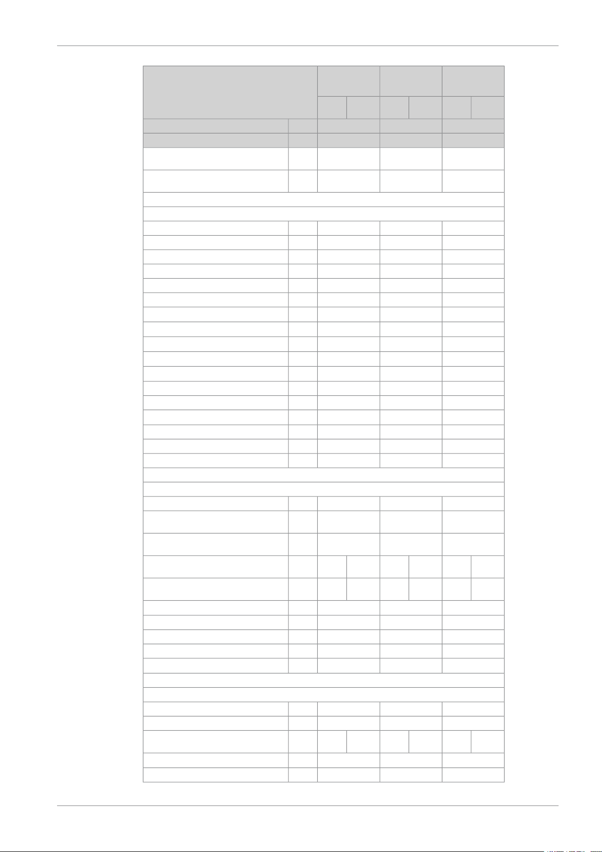
1.5 Dimensions and weights
Wärtsilä 46DF Product Guide1. Main Data and Outputs
Fig 1-3 In-line engines (DAAR038987)
HE3HE1LE5LE5*LE4LE3LE3*LE2LE1LE1*Engine
14303255699292460-15206170895386706L46DF
14303255699292460-15206990977396357L46DF
1430344565829246018831520781010593103108L46DF
1430344565829246018831520863011413111309L46DF
Weight [ton]WE6WE5WE3WE2WE1HE6HE5HE4Engine
102330178014801940318565026056506L46DF
118330178014801940318565026056507L46DF
130398178014801940318575526056508L46DF
146398178014801940318575526056509L46DF
* Turbocharger at driving end
All dimensions in mm. The weights are dry weights of rigidly mounted engines without flywheel.
Table 1-2 Additional weights [ton]:
9L46DF8L46DF7L46DF6L46DFItem
2222Flywheel
3.43.43.43.2Flexible mounting (without limiters)
1-6 DBAD209883
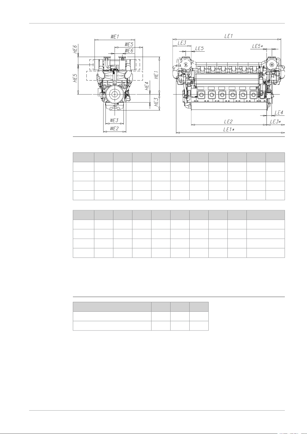
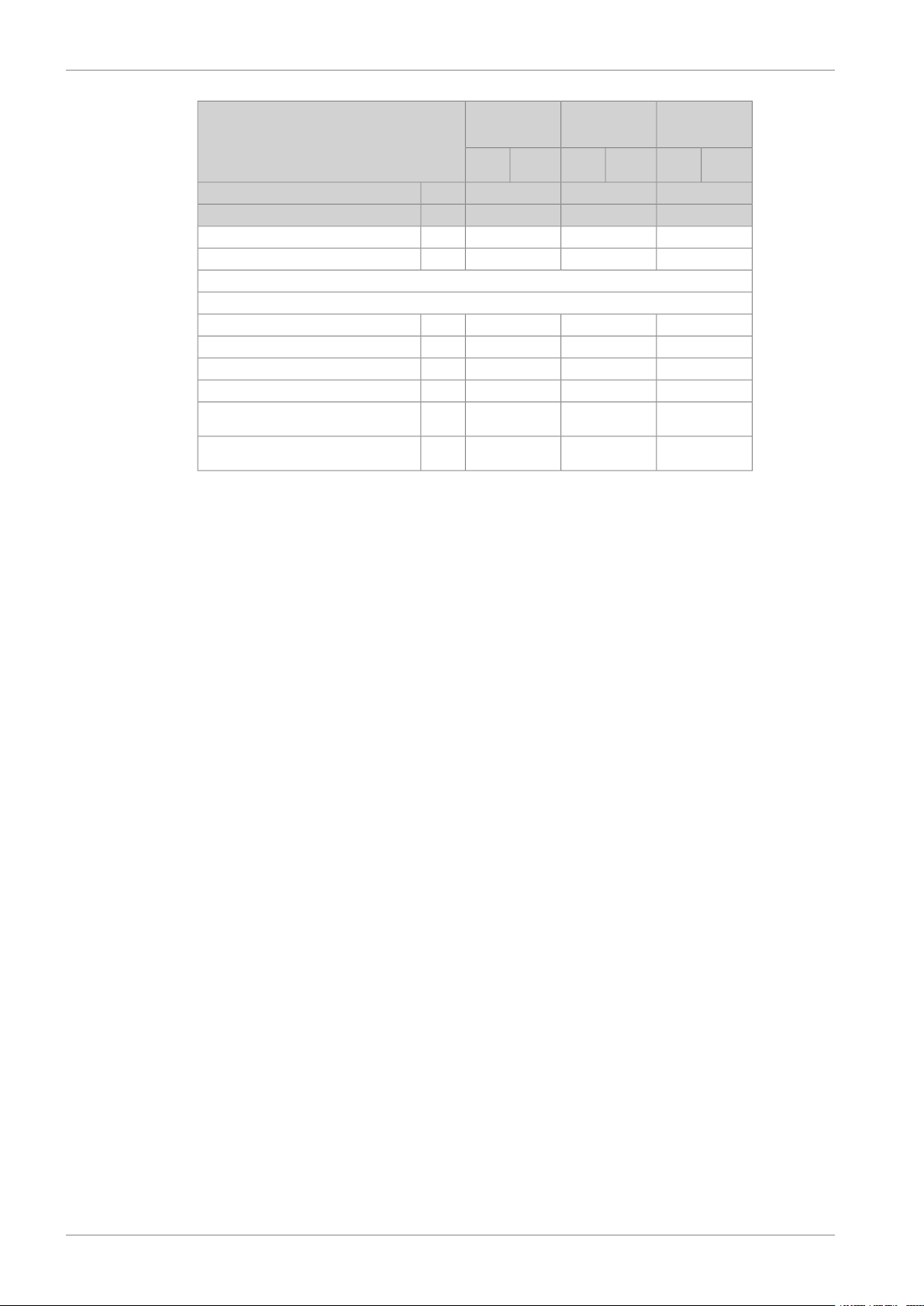
Fig 1-4 V-engines (DAAR038992)
1. Main Data and OutputsWärtsilä 46DF Product Guide
Engine
12V46DF*
12V46DF
14V46DF
16V46DF
Engine
12V46DF*
12V46DF
14V46DF
16V46DF
Weight [ton]WE6WE5WE3WE2WE1HE6HE5HE4
HE3HE1LE5LE5*LE4LE3LE3*LE2LE1LE1*
16203670-430460-19217600-11036
16203670684-4852043-760010375-
16203670684-4852043-865011425-
16203860689-4852347-970012687-
18478132251820229045556503020800
18478132251820229045556503020800
22378132251820229045556503020800
23585832251820229051747503110800
* Turbocharger at driving end
All dimensions in mm. The weights are dry weights of rigidly mounted engines without flywheel.
Table 1-3 Additional weights [ton]:
16V46DF14V46DF12V46DFItem
1.21.21.2Flywheel
10108Flexible mounting (without limiters)
DBAD209883 1-7

This page intentionally left blank

2. Operating Ranges
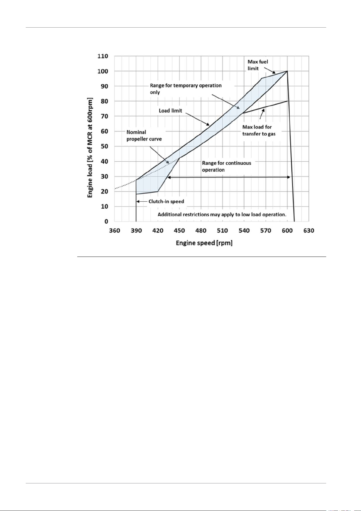
2.1 Engine operating range
Running below nominal speed the load must be limited according to the diagrams in this
chapter in order to maintain engine operating parameters within acceptable limits. Operation
in the shaded area is permitted only temporarily during transients. Minimum speed is indicated
in the diagram, but project specific limitations may apply.
2.1.1 Controllable pitch propellers
An automatic load control system is required to protect the engine from overload. The load
control reduces the propeller pitch automatically, when a pre-programmed load versus speed
curve (“engine limit curve”) is exceeded, overriding the combinator curve if necessary. Engine
load is determined from measured shaft power and actual engine speed. The shaft power
meter is supplied by Wärtsilä.
The propeller efficiency is highest at design pitch. It is common practice to dimension the
propeller so that the specified ship speed is attained with design pitch, nominal engine speed
and 85% output in the specified loading condition. The power demand from a possible shaft
generator or PTO must be taken into account. The 15% margin is a provision for weather
conditions and fouling of hull and propeller. An additional engine margin can be applied for
most economical operation of the engine, or to have reserve power.
2. Operating RangesWärtsilä 46DF Product Guide
The propulsion control must also include automatic limitation of the load increase rate.
Maximum loading rates can be found later in this chapter.
DBAD209883 2-1
Wärtsilä 46DF Product Guide2. Operating Ranges
Fig 2-1 Operating field for CP Propeller, 1145 kW/cyl, 600 rpm
Remarks: The maximum output may have to be reduced depending on gas properties and
gas pressure. The permissible output will in such case be reduced with same percentage at
all revolution speeds.
Restrictions for low load operation to be observed.
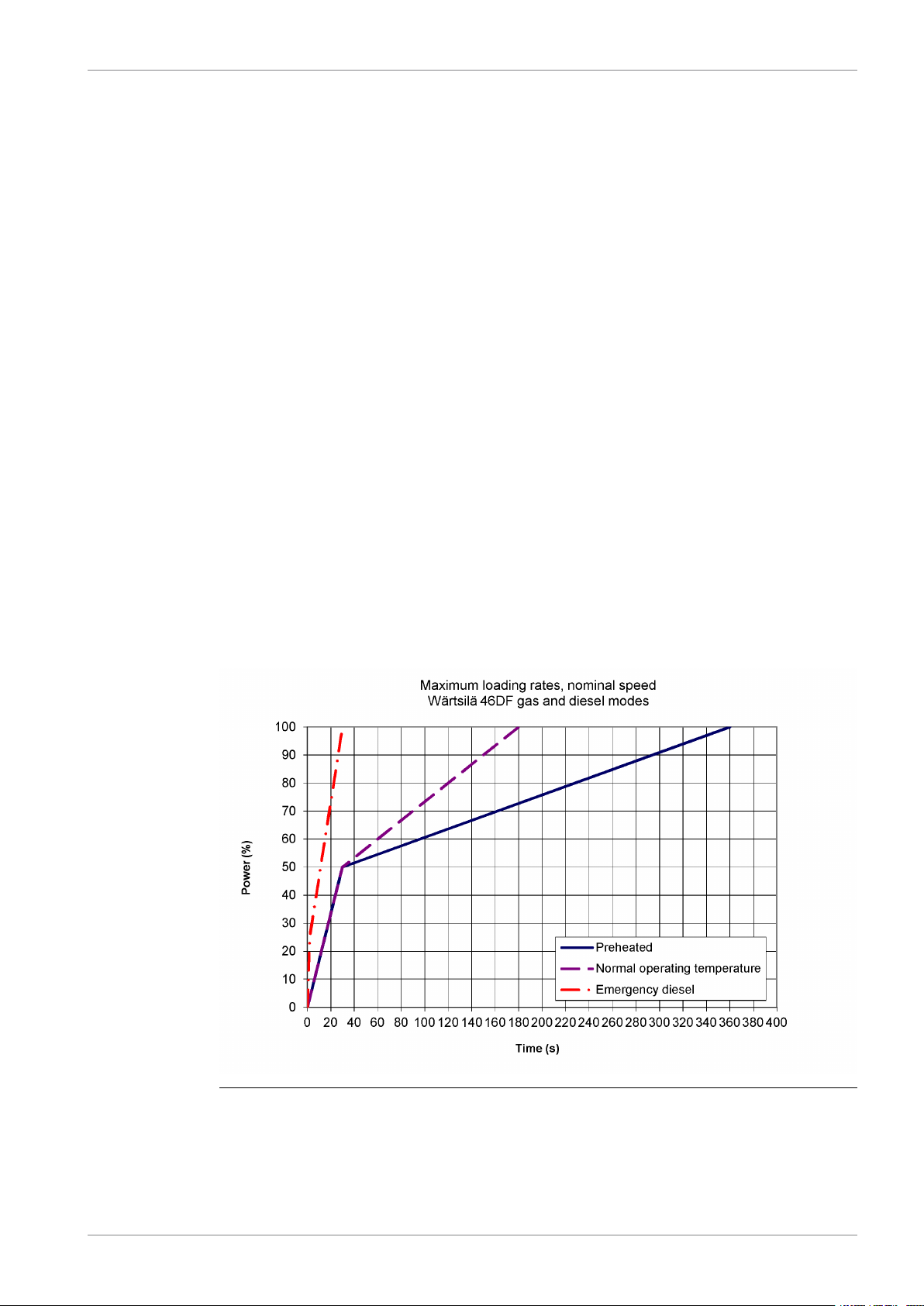
2.2 Loading capacity
Controlled load increase is essential for highly supercharged engines, because the turbocharger
needs time to accelerate before it can deliver the required amount of air. Sufficient time to
achieve even temperature distribution in engine components must also be ensured. Dual fuel
engines operating in gas mode require precise control of the air/fuel ratio, which makes
controlled load increase absolutely decisive for proper operation on gas fuel.
The loading ramp “preheated” (see figures) can be used as the default loading rate for both
diesel and gas mode. If the control system has only one load increase ramp, then the ramp
for a preheated engine must be used. The HT-water temperature in a preheated engine must
be at least 70ºC, and the lubricating oil temperature at least 40ºC.
The loading ramp “Normal operating temperature” can be taken into use when the engine has
been operating above 30% load for 6 minutes (or the cooling water temperature after cylinders
is min. 85ºC). All engines respond equally to a change in propulsion power (or total load), also
when a recently connected engine is still uploading to even load sharing with parallel engines.
A recently connected generator shall therefore not be taken into account as “available power”
until after 6 minutes, or alternatively the available power from this generator is ramped up to
100% during 10 minutes. If the control system has only one load increase ramp, then the ramp
for a preheated engine is to be used.
2-2 DBAD209883
2. Operating RangesWärtsilä 46DF Product Guide
Fast load changes must be avoided during transfer from diesel to gas mode.
The “emergency” loading ramp in diesel mode can be used in critical situations, e.g. when
recovering from a fault condition to regain sufficient propulsion and steering as fast as possible.
The emergency ramp can be activated manually or according to some predefined condition,
and there shall be a visible alarm indicating that emergency loading is activated.
In applications with highly cyclic load, e.g. dynamic positioning and manoeuvring, maximum
loading and unloading capacity in gas mode (see figure 2-3) can be used in operating modes
that requires fast response. Other operating modes should have slower loading rates. If the
request is to use this curve intensively a special agreement/contract with end customer is
needed.
Maximum possible loading and unloading can also be required in other special applications.
The engine control does not limit the loading rate in gas mode (it only acts on deviation from
reference speed). If the loading rate is faster than the capacity in gas mode, the engine trips
to diesel.
Electric generators must be capable of 10% overload. The maximum engine output is 110%
in diesel mode and 100% in gas mode. Trip to diesel mode takes place automatically in case
of overload. Lower than specified methane number may result in automatic transfer to diesel
when operating close to 100% output. Load taking ability is also influenced from low methane
number. Expected variations in gas fuel quality must be taken into account to ensure that gas
operation can be maintained in normal operation.
2.2.1 Mechanical propulsion, controllable pitch propeller (CPP)
For successive loading rates and max ramp in variable speed, please contact Wartsila to have
further informations.
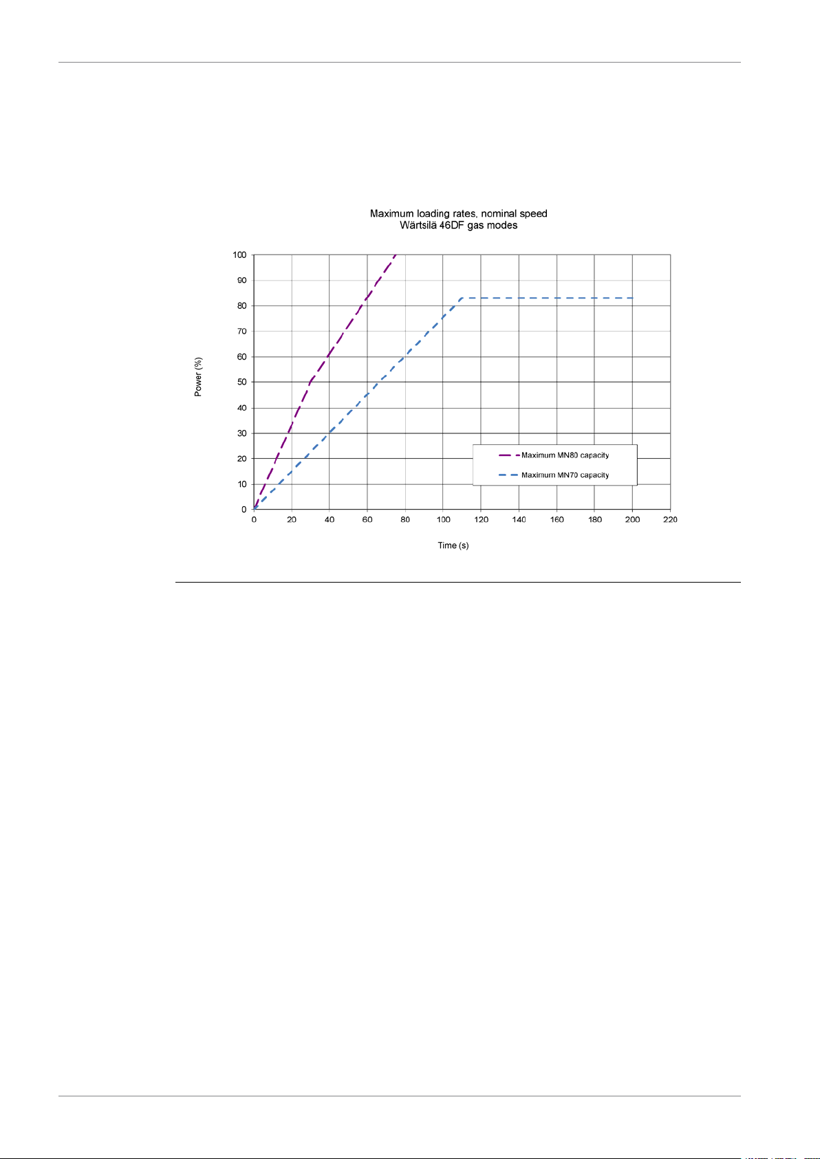
2.2.2 Constant speed application
Fig 2-2 Successive Loading & Unloading
The loading rates in gas mode in the diagrams above are to be applied when the gas Methane
Number is ≥ 80. For MN below 80, please contact Wartsila for further information.
DBAD209883 2-3
Wärtsilä 46DF Product Guide2. Operating Ranges
Unloading:
In normal operation the load should not be reduced from high load to low load (much) faster
than the load is increased. Crash stop can be recognised with a large lever movement form
ahead to astern within some seconds, which overrides normal load reduction. In the
manoeuvring range, typically below 50% load, the load can be reduced without rate limitation.
Fig 2-3 Maximum Loading and Unloading capacity in gas
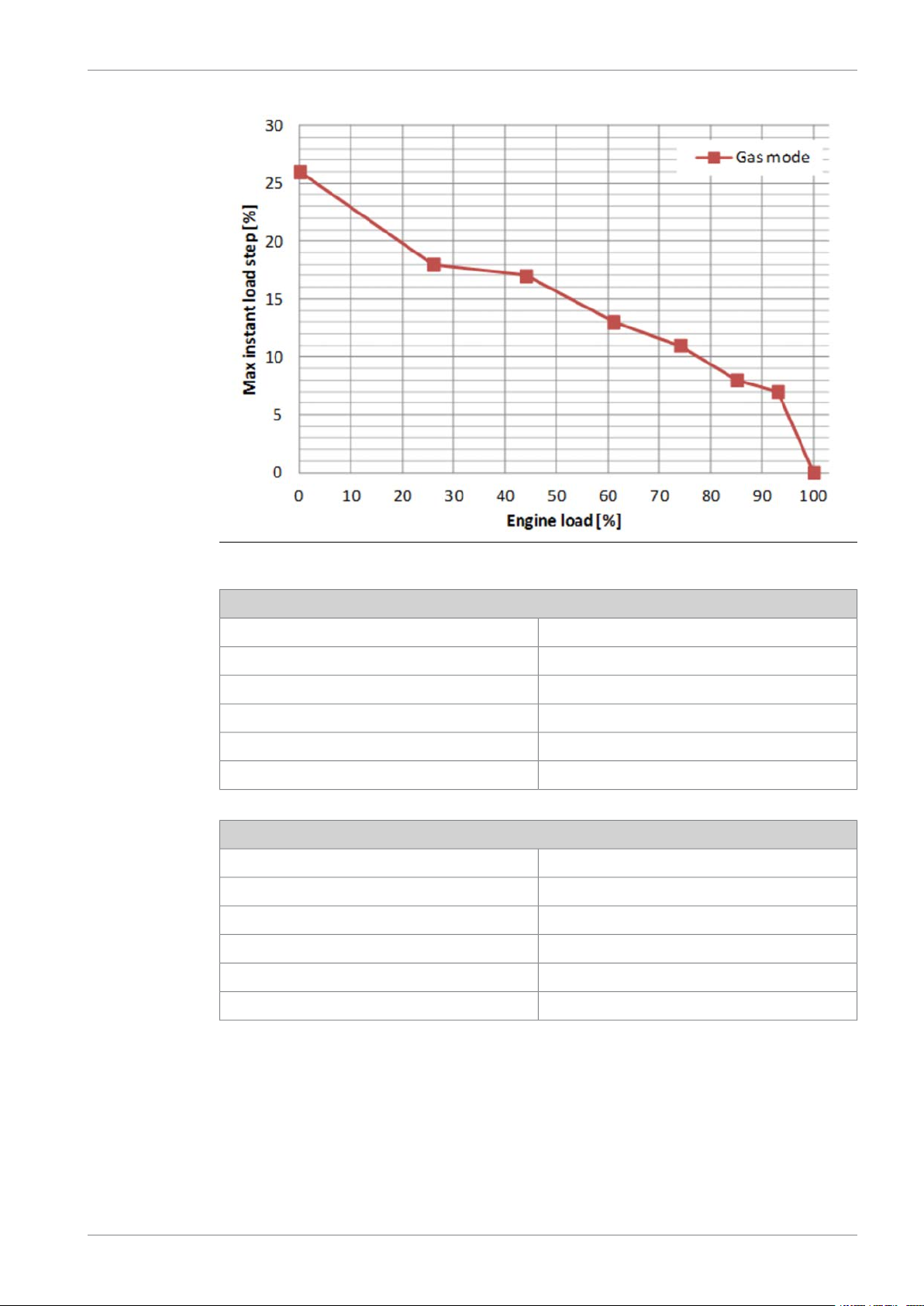
2.2.2.1 Maximum instant load steps
The electrical system must be designed so that tripping of breakers can be safely handled.
This requires that the engines are protected from load steps exceeding their maximum load
acceptance capability. If fast load shedding is complicated to implement or undesired, the
instant load step capacity can be increased with a fast acting signal that requests transfer to
diesel mode.
2-4 DBAD209883
2. Operating RangesWärtsilä 46DF Product Guide
Fig 2-4 Maximum permissible load step in gas mode
Gas - Mode
Stepwise Load ReductionInstant Load Application
•Maximum load step according to figure above•Maximum load step according to figure above
•Steady-state frequency band ≤ 1.5 %•Steady-state frequency band ≤ 1.5 %
•Maximum speed increase 10 %•Maximum speed drop 10 %
•Recovery time ≤ 10 s•Recovery time ≤ 10 s
•Time between load steps ≥ 20 s ²)•Time between load steps ≥ 20 s ¹)
Diesel Mode
Stepwise Load ReductionInstant Load Application
•Instant load step 100% - 50% - 0%•Instant load step: 0% - 33% - 56% - 77% - 100%
•Steady-state frequency band ≤ 1.0 %•Steady-state frequency band ≤ 1.0 %
•Maximum speed increase 10 %•Maximum speed drop 10 %
•Recovery time ≤ 10 s•Recovery time ≤ 10 s
•Time between load steps ≥ 5 s )
DBAD209883 2-5

NOTE
1) In case instant load steps are applied on top of Successive loading (ramp), the
minimum time between load steps is 45 s and the maximum load application rate
between steps is 10% / 60 s. However the maximum loading limit may not be
exceeded.
2) For exceptional situations which require fast unloading (e.g. propulsion crash
stop manoeuvring) it is recommended that the engine control system be configured
for automatic transfer to diesel-mode for fastest possible unloading.
Note that the recovery time is longer than the normal class requirement (5 s). The
steady-state frequency band in gas mode also exceeds the normal class
requirement (1.0 %).
2.3 Operation at low load and idling
Absolute idling (declutched main engine, disconnected generator):
● Maximum 10 minutes if the engine is to be stopped after the idling. 3-5 minutes idling
before stop is recommended.
● Maximum 8 hours if the engine is to be loaded after the idling.
Wärtsilä 46DF Product Guide2. Operating Ranges
● After a gas start it is recommended to synchronize and load the engine within 1 minute
after nominal speed is reached.
Operation below 20 % load on HFO or below 10 % load on MDF or gas:
● Maximum 100 hours continuous operation. At intervals of 100 operating hours the engine
must be loaded to min. 70% of the rated output for 1 hour.
● If operated longer than 30h in liquid fuel mode, the engine must be loaded to minimum
70% of rated output for 1 hour before transfer to gas.
● Before operating below 10% in gas mode the engine must run above 10% load for at least
10 minutes. It is however acceptable to change to gas mode directly after the engine has
reached nominal speed after the engine has started, provided that the charge air temperature
is above 55°C.
Operation above 20 % load on HFO or above 10 % load on MDF or gas:
● No restrictions.
Operation at low load and idling with SCR (NOR)
LFO/MGO
●
Idling Max continuous operation time: 2h; Requirements before further operation at low
load can be continues: above 25% load for 1 h
●
Below 10%MCR Max continuous operation time: 6h; Requirements before further operation
at low load can be continues: above 70% load for 1 h or above 50% load for 2 h
●
Below 25%MCR Max continuous operation time: 24h; Requirements before further
operation at low load can be continues: above 70% load for 1 h or above 50% load for 2
h
Gas (MN≥=70)
●
Idling Max continuous operation time: 5 min; Requirements before further operation at low
load can be continues: above 20% load for 30 min or change to back-up fuel (trip to diesel
is also included as an automatic back-up feature)
●
Below 5% MCR Max continuous operation time: 10 min; Requirements before further
operation at low load can be continues: above 20% load for 30 min or change to back-up
fuel (trip to diesel is also included as an automatic back-up feature)
2-6 DBAD209883

2. Operating RangesWärtsilä 46DF Product Guide
●
Between 5% and 10% MCR Max continuous operation time: 15 min; Requirements before
further operation at low load can be continues: above 20% load for 30 min or change to
back-up fuel (trip to diesel is also included as an automatic back-up feature)
●
Above 10% MCR No restrictions
Gas (MN<70)
●
Idling Max continuous operation time: 3 min; Requirements before further operation at low
load can be continues: above 20% load for 30 min or change to back-up fuel (trip to diesel
is also included as an automatic back-up feature)
●
Below 10% MCR Max continuous operation time: 5 min; Requirements before further
operation at low load can be continues: above 20% load for 30 min or change to back-up
fuel (trip to diesel is also included as an automatic back-up feature)
●
Above 10% MCR No restrictions
NOTE
Typically, less strict requirements for the operation can be set based on a detailed
analysis of project specific conditions such as operational profile, fuel composition
and engine type and tuning.
In low load gas operation the oxidation of unburned hydrocarbons on the catalyst
elements can increase the temperature above the limit for catalyst elements and/or
the exhaust gas system. The extent of the temperature increase depends on
combustion parameters, operational profile, ambient conditions and especially on
the gas compositions.
The solution for allowing trouble free operation in low load gas operation includes
the following:
1) Use of dilution air to provide cooling in low load operation.
2) Recommendations for duration of low load operation. These recommendations
will in normal conditions ensure that the temperature will remain in the allowed
area.
3) SCR temperature monitoring will trigger a transfer to liquid fuel operation to
protect the SCR in situations with increased temperatures.
DBAD209883 2-7
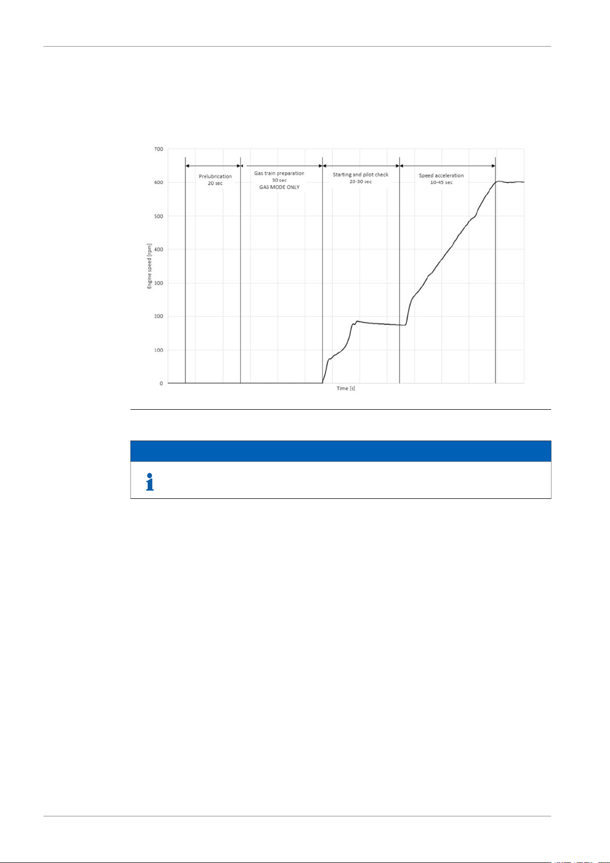
2.3.1 Nominal Start-up time
2.3.1.1 For preheated engine
Wärtsilä 46DF Product Guide2. Operating Ranges
Fig 2-5 Nominal start-up time
Continuous prelubrication of the engine can be done when the engine is in stop
mode if shorter start-up time is required.
2.4 Low air temperature
The minimum inlet air temperature of 5°C applies, when the inlet air is taken from the engine
room.
Engines can run in colder conditions at high loads (suction air lower than 5°C) provided that
special provisions are considered to prevent too low HT-water temperature and T/C surge.
For start, idling and low load operations (Ch 2.3), suction air temperature shall be maintained
at 5°C.
If necessary, the preheating arrangement can be designed to heat the running engine (capacity
to be checked).
For further guidelines, see chapter Combustion air system design.
NOTE
2-8 DBAD209883
3. Technical Data
3.1 Introduction
This chapter contains technical data of the engine (heat balance, flows, pressures etc.) for
design of ancillary systems. Further design criteria for external equipment and system layouts
are presented in the respective chapter.
Separate data is given for engines driving propellers “ME” and engines driving generators
“DE”.
3.2 Wärtsilä 6L46DF
3. Technical DataWärtsilä 46DF Product Guide
Wärtsilä 6L46DF
Combustion air system (Note 1)
Exhaust gas system (Note 2)
(TE 517)
(TE 517)
(TE 517)
(TE 517)
°CTemperature after turbocharger at 50% load
ME
CPP Variable
Speed
Diesel
Gas
mode
-
mode
298336
ME
CPP Constant
Speed
Diesel
Gas
mode
mode
297450
-
DE
DE Constant
Speed
Diesel
Gas
mode
114511451145kWCylinder output
600600600rpmEngine speed
687068706870kWEngine output
2.382.382.38MPaMean effective pressure
454545°CTemperature at turbocharger intake, max.
-
444kPaBackpressure, max.
mode
12.311.112.311.112.311.1kg/sFlow at 100% load
504550455045°CTemperature after air cooler, nom. (TE 601)
13.411.013.711.013.711.0kg/sFlow at 100% load
11.58.411.68.410.78.5kg/sFlow at 75% load
314365301367301367°CTemperature afterturbocharger at 100% load
305390292392294364°CTemperature after turbocharger at 85% load
304407292409304346°CTemperature after turbocharger at 75% load
306449
899847897849897849mmCalculated exhaust diameter for 35 m/s
Heat balance at 100% load (Note 3)
106884010808401080840kWJacket water, HT-circuit
187813862016138620161386kWCharge air, HT-circuit
858636882636882636kWCharge air, LT-circuit
762408768408768408kWLubricating oil, LT-circuit
204192204192204192kWRadiation
Fuel consumption (Note 4)
-7390-7410-7410kJ/kWhBSEC total at 100% load
-7530-7540-7420kJ/kWhBSEC total at at 85% load
DBAD209883 3-1

Wärtsilä 46DF Product Guide3. Technical Data
Wärtsilä 6L46DF
ME
CPP Variable
Speed
Diesel
Gas
mode
mode
ME
CPP Constant
Speed
Diesel
Gas
mode
mode
DE
DE Constant
Speed
Gas
mode
114511451145kWCylinder output
600600600rpmEngine speed
Diesel
mode
-7660-7680-7470kJ/kWhBSEC total at at 75% load
-8210-8230-7710kJ/kWhBSEC total at at 50% load
-7350-7365-7365kJ/kWhBSEC gas fuel at 100% load
-7485-7501-7373kJ/kWhBSEC gas fuel at 85% load
-7594-7611-7422kJ/kWhBSEC gas fuel at 75% load
-8071-8091-7620kJ/kWhBSEC gas fuel at 50% load
0.61.00.61.00.61.0g/kWhPilot fuel consumption at 100% load
0.81.20.81.20.71.2g/kWhPilot fuel consumption at 85% load
0.81.30.81.30.71.3g/kWhPilot fuel consumption at 75% load
1.33.51.33.51.02.0g/kWhPilot fuel consumption at 50% load
185.3-186.3-186.3-g/kWhSFOC at 100% load - LFO
181.0-181.0-178.2-g/kWhSFOC at 85 % load - LFO
193.0-193.0-189.1-g/kWhSFOC at 75% load - LFO
198.5-198.5-192.3-g/kWhSFOC at 50% load - LFO
185.3-186.3-186.3-g/kWhSFOC at 100% load - HFO
180.1-180.1-177.2-g/kWhSFOC at 85% load - HFO
195-195-191-g/kWhSFOC at 75% load - HFO
203-203-197-g/kWhSFOC at 50% load - HFO
Fuel gas system (Note 5)
100% load
Fuel oil system
85% load
idle speed (check value)
101)
load
load
engine
-600...800-600...800-600...800kPa (a)Gas pressure at engine inlet, min (PT901) at
-120-120-120kPa (a)Pressure drop over the Gas Valve unit, min
-0...60-0...60-0...60°CGas temperature at engine inlet
900...950900...950900...950kPaPressure before injection pumps (PT101) at
1000...10501000...10501000...1050kPaPressure before injection pumps (PT 101) at
5.1...6.05.1...6.05.1...6.0m3/hFuel oil flow to engine, range
16...24-16...24-16...24-cStHFO viscosity before the engine
140-140-140-°CMax. HFO temperature beforeengine(TE101)
2.02.02.0cStMDF viscosity, min.
404040°CMax. MDF temperature before engine (TE
4.5-4.5-4.5-kg/hLeak fuel quantity (HFO), clean fuel at 100%
22.512.022.512.022.512.0kg/hLeak fuel quantity (MDF), clean fuel at 100%
2...112...112...11cStPilot fuel (MDF) viscosity before the engine
550...750550...750550...750kPa(g)Pilot fuel pressure at engine inlet (PT 112)
150150150kPa(g)Pilot fuel outlet pressure, max
410410410kg/hPilot fuel return flow at 100% load
750...1500750...1500750...1500l/hExternal Pilot fuel feed pump, 1 feeder per
3-2 DBAD209883
3. Technical DataWärtsilä 46DF Product Guide
Wärtsilä 6L46DF
multiple engines
(TE112)
Lubricating oil system
Oil volume in separate system oil tank
Crankcase volume
l/hExternal Pilot fuel feed pump, 1 feeder per
3
3
ME
CPP Variable
Speed
Diesel
Gas
mode
mode
=(850...1500) x
numb_of_eng
ME
CPP Constant
Speed
Diesel
Gas
mode
mode
=(850...1500) x
numb_of_eng
DE
DE Constant
Speed
Diesel
Gas
mode
mode
114511451145kWCylinder output
600600600rpmEngine speed
=(850...1500) x
numb_of_eng
5...505...505...50°CPilot line, temperature before pilot pumps
500500500kPaPressure before bearings, nom. (PT 201)
800800800kPaPressure after pump, max.
404040kPaSuction ability, including pipe loss, max.
808080kPaPrelubricating pressure, nom. (PT 201)
55...5855...5855...58°CTemperature before bearings, nom. (TE 201)
757575°CTemperature after engine, approx.
175175191m3/hPump capacity (main), engine driven
158158158m3/hPump capacity (main), electrically driven
130130130m3/hOil flow through engine
35.0 / 35.035.0 / 35.035.0 / 35.0m3/hPrelubricating pump capacity (50/60Hz)
131313m
0.50.50.5g/kWhOil consumption at 100% load, approx.
280028002800l/minCrankcase ventilation flow rate at full load
17.817.817.8m
0.50.50.5kPaCrankcase ventilation backpressure, max.
8.5...9.58.5...9.58.5...9.5lOil volume in turning device
1.71.71.7lOil volume in speed governor
HT cooling water system
at 100% nom.
pass pipe return to HT pump suction)
100% nom.
at 100% nom.
Water volume in engine
LT cooling water system
at 100% nom.
250 + static250 + static250 + statickPaPressure at engine, after pump, nom.(PT 401)
530530530kPaPressure at engine, after pump, max. (PT401)
747474°CTemperature to HT suction, max (before by-
727572757275°CTemperature before cylinders (TE 401) at
979397939793°CTemperature after charge air cooler (TE432)
150150150m3/hCapacity of engine driven pump, nom.
100100100kPaPressure drop over jacket, total
100100100kPaPressure drop in external system, max.
70...15070...15070...150kPaPressure from expansion tank
3
1.01.01.0m
250+ static250+ static250+ statickPaPressure at engine,after pump, nom. (PT 471)
530530530kPaPressure at engine, after pump, max. (PT471)
423842384238°CTemperature before charge air cooler (TE471)
150150150m3/hCapacity of engine driven pump, nom.
505050kPaPressure drop over charge air cooler
DBAD209883 3-3
Wärtsilä 46DF Product Guide3. Technical Data
Wärtsilä 6L46DF
Starting air system (Note 6)
Consumption per start at 20 °C (successful
start)
Consumption per start at 20 °C (with
slowturn)
Notes:
At ISO 15550 conditions (ambient air temperature 25°C) and 100% load. Flow tolerance 8%.Note 1
At ISO 15550 conditions (ambient air temperature 25°C). Flow tolerance 8% and temperature tolerance 15°C.
Note 2
Available maxbackpressure is 6 KpA;in this condition all consumption and HB value haveto be evaluated. Please contact
Wärtsilä to have further informations.
At ISO 15550 conditions (ambient air temperature 25°C ) and 100% load. Tolerance for cooling waterheat 10%, tolerance
Note 3
for radiation heat 30%. Fouling factors and a margin to be taken into account when dimensioning heat exchangers.
According to ISO 15550, lower calorific value 42700 kJ/kg, with engine driven pumps (two cooling water + one lubricating
Note 4
oil pumps). Tolerance 5%. The fuel consumption at 85 % load is guaranteed and the values at other loads are given for
indication only.
Consumption values in constant speed are valid for D2/E2 IMO cycles.
*If SCR (with a max sulphur content of 0.5%m/m) is applied SFOC consumption values @ 85% may vary in this way:
SFOC(85%) + 0.5g/kWh + (335- (Temperature after turbocharger at 85%))*0.04 g/kWh. Please contact Wärtsilä to have
further informations.
Fuel gas pressure given at LHV ≥ 36MJ/m³N. Required fuel gas pressure depends on fuel gas LHV and need to be increased
Note 5
for lower LHV's. Pressure drop in external fuel gas system to be considered. See chapter Fuel system for further information.
At manual starting the consumption may be 2...3 times lower.Note 6
mode
3
3
ME
CPP Variable
Speed
Diesel
Gas
mode
ME
CPP Constant
Speed
Diesel
Gas
mode
mode
DE
DE Constant
Speed
Gas
mode
114511451145kWCylinder output
600600600rpmEngine speed
135135135kPaPressure drop in external system, max.
70...15070...15070...150kPaPressure from expansion tank
300030003000kPaPressure, nom. (PT 301)
150015001500kPaPressure at engine during start, min. (20 °C)
300030003000kPaPressure, max. (PT 301)
180018001800kPaLow pressure limit in starting air vessel
6.06.06.0Nm
7.07.07.0Nm
Diesel
mode
ME = Engine driving propeller, variable speed
DE = Diesel-Electric engine driving generator
Subject to revision without notice.
3-4 DBAD209883

3.3 Wärtsilä 7L46DF
3. Technical DataWärtsilä 46DF Product Guide
Wärtsilä 7L46DF
Combustion air system (Note 1)
Exhaust gas system (Note 2)
(TE 517)
(TE 517)
(TE 517)
(TE 517)
ME
CPP Variable
Speed
Diesel
Gas
mode
mode
ME
CPP Constant
Speed
Diesel
Gas
mode
mode
DE
DE Constant
Speed
Diesel
Gas
mode
114511451145kWCylinder output
600600600rpmEngine speed
801580158015kWEngine output
2.382.382.38MPaMean effective pressure
454545°CTemperature at turbocharger intake, max.
444kPaBackpressure, max.
mode
14.312.914.312.914.312.9kg/sFlow at 100% load
504550455045°CTemperature after air cooler, nom. (TE 601)
15.712.816.012.816.012.8kg/sFlow at 100% load
13.49.813.69.812.59.9kg/sFlow at 75% load
314365301367301367°CTemperature afterturbocharger at 100% load
305390292392294364°CTemperature after turbocharger at 85% load
304407292409304346°CTemperature after turbocharger at 75% load
306449297450298336°CTemperature after turbocharger at 50% load
971915969917969917mmCalculated exhaust diameter for 35 m/s
Heat balance at 100% load (Note 3)
Fuel consumption (Note 4)
124698012609801260980kWJacket water, HT-circuit
219116172352161723521617kWCharge air, HT-circuit
100174210297421029742kWCharge air, LT-circuit
889476896476896476kWLubricating oil, LT-circuit
238224238224238224kWRadiation
-7390-7410-7410kJ/kWhBSEC total at 100% load
-7530-7540-7420kJ/kWhBSEC total at 85% load
-7660-7680-7470kJ/kWhBSEC total at 75% load
-8210-8230-7710kJ/kWhBSEC total at 50% load
-7350-7365-7365kJ/kWhBSEC gas fuel at 100% load
-7485-7501-7373kJ/kWhBSEC gas fuel at 85% load
-7594-7611-7422kJ/kWhBSEC gas fuel at 75% load
-8071-8091-7620kJ/kWhBSEC gas fuel at 50% load
0.61.00.61.00.61.0g/kWhPilot fuel consumption at 100% load
0.81.20.81.20.71.2g/kWhPilot fuel consumption at 85% load
0.81.30.81.30.71.3g/kWhPilot fuel consumption at 75% load
1.33.51.33.51.02.0g/kWhPilot fuel consumption at 50% load
185.3-186.3-186.3-g/kWhSFOC at 100% load - LFO
181.0-181.0-178.2-g/kWhSFOC at 85% load - LFO
DBAD209883 3-5

Wärtsilä 46DF Product Guide3. Technical Data
Wärtsilä 7L46DF
Fuel gas system (Note 5)
100% load
Fuel oil system
85% load - HFO
idle speed (check value)
101)
load
load
engine
multiple engines
(TE112)
l/hExternal Pilot fuel feed pump, 1 feeder per
ME
CPP Variable
Speed
Diesel
Gas
mode
mode
=(850...1500) x
numb_of_eng
ME
CPP Constant
Speed
Diesel
Gas
mode
mode
=(850...1500) x
numb_of_eng
DE
DE Constant
Speed
Diesel
Gas
mode
mode
114511451145kWCylinder output
600600600rpmEngine speed
193.0-193.0-189.1-g/kWhSFOC at 75% load - LFO
198.5-198.5-192.3-g/kWhSFOC at 50% load - LFO
185.3-186.3-186.3-g/kWhSFOC at 100% load - HFO
180.1-180.1-177.2-g/kWhSFOC at 85% load - HFO
195-195-191-g/kWhSFOC at 75% load - HFO
203-203-197-g/kWhSFOC at 50% load - HFO
900...950900...950900...950kPaPressure before injection pumps (PT101) at
1000...10501000...10501000...1050kPaPressure before injection pumps (PT 101) at
5.9...7.05.9...7.05.9...7.0m3/hFuel oil flow to engine, range
16...24-16...24-16...24-cStHFO viscosity before the engine
140-140-140-°CMax. HFO temperature before engine (TE 101)
2.02.02.0cStMDF viscosity, min.
404040°CMax. MDF temperature before engine (TE
5.2-5.2-5.2-kg/hLeak fuel quantity (HFO), clean fuel at 100%
26.514.026.514.026.514.0kg/hLeak fuel quantity (MDF), clean fuel at 100%
2...112...112...11cStPilot fuel (MDF) viscosity before the engine
550...750550...750550...750kPa(g)Pilot fuel pressure at engine inlet (PT 112)
150150150kPa(g)Pilot fuel outlet pressure, max
420420420kg/hPilot fuel return flow at 100% load
750...1500750...1500750...1500l/hExternal Pilot fuel feed pump, 1 feeder per
=(850...1500) x
numb_of_eng
5...505...505...50°CPilot line, temperature before pilot pumps
-600...800-600...800-600...800kPa (a)Gas pressure at engine inlet, min (PT901) at
-120-120-120kPa (a)Pressure drop over the Gas Valve unit, min
-0...60-0...60-0...60°CGas temperature at engine inlet
Lubricating oil system
500500500kPaPressure before bearings, nom. (PT 201)
800800800kPaPressure after pump, max.
404040kPaSuction ability, including pipe loss, max.
808080kPaPriming pressure, nom. (PT 201)
55...5855...5855...58°CTemperature before bearings, nom. (TE 201)
757575°CTemperature after engine, approx.
191191207m3/hPump capacity (main), engine driven
179179179m3/hPump capacity (main), electrically driven
3-6 DBAD209883
 Loading...