

WÄRTSILÄ 34DF Product Manual
WÄRTSILÄ 34DF
PRODUCT GUIDE

© Copyright by WÄRTSILÄ FINLAND Oy
All rights reserved. No part of this booklet may be reproduced or copied in any form or by any means (electronic,
mechanical, graphic, photocopying, recording, taping or other information retrieval systems) without the prior written
permission of the copyright owner.
THIS PUBLICATION IS DESIGNED TO PROVIDE AN ACCURATE AND AUTHORITATIVE INFORMATION WITH
REGARD TO THE SUBJECT-MATTER COVERED AS WAS AVAILABLE AT THE TIME OF PRINTING. HOWEVER,THE
PUBLICATION DEALS WITH COMPLICATED TECHNICAL MATTERS SUITED ONLY FOR SPECIALISTS IN THE
AREA, AND THE DESIGN OF THE SUBJECT-PRODUCTS IS SUBJECT TO REGULAR IMPROVEMENTS,
MODIFICATIONS AND CHANGES. CONSEQUENTLY, THE PUBLISHER AND COPYRIGHT OWNER OF THIS
PUBLICATION CAN NOT ACCEPT ANY RESPONSIBILITY OR LIABILITY FOR ANY EVENTUAL ERRORS OR
OMISSIONS IN THIS BOOKLET OR FOR DISCREPANCIES ARISING FROM THE FEATURES OF ANY ACTUAL ITEM
IN THE RESPECTIVE PRODUCT BEING DIFFERENT FROM THOSE SHOWN IN THIS PUBLICATION. THE PUBLISHER
AND COPYRIGHT OWNER SHALL UNDER NO CIRCUMSTANCES BE HELD LIABLE FOR ANY FINANCIAL
CONSEQUENTIAL DAMAGES OR OTHER LOSS, OR ANY OTHER DAMAGE OR INJURY, SUFFERED BY ANY
PARTY MAKING USE OF THIS PUBLICATION OR THE INFORMATION CONTAINED HEREIN.

Introduction
This Product Guide provides data and system proposals for the early design phase of marine
engine installations. For contracted projects specific instructions for planning the installation
are always delivered. Any data and information herein is subject to revision without notice.
This 2/2016 issue replaces all previous issues of the Wärtsilä 34DF Product Guides.
UpdatesPublishedIssue
Technical data updated23.09.20162/2016
Technical data updated. Cylinder output 435/450 kW removed.15.09.20161/2016
Process drawings and technical data updated17.12.20153/2015
Process drawings updated. Fuel sharing mode and low load optimization
added.
13.11.20152/2015
Updates throughout the product guide27.02.20151/2015
September 2016
Wärtsilä, Marine Solutions
Wärtsilä 34DF Product Guide - a16 - 23 September 2016 iii
IntroductionWärtsilä 34DF Product Guide

Table of contents
1-11. Main Data and Outputs .......................................................................................................................
1-11.1 Technical main data .....................................................................................................................
1-11.2 Maximum continuous output .......................................................................................................
1-21.3 Output limitations in gas mode ....................................................................................................
1-51.4 Reference conditions ...................................................................................................................
1-51.5 Operation in inclined position .....................................................................................................
1-61.6 Principal dimensions and weights ...............................................................................................
2-12. Operating Ranges ................................................................................................................................
2-12.1 Engine operating range ...............................................................................................................
2-22.2 Loading capacity .........................................................................................................................
2-52.3 Operation at low load and idling ..................................................................................................
2-52.4 Low air temperature ....................................................................................................................
3-13. Technical Data ......................................................................................................................................
3-13.1 Wärtsilä 6L34DF ..........................................................................................................................
3-53.2 Wärtsilä 8L34DF ..........................................................................................................................
3-93.3 Wärtsilä 9L34DF ..........................................................................................................................
3-133.4 Wärtsilä 12V34DF ........................................................................................................................
3-173.5 Wärtsilä 16V34DF ........................................................................................................................
4-14. Description of the Engine ....................................................................................................................
4-14.1 Definitions ....................................................................................................................................
4-14.2 Main components and systems ..................................................................................................
4-74.3 Cross section of the engine .........................................................................................................
4-94.4 Overhaul intervals and expected life times ..................................................................................
4-94.5 Engine storage .............................................................................................................................
5-15. Piping Design, Treatment and Installation .........................................................................................
5-15.1 Pipe dimensions ..........................................................................................................................
5-25.2 Trace heating ...............................................................................................................................
5-25.3 Pressure class ..............................................................................................................................
5-35.4 Pipe class ....................................................................................................................................
5-45.5 Insulation .....................................................................................................................................
5-45.6 Local gauges ...............................................................................................................................
5-45.7 Cleaning procedures ...................................................................................................................
5-55.8 Flexible pipe connections ............................................................................................................
5-65.9 Clamping of pipes ........................................................................................................................
6-16. Fuel System ..........................................................................................................................................
6-16.1 Acceptable fuel characteristics ...................................................................................................
6-76.2 Operating principles ....................................................................................................................
6-86.3 Fuel gas system ...........................................................................................................................
6-186.4 Fuel oil system .............................................................................................................................
7-17. Lubricating Oil System ........................................................................................................................
7-17.1 Lubricating oil requirements ........................................................................................................
7-37.2 Internal lubricating oil system ......................................................................................................
7-127.3 External lubricating oil system .....................................................................................................
7-177.4 Crankcase ventilation system ......................................................................................................
7-197.5 Flushing instructions ....................................................................................................................
iv Wärtsilä 34DF Product Guide - a16 - 23 September 2016
Wärtsilä 34DF Product GuideTable of contents

8-18. Compressed Air System ......................................................................................................................
8-18.1 Instrument air quality ...................................................................................................................
8-18.2 Internal compressed air system ..................................................................................................
8-48.3 External compressed air system .................................................................................................
9-19. Cooling Water System .........................................................................................................................
9-19.1 Water quality ...............................................................................................................................
9-29.2 Internal cooling water system ......................................................................................................
9-59.3 External cooling water system ....................................................................................................
10-110. Combustion Air System .......................................................................................................................
10-110.1 Engine room ventilation ...............................................................................................................
10-210.2 Combustion air system design ....................................................................................................
11-111. Exhaust Gas System ............................................................................................................................
11-111.1 Internal exhaust gas system ........................................................................................................
11-311.2 Exhaust gas outlet .......................................................................................................................
11-511.3 External exhaust gas system .......................................................................................................
12-112. Turbocharger Cleaning ........................................................................................................................
12-112.1 Turbine cleaning system ..............................................................................................................
12-212.2 Compressor cleaning system ......................................................................................................
13-113. Exhaust Emissions ...............................................................................................................................
13-113.1 Dual fuel engine exhaust components ........................................................................................
13-113.2 Marine exhaust emissions legislation ..........................................................................................
13-513.3 Methods to reduce exhaust emissions ........................................................................................
14-114. Automation System .............................................................................................................................
14-114.1 UNIC C3 .......................................................................................................................................
14-714.2 Functions ....................................................................................................................................
14-1314.3 Alarm and monitoring signals ......................................................................................................
14-1314.4 Electrical consumers ...................................................................................................................
15-115. Foundation ............................................................................................................................................
15-115.1 Steel structure design ..................................................................................................................
15-115.2 Mounting of main engines ...........................................................................................................
15-1315.3 Mounting of generating sets ........................................................................................................
15-1715.4 Flexible pipe connections ............................................................................................................
16-116. Vibration and Noise ..............................................................................................................................
16-116.1 External forces and couples ........................................................................................................
16-316.2 Torque variations .........................................................................................................................
16-316.3 Mass moments of inertia .............................................................................................................
16-316.4 Air borne noise .............................................................................................................................
16-416.5 Exhaust noise ..............................................................................................................................
17-117. Power Transmission ............................................................................................................................
17-117.1 Flexible coupling ..........................................................................................................................
17-217.2 Torque flange ...............................................................................................................................
17-217.3 Clutch ..........................................................................................................................................
17-217.4 Shaft locking device ....................................................................................................................
17-317.5 Power-take-off from the free end ................................................................................................
17-417.6 Input data for torsional vibration calculations .............................................................................
17-517.7 Turning gear .................................................................................................................................
18-118. Engine Room Layout ...........................................................................................................................
18-118.1 Crankshaft distances ...................................................................................................................
Wärtsilä 34DF Product Guide - a16 - 23 September 2016 v
Table of contentsWärtsilä 34DF Product Guide

18-818.2 Space requirements for maintenance .........................................................................................
18-818.3 Transportation and storage of spare parts and tools ..................................................................
18-818.4 Required deck area for service work ...........................................................................................
19-119. Transport Dimensions and Weights ...................................................................................................
19-119.1 Lifting of main engines ................................................................................................................
19-319.2 Lifting of generating sets .............................................................................................................
19-419.3 Engine components .....................................................................................................................
20-120. Product Guide Attachments ...............................................................................................................
21-121. ANNEX ...................................................................................................................................................
21-121.1 Unit conversion tables .................................................................................................................
21-221.2 Collection of drawing symbols used in drawings ........................................................................
vi Wärtsilä 34DF Product Guide - a16 - 23 September 2016
Wärtsilä 34DF Product GuideTable of contents
1. Main Data and Outputs
1.1 Technical main data
The Wärtsilä 34DF is a 4-stroke, non-reversible, turbocharged and inter-cooled dual fuel engine
with direct injection of liquid fuel and indirect injection of gas fuel. The engine can be operated
in gas mode or in diesel mode.
340 mmCylinder bore .....................................
400 mmStroke ................................................
36.3 l/cylPiston displacement ..........................
2 inlet valves and 2 exhaust valvesNumber of valves ...............................
6, 8 and 9 in-line; 12 and 16 in V-formCylinder configuration .......................
clockwise, counterclockwise on requestDirection of rotation ...........................
720, 750 rpmSpeed ................................................
9.6, 10.0 m/sMean piston speed ............................
1.2 Maximum continuous output
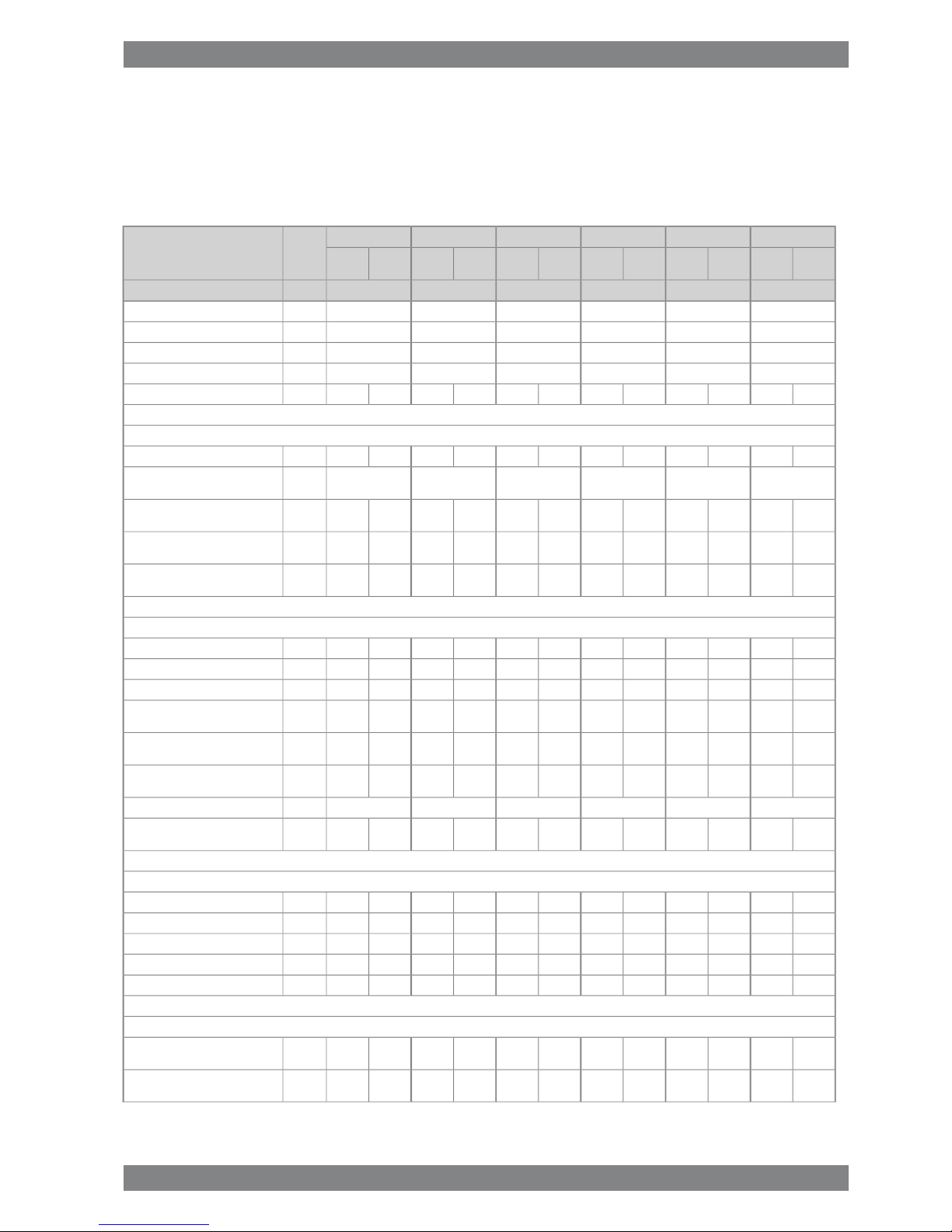
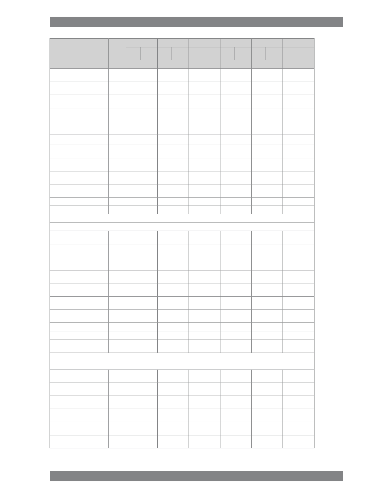
Table 1-1 Rating table for Wärtsilä 34DF
Generating setsMain engines
750 rpm
Cylinder
configuration
750 rpm720 rpm
Generator [kVA]Engine [kW]Generator [kVA]Engine [kW]Engine [kW]
36003000346028803000Wärtsilä 6L34DF
48004000461038404000Wärtsilä 8L34DF
54004500518043204500Wärtsilä 9L34DF
72006000691057606000Wärtsilä 12V34DF
96008000922076808000Wärtsilä 16V34DF
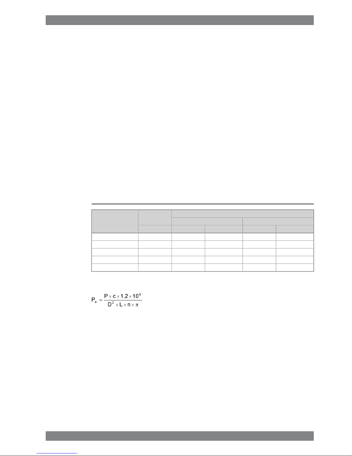
The mean effective pressure Pecan be calculated using the following formula:
where:
mean effective pressure [bar]Pe=
output per cylinder [kW]P =
engine speed [r/min]n =
cylinder diameter [mm]D =
length of piston stroke [mm]L =
operating cycle (4)c =
Wärtsilä 34DF Product Guide - a16 - 23 September 2016 1-1
1. Main Data and OutputsWärtsilä 34DF Product Guide

1.3 Output limitations in gas mode
1.3.1 Output limitations due to methane number and charge air
receiver temperature
Fig 1-1 Output limitations due to methane number and charge air receiver
temperature
1-2 Wärtsilä 34DF Product Guide - a16 - 23 September 2016
Wärtsilä 34DF Product Guide1. Main Data and Outputs

NOTE
Compensating a low methane number gas by lowering the charge air receiver
temperature below 45 °C is not allowed.
Minimum charge air receiver temperature is 35°C.
Compensating a higher charge air receiver temperature than 55 °C by a high
methane number gas is not allowed.
The dew point shall be calculated for the specific site conditions. The minimum
charge air receiver temperature shall be above the dew point, otherwise
condensation will occur in the charge air cooler.
Each +10 °C higher charge air receiver temperature from 45 °C means a 18 kPa
higher charge air pressure. This will have influence on the K
GAS
derating and on
the KTCderating calculation.
The charge air receiver temperature is approximately 5-10 °C higher than the
charge air coolant temperature at rated load.
Glycol usage in cooling water according to document DAAE062266.
Wärtsilä 34DF Product Guide - a16 - 23 September 2016 1-3
1. Main Data and OutputsWärtsilä 34DF Product Guide

1.3.2 Output limitations due to gas feed pressure and lower
heating value
Fig 1-2 Output limitations for gas feed pressure and LHV, 480/500kW per cylinder
NOTE
The above given values for gas feed pressure is before the engine (after the gas
regulating unit).
No compensation (uprating) of the engine output is allowed, neither for gas feed
pressure higher than required in the graph above nor lower heating value above
36 MJ/m
3
N
.
Values are given in m3Nis at 0 °C and 101.3 kPa.
If the gas pressure is lower than required, a pressure booster unit can be installed
before the gas regulating unit to ensure adequate gas pressure. If pressure arise
is not possible the engine output has to be adjusted according to above.
A 18 kPa higher gas feed pressure is required per 10 °C higher charge air receiver
temperature, due to increased charge air pressure.
1-4 Wärtsilä 34DF Product Guide - a16 - 23 September 2016
Wärtsilä 34DF Product Guide1. Main Data and Outputs

1.4 Reference conditions
The output is available within a range of ambient conditions and coolant temperatures specified
in the chapter Technical Data. The required fuel quality for maximum output is specified in the
section Fuel characteristics. For ambient conditions or fuel qualities outside the specification,
the output may have to be reduced.
The specific fuel consumption is stated in the chapter Technical Data. The statement applies
to engines operating in ambient conditions according to ISO 3046-1:2002 (E).
100 kPatotal barometric pressure
25°Cair temperature
30%relative humidity
25°Ccharge air coolant temperature
Correction factors for the fuel oil consumption in other ambient conditions are given in standard
ISO 3046-1:2002.
1.5 Operation in inclined position
Max. inclination angles at which the engine will operate satisfactorily.
Table 1-2 Inclination with Normal Oil Sump
15°
● Transverse inclination, permanent (list)
22.5°
● Transverse inclination, momentary (roll)
10°
● Longitudinal inclination, permanent (trim)
10°
● Longitudinal inclination, momentary (pitch)
Wärtsilä 34DF Product Guide - a16 - 23 September 2016 1-5
1. Main Data and OutputsWärtsilä 34DF Product Guide
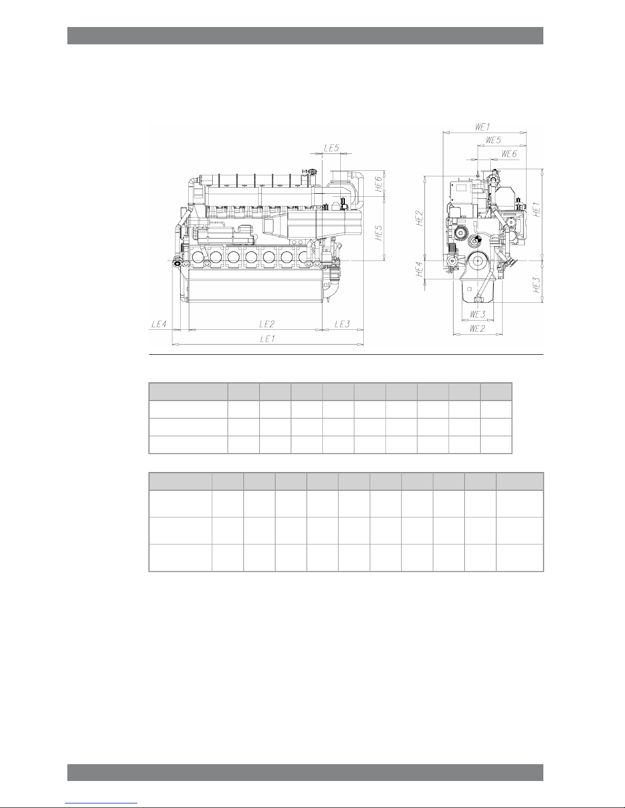
1.6 Principal dimensions and weights
1.6.1 Main engines
Fig 1-3 In-line engines (DAAF065806B)
LE4LE2HE3HE4HE2WE1HE1LE1kW/CylEngine
250367011555002345238025505325500Wärtsilä 6L34DF
250423011555002345261025505960500Wärtsilä 8L34DF
250514011555002345261025506869500Wärtsilä 9L34DF
WeightWE3LE5WE6HE6HE5LE3WE5WE2kW/CylEngine
35.488076510056101660121514251350500Wärtsilä
6L34DF
4488070513406071718128516501350500Wärtsilä
8L34DF
49.288070513406071718128516501350500Wärtsilä
9L34DF
All dimensions are in mm. Weight in metric tons with liquids (wet oil sump) but without flywheel.
1-6 Wärtsilä 34DF Product Guide - a16 - 23 September 2016
Wärtsilä 34DF Product Guide1. Main Data and Outputs
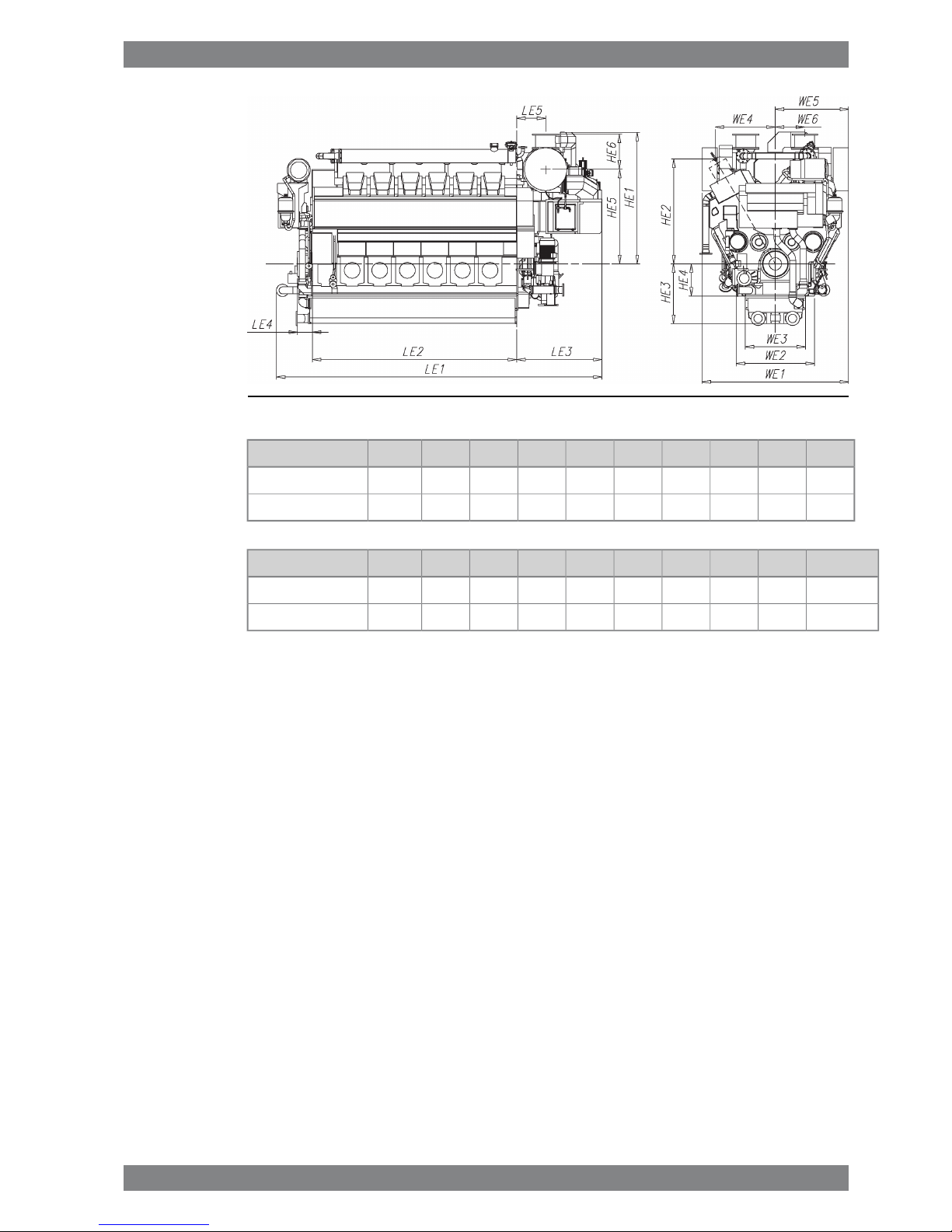
Fig 1-4 V-engines (DAAF066203)
WE3LE4LE2HE3HE4HE2WE1HE1LE1kW/CylEngine
1225300415012106502120290024356865500Wärtsilä 12V34DF
1225300527012106502120332525707905500Wärtsilä 16V34DF
WeightWE2LE5WE6HE6HE5WE4LE3WE5kW/CylEngine
611590555540460191585019851450500Wärtsilä 12V34DF
7715901225575550202085019251665500Wärtsilä 16V34DF
All dimensions are in mm. Weight in metric tons with liquids (wet oil sump) but without flywheel.
Wärtsilä 34DF Product Guide - a16 - 23 September 2016 1-7
1. Main Data and OutputsWärtsilä 34DF Product Guide
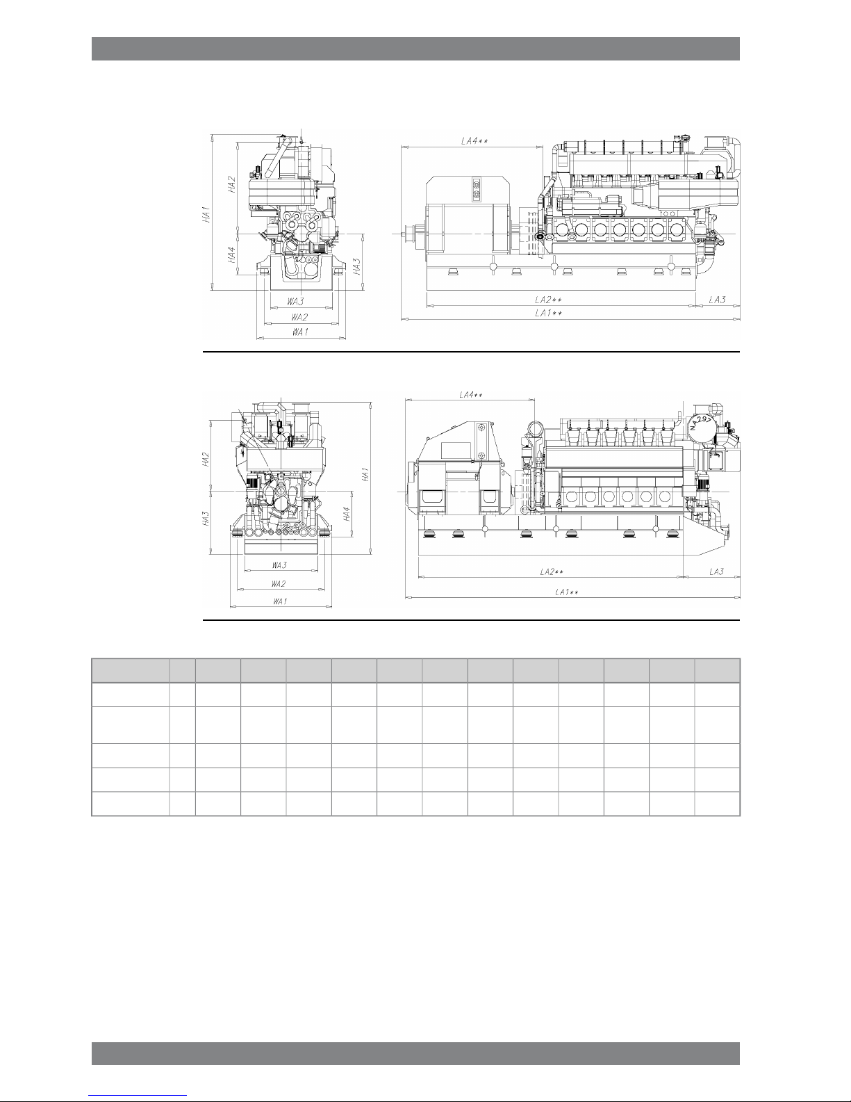
1.6.2 Generating sets
Fig 1-5 In-line engines (DAAE082427)
Fig 1-6 V engines (DAAE082975)
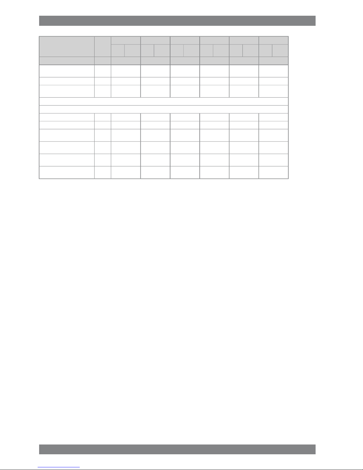
Weight**HA4HA3HA2HA1WA3WA2WA1LA4**LA3LA2**LA1**kW/cylEngine
6010551450234540001600191022903160121569008765480W 6L34DF
76105516302345418020002310269036451285865010410480Wärtsilä
8L34DF
87105516302345418022002510289038451285885010610480W 9L34DF
99137519002120433522002620306037751985795010260480W 12V34DF
124137518502120444525002920336037651925913011465480W 16V34DF
** Dependent on generator and flexible coupling.
All dimensions in mm. Weight in metric tons with liquids.
1-8 Wärtsilä 34DF Product Guide - a16 - 23 September 2016
Wärtsilä 34DF Product Guide1. Main Data and Outputs
2. Operating Ranges
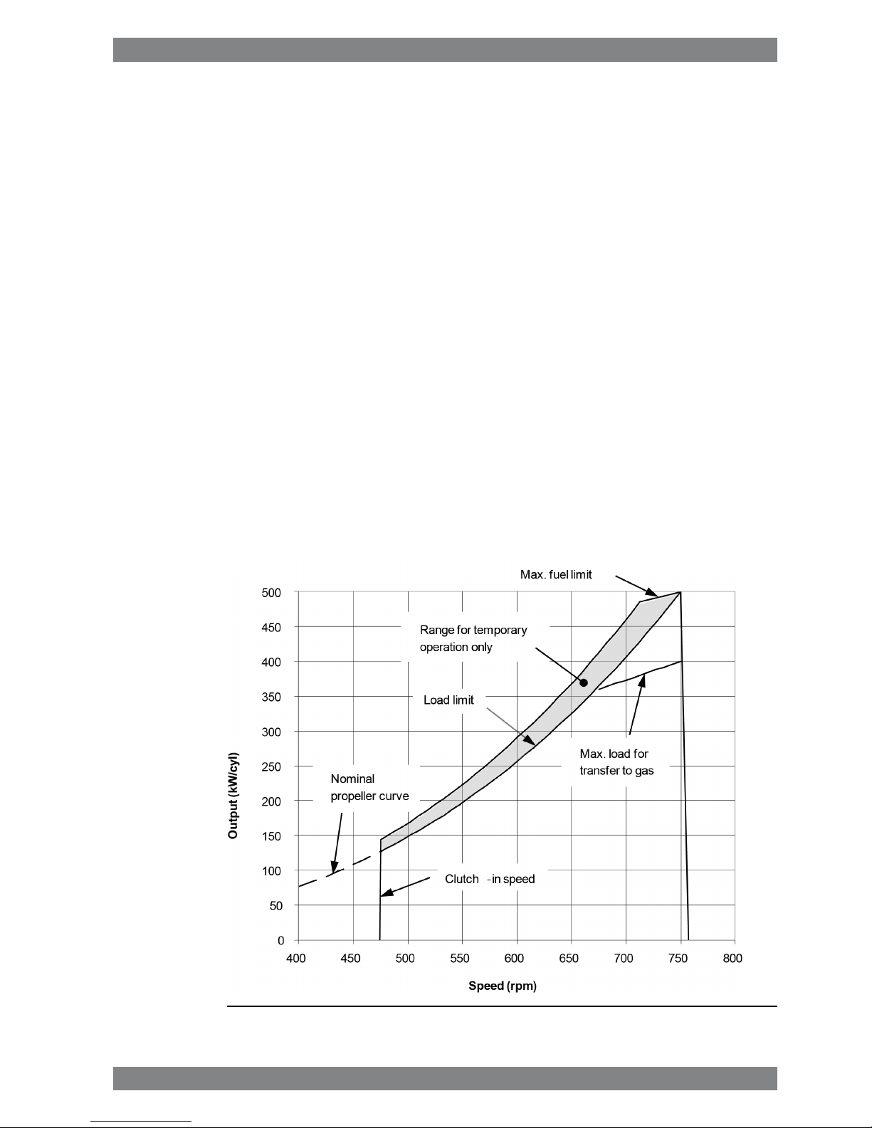
2.1 Engine operating range
Below nominal speed the load must be limited according to the diagrams in this chapter in
order to maintain engine operating parameters within acceptable limits. Operation in the
shaded area is permitted only temporarily during transients. Minimum speed is indicated in
the diagram, but project specific limitations may apply.
2.1.1 Controllable pitch propellers
An automatic load control system is required to protect the engine from overload. The load
control reduces the propeller pitch automatically, when a pre-programmed load versus speed
curve (“engine limit curve”) is exceeded, overriding the combinator curve if necessary. Engine
load is determined from measured shaft power and actual engine speed. The shaft power
meter is Wärtsilä supply.
The propulsion control must also include automatic limitation of the load increase rate.
Maximum loading rates can be found later in this chapter.
The propeller efficiency is highest at design pitch. It is common practice to dimension the
propeller so that the specified ship speed is attained with design pitch, nominal engine speed
and 85% output in the specified loading condition. The power demand from a possible shaft
generator or PTO must be taken into account. The 15% margin is a provision for weather
conditions and fouling of hull and propeller. An additional engine margin can be applied for
most economical operation of the engine, or to have reserve power.
Fig 2-1 Operating field for CP Propeller, rated speed 750 rpm
Wärtsilä 34DF Product Guide - a16 - 23 September 2016 2-1
2. Operating RangesWärtsilä 34DF Product Guide

Remarks: The maximum output may have to be reduced depending on gas properties and
gas pressure, refer to section "Derating of output in gas mode". The permissible output will
in such case be reduced with same percentage at all revolution speeds.
Restrictions for low load operation to be observed.
2.2 Loading capacity
Controlled load increase is essential for highly supercharged engines, because the turbocharger
needs time to accelerate before it can deliver the required amount of air. Sufficient time to
achieve even temperature distribution in engine components must also be ensured. Dual fuel
engines operating in gas mode require precise control of the air/fuel ratio, which makes
controlled load increase absolutely decisive for proper operation on gas fuel.
The loading ramp “preheated, normal gas” (see figures) can be used as the default loading
rate for both diesel and gas mode. If the control system has only one load increase ramp, then
the ramp for a preheated engine must be used. The HT-water temperature in a preheated
engine must be at least 60ºC, preferably 70ºC, and the lubricating oil temperature must be at
least 40ºC.
The loading ramp “max. capacity gas” indicates the maximum capability of the engine in gas
mode. Faster loading may result in alarms, knock and undesired trips to diesel. This ramp can
also be used as normal loading rate in diesel mode once the engine has attained normal
operating temperature.
The maximum loading rate “emergency diesel” is close to the maximum capability of the
engine in diesel mode. It shall not be used as the normal loading rate in diesel mode.
The load should always be applied gradually in normal operation. Acceptable load increments
are smaller in gas mode than in diesel mode and also smaller at high load, which must be
taken into account in applications with sudden load changes. The time between load increments
must be such that the maximum loading rate is not exceeded. In the case of electric power
generation, the classification society shall be contacted at an early stage in the project regarding
system specifications and engine loading capacity.
Electric generators must be capable of 10% overload. The maximum engine output is 110%
in diesel mode and 100% in gas mode. Transfer to diesel mode takes place automatically in
case of overload. Lower than specified methane number may also result in automatic transfer
to diesel when operating close to 100% output. Expected variations in gas fuel quality and
momentary load level must be taken into account to ensure that gas operation can be
maintained in normal operation.
2-2 Wärtsilä 34DF Product Guide - a16 - 23 September 2016
Wärtsilä 34DF Product Guide2. Operating Ranges
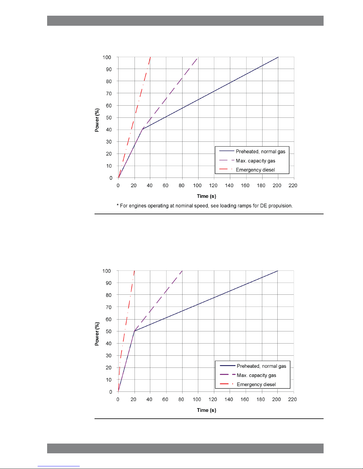
2.2.1 Mechanical propulsion, controllable pitch propeller (CPP)
Fig 2-2 Maximum load increase rates for variable speed engines
The propulsion control must not permit faster load reduction than 20 s from 100% to 0%
without automatic transfer to diesel first.
2.2.2 Constant speed applications
Fig 2-3 Increasing load successively from 0 to 100% MCR
Wärtsilä 34DF Product Guide - a16 - 23 September 2016 2-3
2. Operating RangesWärtsilä 34DF Product Guide
The propulsion control and the power management system must not permit faster load
reduction than 20 s from 100% to 0% without automatic transfer to diesel first.
In electric propulsion applications loading ramps are implemented both in the propulsion
control and in the power management system, or in the engine speed control in case
isochronous load sharing is applied. When the load sharing is based on speed droop, it must
be taken into account that the load increase rate of a recently connected generator is the sum
of the load transfer performed by the power management system and the load increase
performed by the propulsion control.
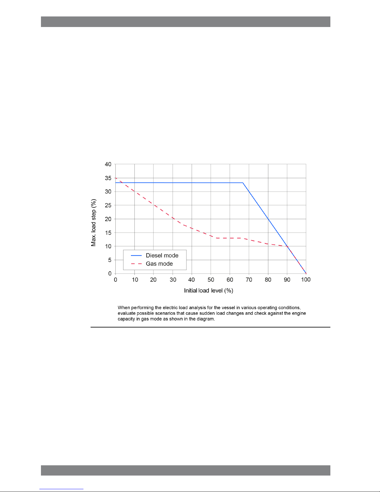
2.2.2.1 Maximum instant load steps
The electrical system must be designed so that tripping of breakers can be safely handled.
This requires that the engines are protected from load steps exceeding their maximum load
acceptance capability. If fast load shedding is complicated to implement or undesired, the
instant load step capacity can be increased with a fast acting signal that requests transfer to
diesel mode.
Fig 2-4 Maximum instant load steps in % of MCR, 500 kW/cyl
2.2.2.1.1 Gas mode
● Maximum step-wise load increases according to figure
● Steady-state frequency band ≤ 1.5 %
● Maximum speed drop 10 %
● Recovery time ≤ 10 s
● Time between load steps of maximum size ≥ 15 s
● Maximum step-wise load reductions: 100-75-45-0%
2.2.2.1.2 Diesel mode
● Maximum step-wise load increase 33% of MCR
● Steady-state frequency band ≤ 1.0 %
2-4 Wärtsilä 34DF Product Guide - a16 - 23 September 2016
Wärtsilä 34DF Product Guide2. Operating Ranges

● Maximum speed drop 10 %
● Recovery time ≤ 5 s
● Time between load steps of maximum size ≥ 8 s
2.2.2.1.3 Start-up
A stand-by generator reaches nominal speed in 50-70 seconds after the start signal (check
of pilot fuel injection is always performed during a normal start).
With black-out start active nominal speed is reached in about 25 s (pilot fuel injection disabled).
The engine can be started with gas mode selected provided that the engine is preheated and
the air receiver temperature is at required level. It will then start on MDF and gas fuel will be
used as soon as the pilot check is completed and the gas supply system is ready.
Start and stop on heavy fuel is not restricted.
2.3 Operation at low load and idling
Absolute idling (declutched main engine, disconnected generator):
● Maximum 10 minutes if the engine is to be stopped after the idling. 3-5 minutes idling
before stop is recommended.
● Maximum 8 hours if the engine is to be loaded after the idling.
Operation below 20 % load on HFO or below 10 % load on MDF or gas
● Maximum 100 hours continuous operation. At intervals of 100 operating hours the engine
must be loaded to minimum 70 % of the rated output for 1 hour. Before operating below
10% in gas mode, the engine must run above 10% load for at least 10 minutes. It is however
acceptable to change to gas mode directly after the engine has reached nominal speed
after the engine has started, provided that the charge air temperature is 55 °C.
Operation above 20 % load on HFO or above 10 % load on MDF or gas
● No restrictions.
2.4 Low air temperature
In cold conditions the following minimum inlet air temperatures apply:
Gas mode:
● Low load + 5ºC
● High load -10ºC
Diesel mode:
● Starting + 5ºC
● Idling - 5ºC
● High load - 10ºC
The two-stage charge air cooler is useful for heating of the charge air during prolonged low
load operation in cold conditions. Sustained operation between 0 and 40% load can however
require special provisions in cold conditions to prevent too low HT-water temperature. If
necessary, the preheating arrangement can be designed to heat the running engine (capacity
to be checked).
For further guidelines, see chapter Combustion air system design.
Wärtsilä 34DF Product Guide - a16 - 23 September 2016 2-5
2. Operating RangesWärtsilä 34DF Product Guide

This page intentionally left blank
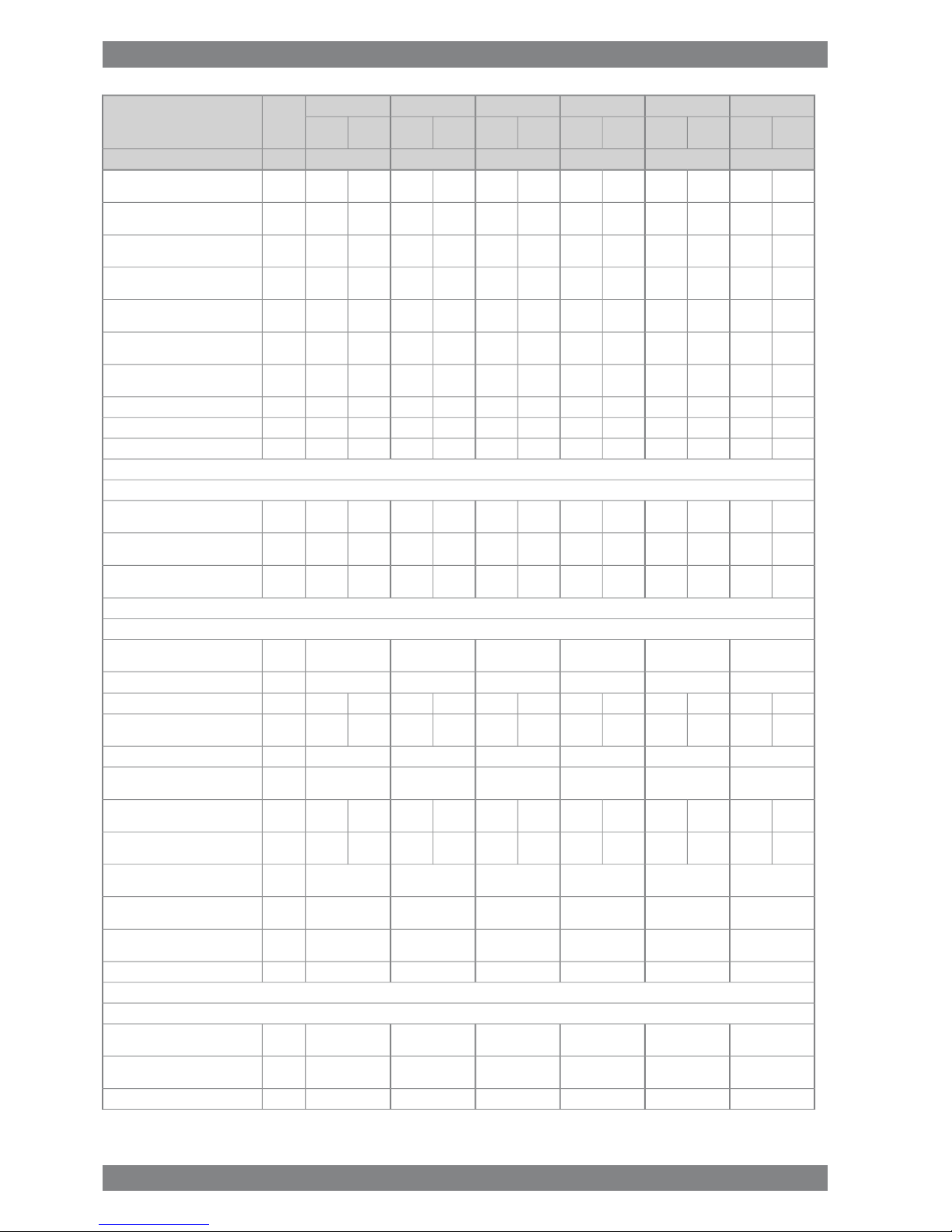
3. Technical Data
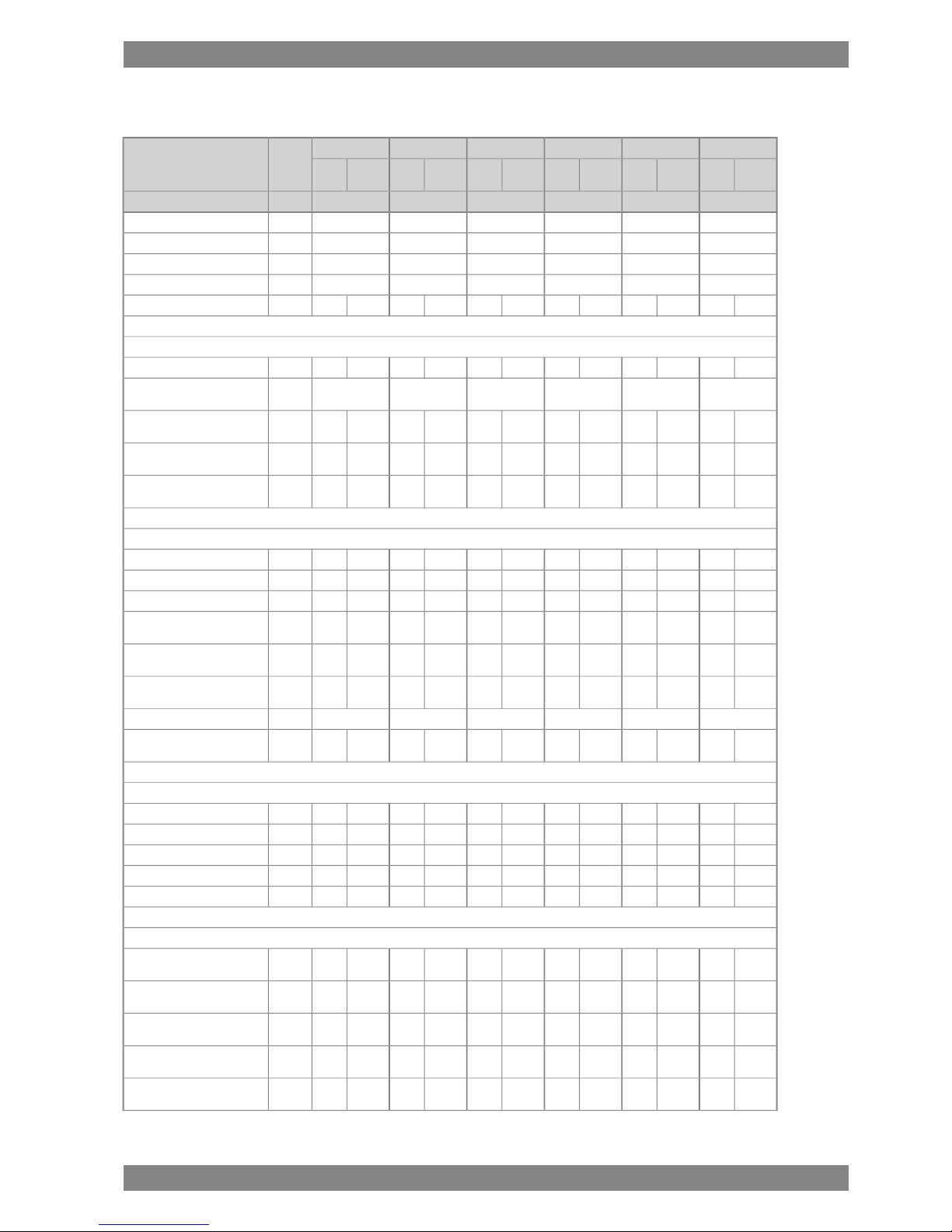
3.1 Wärtsilä 6L34DF
MEMEDEDEAUXAUX
Wärtsilä 6L34DF
Diesel
mode
Gas
mode
Diesel
mode
Gas
mode
Diesel
mode
Gas
mode
Diesel
mode
Gas
mode
Diesel
mode
Gas
mode
Diesel
mode
Gas
mode
500500500480500480kWCylinder output
750750750720750720rpmEngine speed
300030003000288030002880kWEngine output
2.22.22.22.22.22.2MPaMean effective pressure
VariableConstantConstantConstantConstantConstantSpeed mode
Tier 2Tier 3Tier 2Tier 3Tier 2Tier 3Tier 2Tier 3Tier 2Tier 3Tier 2Tier 3IMO compliance
Combustion air system (Note 1)
5.54.55.44.55.44.55.44.55.44.55.44.5kg/sFlow at 100% load
454545454545°CTemperature at turbocharger in-
take, max.
-45-45-45-45-45-45°CTemperature after air cooler (TE
601), load > 70%
-55-55-55-55-55-55°CTemperature after air cooler (TE
601), load 30...70%
50-50-50-50-50-50-°CTemperature after air cooler (TE
601)
Exhaust gas system (Note 2)
5.64.65.54.65.54.65.54.65.54.65.54.6kg/sFlow at 100% load
4.33.74.43.84.43.84.43.84.43.84.43.8kg/sFlow at 75% load
3.13.03.13.13.13.13.13.13.13.13.13.1kg/sFlow at 50% load
361381370381370381346362381381355362°CTemperature after turbocharger
at 100% load (TE 517)
348386340401340401318383349401327383°CTemperature after turbocharger
at 75% load (TE 517)
333340366402366402346386371402350386°CTemperature after turbocharger
at 50% load (TE 517)
444444kPaBackpressure, max.
605553603553603553591545608553596545mmCalculated exhaust diameter for
35 m/s
Heat balance at 100% load (Note 3)
443372425372425372406357430372410357kWJacket water, HT-circuit
966601933601933601933601933601933601kWCharge air, HT-circuit
184171179171179171179171179171179171kWCharge air, LT-circuit
281260261260261260250250264259252250kWLubricating oil, LT-circuit
123120121120121120116115123120117115kWRadiation
Fuel consumption (Note 4)
-7470-7470-7470-7470-7470-7470kJ/kWhTotal energy consumption at
100% load
-7570-7620-7620-7620-7620-7620kJ/kWhTotal energy consumption at 85%
load
Wärtsilä 34DF Product Guide - a16 - 23 September 2016 3-1
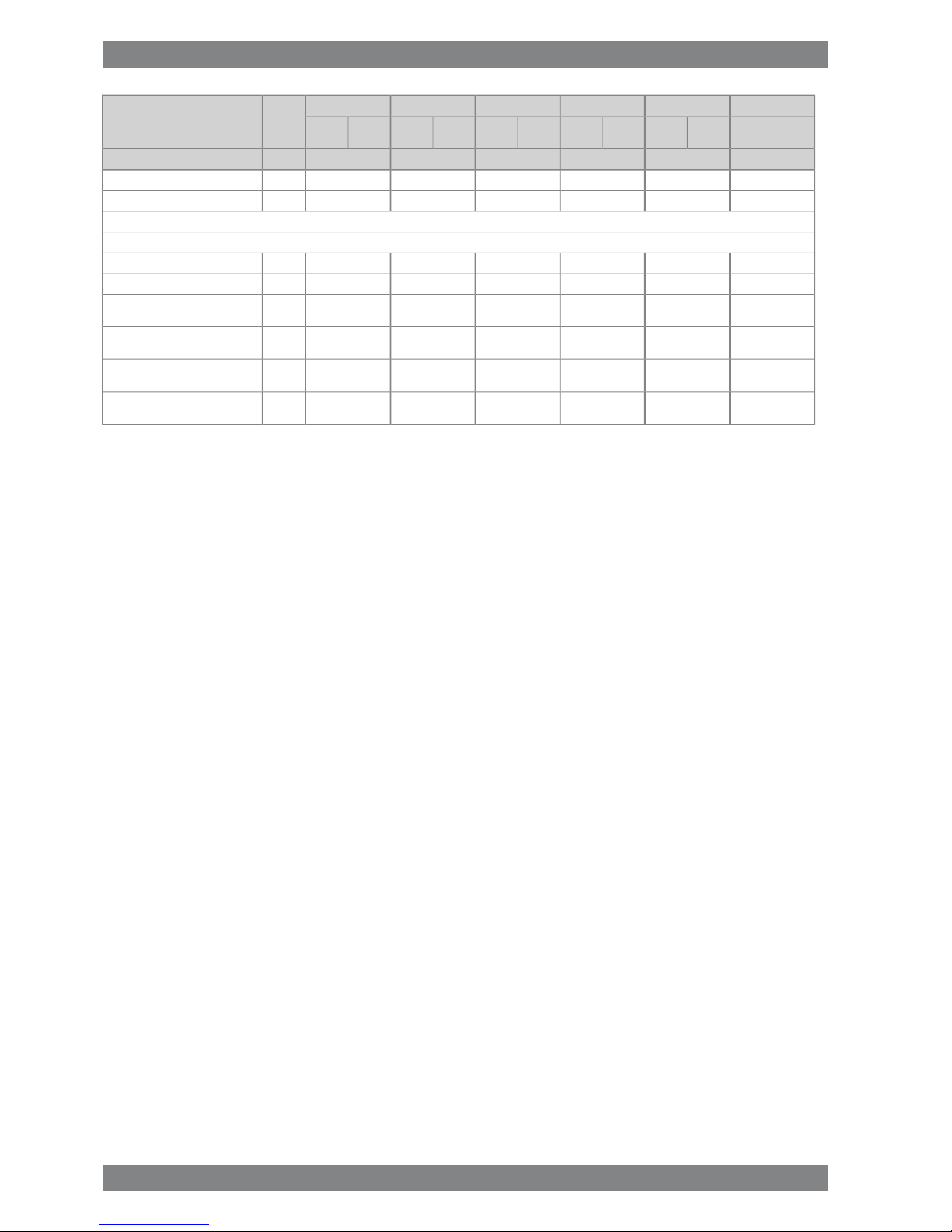
3. Technical DataWärtsilä 34DF Product Guide
MEMEDEDEAUXAUX
Wärtsilä 6L34DF
Diesel
mode
Gas
mode
Diesel
mode
Gas
mode
Diesel
mode
Gas
mode
Diesel
mode
Gas
mode
Diesel
mode
Gas
mode
Diesel
mode
Gas
mode
500500500480500480kWCylinder output
-7590-7850-7850-7850-7850-7850kJ/kWhTotal energy consumption at 75%
load
-7790-8600-8600-8600-8600-8600kJ/kWhTotal energy consumption at 50%
load
-7387-7387-7387-7387-7387-7387kJ/kWhFuel gas consumption at 100%
load
-7471-7527-7527-7527-7527-7527kJ/kWhFuel gas consumption at 85%
load
-7478-7743-7743-7743-7743-7743kJ/kWhFuel gas consumption at 75%
load
-7643-8435-8435-8435-8435-8435kJ/kWhFuel gas consumption at 50%
load
1901.91901.91901.91891.91921.91911.9g/kWhFuel oil consumption at 100%
load
1862.21872.21872.21862.21892.21882.2g/kWhFuel oil consumption at 85% load
1842.51872.51872.51862.51892.51882.5g/kWhFuel oil consumption at 75% load
1833.41953.81953.81943.81953.81943.8g/kWhFuel oil consumption 50% load
Fuel gas system (Note 5)
-535-535-535-535-535-535kPa (a)Gas pressure at engine inlet, min
(PT901)
-655-655-655-655-655-655kPa (a)Gas pressure to Gas Valve Unit,
min
-0...60-0...60-0...60-0...60-0...60-0...60°CGas temperature before Gas
Valve Unit
Fuel oil system
700±50700±50700±50700±50700±50700±50kPaPressure before injection pumps
(PT 101)
3.23.23.23.13.23.1m3/hFuel oil flow to engine, approx
16...24-16...24-16...24-16...24-16...24-16...24-cStHFO viscosity before the engine
140-140-140-140-140-140-°CMax. HFO temperature before
engine (TE 101)
2.02.02.02.02.02.0cStMDF viscosity, min.
454545454545°CMax. MDF temperature before
engine (TE 101)
2.42.32.32.22.32.2kg/hLeak fuel quantity (HFO), clean
fuel at 100% load
11.85.911.65.811.65.811.15.611.65.811.15.6kg/hLeak fuel quantity (MDF), clean
fuel at 100% load
2...112...112...112...112...112...11cStPilot fuel (MDF) viscosity before
the engine
550...750550...750550...750550...750550...750550...750kPa (a)Pilot fuel pressure at engine inlet
(PT 112)
150150150150150150kPaPilot fuel pressure drop after en-
gine, max
590590590590590590kg/hPilot fuel return flow at 100% load
Lubricating oil system
500500500500500500kPaPressure before bearings, nom.
(PT 201)
303030303030kPaSuction ability, including pipe
loss, max.
505050505050kPaPriming pressure, nom. (PT 201)
3-2 Wärtsilä 34DF Product Guide - a16 - 23 September 2016
Wärtsilä 34DF Product Guide3. Technical Data

MEMEDEDEAUXAUX
Wärtsilä 6L34DF
Diesel
mode
Gas
mode
Diesel
mode
Gas
mode
Diesel
mode
Gas
mode
Diesel
mode
Gas
mode
Diesel
mode
Gas
mode
Diesel
mode
Gas
mode
500500500480500480kWCylinder output
303030303030kPaSuction ability priming pump, in-
cluding pipe loss, max.
636363636363°CTemperature before bearings,
nom. (TE 201)
787878787878°CTemperature after engine, approx.
818181788178m3/hPump capacity (main), engine
driven
707070677067m3/hPump capacity (main), electrically
driven
15.0 / 18.015.0 / 18.015.0 / 18.015.0 / 18.015.0 / 18.015.0 / 18.0m3/hPriming pump capacity (50/60Hz)
1.61.61.61.61.61.6
m
3
Oil volume, wet sump, nom.
333333m
3
Oil volume in separate system oil
tank
0.40.40.40.40.40.4g/kWhOil consumption at 100% load,
approx.
840840840840840840l/minCrankcase ventilation flow rate at
full load
0.30.30.30.30.30.3kPaCrankcase ventilation backpres-
sure, max.
..................lOil volume in turning device
1.4...2.21.4...2.21.4...2.21.4...2.21.4...2.21.4...2.2lOil volume in speed governor
HT cooling water system
250 + static250 + static250 + static250 + static250 + static250 + statickPaPressure at engine, after pump,
nom. (PT 401)
530530530530530530kPaPressure at engine, after pump,
max. (PT 401)
858585858585°CTemperature before cylinders,
approx. (TE 401)
969696969696°CTemperature after engine, nom.
606060606060m3/hCapacity of engine driven pump,
nom.
100100100100100100kPaPressure drop over engine, total
100100100100100100
kPaPressure drop in external system,
max.
70...15070...15070...15070...15070...15070...150kPaPressure from expansion tank
0.410.410.410.410.410.41m
3
Water volume in engine
250250250250250250kPaDelivery head of stand-by pump
LT cooling water system
250+ static250+ static250+ static250+ static250+ static250+ statickPaPressure at engine, after pump,
nom. (PT 471)
530530530530530530kPaPressure at engine, after pump,
max. (PT 471)
383838383838°CTemperature before engine, max.
(TE 471)
252525252525°CTemperature before engine, min.
(TE 471)
606060606060m3/hCapacity of engine driven pump,
nom.
353535353535kPaPressure drop over charge air
cooler
100100100100100100
kPaPressure drop in external system,
max.
Wärtsilä 34DF Product Guide - a16 - 23 September 2016 3-3
3. Technical DataWärtsilä 34DF Product Guide
MEMEDEDEAUXAUX
Wärtsilä 6L34DF
Diesel
mode
Gas
mode
Diesel
mode
Gas
mode
Diesel
mode
Gas
mode
Diesel
mode
Gas
mode
Diesel
mode
Gas
mode
Diesel
mode
Gas
mode
500500500480500480kWCylinder output
70...15070...15070...15070...15070...15070...150kPaPressure from expansion tank
250250250250250250kPaDelivery head of stand-by pump
Starting air system (Note 6)
300030003000300030003000kPaPressure, nom.
300030003000300030003000kPaPressure, max.
150015001500150015001500kPaPressure at engine during start,
min. (alarm) (20°C)
160016001600160016001600kPaLow pressure limit in starting air
receiver
4.74.74.74.74.74.7Nm
3
Starting air consumption, start
(successful)
6.16.16.16.16.16.1Nm
3
Consumption per start (with
slowturn)
Notes:
At ISO 15550 conditions (ambient air temperature 25°C, LT-water 25°C) and 100% load. Flow tolerance 5%.Note 1
At ISO 15550 conditions (ambient air temperature 25°C, LT-water 25°C). Flow tolerance 5% and temperature tolerance
10°C in gas mode operation. Flow tolerance 8% and temperature tolerance 15°C in diesel mode operation.
Note 2
At 100% output and nominal speed. The figures are valid for ambient conditions according to ISO 15550 except for LTwater temperature, which is corresponding to charge air receiver temperature 45ºC in gas operation. With engine driven
water and lubricating oil pumps. Tolerance for cooling water heat 10%, tolerance for radiation heat 30%. Fouling factors
and a margin to be taken into account when dimensioning heat exchangers.
Note 3
At ambient conditions according to ISO 15550 and receiver temperature 45 °C. Lower calorific value 42 700 kJ/kg for
pilot fuel and 49 620 kJ/kg for gas fuel. With engine driven pumps (two cooling water pumps, one lubricating oil pump
and pilot fuel pump). Tolerance 5%.
Note 4
Fuel gas pressure given at LHV ≥ 36MJ/m³N. Required fuel gas pressure depends on fuel gas LHV and need to be increased
for lower LHV's. Pressure drop in external fuel gas system to be considered. See chapter Fuel system for further information.
Note 5
Minimum pressure for slow turning is 1800kPa.Note 6
ME = Engine driving propeller, variable speed
AE = Auxiliary engine driving generator
DE = Diesel-Electric engine driving generator
Subject to revision without notice.
3-4 Wärtsilä 34DF Product Guide - a16 - 23 September 2016
Wärtsilä 34DF Product Guide3. Technical Data

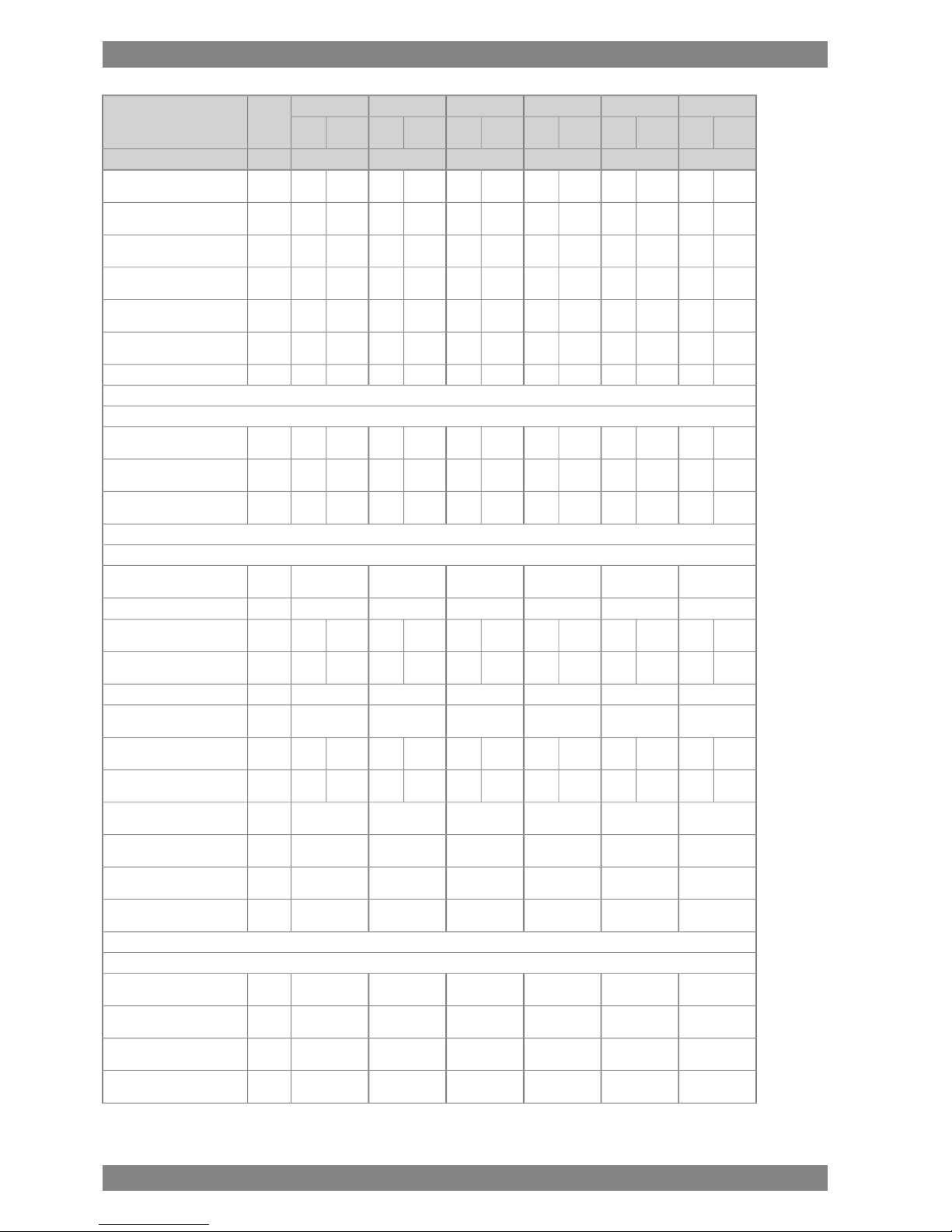
3.2 Wärtsilä 8L34DF
MEMEDEDEAUXAUX
Wärtsilä 8L34DF
Diesel
mode
Gas
mode
Diesel
mode
Gas
mode
Diesel
mode
Gas
mode
Diesel
mode
Gas
mode
Diesel
mode
Gas
mode
Diesel
mode
Gas
mode
500500500480500480kWCylinder output
750750750720750720rpmEngine speed
400040004000384040003840kWEngine output
2.22.22.22.22.22.2MPaMean effective pressure
VariableConstantConstantConstantConstantConstantSpeed mode
Tier 2Tier 3Tier 2Tier 3Tier 2Tier 3Tier 2Tier 3Tier 2Tier 3Tier 2Tier 3IMO compliance
Combustion air system (Note 1)
7.35.97.15.97.15.97.15.97.15.97.15.9kg/sFlow at 100% load
454545454545°CTemperature at turbocharger
intake, max.
-45-45-45-45-45-45°CTemperature after air cooler
(TE 601), load > 70%
-55-55-55-55-55-55°CTemperature after air cooler
(TE 601), load 30...70%
50-50-50-50-50-50-°CTemperature after air cooler
(TE 601)
Exhaust gas system (Note 2)
7.56.17.46.17.46.17.46.17.46.17.46.1kg/sFlow at 100% load
5.85.05.95.15.95.15.95.15.95.15.95.1kg/sFlow at 75% load
4.24.04.14.14.14.14.14.14.14.14.14.1kg/sFlow at 50% load
362381370381370381346362381381355362°CTemperature after turbochar-
ger at 100% load (TE 517)
349386340401340401318383349401327383°CTemperature after turbochar-
ger at 75% load (TE 517)
333341360402366402346386371402350386°CTemperature after turbochar-
ger at 50% load (TE 517)
444444kPaBackpressure, max.
700638696638696638683629702638688629mmCalculated exhaust diameter
for 35 m/s
Heat balance at 100% load (Note 3)
591497567496567496542476573496547476kWJacket water, HT-circuit
128880112448011244801124480112448011244801kWCharge air, HT-circuit
245228238228238228238228238228238228kWCharge air, LT-circuit
375347348347348347333333352346336333kWLubricating oil, LT-circuit
164160162160162160155154163160156154kWRadiation
Fuel consumption (Note 4)
-7470-7470-7470-7470-7470-7470kJ/kWhTotal energy consumption at
100% load
-7570-7620-7620-7620-7620-7620kJ/kWhTotal energy consumption at
85% load
-7590-7850-7850-7850-7850-7850kJ/kWhTotal energy consumption at
75% load
-7790-8600-8600-8600-8600-8600kJ/kWhTotal energy consumption at
50% load
-7387-7387-7387-7387-7387-7387kJ/kWhFuel gas consumption at
100% load
Wärtsilä 34DF Product Guide - a16 - 23 September 2016 3-5
3. Technical DataWärtsilä 34DF Product Guide
MEMEDEDEAUXAUX
Wärtsilä 8L34DF
Diesel
mode
Gas
mode
Diesel
mode
Gas
mode
Diesel
mode
Gas
mode
Diesel
mode
Gas
mode
Diesel
mode
Gas
mode
Diesel
mode
Gas
mode
500500500480500480kWCylinder output
-7471-7527-7527-7527-7527-7527kJ/kWhFuel gas consumption at 85%
load
-7478-7743-7743-7743-7743-7743kJ/kWhFuel gas consumption at 75%
load
-7643-8435-8435-8435-8435-8435kJ/kWhFuel gas consumption at 50%
load
1901.91901.91901.91891.91921.91911.9g/kWhFuel oil consumption at 100%
load
1862.21872.21872.21862.21892.21882.2g/kWhFuel oil consumption at 85%
load
1842.51872.51872.51862.51892.51882.5g/kWhFuel oil consumption at 75%
load
1833.41953.81953.81943.81953.81943.8g/kWhFuel oil consumption 50% load
Fuel gas system (Note 5)
-535-535-535-535-535-535kPa (a)Gas pressure at engine inlet,
min (PT901)
-655-655-655-655-655-655kPa (a)Gas pressure to Gas Valve
Unit, min
-0...60-0...60-0...60-0...60-0...60-0...60°CGas temperature before Gas
Valve Unit
Fuel oil system
700±50700±50700±50700±50700±50700±50kPaPressure before injection
pumps (PT 101)
4.34.34.34.14.34.1m3/hFuel oil flow to engine, approx
16...24-16...24-16...24-16...24-16...24-16...24-cStHFO viscosity before the en-
gine
140-140-140-140-140-140-°CMax. HFO temperature before
engine (TE 101)
2.02.02.02.02.02.0cStMDF viscosity, min.
454545454545°CMax. MDF temperature before
engine (TE 101)
3.13.13.13.03.13.0kg/hLeak fuel quantity (HFO), clean
fuel at 100% load
15.77.815.57.815.57.814.87.415.57.814.87.4kg/hLeak fuel quantity (MDF), clean
fuel at 100% load
2...112...112...112...112...112...11cStPilot fuel (MDF) viscosity be-
fore the engine
550...750550...750550...750550...750550...750550...750kPa (a)Pilot fuel pressure at engine
inlet (PT 112)
150150150150150150kPaPilot fuel pressure drop after
engine, max
590590590590635635kg/hPilot fuel return flow at 100%
load
Lubricating oil system
500500500500500500kPaPressure before bearings,
nom. (PT 201)
303030303030kPaSuction ability, including pipe
loss, max.
505050505050kPaPriming pressure, nom. (PT
201)
303030303030kPaSuction ability priming pump,
including pipe loss, max.
3-6 Wärtsilä 34DF Product Guide - a16 - 23 September 2016
Wärtsilä 34DF Product Guide3. Technical Data
MEMEDEDEAUXAUX
Wärtsilä 8L34DF
Diesel
mode
Gas
mode
Diesel
mode
Gas
mode
Diesel
mode
Gas
mode
Diesel
mode
Gas
mode
Diesel
mode
Gas
mode
Diesel
mode
Gas
mode
500500500480500480kWCylinder output
636363636363°CTemperature before bearings,
nom. (TE 201)
787878787878°CTemperature after engine, ap-
prox.
105105105101105101m3/hPump capacity (main), engine
driven
959595919591m3/hPump capacity (main), electric-
ally driven
21.6 / 25.921.6 / 25.921.6 / 25.921.6 / 25.921.6 / 25.921.6 / 25.9m3/hPriming pump capacity
(50/60Hz)
2.02.02.02.02.02.0
m
3
Oil volume, wet sump, nom.
444444m
3
Oil volume in separate system
oil tank
0.40.40.40.40.40.4g/kWhOil consumption at 100% load,
approx.
112011201120112011201120l/minCrankcase ventilation flow rate
at full load
0.30.30.30.30.30.3kPaCrankcase ventilation back-
pressure, max.
8.5...9.58.5...9.58.5...9.58.5...9.58.5...9.58.5...9.5lOil volume in turning device
1.4...2.21.4...2.21.4...2.21.4...2.21.4...2.21.4...2.2lOil volume in speed governor
HT cooling water system
250 + static250 + static250 + static250 + static250 + static250 + statickPaPressure at engine, after
pump, nom. (PT 401)
530530530530530530kPaPressure at engine, after
pump, max. (PT 401)
858585858585°CTemperature before cylinders,
approx. (TE 401)
969696969696°CTemperature after engine,
nom.
807575757575m3/hCapacity of engine driven
pump, nom.
100100100100100100kPaPressure drop over engine,
total
100100100100100100
kPaPressure drop in external sys-
tem, max.
70...15070...15070...15070...15070...15070...150kPaPressure from expansion tank
0.510.510.510.510.510.51m
3
Water volume in engine
250250250250250250kPaDelivery head of stand-by
pump
LT cooling water system
250+ static250+ static250+ static250+ static250+ static250+ statickPaPressure at engine, after
pump, nom. (PT 471)
530530530530530530kPaPressure at engine, after
pump, max. (PT 471)
383838383838°CTemperature before engine,
max. (TE 471)
252525252525°CTemperature before engine,
min. (TE 471)
807575757575m3/hCapacity of engine driven
pump, nom.
353535353535kPaPressure drop over charge air
cooler
Wärtsilä 34DF Product Guide - a16 - 23 September 2016 3-7
3. Technical DataWärtsilä 34DF Product Guide
MEMEDEDEAUXAUX
Wärtsilä 8L34DF
Diesel
mode
Gas
mode
Diesel
mode
Gas
mode
Diesel
mode
Gas
mode
Diesel
mode
Gas
mode
Diesel
mode
Gas
mode
Diesel
mode
Gas
mode
500500500480500480kWCylinder output
100100100100100100
kPaPressure drop in external sys-
tem, max.
70...15070...15070...15070...15070...15070...150kPaPressure from expansion tank
250250250250250250kPaDelivery head of stand-by
pump
Starting air system (Note 6)
300030003000300030003000kPaPressure, nom.
300030003000300030003000kPaPressure, max.
150015001500150015001500kPaPressure at engine during
start, min. (alarm) (20°C)
160016001600160016001600kPaLow pressure limit in starting
air receiver
5.75.75.75.75.75.7Nm
3
Starting air consumption, start
(successful)
7.47.47.47.47.47.4Nm
3
Consumption per start (with
slowturn)
Notes:
At ISO 15550 conditions (ambient air temperature 25°C, LT-water 25°C) and 100% load. Flow tolerance 5%.Note 1
At ISO 15550 conditions (ambient air temperature 25°C, LT-water 25°C). Flow tolerance 5% and temperature tolerance
10°C in gas mode operation. Flow tolerance 8% and temperature tolerance 15°C in diesel mode operation.
Note 2
At 100% output and nominal speed. The figures are valid for ambient conditions according to ISO 15550 except for LTwater temperature, which is corresponding to charge air receiver temperature 45ºC in gas operation. With engine driven
water and lubricating oil pumps. Tolerance for cooling water heat 10%, tolerance for radiation heat 30%. Fouling factors
and a margin to be taken into account when dimensioning heat exchangers.
Note 3
At ambient conditions according to ISO 15550 and receiver temperature 45 °C. Lower calorific value 42 700 kJ/kg for
pilot fuel and 49 620 kJ/kg for gas fuel. With engine driven pumps (two cooling water pumps, one lubricating oil pump
and pilot fuel pump). Tolerance 5%.
Note 4
Fuel gas pressure given at LHV ≥ 36MJ/m³N. Required fuel gas pressure depends on fuel gas LHV and need to be increased
for lower LHV's. Pressure drop in external fuel gas system to be considered. See chapter Fuel system for further information.
Note 5
Minimum pressure for slow turning is 1800kPa.Note 6
ME = Engine driving propeller, variable speed
AE = Auxiliary engine driving generator
DE = Diesel-Electric engine driving generator
Subject to revision without notice.
3-8 Wärtsilä 34DF Product Guide - a16 - 23 September 2016
Wärtsilä 34DF Product Guide3. Technical Data
3.3 Wärtsilä 9L34DF
MEMEDEDEAUXAUX
Wärtsilä 9L34DF
Diesel
mode
Gas
mode
Diesel
mode
Gas
mode
Diesel
mode
Gas
mode
Diesel
mode
Gas
mode
Diesel
mode
Gas
mode
Diesel
mode
Gas
mode
500500500480500480kWCylinder output
750750750720750720rpmEngine speed
450045004500432045004320kWEngine output
2.22.22.22.22.22.2MPaMean effective pressure
VariableConstantConstantConstantConstantConstantSpeed mode
Tier 2Tier 3Tier 2Tier 3Tier 2Tier 3Tier 2Tier 3Tier 2Tier 3Tier 2Tier 3IMO compliance
Combustion air system (Note 1)
8.26.78.06.78.06.78.06.78.06.78.06.7kg/sFlow at 100% load
454545454545°CTemperature at turbocharger
intake, max.
-45-45-45-45-45-45°CTemperature after air cooler
(TE 601), load > 70%
-55-55-55-55-55-55°CTemperature after air cooler
(TE 601), load 30...70%
50-50-50-50-50-50-°CTemperature after air cooler
(TE 601)
Exhaust gas system (Note 2)
8.56.88.36.88.36.88.36.88.36.88.36.8kg/sFlow at 100% load
6.55.66.75.86.75.86.75.86.75.86.75.8kg/sFlow at 75% load
4.74.54.64.64.64.64.64.64.64.64.64.6kg/sFlow at 50% load
361381370381370381346362381381355362°CTemperature after turbochar-
ger at 100% load (TE 517)
348386340401340401318383349401327383°CTemperature after turbochar-
ger at 75% load (TE 517)
333341366402366402346386371402350386°CTemperature after turbochar-
ger at 50% load (TE 517)
444444kPaBackpressure, max.
741677739677739677724667745677730667mmCalculated exhaust diameter
for 35 m/s
Heat balance at 100% load (Note 3)
664559638557638557609535645557616535kWJacket water, HT-circuit
144990113999011399901139990113999011399901kWCharge air, HT-circuit
275257268257268257268257268257268257kWCharge air, LT-circuit
422390392390392390374374396389378374kWLubricating oil, LT-circuit
184180182180182180174173184180176173kWRadiation
Fuel consumption (Note 4)
-7470-7470-7470-7470-7470-7470kJ/kWhTotal energy consumption at
100% load
-7570-7620-7620-7620-7620-7620kJ/kWhTotal energy consumption at
85% load
-7590-7850-7850-7850-7850-7850kJ/kWhTotal energy consumption at
75% load
-7790-8600-8600-8600-8600-8600kJ/kWhTotal energy consumption at
50% load
-7387-7387-7387-7387-7387-7387kJ/kWhFuel gas consumption at
100% load
Wärtsilä 34DF Product Guide - a16 - 23 September 2016 3-9
3. Technical DataWärtsilä 34DF Product Guide

MEMEDEDEAUXAUX
Wärtsilä 9L34DF
Diesel
mode
Gas
mode
Diesel
mode
Gas
mode
Diesel
mode
Gas
mode
Diesel
mode
Gas
mode
Diesel
mode
Gas
mode
Diesel
mode
Gas
mode
500500500480500480kWCylinder output
-7471-7527-7527-7527-7527-7527kJ/kWhFuel gas consumption at 85%
load
-7478-7743-7743-7743-7743-7743kJ/kWhFuel gas consumption at 75%
load
-7643-8435-8435-8435-8435-8435kJ/kWhFuel gas consumption at 50%
load
1901.91901.91901.91891.91921.91911.9g/kWhFuel oil consumption at 100%
load
1862.21872.21872.21862.21892.21882.2g/kWhFuel oil consumption at 85%
load
1842.51872.51872.51862.51892.51882.5g/kWhFuel oil consumption at 75%
load
1833.41953.81953.81943.81953.81943.8g/kWhFuel oil consumption 50% load
Fuel gas system (Note 5)
-535-535-535-535-535-535kPa (a)Gas pressure at engine inlet,
min (PT901)
-655-655-655-655-655-655kPa (a)Gas pressure to Gas Valve
Unit, min
-0...60-0...60-0...60-0...60-0...60-0...60°CGas temperature before Gas
Valve Unit
Fuel oil system
700±50700±50700±50700±50700±50700±50kPaPressure before injection
pumps (PT 101)
4.84.84.84.64.94.6m3/hFuel oil flow to engine, approx
16...24-16...24-16...24-16...24-16...24-16...24-cStHFO viscosity before the en-
gine
140-140-140-140-140-140-°CMax. HFO temperature before
engine (TE 101)
2.02.02.02.02.02.0cStMDF viscosity, min.
454545454545°CMax. MDF temperature before
engine (TE 101)
3.53.53.53.33.53.3kg/hLeak fuel quantity (HFO), clean
fuel at 100% load
17.68.817.58.717.58.716.78.317.58.716.78.3kg/hLeak fuel quantity (MDF), clean
fuel at 100% load
2...112...112...112...112...112...11cStPilot fuel (MDF) viscosity be-
fore the engine
550...750550...750550...750550...750550...750550...750kPa (a)Pilot fuel pressure at engine
inlet (PT 112)
150150150150150150kPaPilot fuel pressure drop after
engine, max
635635635635635635kg/hPilot fuel return flow at 100%
load
Lubricating oil system
500500500500500500kPaPressure before bearings,
nom. (PT 201)
303030303030kPaSuction ability, including pipe
loss, max.
505050505050kPaPriming pressure, nom. (PT
201)
303030303030kPaSuction ability priming pump,
including pipe loss, max.
3-10 Wärtsilä 34DF Product Guide - a16 - 23 September 2016
Wärtsilä 34DF Product Guide3. Technical Data
 Loading...