

Page 1
PRODUCT G U I D E
Wärtsilä 31
Page 2

© Copyright by WÄRTSILÄ FINLAND Oy
All rights reserved. No part of this booklet may be reproduced or copied in any form or by any means (electronic,
mechanical, graphic, photocopying, recording, taping or other information retrieval systems) without the prior written
permission of the copyright owner.
THIS PUBLICATION IS DESIGNED TO PROVIDE AN ACCURATE AND AUTHORITATIVE INFORMATION WITH
REGARD TO THE SUBJECT-MATTER COVERED AS WAS AVAILABLE AT THE TIME OF PRINTING. HOWEVER,THE
PUBLICATION DEALS WITH COMPLICATED TECHNICAL MATTERS SUITED ONLY FOR SPECIALISTS IN THE
AREA, AND THE DESIGN OF THE SUBJECT-PRODUCTS IS SUBJECT TO REGULAR IMPROVEMENTS,
MODIFICATIONS AND CHANGES. CONSEQUENTLY, THE PUBLISHER AND COPYRIGHT OWNER OF THIS
PUBLICATION CAN NOT ACCEPT ANY RESPONSIBILITY OR LIABILITY FOR ANY EVENTUAL ERRORS OR
OMISSIONS IN THIS BOOKLET OR FOR DISCREPANCIES ARISING FROM THE FEATURES OF ANY ACTUAL ITEM
IN THE RESPECTIVE PRODUCT BEING DIFFERENT FROM THOSE SHOWN IN THIS PUBLICATION. THE PUBLISHER
AND COPYRIGHT OWNER SHALL UNDER NO CIRCUMSTANCES BE HELD LIABLE FOR ANY FINANCIAL
CONSEQUENTIAL DAMAGES OR OTHER LOSS, OR ANY OTHER DAMAGE OR INJURY, SUFFERED BY ANY
PARTY MAKING USE OF THIS PUBLICATION OR THE INFORMATION CONTAINED HEREIN.
Page 3

Introduction
This Product Guide provides data and system proposals for the early design phase of marine
engine installations. For contracted projects specific instructions for planning the installation
are always delivered. Any data and information herein is subject to revision without notice.
UpdatesPublishedIssue
First version of Product Guide W3118.10.20161/2016
Wärtsilä, Marine Solutions
Vaasa, October 2016
Wärtsilä 31 Product Guide - a1 - 18 October 2016 iii
IntroductionWärtsilä 31 Product Guide
Page 4

Table of contents
1-11. Main Data and Outputs .......................................................................................................................
1-11.1 Maximum continuous output .......................................................................................................
1-21.2 Reference conditions ...................................................................................................................
1-21.3 Operation in inclined position .....................................................................................................
1-31.4 Dimensions and weights .............................................................................................................
2-12. Operating Ranges ................................................................................................................................
2-12.1 Engine operating range ...............................................................................................................
2-22.2 Loading capacity .........................................................................................................................
2-42.3 Operation at low load and idling ..................................................................................................
2-42.4 Low air temperature ....................................................................................................................
3-13. Technical Data ......................................................................................................................................
3-13.1 Wärtsilä 8V31 ...............................................................................................................................
3-43.2 Wärtsilä 10V31 .............................................................................................................................
3-73.3 Wärtsilä 12V31 .............................................................................................................................
3-103.4 Wärtsilä 14V31 .............................................................................................................................
3-133.5 Wärtsilä 16V31 .............................................................................................................................
4-14. Description of the Engine ....................................................................................................................
4-14.1 Definitions ....................................................................................................................................
4-14.2 Main components and systems ..................................................................................................
4-54.3 Expected overhaul intervals and life times ..................................................................................
4-54.4 Engine storage .............................................................................................................................
5-15. Piping Design, Treatment and Installation .........................................................................................
5-15.1 Pipe dimensions ..........................................................................................................................
5-25.2 Trace heating ...............................................................................................................................
5-25.3 Pressure class ..............................................................................................................................
5-35.4 Pipe class ....................................................................................................................................
5-45.5 Insulation .....................................................................................................................................
5-45.6 Local gauges ...............................................................................................................................
5-45.7 Cleaning procedures ...................................................................................................................
5-55.8 Flexible pipe connections ............................................................................................................
5-65.9 Clamping of pipes ........................................................................................................................
6-16. Fuel Oil System ....................................................................................................................................
6-16.1 Acceptable fuel characteristics ...................................................................................................
6-56.2 Internal fuel oil system .................................................................................................................
6-86.3 External fuel oil system ................................................................................................................
7-17. Lubricating Oil System ........................................................................................................................
7-17.1 Lubricating oil requirements ........................................................................................................
7-27.2 Internal lubricating oil system ......................................................................................................
7-57.3 External lubricating oil system .....................................................................................................
7-117.4 Crankcase ventilation system ......................................................................................................
7-137.5 Flushing instructions ....................................................................................................................
8-18. Compressed Air System ......................................................................................................................
8-18.1 Instrument air quality ...................................................................................................................
8-18.2 Internal compressed air system ..................................................................................................
8-38.3 External compressed air system .................................................................................................
iv Wärtsilä 31 Product Guide - a1 - 18 October 2016
Wärtsilä 31 Product GuideTable of contents
Page 5

9-19. Cooling Water System .........................................................................................................................
9-19.1 Water quality ...............................................................................................................................
9-29.2 Internal cooling water system ......................................................................................................
9-89.3 External cooling water system ....................................................................................................
10-110. Exhaust Gas System ............................................................................................................................
10-110.1 Internal exhaust gas system ........................................................................................................
10-410.2 Exhaust gas outlet .......................................................................................................................
10-610.3 External exhaust gas system .......................................................................................................
11-111. Turbocharger Cleaning ........................................................................................................................
11-111.1 Turbine cleaning system ..............................................................................................................
11-211.2 Compressor cleaning system ......................................................................................................
12-112. Exhaust Emissions ...............................................................................................................................
12-112.1 Diesel engine exhaust components ............................................................................................
12-212.2 Marine exhaust emissions legislation ..........................................................................................
12-612.3 Methods to reduce exhaust emissions ........................................................................................
13-113. Automation System .............................................................................................................................
13-113.1 Technical data and system overview ...........................................................................................
13-513.2 Functions ....................................................................................................................................
13-713.3 Alarm and monitoring signals ......................................................................................................
13-713.4 Electrical consumers ...................................................................................................................
13-913.5 System requirements and guidelines for diesel-electric propulsion ............................................
14-114. Foundation ............................................................................................................................................
14-114.1 Steel structure design ..................................................................................................................
14-114.2 Mounting of main engines ...........................................................................................................
14-814.3 Mounting of generating sets ........................................................................................................
14-1014.4 Flexible pipe connections ............................................................................................................
15-115. Vibration and Noise ..............................................................................................................................
15-115.1 External forces and couples ........................................................................................................
15-215.2 Torque variations .........................................................................................................................
15-215.3 Mass moments of inertia .............................................................................................................
15-215.4 Air borne noise .............................................................................................................................
15-315.5 Exhaust noise ..............................................................................................................................
16-116. Power Transmission ............................................................................................................................
16-116.1 Flexible coupling ..........................................................................................................................
17-117. Engine Room Layout ...........................................................................................................................
17-117.1 Space requirements for maintenance .........................................................................................
17-117.2 Transportation and storage of spare parts and tools ..................................................................
17-217.3 Required deck area for service work ...........................................................................................
18-118. Transport Dimensions and Weights ...................................................................................................
18-118.1 Lifting of main engines ................................................................................................................
18-218.2 Lifting of generating sets .............................................................................................................
18-318.3 Engine components .....................................................................................................................
19-119. Product Guide Attachments ...............................................................................................................
20-120. ANNEX ...................................................................................................................................................
20-120.1 Unit conversion tables .................................................................................................................
20-220.2 Collection of drawing symbols used in drawings ........................................................................
Wärtsilä 31 Product Guide - a1 - 18 October 2016 v
Table of contentsWärtsilä 31 Product Guide
Page 6

This page intentionally left blank
Page 7
1. Main Data and Outputs
The Wärtsilä 31 is a 4-stroke, non-reversible, turbocharged and intercooled diesel engine with
direct fuel injection.
310 mmCylinder bore ........................
430 mmStroke ...................................
2 inlet valves
2 exhaust valves
Number of valves .................
8, 10, 12, 14 and 16Cylinder configuration .........
50°V-angle .................................
Clockwise, counterclockwiseDirection of rotation .............
720, 750 rpmSpeed ...................................
10.32 - 10.75 m/sMean piston speed ...............
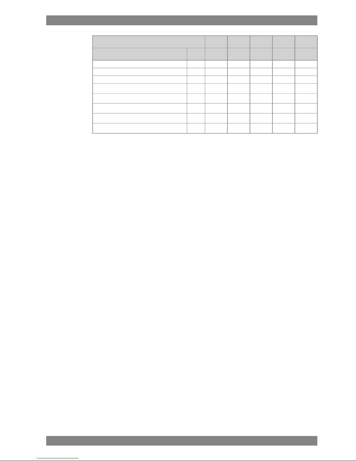
1.1 Maximum continuous output
Table 1-1 Rating table for Wärtsilä 31
Generating setsMain enginesCylinder
configuration
750 rpm720 rpm750 rpm
Generator [kVA]Engine [kW]Generator [kVA]Engine [kW][kW]
58564880566447204880W 8V31
73206100708059006100W 10V31
87847320849670807320W 12V31
102488540991282608540W 14V31
1171297601132894409760W 16V31
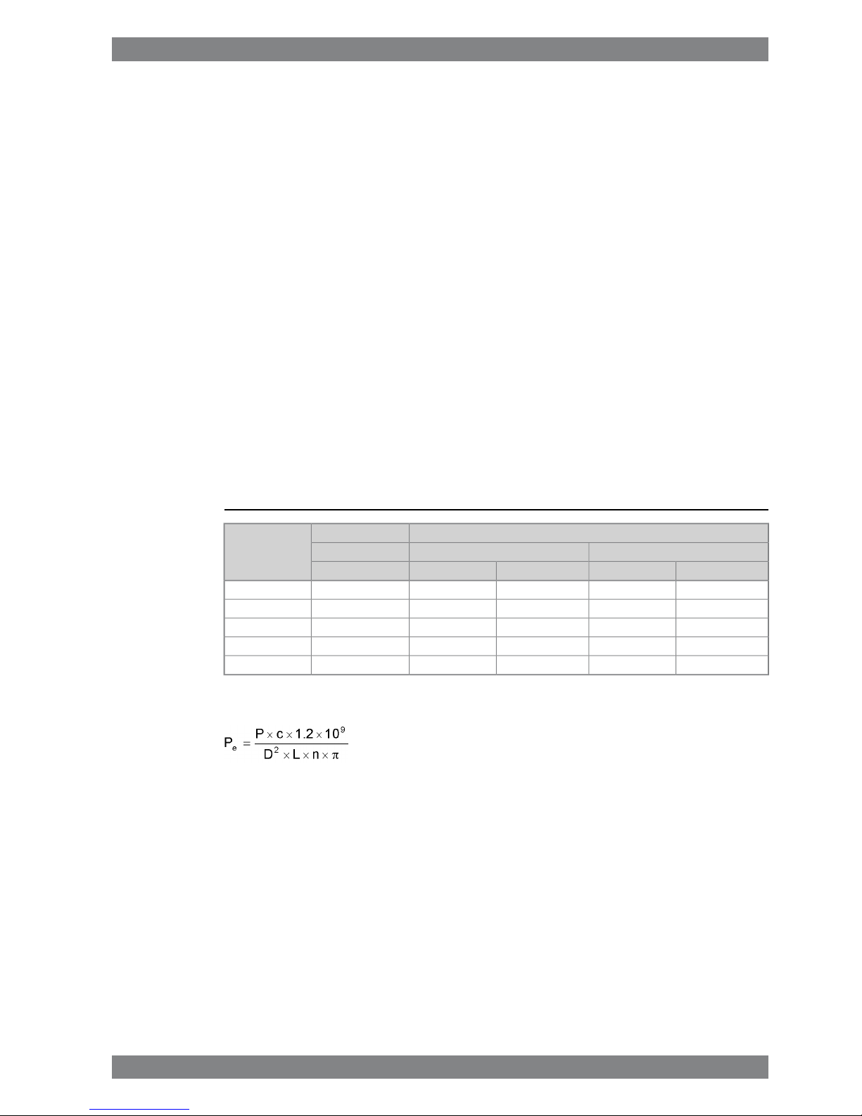
The mean effective pressure Pe can be calculated as follows:
where:
mean effective pressure [bar]Pe =
output per cylinder [kW]P =
engine speed [r/min]n =
cylinder diameter [mm]D =
length of piston stroke [mm]L =
operating cycle (4)c =
Wärtsilä 31 Product Guide - a1 - 18 October 2016 1-1
1. Main Data and OutputsWärtsilä 31 Product Guide
Page 8

1.2 Reference conditions
The output is available up to a charge air coolant temperature of max. 38°C and an air
temperature of max. 45°C. For higher temperatures, the output has to be reduced according
to the formula stated in ISO 3046-1:2002 (E).
The specific fuel oil consumption is stated in the chapter Technical data. The stated specific
fuel oil consumption applies to engines with engine driven pumps, operating in ambient
conditions according to ISO 15550:2002 (E). The ISO standard reference conditions are:
100 kPatotal barometric pressure
25°Cair temperature
30%relative humidity
25°Ccharge air coolant temperature
Correction factors for the fuel oil consumption in other ambient conditions are given in standard
ISO 3046-1:2002.
1.3 Operation in inclined position
Max. inclination angles at which the engine will operate satisfactorily.
Table 1-2 Inclination with Normal Oil Sump
15°
● Transverse inclination, permanent (list)
22.5°
● Transverse inclination, momentary (roll)
10°
● Longitudinal inclination, permanent (trim)
10°
● Longitudinal inclination, momentary (pitch)
NOTE
Inclination in all directions requires special arrangements.
1-2 Wärtsilä 31 Product Guide - a1 - 18 October 2016
Wärtsilä 31 Product Guide1. Main Data and Outputs
Page 9
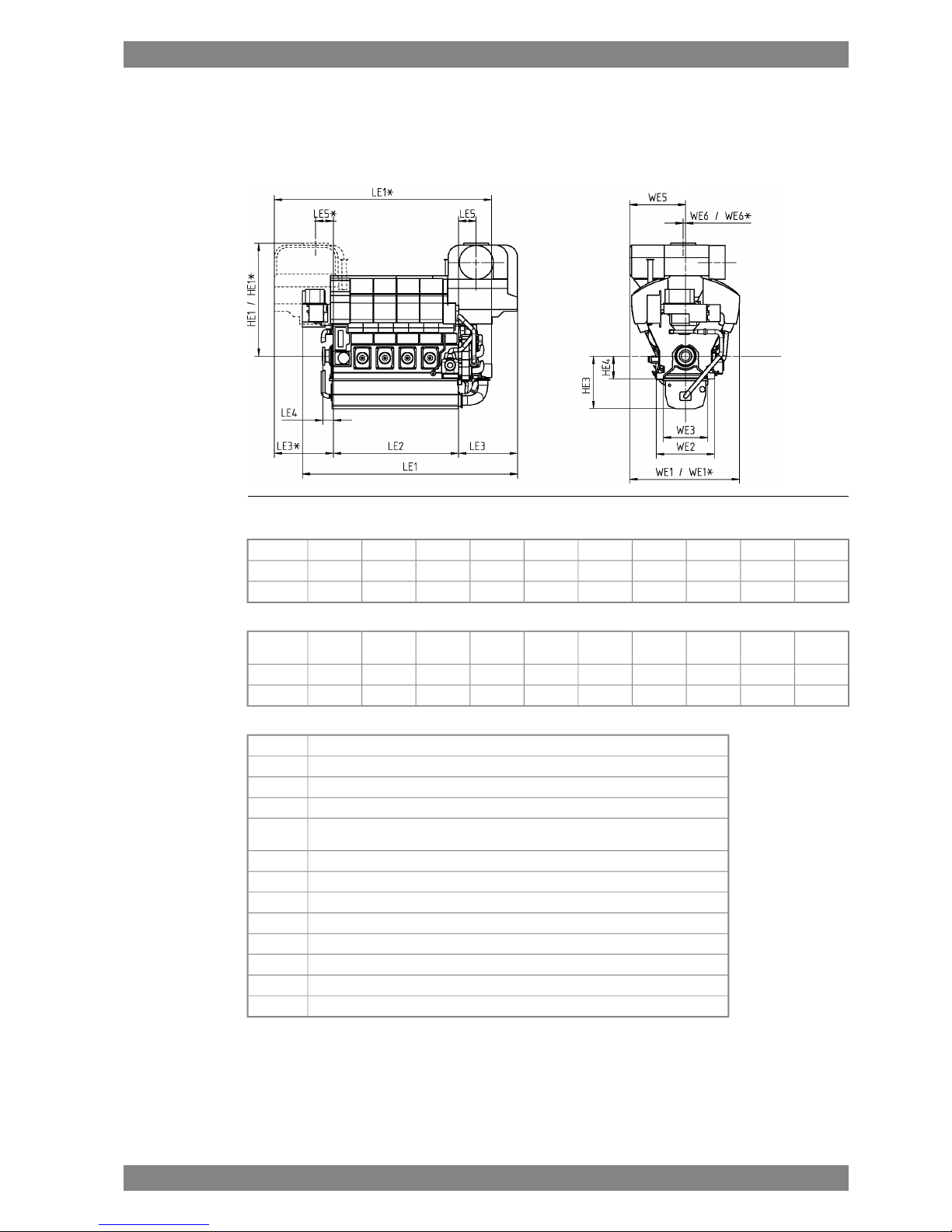
1.4 Dimensions and weights
1.4.1 Main engines
Fig 1-1 Main engine dimensions (DAAF336230)
LE4LE2HE3HE4WE1*WE1HE1*HE1LE1LE1*Engine
35035601496650311331133205320561146175W8V31
35042001496650311331133205320567546813W10V31
Weight
ton**
WE2WE3LE5LE5*WE6WE6*LE3LE3*WESEngine
56.71650115350050067-67167516751582W8V31
621650115350050067-67167516751585W10V31
Total length of engineLE1
Height from the crankshaft centerline to the highest pointHE1
Total width of the engineWE1
Height from the crankshaft centerline to the engine feetsHE4
Dimension from the crankshaft centerline to the bottom of the oil sump, when shallow oil
sump
HE3
Length of the engine blockLE2
Dimension from the end of the block to the end of the crankshaftLE4
Width of the oil sumpWE3
Width of the engine block at the engine feetWE2
Dimension from the center of the crankshaft to the outermost point of the engineWE5
Dimension from the engine block to the outermost point in turbocharger endLE3
Dimension from the center of the crankshaft to the centre of the exhaust outletWE6
Dimension from the end of the engine block to the centre of the exhaust gas outletLE5
* Turbocharger at flywheel end
** Weight with liquids (wet sump) but without flywheel
All dimensions in mm.
Wärtsilä 31 Product Guide - a1 - 18 October 2016 1-3
1. Main Data and OutputsWärtsilä 31 Product Guide
Page 10

This page intentionally left blank
Page 11
2. Operating Ranges
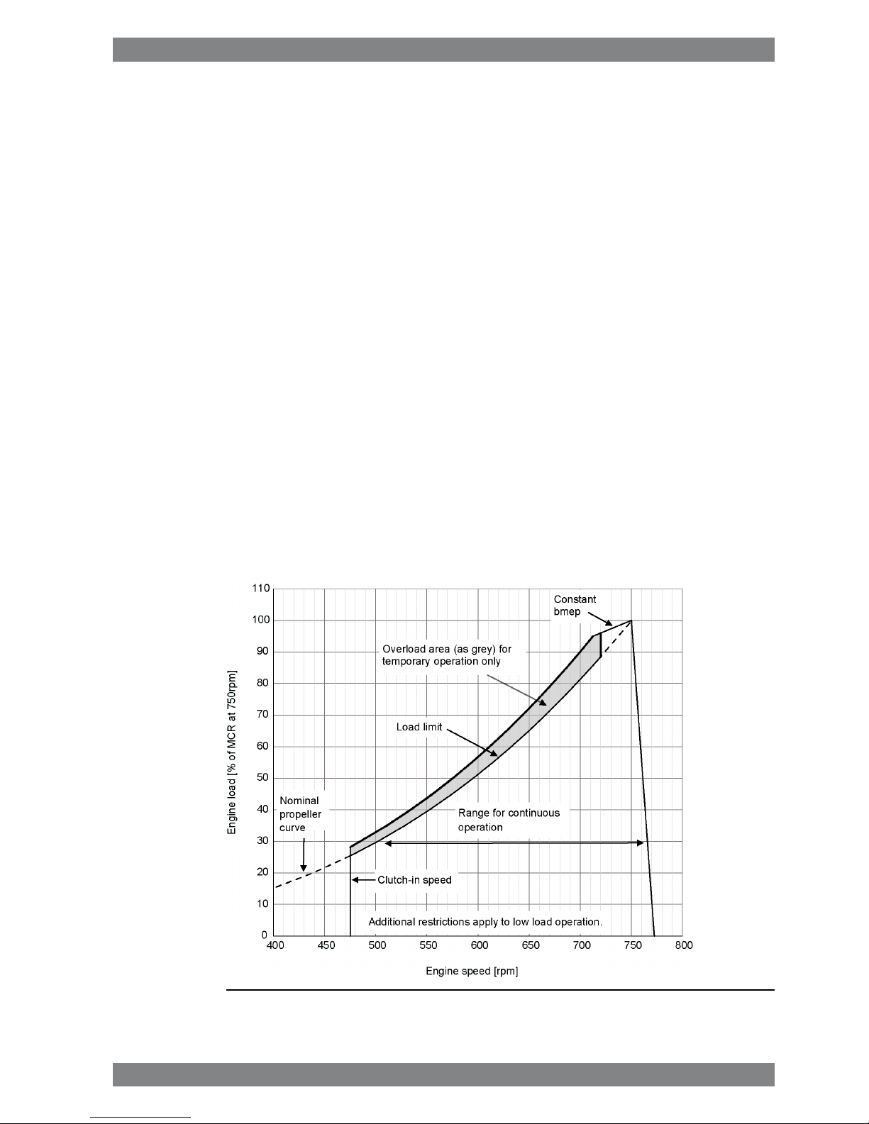
2.1 Engine operating range
Below nominal speed the load must be limited according to the diagrams in this chapter in
order to maintain engine operating parameters within acceptable limits. Operation in the
shaded area is permitted only temporarily during transients. Minimum speed is indicated in
the diagram, but project specific limitations may apply.
2.1.1 Controllable pitch propellers
The engine load must be limited according to the diagram below when operating below nominal
speed, in order to maintain engine operating parameters within acceptable limits. Operation
in the shaded area is permitted only temporarily during transients to permit smooth overload
control.
Note that project specific vibration calculations may result in higher minimum speed than in
the diagram below.
The propulsion control must also include automatic limitation of the load increase rate.
Maximum loading rates can be found later in this chapter.
The propeller efficiency is highest at design pitch. It is common practice to dimension the
propeller so that the specified ship speed is attained with design pitch, nominal engine speed
and 85% output in the specified loading condition. The power demand from a possible shaft
generator or PTO must be taken into account. The 15% margin is a provision for weather
conditions and fouling of hull and propeller. An additional engine margin can be applied for
most economical operation of the engine, or to have reserve power.
Fig 2-1 Operating field for CP Propeller
Wärtsilä 31 Product Guide - a1 - 18 October 2016 2-1
2. Operating RangesWärtsilä 31 Product Guide
Page 12

2.2 Loading capacity
Controlled load increase is essential for highly supercharged diesel engines, because the
turbocharger needs time to accelerate before it can deliver the required amount of air. A slower
loading ramp than the maximum capability of the engine permits a more even temperature
distribution in engine components during transients.
The engine can be loaded immediately after start, provided that the engine is pre-heated to
a HT-water temperature of min 70ºC, and the lubricating oil temperature is min. 40 ºC.
The ramp for normal loading applies to engines that have reached normal operating
temperature.
2.2.1 Mechanical propulsion
Fig 2-2 Maximum recommended load increase rates for variable speed engines
The propulsion control must include automatic limitation of the load increase rate. If the control
system has only one load increase ramp, then the ramp for a preheated engine should be
used. In tug applications the engines have usually reached normal operating temperature
before the tug starts assisting. The “emergency” curve is close to the maximum capability of
the engine.
Large load reductions from high load should also be performed gradually. In normal operation
the load should not be reduced from 100% to 0% in less than 15 seconds. When absolutely
necessary, the load can be reduced as fast as the pitch setting system can react (overspeed
due to windmilling must be considered for high speed ships).
2-2 Wärtsilä 31 Product Guide - a1 - 18 October 2016
Wärtsilä 31 Product Guide2. Operating Ranges
Page 13

2.2.2 Diesel electric propulsion and auxiliary engines
Fig 2-3 Maximum recommended load increase rates for engines operating at
nominal speed
In diesel electric installations loading ramps are implemented both in the propulsion control
and in the power management system, or in the engine speed control in case isochronous
load sharing is applied. If a ramp without knee-point is used, it should not achieve 100% load
in shorter time than the ramp in the figure. When the load sharing is based on speed droop,
the load increase rate of a recently connected generator is the sum of the load transfer
performed by the power management system and the load increase performed by the
propulsion control.
The “emergency” curve is close to the maximum capability of the engine and it shall not be
used as the normal limit. In dynamic positioning applications loading ramps corresponding to
20-30 seconds from zero to full load are however normal. If the vessel has also other operating
modes, a slower loading ramp is recommended for these operating modes.
In typical auxiliary engine applications there is usually no single consumer being decisive for
the loading rate. It is recommended to group electrical equipment so that the load is increased
in small increments, and the resulting loading rate roughly corresponds to the “normal” curve.
In normal operation the load should not be reduced from 100% to 0% in less than 15 seconds.
If the application requires frequent unloading at a significantly faster rate, special arrangements
can be necessary on the engine. In an emergency situation the full load can be thrown off
instantly.
2.2.2.1 Maximum instant load steps
The electrical system must be designed so that tripping of breakers can be safely handled.
This requires that the engines are protected from load steps exceeding their maximum load
acceptance capability. The load steps are in three equal steps. The resulting speed drop is
less than 10% and the recovery time to within 1% of the steady state speed at the new load
level is max. 5 seconds.
When electrical power is restored after a black-out, consumers are reconnected in groups,
which may cause significant load steps. The engine must be allowed to recover for at least
10 seconds before applying the following load step, if the load is applied in maximum steps.
2.2.2.2 Start-up time
A diesel generator typically reaches nominal speed in about 20 seconds after the start signal.
The acceleration is limited by the speed control to minimise smoke during start-up. If requested
faster starting times can be arranged.
Wärtsilä 31 Product Guide - a1 - 18 October 2016 2-3
2. Operating RangesWärtsilä 31 Product Guide
Page 14
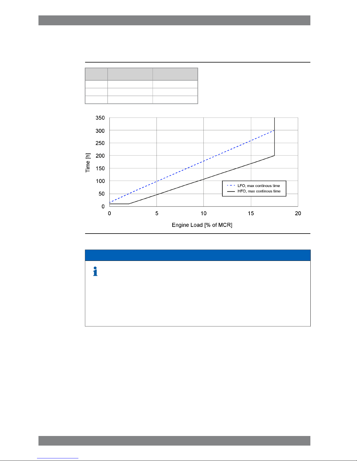
2.3 Operation at low load and idling
Table 2-1 Idling and low load operation restrictions
HFO, max continous
time [h]
LFO, max continous
time [h]
Load
10150%
10502%
20030017.5%
Fig 2-4 Low load operating restrictions
NOTE
Above 17.5% load there is no additional restriction from low load operation.1)
Duration of low load only applies if charge air temp in receiver is at:2)
- LFO: 35C or above
- HFO: 45C or above
High load running (minimum 70%) is to be followed for a minimum of 60 minutes to clean up the engine
after maximum allowed low load running time has been reached.
3)
2.4 Low air temperature
In cold conditions the following minimum inlet air temperatures apply:
● Min 5ºC
For lower suction air temperatures engines shall be configured for arctic operation.
For further guidelines, see chapter Combustion air system design.
2-4 Wärtsilä 31 Product Guide - a1 - 18 October 2016
Wärtsilä 31 Product Guide2. Operating Ranges
Page 15
3. Technical Data
3.1 Wärtsilä 8V31
ME
IMO Tier 2
AUX
IMO Tier 2
AUX
IMO Tier 2
DE
IMO Tier 2
DE
IMO Tier 2
Wärtsilä 8V31
750
610
750
610
720
590
750
610
720
590
RPM
kW/cyl
Engine speed
Cylinder output
48804880472048804720kWEngine output
3.013.013.033.013.03MPaMean effective pressure
Combustion air system (Note 1)
8.638.638.328.638.32kg/sFlow at 100% load
4545454545°CTemperature at turbocharger intake, max.
6565656565°CAir temperature after air cooler (TE 601)
Exhaust gas system (Note 2)
8.888.888.568.888.56kg/sFlow at 100% load
7.527.67.287.67.28kg/sFlow at 85% load
6.486.86.566.86.56kg/sFlow at 75% load
4.565.24.965.24.96kg/sFlow at 50% load
273273275273275°CTemperature after turbocharger, 100% load (TE 517)
277275277275277°CTemperature after turbocharger, 85% load (TE 517)
295282284282284°CTemperature after turbocharger, 75% load (TE 517)
320286288286288°CTemperature after turbocharger, 50% load (TE 517)
5.05.05.05.05.0kPaBackpressure, max.
705705693705693
mmCalculated pipe diameter for 35m/s
Heat balance (Note 3)
494494460494460kWJacket water, HT-circuit
926926858926858kWCharge air, HT-circuit
12301230119512301195kWCharge air, LT-circuit
522522487522487kWLubricating oil, LT-circuit
137137131137131kWRadiation
For optional engineversions heat balances may differ
Fuel system (Note 4)
1000±1001000±1001000±1001000±1001000±100kPaPressure before injection pumps (PT 101)
60.060.060.060.060.0m3/hEngine driven pump capacity (MDF only)
16...2416...2416...2416...2416...24cStHFO viscosity before engine
140140140140140°CHFO temperature before engine, max. (TE 101)
2.02.02.02.02.0cStMDF viscosity, min
4545454545°CMDF temperature before engine, max. (TE 101)
174.4174.9173.9174.4173.4
g/kWhFuel consumption at 100% load, HFO
171.6172.0171.1171.6170.6
g/kWhFuel consumption at 85% load, HFO
171.6174.0173.0173.5172.5
g/kWhFuel consumption at 75% load, HFO
178.5183.8182.8183.3182.3
g/kWhFuel consumption at 50% load, HFO
Wärtsilä 31 Product Guide - a1 - 18 October 2016 3-1
3. Technical DataWärtsilä 31 Product Guide
Page 16

ME
IMO Tier 2
AUX
IMO Tier 2
AUX
IMO Tier 2
DE
IMO Tier 2
DE
IMO Tier 2
Wärtsilä 8V31
750
610
750
610
720
590
750
610
720
590
RPM
kW/cyl
Engine speed
Cylinder output
173.5174.0173.0173.5172.5
g/kWhFuel consumption at 100% load, MDF
170.6171.1170.1170.6169.7
g/kWhFuel consumption at 85% load, MDF
170.6173.0172.0172.5171.6
g/kWhFuel consumption at 75% load, MDF
176.6181.9180.9181.4180.4
g/kWhFuel consumption at 50% load, MDF
17.717.717.017.717.0
kg/hClean leak fuel quantity, MDF at 100% load
3.63.63.43.63.4
kg/hClean leak fuel quantity, HFO at 100% load
Lubricating oil system
420420420420420
kPaPressure before bearings, nom. (PT 201)
4040404040
kPaSuction ability main pump, including pipe loss, max.
6060606060
kPaPriming pressure, nom. (PT 201)
3535353535
kPaSuction ability priming pump, including pipeloss, max.
7070707070
°CTemperature before bearings, nom. (TE 201)
8282828282
°CTemperature after engine, approx.
144130125130125
m³/hPump capacity (main), engine driven
100100100100100
m³/hPump capacity (main), stand-by
20.0 / 20.020.0 / 20.020.0 / 20.020.0 / 20.020.0 / 20.0m³/hPriming pump capacity, 50Hz/60Hz
2.542.542.542.542.54
m³Oil volume, wet sump, nom.
6.66.66.46.66.4
m³Oil volume in separate system oil tank, nom.
0.450.450.450.450.45
g/kWhOil consumption (100% load), approx.
19601960196019601960l/minCrankcase ventilation flow rate at full load
0.10.10.10.10.1kPaCrankcase ventilation backpressure, max.
6.0...6.86.0...6.86.0...6.86.0...6.86.0...6.8litersOil volume in turning device
Cooling water system
High temperature cooling water system
358 + stat-
ic
358 + stat-
ic
358 + stat-
ic
358 + stat-
ic
358 + stat-
ic
kPaPressure at engine, after pump, nom. (PT 401)
600600600600600
kPaPressure at engine, after pump, max. (PT 401)
8383838383
°CTemperature before cylinders, approx. (TE 401)
9696969696°CHT-water out from engine, nom (TE432)
8080808080
m³/hCapacity of engine driven pump, nom.
210210210210210kPaPressure drop over engine, total
100100100100100
kPaPressure drop in external system, max.
70...15070...15070...15070...15070...150kPaPressure from expansion tank
0.6030.6030.6030.6030.603
m³Water volume in engine
Low temperature cooling water system
25 ... 3825 ... 3825 ... 3825 ... 3825 ... 38°CTemperature before engine (TE 451)
8080808080
m³/hCapacity of engine driven pump, nom.
4141414141
kPaPressure drop over charge air cooler (one-stage)
3-2 Wärtsilä 31 Product Guide - a1 - 18 October 2016
Wärtsilä 31 Product Guide3. Technical Data
Page 17
ME
IMO Tier 2
AUX
IMO Tier 2
AUX
IMO Tier 2
DE
IMO Tier 2
DE
IMO Tier 2
Wärtsilä 8V31
750
610
750
610
720
590
750
610
720
590
RPM
kW/cyl
Engine speed
Cylinder output
110110110110110
kPaPressure drop over charge air cooler (two-stage)
115115115115115
kPaPressure drop over oil cooler
100100100100100
kPaPressure drop in external system, max.
70 ... 15070 ... 15070 ... 15070 ... 15070 ... 150kPaPressure from expansion tank
Starting air system
30003000300030003000
kPaPressure, nom.
15001500150015001500
kPaPressure at engine during start, min. (20°C)
30003000300030003000
kPaPressure, max.
16001600160016001600
kPaLow pressure limit in air vessels
4.94.94.94.94.9
Nm
3
Air consumption per start
Notes:
At ISO 15550 conditions (ambient air temperature 25°C, LT-water 25°C) and 100% load. Flow tolerance 5%.Note 1
At ISO 15550 conditions (ambient air temperature 25°C, LT-water 25°C). Flow tolerance 5% and temperature tolerance
10°C.
Note 2
At ISO 15550 conditions (ambient air temperature 25°C, LT-water 25°C) and 100% load. Tolerance for cooling water heat
10%, tolerance for radiation heat 20%. Fouling factors and a margin to be taken into account when dimensioning heat
exchangers. In arctic option charge air coolers in LT circuit.
Note 3
At ambient conditions according to ISO 15550.Lower calorific value 42 700 kJ/kg. With engine driven pumps (two cooling
water + one lubricating oil pump). Tolerance 5%.
Note 4
ME = Engine driving propeller, variable speed
AE = Auxiliary engine driving generator
DE = Diesel-Electric engine driving generator
Subject to revision without notice.
Wärtsilä 31 Product Guide - a1 - 18 October 2016 3-3
3. Technical DataWärtsilä 31 Product Guide
Page 18

3.2 Wärtsilä 10V31
ME
IMO Tier 2
AUX
IMO Tier 2
AUX
IMO Tier 2
DE
IMO Tier 2
DE
IMO Tier 2
Wärtsilä 10V31
750
610
750
610
720
590
750
610
720
590
RPM
kW/cyl
Engine speed
Cylinder output
61006100590061005900kWEngine output
3.013.013.033.013.03MPaMean effective pressure
Combustion air system (Note 1)
10.7910.7910.410.7910.4kg/sFlow at 100% load
4545454545°CTemperature at turbocharger intake, max.
6565656565°CAir temperature after air cooler (TE 601)
Exhaust gas system (Note 2)
11.111.110.711.110.7kg/sFlow at 100% load
9.49.59.19.59.1kg/sFlow at 85% load
8.18.58.28.58.2kg/sFlow at 75% load
5.76.56.26.56.2kg/sFlow at 50% load
273273275273275°CTemperature after turbocharger, 100% load (TE 517)
277275277275277°CTemperature after turbocharger, 85% load (TE 517)
295282284282284°CTemperature after turbocharger, 75% load (TE 517)
320286288286288°CTemperature after turbocharger, 50% load (TE 517)
5.05.05.05.05.0kPaBackpressure, max.
788788775788775
mmCalculated pipe diameter for 35m/s
Heat balance (Note 3)
618618575618575kWJacket water, HT-circuit
11571157107311571073kWCharge air, HT-circuit
15371537149415371494kWCharge air, LT-circuit
653653609653609kWLubricating oil, LT-circuit
171171164171164kWRadiation
For optional engineversions heat balances may differ
Fuel system (Note 4)
1000±1001000±1001000±1001000±1001000±100kPaPressure before injection pumps (PT 101)
60.060.060.060.060.0m3/hEngine driven pump capacity (MDF only)
16...2416...2416...2416...2416...24cStHFO viscosity before engine
140140140140140°CHFO temperature before engine, max. (TE 101)
2.02.02.02.02.0cStMDF viscosity, min
4545454545°CMDF temperature before engine, max. (TE 101)
174.4174.9174.0174.4173.5
g/kWhFuel consumption at 100% load, HFO
171.6172.0171.1171.6170.6
g/kWhFuel consumption at 85% load, HFO
171.6174.0173.0173.5172.5
g/kWhFuel consumption at 75% load, HFO
178.5183.8182.8183.3182.3
g/kWhFuel consumption at 50% load, HFO
173.5174.0173.0173.5172.5
g/kWhFuel consumption at 100% load, MDF
170.6171.1170.1170.6169.7
g/kWhFuel consumption at 85% load, MDF
170.6173.0172.0172.5171.6
g/kWhFuel consumption at 75% load, MDF
3-4 Wärtsilä 31 Product Guide - a1 - 18 October 2016
Wärtsilä 31 Product Guide3. Technical Data
Page 19

ME
IMO Tier 2
AUX
IMO Tier 2
AUX
IMO Tier 2
DE
IMO Tier 2
DE
IMO Tier 2
Wärtsilä 10V31
750
610
750
610
720
590
750
610
720
590
RPM
kW/cyl
Engine speed
Cylinder output
176.6181.9180.9181.4180.4
g/kWhFuel consumption at 50% load, MDF
22.122.121.322.121.2
kg/hClean leak fuel quantity, MDF at 100% load
4.44.54.34.44.3
kg/hClean leak fuel quantity, HFO at 100% load
Lubricating oil system
420420420420420
kPaPressure before bearings, nom. (PT 201)
4040404040
kPaSuction ability main pump, including pipe loss, max.
6060606060
kPaPriming pressure, nom. (PT 201)
3535353535
kPaSuction ability priming pump, including pipeloss, max.
7070707070
°CTemperature before bearings, nom. (TE 201)
8282828282
°CTemperature after engine, approx.
144130125130125
m³/hPump capacity (main), engine driven
120120120120120
m³/hPump capacity (main), stand-by
24.0 / 24.024.0 / 24.024.0 / 24.024.0 / 24.024.0 / 24.0m³/hPriming pump capacity, 50Hz/60Hz
3.03.03.03.03.0
m³Oil volume, wet sump, nom.
8.28.28.08.28.0
m³Oil volume in separate system oil tank, nom.
0.450.450.450.450.45
g/kWhOil consumption (100% load), approx.
24502450245024502450l/minCrankcase ventilation flow rate at full load
0.10.10.10.10.1kPaCrankcase ventilation backpressure, max.
6.0...6.86.0...6.86.0...6.86.0...6.86.0...6.8litersOil volume in turning device
Cooling water system
High temperature cooling water system
382 + stat-
ic
382 + stat-
ic
382 + stat-
ic
382 + stat-
ic
382 + stat-
ic
kPaPressure at engine, after pump, nom. (PT 401)
600600600600600
kPaPressure at engine, after pump, max. (PT 401)
8383838383
°CTemperature before cylinders, approx. (TE 401)
9696969696°CHT-water out from engine, nom (TE432)
9090909090
m³/hCapacity of engine driven pump, nom.
210210210210210kPaPressure drop over engine, total
100100100100100
kPaPressure drop in external system, max.
70...15070...15070...15070...15070...150kPaPressure from expansion tank
0.6420.6420.6420.6420.642
m³Water volume in engine
Low temperature cooling water system
25 ... 3825 ... 3825 ... 3825 ... 3825 ... 38°CTemperature before engine (TE 451)
9090909090
m³/hCapacity of engine driven pump, nom.
00000
kPaPressure drop over charge air cooler
4141414141
kPaPressure drop over charge air cooler (one-stage)
110110110110110
kPaPressure drop over charge air cooler (two-stage)
100100100100100
kPaPressure drop in external system, max.
Wärtsilä 31 Product Guide - a1 - 18 October 2016 3-5
3. Technical DataWärtsilä 31 Product Guide
Page 20
ME
IMO Tier 2
AUX
IMO Tier 2
AUX
IMO Tier 2
DE
IMO Tier 2
DE
IMO Tier 2
Wärtsilä 10V31
750
610
750
610
720
590
750
610
720
590
RPM
kW/cyl
Engine speed
Cylinder output
70 ... 15070 ... 15070 ... 15070 ... 15070 ... 150kPaPressure from expansion tank
Starting air system
30003000300030003000
kPaPressure, nom.
15001500150015001500
kPaPressure at engine during start, min. (20°C)
30003000300030003000
kPaPressure, max.
16001600160016001600
kPaLow pressure limit in air vessels
5.15.15.15.15.1
Nm
3
Air consumption per start
Notes:
At ISO 15550 conditions (ambient air temperature 25°C, LT-water 25°C) and 100% load. Flow tolerance 5%.Note 1
At ISO 15550 conditions (ambient air temperature 25°C, LT-water 25°C). Flow tolerance 5% and temperature tolerance
10°C.
Note 2
At ISO 15550 conditions (ambient air temperature 25°C, LT-water 25°C) and 100% load. Tolerance for cooling water heat
10%, tolerance for radiation heat 20%. Fouling factors and a margin to be taken into account when dimensioning heat
exchangers. In arctic option charge air coolers in LT circuit.
Note 3
At ambient conditions according to ISO 15550.Lower calorific value 42 700 kJ/kg. With engine driven pumps (two cooling
water + one lubricating oil pump). Tolerance 5%.
Note 4
ME = Engine driving propeller, variable speed
AE = Auxiliary engine driving generator
DE = Diesel-Electric engine driving generator
Subject to revision without notice.
3-6 Wärtsilä 31 Product Guide - a1 - 18 October 2016
Wärtsilä 31 Product Guide3. Technical Data
Page 21

3.3 Wärtsilä 12V31
ME
IMO Tier 2
AUX
IMO Tier 2
AUX
IMO Tier 2
DE
IMO Tier 2
DE
IMO Tier 2
Wärtsilä 12V31
750
610
750
610
720
590
750
610
720
590
RPM
kW/cyl
Engine speed
Cylinder output
73207320708073207080kWEngine output
3.013.013.033.013.03MPaMean effective pressure
Combustion air system (Note 1)
12.9512.9512.4812.9512.48kg/sFlow at 100% load
4545454545°CTemperature at turbocharger intake, max.
6565656565°CAir temperature after air cooler (TE 601)
Exhaust gas system (Note 2)
13.3213.3212.8413.3212.84kg/sFlow at 100% load
11.2811.410.9211.410.92kg/sFlow at 85% load
9.7210.29.8410.29.84kg/sFlow at 75% load
6.847.87.447.87.44kg/sFlow at 50% load
273273275273275°CTemperature after turbocharger, 100% load (TE 517)
277275277275277°CTemperature after turbocharger, 85% load (TE 517)
295282284282284°CTemperature after turbocharger, 75% load (TE 517)
320286288286288°CTemperature after turbocharger, 50% load (TE 517)
5.05.05.05.05.0kPaBackpressure, max.
863863849863849
mmCalculated pipe diameter for 35m/s
Heat balance (Note 3)
742742690742690kWJacket water, HT-circuit
13881388128813881288kWCharge air, HT-circuit
18441844179318441793kWCharge air, LT-circuit
784784731784731kWLubricating oil, LT-circuit
205205197205197kWRadiation
For optional engine versions heat balances may differ
Fuel system (Note 4)
1000±1001000±1001000±1001000±1001000±100kPaPressure before injection pumps (PT 101)
120.0120.0120.0120.0120.0m3/hEngine driven pump capacity (MDF only)
16...2416...2416...2416...2416...24cStHFO viscosity before engine
140140140140140°CHFO temperature before engine, max. (TE 101)
2.02.02.02.02.0cStMDF viscosity, min
4545454545°CMDF temperature before engine, max. (TE 101)
174.4174.9174.0174.4173.5
g/kWhFuel consumption at 100% load, HFO
171.6172.0171.1171.6170.6
g/kWhFuel consumption at 85% load, HFO
171.6174.0173.0173.5172.5
g/kWhFuel consumption at 75% load, HFO
178.5183.8182.8183.3182.3
g/kWhFuel consumption at 50% load, HFO
173.5174.0173.0173.5172.5
g/kWhFuel consumption at 100% load, MDF
170.6171.1170.1170.6169.7
g/kWhFuel consumption at 85% load, MDF
170.6173.0172.0172.5171.6
g/kWhFuel consumption at 75% load, MDF
Wärtsilä 31 Product Guide - a1 - 18 October 2016 3-7
3. Technical DataWärtsilä 31 Product Guide
Page 22

ME
IMO Tier 2
AUX
IMO Tier 2
AUX
IMO Tier 2
DE
IMO Tier 2
DE
IMO Tier 2
Wärtsilä 12V31
750
610
750
610
720
590
750
610
720
590
RPM
kW/cyl
Engine speed
Cylinder output
176.6181.9180.9181.4180.4
g/kWhFuel consumption at 50% load, MDF
26.526.625.626.525.5
kg/hClean leak fuel quantity, MDF at 100% load
5.35.35.15.35.1
kg/hClean leak fuel quantity, HFO at 100% load
Lubricating oil system
420420420420420
kPaPressure before bearings, nom. (PT 201)
4040404040
kPaSuction ability main pump, including pipe loss, max.
6060606060
kPaPriming pressure, nom. (PT 201)
3535353535
kPaSuction ability priming pump, including pipeloss, max.
7070707070
°CTemperature before bearings, nom. (TE 201)
8282828282
°CTemperature after engine, approx.
170144138144138
m³/hPump capacity (main), engine driven
137137137137137
m³/hPump capacity (main), stand-by
29.0 / 29.029.0 / 29.029.0 / 29.029.0 / 29.029.0 / 29.0m³/hPriming pump capacity, 50Hz/60Hz
3.33.33.33.33.3
m³Oil volume, wet sump, nom.
9.99.99.69.99.6
m³Oil volume in separate system oil tank, nom.
0.450.450.450.450.45
g/kWhOil consumption (100% load), approx.
29402940294029402940l/minCrankcase ventilation flow rate at full load
0.10.10.10.10.1kPaCrankcase ventilation backpressure, max.
6.0...6.86.0...6.86.0...6.86.0...6.86.0...6.8litersOil volume in turning device
Cooling water system
High temperature cooling water system
363 + stat-
ic
363 + stat-
ic
363 + stat-
ic
363 + stat-
ic
363 + stat-
ic
kPaPressure at engine, after pump, nom. (PT 401)
600600600600600
kPaPressure at engine, after pump, max. (PT 401)
8383838383
°CTemperature before cylinders, approx. (TE 401)
9696969696°CHT-water out from engine, nom (TE432)
110110110110110
m³/hCapacity of engine driven pump, nom.
210210210210210kPaPressure drop over engine, total
100100100100100
kPaPressure drop in external system, max.
70...15070...15070...15070...15070...150kPaPressure from expansion tank
m³Water volume in engine
Low temperature cooling water system
25 ... 3825 ... 3825 ... 3825 ... 3825 ... 38°CTemperature before engine (TE 451)
110110110110110
m³/hCapacity of engine driven pump, nom.
4141414141
kPaPressure drop over charge air cooler (one-stage)
110110110110110
kPaPressure drop over charge air cooler (two-stage)
115115115115115
kPaPressure drop over oil cooler
100100100100100
kPaPressure drop in external system, max.
3-8 Wärtsilä 31 Product Guide - a1 - 18 October 2016
Wärtsilä 31 Product Guide3. Technical Data
Page 23
ME
IMO Tier 2
AUX
IMO Tier 2
AUX
IMO Tier 2
DE
IMO Tier 2
DE
IMO Tier 2
Wärtsilä 12V31
750
610
750
610
720
590
750
610
720
590
RPM
kW/cyl
Engine speed
Cylinder output
70 ... 15070 ... 15070 ... 15070 ... 15070 ... 150kPaPressure from expansion tank
Starting air system
30003000300030003000
kPaPressure, nom.
15001500150015001500
kPaPressure at engine during start, min. (20°C)
30003000300030003000
kPaPressure, max.
16001600160016001600
kPaLow pressure limit in air vessels
5.45.45.45.45.4
Nm
3
Air consumption per start
Notes:
At ISO 15550 conditions (ambient air temperature 25°C, LT-water 25°C) and 100% load. Flow tolerance 5%.Note 1
At ISO 15550 conditions (ambient air temperature 25°C, LT-water 25°C). Flow tolerance 5% and temperature tolerance
10°C.
Note 2
At ISO 15550 conditions (ambient air temperature 25°C, LT-water 25°C) and 100% load. Tolerance for cooling water heat
10%, tolerance for radiation heat 20%. Fouling factors and a margin to be taken into account when dimensioning heat
exchangers. In arctic option charge air coolers in LT circuit.
Note 3
At ambient conditions according to ISO 15550.Lower calorific value 42 700 kJ/kg. With engine driven pumps (two cooling
water + one lubricating oil pump). Tolerance 5%.
Note 4
ME = Engine driving propeller, variable speed
AE = Auxiliary engine driving generator
DE = Diesel-Electric engine driving generator
Subject to revision without notice.
Wärtsilä 31 Product Guide - a1 - 18 October 2016 3-9
3. Technical DataWärtsilä 31 Product Guide
Page 24
3.4 Wärtsilä 14V31
ME
IMO Tier 2
AUX
IMO Tier 2
AUX
IMO Tier 2
DE
IMO Tier 2
DE
IMO Tier 2
Wärtsilä 14V31
750
610
750
610
720
590
750
610
720
590
RPM
kW/cyl
Engine speed
Cylinder output
85408540826085408260kWEngine output
3.013.013.033.013.03MPaMean effective pressure
Combustion air system (Note 1)
15.1115.1114.5615.1114.56kg/sFlow at 100% load
4545454545°CTemperature at turbocharger intake, max.
6565656565°CAir temperature after air cooler (TE 601)
Exhaust gas system (Note 2)
15.5415.5414.9815.5414.98kg/sFlow at 100% load
13.1613.312.7413.312.74kg/sFlow at 85% load
11.3411.911.4811.911.48kg/sFlow at 75% load
7.989.18.689.18.68kg/sFlow at 50% load
273273275273275°CTemperature after turbocharger, 100% load (TE 517)
277275277275277°CTemperature after turbocharger, 85% load (TE 517)
295282284282284°CTemperature after turbocharger, 75% load (TE 517)
320286288286288°CTemperature after turbocharger, 50% load (TE 517)
5.05.05.05.05.0kPaBackpressure, max.
933933917933917
mmCalculated pipe diameter for 35m/s
Heat balance (Note 3)
865865805865805kWJacket water, HT-circuit
16201620150216201502kWCharge air, HT-circuit
21522152209221522092kWCharge air, LT-circuit
914914853914853kWLubricating oil, LT-circuit
239239230239230kWRadiation
For optional engineversions heat balances may differ
Fuel system (Note 4)
1000±1001000±1001000±1001000±1001000±100kPaPressure before injection pumps (PT 101)
120.0120.0120.0120.0120.0m3/hEngine driven pump capacity (MDF only)
16...2416...2416...2416...2416...24cStHFO viscosity before engine
140140140140140°CHFO temperature before engine, max. (TE 101)
2.02.02.02.02.0cStMDF viscosity, min
4545454545°CMDF temperature before engine, max. (TE 101)
174.4174.9174.0174.4173.5
g/kWhFuel consumption at 100% load, HFO
171.6172.0171.1171.6170.6
g/kWhFuel consumption at 85% load, HFO
171.6174.0173.0173.5172.5
g/kWhFuel consumption at 75% load, HFO
178.5183.8182.8183.3182.3
g/kWhFuel consumption at 50% load, HFO
173.5174.0173.0173.5172.5
g/kWhFuel consumption at 100% load, MDF
170.6171.1170.1170.6169.7
g/kWhFuel consumption at 85% load, MDF
170.6173.0172.0172.5171.6
g/kWhFuel consumption at 75% load, MDF
3-10 Wärtsilä 31 Product Guide - a1 - 18 October 2016
Wärtsilä 31 Product Guide3. Technical Data
Page 25

ME
IMO Tier 2
AUX
IMO Tier 2
AUX
IMO Tier 2
DE
IMO Tier 2
DE
IMO Tier 2
Wärtsilä 14V31
750
610
750
610
720
590
750
610
720
590
RPM
kW/cyl
Engine speed
Cylinder output
176.6181.9180.9181.4180.4
g/kWhFuel consumption at 50% load, MDF
30.931.029.830.929.7
kg/hClean leak fuel quantity, MDF at 100% load
6.26.26.06.26.0
kg/hClean leak fuel quantity, HFO at 100% load
Lubricating oil system
420420420420420
kPaPressure before bearings, nom. (PT 201)
4040404040
kPaSuction ability main pump, including pipe loss, max.
6060606060
kPaPriming pressure, nom. (PT 201)
3535353535
kPaSuction ability priming pump, including pipeloss, max.
7070707070
°CTemperature before bearings, nom. (TE 201)
8282828282
°CTemperature after engine, approx.
189170164170164
m³/hPump capacity (main), engine driven
160160160160160
m³/hPump capacity (main), stand-by
34.0 / 34.034.0 / 34.034.0 / 34.034.0 / 34.034.0 / 34.0m³/hPriming pump capacity, 50Hz/60Hz
3.853.853.853.853.85
m³Oil volume, wet sump, nom.
11.511.511.211.511.2
m³Oil volume in separate system oil tank, nom.
0.450.450.450.450.45
g/kWhOil consumption (100% load), approx.
34303430343034303430l/minCrankcase ventilation flow rate at full load
0.10.10.10.10.1kPaCrankcase ventilation backpressure, max.
6.0...6.86.0...6.86.0...6.86.0...6.86.0...6.8litersOil volume in turning device
Cooling water system
High temperature cooling water system
397 + stat-
ic
397 + stat-
ic
397 + stat-
ic
397 + stat-
ic
397 + stat-
ic
kPaPressure at engine, after pump, nom. (PT 401)
600600600600600
kPaPressure at engine, after pump, max. (PT 401)
8383838383
°CTemperature before cylinders, approx. (TE 401)
9696969696°CHT-water out from engine, nom (TE432)
189189130189130
m³/hCapacity of engine driven pump, nom.
210210210210210kPaPressure drop over engine, total
100100100100100
kPaPressure drop in external system, max.
70...15070...15070...15070...15070...150kPaPressure from expansion tank
m³Water volume in engine
Low temperature cooling water system
25 ... 3825 ... 3825 ... 3825 ... 3825 ... 38°CTemperature before engine (TE 451)
130130130130130
m³/hCapacity of engine driven pump, nom.
4141414141
kPaPressure drop over charge air cooler (one-stage)
110110110110110
kPaPressure drop over charge air cooler (two-stage)
115115115115115
kPaPressure drop over oil cooler
100100100100100
kPaPressure drop in external system, max.
Wärtsilä 31 Product Guide - a1 - 18 October 2016 3-11
3. Technical DataWärtsilä 31 Product Guide
Page 26

ME
IMO Tier 2
AUX
IMO Tier 2
AUX
IMO Tier 2
DE
IMO Tier 2
DE
IMO Tier 2
Wärtsilä 14V31
750
610
750
610
720
590
750
610
720
590
RPM
kW/cyl
Engine speed
Cylinder output
70 ... 15070 ... 15070 ... 15070 ... 15070 ... 150kPaPressure from expansion tank
Starting air system
30003000300030003000
kPaPressure, nom.
15001500150015001500
kPaPressure at engine during start, min. (20°C)
30003000300030003000
kPaPressure, max.
16001600160016001600
kPaLow pressure limit in air vessels
5.85.85.85.85.8
Nm
3
Air consumption per start
Notes:
At ISO 15550 conditions (ambient air temperature 25°C, LT-water 25°C) and 100% load. Flow tolerance 5%.Note 1
At ISO 15550 conditions (ambient air temperature 25°C, LT-water 25°C). Flow tolerance 5% and temperature tolerance
10°C.
Note 2
At ISO 15550 conditions (ambient air temperature 25°C, LT-water 25°C) and 100% load. Tolerance for cooling water heat
10%, tolerance for radiation heat 20%. Fouling factors and a margin to be taken into account when dimensioning heat
exchangers. In arctic option charge air coolers in LT circuit.
Note 3
At ambient conditions according to ISO 15550.Lower calorific value 42 700 kJ/kg. With engine driven pumps (two cooling
water + one lubricating oil pump). Tolerance 5%.
Note 4
ME = Engine driving propeller, variable speed
AE = Auxiliary engine driving generator
DE = Diesel-Electric engine driving generator
Subject to revision without notice.
3-12 Wärtsilä 31 Product Guide - a1 - 18 October 2016
Wärtsilä 31 Product Guide3. Technical Data
Page 27
3.5 Wärtsilä 16V31
ME
IMO Tier 2
AUX
IMO Tier 2
AUX
IMO Tier 2
DE
IMO Tier 2
DE
IMO Tier 2
Wärtsilä 16V31
750
610
750
610
720
590
750
610
720
590
RPM
kW/cyl
Engine speed
Cylinder output
97609760944097609440kWEngine output
3.013.013.033.013.03MPaMean effective pressure
Combustion air system (Note 1)
17.2717.2716.6517.2716.65kg/sFlow at 100% load
4545454545°CTemperature at turbocharger intake, max.
6565656565°CAir temperature after air cooler (TE 601)
Exhaust gas system (Note 2)
17.7617.7617.1217.7617.12kg/sFlow at 100% load
15.0415.214.5615.214.56kg/sFlow at 85% load
12.9613.613.1213.613.12kg/sFlow at 75% load
9.1210.49.9210.49.92kg/sFlow at 50% load
273273275273275°CTemperature after turbocharger, 100% load (TE 517)
277275277275277°CTemperature after turbocharger, 85% load (TE 517)
295282284282284°CTemperature after turbocharger, 75% load (TE 517)
320286288286288°CTemperature after turbocharger, 50% load (TE 517)
5.05.05.05.05.0kPaBackpressure, max.
997997981997981
mmCalculated pipe diameter for 35m/s
Heat balance (Note 3)
989989920989920kWJacket water, HT-circuit
18511851171718511717kWCharge air, HT-circuit
24592459239024592390kWCharge air, LT-circuit
104510459741045974kWLubricating oil, LT-circuit
274274262274262kWRadiation
For optional engineversions heat balances may differ
Fuel system (Note 4)
1000±1001000±1001000±1001000±1001000±100kPaPressure before injection pumps (PT 101)
120.0120.0120.0120.0120.0m3/hEngine driven pump capacity (MDF only)
16...2416...2416...2416...2416...24cStHFO viscosity before engine
140140140140140°CHFO temperature before engine, max. (TE 101)
2.02.02.02.02.0cStMDF viscosity, min
4545454545°CMDF temperature before engine, max. (TE 101)
174.4174.9174.0174.4173.5
g/kWhFuel consumption at 100% load, HFO
171.7172.0171.1171.6170.6
g/kWhFuel consumption at 85% load, HFO
171.7174.0173.0173.5172.5
g/kWhFuel consumption at 75% load, HFO
178.6183.8182.8183.3182.3
g/kWhFuel consumption at 50% load, HFO
173.5174.0173.0173.5172.5
g/kWhFuel consumption at 100% load, MDF
170.7171.1170.1170.6169.7
g/kWhFuel consumption at 85% load, MDF
170.7173.0172.0172.5171.6
g/kWhFuel consumption at 75% load, MDF
Wärtsilä 31 Product Guide - a1 - 18 October 2016 3-13
3. Technical DataWärtsilä 31 Product Guide
Page 28
ME
IMO Tier 2
AUX
IMO Tier 2
AUX
IMO Tier 2
DE
IMO Tier 2
DE
IMO Tier 2
Wärtsilä 16V31
750
610
750
610
720
590
750
610
720
590
RPM
kW/cyl
Engine speed
Cylinder output
176.7181.9180.9181.4180.4
g/kWhFuel consumption at 50% load, MDF
35.335.434.135.334.0
kg/hClean leak fuel quantity, MDF at 100% load
7.17.16.97.16.8
kg/hClean leak fuel quantity, HFO at 100% load
Lubricating oil system
420420420420420
kPaPressure before bearings, nom. (PT 201)
4040404040
kPaSuction ability main pump, including pipe loss, max.
6060606060
kPaPriming pressure, nom. (PT 201)
3535353535
kPaSuction ability priming pump, including pipeloss, max.
7070707070
°CTemperature before bearings, nom. (TE 201)
8282828282
°CTemperature after engine, approx.
223189182189182
m³/hPump capacity (main), engine driven
176176176176176
m³/hPump capacity (main), stand-by
38.0 / 38.038.0 / 38.038.0 / 38.038.0 / 38.038.0 / 38.0m³/hPriming pump capacity, 50Hz/60Hz
4.44.44.44.44.4
m³Oil volume, wet sump, nom.
13.213.212.713.212.7
m³Oil volume in separate system oil tank, nom.
0.450.450.450.450.45
g/kWhOil consumption (100% load), approx.
39203920392039203920l/minCrankcase ventilation flow rate at full load
0.10.10.10.10.1kPaCrankcase ventilation backpressure, max.
6.0...6.86.0...6.86.0...6.86.0...6.86.0...6.8litersOil volume in turning device
Cooling water system
High temperature cooling water system
373 + stat-
ic
373 + stat-
ic
373 + stat-
ic
373 + stat-
ic
373 + stat-
ic
kPaPressure at engine, after pump, nom. (PT 401)
600600600600600
kPaPressure at engine, after pump, max. (PT 401)
8383838383
°CTemperature before cylinders, approx. (TE 401)
9696969696°CHT-water out from engine, nom (TE432)
150150150150150
m³/hCapacity of engine driven pump, nom.
210210210210210kPaPressure drop over engine, total
100100100100100
kPaPressure drop in external system, max.
70...15070...15070...15070...15070...150kPaPressure from expansion tank
m³Water volume in engine
Low temperature cooling water system
25 ... 3825 ... 3825 ... 3825 ... 3825 ... 38°CTemperature before engine (TE 451)
150150150150150
m³/hCapacity of engine driven pump, nom.
4141414141
kPaPressure drop over charge air cooler (one-stage)
110110110110110
kPaPressure drop over charge air cooler (two-stage)
115115115115115
kPaPressure drop over oil cooler
100100100100100
kPaPressure drop in external system, max.
3-14 Wärtsilä 31 Product Guide - a1 - 18 October 2016
Wärtsilä 31 Product Guide3. Technical Data
Page 29

ME
IMO Tier 2
AUX
IMO Tier 2
AUX
IMO Tier 2
DE
IMO Tier 2
DE
IMO Tier 2
Wärtsilä 16V31
750
610
750
610
720
590
750
610
720
590
RPM
kW/cyl
Engine speed
Cylinder output
70 ... 15070 ... 15070 ... 15070 ... 15070 ... 150kPaPressure from expansion tank
Starting air system
30003000300030003000
kPaPressure, nom.
15001500150015001500
kPaPressure at engine during start, min. (20°C)
30003000300030003000
kPaPressure, max.
16001600160016001600
kPaLow pressure limit in air vessels
6.36.36.36.36.3
Nm
3
Air consumption per start
Notes:
At ISO 15550 conditions (ambient air temperature 25°C, LT-water 25°C) and 100% load. Flow tolerance 5%.Note 1
At ISO 15550 conditions (ambient air temperature 25°C, LT-water 25°C). Flow tolerance 5% and temperature tolerance
10°C.
Note 2
At ISO 15550 conditions (ambient air temperature 25°C, LT-water 25°C) and 100% load. Tolerance for cooling water heat
10%, tolerance for radiation heat 20%. Fouling factors and a margin to be taken into account when dimensioning heat
exchangers. In arctic option charge air coolers in LT circuit.
Note 3
At ambient conditions according to ISO 15550.Lower calorific value 42 700 kJ/kg. With engine driven pumps (two cooling
water + one lubricating oil pump). Tolerance 5%.
Note 4
ME = Engine driving propeller, variable speed
AE = Auxiliary engine driving generator
DE = Diesel-Electric engine driving generator
Subject to revision without notice.
Wärtsilä 31 Product Guide - a1 - 18 October 2016 3-15
3. Technical DataWärtsilä 31 Product Guide
Page 30

This page intentionally left blank
Page 31

4. Description of the Engine
4.1 Definitions
Fig 4-1 Engine definitions (V93C0028)
4.2 Main components and systems
The dimensions and weights of engines are shown in section 1.4 Dimensions and weights .
4.2.1 Engine block
The engine block, made of nodular cast iron, is cast in one piece for all cylinder numbers and
it supports the underslung crankshaft. The block has been given a stiff and durable design to
absorb internal forces and the engine can therefore also be resiliently mounted not requiring
any intermediate foundations. It incorporates water and charge air main and side channels.
Also camshaft bearing housings are incorporated in the engine block. The engines are equipped
with crankcase explosion relief valve with flame arrester.
The main bearing caps, made of nodular cast iron, are fixed with two hydraulically tensioned
screws from below. They are guided sideways and vertically by the engine block. Hydraulically
tensioned horizontal side screws at the lower guiding provide a very rigid crankshaft bearing
assembly.
A hydraulic jack, supported in the oil sump, offers the possibility to lower and lift the main
bearing caps, e.g. when inspecting the bearings. Lubricating oil is led to the bearings through
this jack.
The oil sump, a light welded design, is mounted on the engine block from below. The oil sump
is available in two alternative designs, wet or dry sump, depending on the type of application.
The wet oil sump includes a suction pipe to the lubricating oil pump. For wet sump there is a
main distributing pipe for lubricating oil, suction pipes and return connections for the separator.
For the dry sump there is a main distributing oil pipe for lubricating oil and drains at either end
to a separate system oil tank.
The engine holding down bolts are hydraulically tightened in order to facilitate the engine
installation to both rigid and resilient foundation.
Wärtsilä 31 Product Guide - a1 - 18 October 2016 4-1
4. Description of the EngineWärtsilä 31 Product Guide
Page 32

4.2.2 Crankshaft
Crankshaft line is built up from several pieces: crankshaft, counter weights, split camshaft
gear wheel and pumpdrive arrangement.
Crankshaft itself is forged in one piece. Both main bearings and big end bearings temperatures
are continuously monitored.
Counterweights are fitted on every web. High degree of balancing results in an even and thick
oil film for all bearings.
The connecting rods are arranged side-by-side and the diameters of the crank pins and journals
are equal irrespective of the cylinder number.
All crankshafts can be provided with torsional vibration dampers or tuning masses at the free
end of the engine, if necessary. Main features of crankshaft design: clean steel technology
minimizes the amount of slag forming elements and guarantees superior material durability.
The crankshaft alignment is always done on a thoroughly warm engine after the engine is
stopped.
4.2.3 Main bearings and big end bearings
The main bearings and the big end bearings are of tri-metal design with steel back, lead-bronze
lining and a soft running layer. The bearings are covered with a Sn-flash for corrosion protection.
Even minor form deviations can become visible on the bearing surface in the running in phase.
This has no negative influence on the bearing function. A wireless system for real-time
temperature monitoring of connecting rod big end bearings, "BEB monitoring system", is as
standard.
4.2.4 Cylinder liner
The cylinder liners are centrifugally casted of a special alloyed cast iron. The top collar of the
cylinder liner is provided with a water jacket for distributing cooling water through the cylinder
liner cooling bores. This will give an efficient control of the liner temperature.
A jet cooling nozzle inside the cylinder liner is injecting oil to the underside of the piston and
is then cooling the piston and lubricating the gudgeon pin bearing through the oil channels in
the top of the connecting rod.
4.2.5 Piston
The piston is of composite type with steel crown and nodular cast iron skirt. A piston skirt
lubricating system, featuring oil bores in a groove on the piston skirt, lubricates the piston
skirt/cylinder liner. The piston top is oil cooled by the jet cooling as mentioned above. The
piston ring grooves are hardened.
4.2.6 Piston rings
The piston ring set are located in the piston crown and consists of two directional compression
rings and one spring-loaded conformable oil scraper ring. Running face of compression rings
are chromium-ceramic-plated.
4.2.7 Cylinder head
The cross flow cylinder head is made of cast iron. The mechanical load is absorbed by a flame
plate, which together with the upper deck and the side walls form a rigid box section. There
are four hydraulically tightened cylinder head bolts. The exhaust valve seats and the flame
deck are efficiently and direct water-cooled. The valve seat rings are made of alloyed steel,
for wear resistance. All valves are hydraulic controlled with valve guides and equipped with
valve springs and rotators.
4-2 Wärtsilä 31 Product Guide - a1 - 18 October 2016
Wärtsilä 31 Product Guide4. Description of the Engine
Page 33

A small side air receiver is located in the hot box, including charge air bends with integrated
hydraulics and charge air riser pipes.
Following components are connected to the cylinder head:
● Charge air components for side receiver
● Exhaust gas pipe to exhaust system
● Cooling water collar
● Quill pipe with High Pressure (HP) fuel pipe connections
4.2.8 Camshaft and valve mechanism
The cams are integrated in the drop forged shaft material. The bearing journals are made in
separate pieces, which are fitted, to the camshaft pieces by flange connections. The camshaft
bearing housings are integrated in the engine block casting and are thus completely closed.
The bearings are installed and removed by means of a hydraulic tool. The camshaft covers,
one for each cylinder, seal against the engine block with a closed O-ring profile. The valve
tappets are of piston type with self-adjustment of roller against cam to give an even distribution
of the contact pressure. Inlet and exhaust valves have a special steam coating and hard facing
on the seat surface, for long lifetime. The valve springs make the valve mechanism dynamically
stable.
The step-less valve mechanism makes it possible to control the timing of both inlet & exhaust
valves. It allows to always use a proper scavenging period. This is needed to optimize and
balance emissions, fuel consumption, operational flexibility & load taking, whilst maintaining
thermal and mechanical reliability. The design enables clearly longer maintenance interval,
due to the reduced thermal and mechanical stress on most of the components in the valve
mechanism.
4.2.9 Camshaft drive
The camshafts are driven by the crankshaft through a gear train.
4.2.10 Turbocharging and charge air cooling
The selected 2-stage turbocharging offers ideal combination of high-pressure ratios and good
efficiency both at full and part load. The turbochargers can be placed at the free end or flywheel
end of the engine. For cleaning of the turbochargers during operation there is, as standard, a
water washing device for the air (compressor) and exhaust gas (turbine) side of the LP stage
and for the exhaust gas (turbine) side of the HP stage. The water washing device is connected
to an external washing unit. The turbochargers are supplied with inboard plain bearings, which
offers easy maintenance of the cartridge from the compressor side. The turbochargers are
lubricated by engine lubricating oil with integrated connections.
An Exhaust gas Waste Gate (EWG) system controls the exhaust gas flow by-passing for both
high pressure (HP) and low pressure (LP) turbine stages. EWG is needed also in case of engines
equipped with exhaust gas after treatment based on Selective Catalytic Reaction (SCR).
By using Air Waste Gate (AWG) for bleeding air out from the charge air system, the charge air
pressure and the margin from LP compressor surging is controlled. The charge air pressure
control is used to avoid excessive charge air pressure preventing excessive firing pressure.
A step-less Air By-pass valve (ABP) system is used in all engine applications for preventing
surging of turbocharger compressors in case of rapid engine load reduction. When the ABP
valve is open part of charge air is released to the exhaust side.
The Charge Air Coolers (CAC) consist of a 2-stage type cooler (LP CAC) between the LP and
HP compressor stages and a 1-stage cooler (HP CAC) between the HP compressor stage
and the charge air receiver. The LP CAC is cooled with LT-water or in some cases by both
HT- and LT-water. The HP CAC is always cooled by LT-water. Fresh water is used for both
circuits.
Wärtsilä 31 Product Guide - a1 - 18 October 2016 4-3
4. Description of the EngineWärtsilä 31 Product Guide
Page 34

See chapter Exhaust gas & charge air systems for more information.
4.2.11 Fuel injection equipment
The fuel injection equipment and system piping are located in a hotbox, providing maximum
reliability and safety when using preheated heavy fuels. In the Wärtsilä electronic fuel injection
rate optimized nozzles system, the fuel is pressurized in the high pressure HP-pumps from
where the fuel is fed to the injection valves. The fuel system consists of different numbers of
fuel oil HP pumps, depending of the cylinder configuration, located at the engine pump cover.
From the HP pumps, high pressure pipes are connected to the cylinder heads.
A valve block is mounted at the fuel outlet pipe, including Pressure Drop and Safety Valve
(PDSV), Circulation Valve (CV) and a fuel pressure discharge volume. The PDSV acts as
mechanical safety valve and the fuel volume lowers the system pressure. The injection valves
are electronic controlled and the injection timing is pre-set in the control system software. The
injector solenoids have a own cooling system.
4.2.12 Lubricating oil system
The engine internal lubricating oil system include the engine driven lubricating oil pump, the
electrically driven prelubricating oil pump, thermostatic valve, filters and lubricating oil cooler.
The lubricating oil pumps are located in the free end of the engine, while the automatic filter,
cooler and thermostatic valve are integrated into one module.
4.2.13 Cooling water system
The fresh water cooling system is divided into a high temperature (HT) and a low temperature
(LT) circuit.
For engines operating in normal conditions the HT-water is cooling the cylinders (jacket) and
the first stage of the low pressure 2-stage charge air cooler. The LT-water is cooling the
lbricating oil cooler, the second stage of the low pressure 2-stage charge air cooler and the
high pressure 1-stage charge air cooler.
For engines operating in cold conditions the HT-water is cooling the cylinders (Jacket). A
HT-water pump is circulating the cooling water in the circuit and a thermostatic valve mounted
in the internal cooling water system, controls the outlet temperature of the circuit. The LT-circuit
is cooling the Lubricating Oil Cooler (LOC), the second stage of the Low Pressure 2-stage
charge air cooler, the High Pressure 1-stage charge air cooler and the first stage of the low
pressure 2-stage charge air cooler. An LT-thermostatic valve mounted in the external cooling
water system, controls the inlet temperature to the engine for achieving correct receiver
temperature.
4.2.14 Exhaust pipes
The exhaust manifold pipes are made of special heat resistant nodular cast iron alloy.
The complete exhaust gas system is enclosed in an insulating box consisting of easily
removable panels. Mineral wool is used as insulating material.
4.2.15 Automation system
The Wärtsilä 31 engine is equipped with an UNIC electronic control system. UNIC have
hardwired interface for control functions and a bus communication interface for alarm and
monitoring. Additionally UNIC includes fuel injection control for engines with electronic fuel
injection rate optimized nozzles.
For more information, see chapter Automation System.
4-4 Wärtsilä 31 Product Guide - a1 - 18 October 2016
Wärtsilä 31 Product Guide4. Description of the Engine
Page 35

4.3 Expected overhaul intervals and life times
The following overhaul intervals and lifetimes are for guidance only. Actual figures will be
different depending on service conditions. Expected component lifetimes have been adjusted
to match overhaul intervals.
In this list HFO is based on HFO2 specification stated in the chapter .
4.3.1 Time Between Overhaul and Expected Life Time
Table 4-1 Time Between Overhaul and Expected Life Time
Expected life time (h)
1)
Time between inspection or overhaul
(h)
Component
LFOHFOLFOHFO
Min. 96000Min. 720003200024000Piston
32000240003200024000Piston rings
128000960003200024000Cylinder liner
64000...12800048000..960003200024000Cylinder head
32000240003200024000Inlet valve
32000240003200024000Exhaust valve
64000480003200024000Main bearing
32000240003200024000Big end bearing
64000640006400064000Intermediate gear
bearings
32000320003200032000Balancing shaft
bearings
NANA80008000Injection valve
(wear parts)
24000240002400024000High Pressure fuel
pump
NOTE
1) Achieved life times very much depend on the operating conditions, average
loading of the engine, fuel quality used, fuel handling systems, performance of
maintenance etc.
4.4 Engine storage
At delivery the engine is provided with VCI coating and a tarpaulin. For storage longer than 3
months please contact Wärtsilä Finland Oy.
Wärtsilä 31 Product Guide - a1 - 18 October 2016 4-5
4. Description of the EngineWärtsilä 31 Product Guide
Page 36

This page intentionally left blank
Page 37

5. Piping Design, Treatment and Installation
This chapter provides general guidelines for the design, construction and planning of piping
systems, however, not excluding other solutions of at least equal standard. Installation related
instructions are included in the project specific instructions delivered for each installation.
Fuel, lubricating oil, fresh water and compressed air piping is usually made in seamless carbon
steel (DIN 2448) and seamless precision tubes in carbon or stainless steel (DIN 2391), exhaust
gas piping in welded pipes of corten or carbon steel (DIN 2458). Sea-water piping should be
in Cunifer or hot dip galvanized steel.
NOTE
The pipes in the freshwater side of the cooling water system must not be galvanized!
Attention must be paid to fire risk aspects. Fuel supply and return lines shall be designed so
that they can be fitted without tension. Flexible hoses must have an approval from the
classification society. If flexible hoses are used in the compressed air system, a purge valve
shall be fitted in front of the hose(s).
It is recommended to make a fitting order plan prior to construction.
The following aspects shall be taken into consideration:
● Pockets shall be avoided. When not possible, drain plugs and air vents shall be installed
● Leak fuel drain pipes shall have continuous slope
● Vent pipes shall be continuously rising
● Flanged connections shall be used, cutting ring joints for precision tubes
Maintenance access and dismounting space of valves, coolers and other devices shall be
taken into consideration. Flange connections and other joints shall be located so that
dismounting of the equipment can be made with reasonable effort.
5.1 Pipe dimensions
When selecting the pipe dimensions, take into account:
● The pipe material and its resistance to corrosion/erosion.
● Allowed pressure loss in the circuit vs delivery head of the pump.
● Required net positive suction head (NPSH) for pumps (suction lines).
● In small pipe sizes the max acceptable velocity is usually somewhat lower than in large
pipes of equal length.
● The flow velocity should not be below 1 m/s in sea water piping due to increased risk of
fouling and pitting.
● In open circuits the velocity in the suction pipe is typically about 2/3 of the velocity in the
delivery pipe.
Wärtsilä 31 Product Guide - a1 - 18 October 2016 5-1
5. Piping Design, Treatment and InstallationWärtsilä 31 Product Guide
Page 38

Table 5-1 Recommended maximum velocities on pump delivery side for guidance
Max velocity [m/s]Pipe materialPiping
1.0Black steelFuel oil piping (MDF and HFO)
1.5Black steelLubricating oil piping
2.5Black steelFresh water piping
2.5Galvanized steelSea water piping
2.5Aluminum brass
3.010/90 copper-nickel-iron
4.570/30 copper-nickel
4.5Rubber lined pipes
NOTE
The diameter of gas fuel piping depends only on the allowed pressure loss in the
piping, which has to be calculated project specifically.
Compressed air pipe sizing has to be calculated project specifically. The pipe sizes may be
chosen on the basis of air velocity or pressure drop. In each pipeline case it is advised to
check the pipe sizes using both methods, this to ensure that the alternative limits are not being
exceeded.
Pipeline sizing on air velocity: For dry air, practical experience shows that reasonable
velocities are 25...30 m/s, but these should be regarded as the maximum above which noise
and erosion will take place, particularly if air is not dry. Even these velocities can be high in
terms of their effect on pressure drop. In longer supply lines, it is often necessary to restrict
velocities to 15 m/s to limit the pressure drop.
Pipeline sizing on pressure drop: As a rule of thumb the pressure drop from the starting air
vessel to the inlet of the engine should be max. 0.1 MPa (1 bar) when the bottle pressure is 3
MPa (30 bar).
It is essential that the instrument air pressure, feeding to some critical control instrumentation,
is not allowed to fall below the nominal pressure stated in chapter "Compressed air system"
due to pressure drop in the pipeline.
5.2 Trace heating
The following pipes shall be equipped with trace heating (steam, thermal oil or electrical). It
shall be possible to shut off the trace heating.
● All heavy fuel pipes
● All leak fuel and filter flushing pipes carrying heavy fuel
5.3 Pressure class
The pressure class of the piping should be higher than or equal to the design pressure, which
should be higher than or equal to the highest operating (working) pressure. The highest
operating (working) pressure is equal to the setting of the safety valve in a system.
The pressure in the system can:
● Originate from a positive displacement pump
5-2 Wärtsilä 31 Product Guide - a1 - 18 October 2016
Wärtsilä 31 Product Guide5. Piping Design, Treatment and Installation
Page 39

● Be a combination of the static pressure and the pressure on the highest point of the pump
curve for a centrifugal pump
● Rise in an isolated system if the liquid is heated
Within this publication there are tables attached to drawings, which specify pressure classes
of connections. The pressure class of a connection can be higher than the pressure class
required for the pipe.
Example 1:
The fuel pressure before the engine should be 0.7 MPa (7 bar). The safety filter in dirty condition
may cause a pressure loss of 0.1 MPa (1.0 bar). The viscosimeter, automatic filter, preheater
and piping may cause a pressure loss of 0.25 MPa (2.5 bar). Consequently the discharge
pressure of the circulating pumps may rise to 1.05 MPa (10.5 bar), and the safety valve of the
pump shall thus be adjusted e.g. to 1.2 MPa (12 bar).
● A design pressure of not less than 1.2 MPa (12 bar) has to be selected.
● The nearest pipe class to be selected is PN16.
● Piping test pressure is normally 1.5 x the design pressure = 1.8 MPa (18 bar).
Example 2:
The pressure on the suction side of the cooling water pump is 0.1 MPa (1 bar). The delivery
head of the pump is 0.3 MPa (3 bar), leading to a discharge pressure of 0.4 MPa (4 bar). The
highest point of the pump curve (at or near zero flow) is 0.1 MPa (1 bar) higher than the nominal
point, and consequently the discharge pressure may rise to 0.5 MPa (5 bar) (with closed or
throttled valves).
● Consequently a design pressure of not less than 0.5 MPa (5 bar) shall be selected.
● The nearest pipe class to be selected is PN6.
● Piping test pressure is normally 1.5 x the design pressure = 0.75 MPa (7.5 bar).
Standard pressure classes are PN4, PN6, PN10, PN16, PN25, PN40, etc.
5.4 Pipe class
Classification societies categorize piping systems in different classes (DNV) or groups (ABS)
depending on pressure, temperature and media. The pipe class can determine:
● Type of connections to be used
● Heat treatment
● Welding procedure
● Test method
Systems with high design pressures and temperatures and hazardous media belong to class
I (or group I), others to II or III as applicable. Quality requirements are highest on class I.
Examples of classes of piping systems as per DNV rules are presented in the table below.
Table 5-2 Classes of piping systems as per DNV rules
Class IIIClass IIClass IMedia
°CMPa (bar)°CMPa (bar)°CMPa (bar)
and < 170< 0.7 (7)and < 300< 1.6 (16)or > 300> 1.6 (16)Steam
and < 60< 0.7 (7)and < 150< 1.6 (16)or > 150> 1.6 (16)Flammable fluid
and < 200< 1.6 (16)and < 300< 4 (40)or > 300> 4 (40)Other media
Wärtsilä 31 Product Guide - a1 - 18 October 2016 5-3
5. Piping Design, Treatment and InstallationWärtsilä 31 Product Guide
Page 40

5.5 Insulation
The following pipes shall be insulated:
● All trace heated pipes
● Exhaust gas pipes
● Exposed parts of pipes with temperature > 60°C
Insulation is also recommended for:
● Pipes between engine or system oil tank and lubricating oil separator
● Pipes between engine and jacket water preheater
5.6 Local gauges
Local thermometers should be installed wherever a new temperature occurs, i.e. before and
after heat exchangers, etc.
Pressure gauges should be installed on the suction and discharge side of each pump.
5.7 Cleaning procedures
Instructions shall be given at an early stage to manufacturers and fitters how different piping
systems shall be treated, cleaned and protected.
5.7.1 Cleanliness during pipe installation
All piping must be verified to be clean before lifting it onboard for installation. During the
construction time uncompleted piping systems shall be maintained clean. Open pipe ends
should be temporarily closed. Possible debris shall be removed with a suitable method. All
tanks must be inspected and found clean before filling up with fuel, oil or water.
Piping cleaning methods are summarised in table below:
Table 5-3 Pipe cleaning
MethodsSystem
A,B,C,D,FFuel oil
A,B,C,D,FLubricating oil
A,B,CStarting air
A,B,CCooling water
A,B,CExhaust gas
A,B,CCharge air
1)
In case of carbon steel pipes
Methods applied during prefabrication of pipe spools
A = Washing with alkaline solution in hot water at 80°C for degreasing (only if pipes have been greased)
B = Removal of rust and scale with steel brush (not required for seamless precision tubes)
D = Pickling (not required for seamless precision tubes)
Methods applied after installation onboard
5-4 Wärtsilä 31 Product Guide - a1 - 18 October 2016
Wärtsilä 31 Product Guide5. Piping Design, Treatment and Installation
Page 41

C = Purging with compressed air
F = Flushing
5.7.2 Pickling
Prefabricated pipe spools are pickled before installation onboard.
Pipes are pickled in an acid solution of 10% hydrochloric acid and 10% formaline inhibitor for
4-5 hours, rinsed with hot water and blown dry with compressed air.
After acid treatment the pipes are treated with a neutralizing solution of 10% caustic soda
and 50 grams of trisodiumphosphate per litre of water for 20 minutes at 40...50°C, rinsed with
hot water and blown dry with compressed air.
Great cleanliness shall be approved in all work phases after completed pickling.
5.8 Flexible pipe connections
Pressurized flexible connections carrying flammable fluids or compressed air have to be type
approved.
Great care must be taken to ensure proper installation of flexible pipe connections between
resiliently mounted engines and ship’s piping.
● Flexible pipe connections must not be twisted
● Installation length of flexible pipe connections must be correct
● Minimum bending radius must be respected
● Piping must be concentrically aligned
● When specified the flow direction must be observed
● Mating flanges shall be clean from rust, burrs and anticorrosion coatings
● Bolts are to be tightened crosswise in several stages
● Flexible elements must not be painted
● Rubber bellows must be kept clean from oil and fuel
● The piping must be rigidly supported close to the flexible piping connections.
Wärtsilä 31 Product Guide - a1 - 18 October 2016 5-5
5. Piping Design, Treatment and InstallationWärtsilä 31 Product Guide
Page 42

Fig 5-1 Flexible hoses
5.9 Clamping of pipes
It is very important to fix the pipes to rigid structures next to flexible pipe connections in order
to prevent damage caused by vibration. The following guidelines should be applied:
● Pipe clamps and supports next to the engine must be very rigid and welded to the steel
structure of the foundation.
● The first support should be located as close as possible to the flexible connection. Next
support should be 0.3-0.5 m from the first support.
● First three supports closest to the engine or generating set should be fixed supports. Where
necessary, sliding supports can be used after these three fixed supports to allow thermal
expansion of the pipe.
● Supports should never be welded directly to the pipe. Either pipe clamps or flange supports
should be used for flexible connection.
Examples of flange support structures are shown in Figure 5-2. A typical pipe clamp for a
fixed support is shown in Figure 5-3. Pipe clamps must be made of steel; plastic clamps or
similar may not be used.
5-6 Wärtsilä 31 Product Guide - a1 - 18 October 2016
Wärtsilä 31 Product Guide5. Piping Design, Treatment and Installation
Page 43

Fig 5-2 Flange supports of flexible pipe connections (4V60L0796)
Fig 5-3 Pipe clamp for fixed support (4V61H0842)
Wärtsilä 31 Product Guide - a1 - 18 October 2016 5-7
5. Piping Design, Treatment and InstallationWärtsilä 31 Product Guide
Page 44

This page intentionally left blank
Page 45

6. Fuel Oil System
6.1 Acceptable fuel characteristics
The fuel specifications are based on the ISO 8217:2012 (E) standard. Observe that a few
additional properties not included in the standard are listed in the tables. For maximum fuel
temperature before the engine, see chapter "Technical Data".
The fuel shall not contain any added substances or chemical waste, which jeopardizes the
safety of installations or adversely affects the performance of the engines or is harmful to
personnel or contributes overall to air pollution.
6.1.1 Marine Diesel Fuel (MDF)
Distillate fuel grades are ISO-F-DMX, DMA, DMZ, DMB. These fuel grades are referred to as
MDF (Marine Diesel Fuel).
The distillate grades mentioned above can be described as follows:
● DMX: A fuel which is suitable for use at ambient temperatures down to -15°C without
heating the fuel. Especially in merchant marine applications its use is restricted to lifeboat
engines and certain emergency equipment due to the reduced flash point. The low flash
point which is not meeting the SOLAS requirement can also prevent the use in other marine
applications, unless the fuel system is built according to special requirements. Also the
low viscosity (min. 1.4 cSt) can prevent the use in engines unless the fuel can be cooled
down enough to meet the min. injection viscosity limit of the engine.
● DMA: A high quality distillate, generally designated as MGO (Marine Gas Oil).
● DMZ: A high quality distillate, generally designated as MGO (Marine Gas Oil). An alternative
fuel grade for engines requiring a higher fuel viscosity than specified for DMA grade fuel.
● DMB: A general purpose fuel which may contain trace amounts of residual fuel and is
intended for engines not specifically designed to burn residual fuels. It is generally
designated as MDO (Marine Diesel Oil).
Table 6-1 MDF specifications
Test method ref.ISO-F-DMBISO-F-DMZISO-F-DMAUnitProperty
2.02.02.0cStViscosity, before injection pumps, min.
1)
242424cStViscosity, before injection pumps, max.
1)
232cStViscosity at 40°C, min.
ISO 31041166cStViscosity at 40°C, max.
ISO 3675 or 12185900890890kg/m³Density at 15°C, max.
ISO 4264354040Cetane index, min.
ISO 8574 or 1459621.51.5% massSulphur, max.
ISO 2719606060°CFlash point, min.
IP 570222mg/kgHydrogen sulfide. max.
2)
ASTM D6640.50.50.5mg KOH/gAcid number, max.
ISO 10307-10.1
3)
——% massTotal sediment by hot filtration, max.
ISO 1220525
4)
2525g/m
3
Oxidation stability, max.
ISO 10370—0.300.30% massCarbon residue: micro method on the 10% volume
distillation residue max.
ISO 103700.30——% massCarbon residue: micro method, max.
ISO 30160-6-6°CPour point (upper) , winter quality, max.
5)
Wärtsilä 31 Product Guide - a1 - 18 October 2016 6-1
6. Fuel Oil SystemWärtsilä 31 Product Guide
Page 46

Test method ref.ISO-F-DMBISO-F-DMZISO-F-DMAUnitProperty
ISO 3016600°CPour point (upper) , summer quality, max.
5)
3) 4) 7)
Clear and bright
6)
—Appearance
ISO 37330.3
3)
——% volumeWater, max.
ISO 62450.010.010.01% massAsh, max.
ISO 12156-1520
7)
520520µmLubricity, corrected wear scar diameter (wsd 1.4) at
60°C , max.
8)
Remarks:
Additional properties specified by Wärtsilä, which are not included in the ISO specification.
1)
The implementation date for compliance with the limit shall be 1 July 2012. Until that the specified value is given for guidance.
2)
If the sample is not clear and bright, the total sediment by hot filtration and water tests shall be required.
3)
If the sample is not clear and bright, the test cannot be undertaken and hence the oxidation stability limit shall not apply.
4)
It shall be ensured that the pour point is suitable for the equipment on board, especially if the ship operates in cold climates.
5)
If the sample is dyed and not transparent, then the water limit and test method ISO 12937 shall apply.
6)
If the sample is not clear and bright, the test cannot be undertaken and hence the lubricity limit shall not apply.
7)
The requirement is applicable to fuels with a sulphur content below 500 mg/kg (0.050 % mass).
8)
6-2 Wärtsilä 31 Product Guide - a1 - 18 October 2016
Wärtsilä 31 Product Guide6. Fuel Oil System
Page 47

6.1.2 Heavy Fuel Oil (HFO)
Residual fuel grades are referred to as HFO (Heavy Fuel Oil). The fuel specification HFO 2
covers the categories ISO-F-RMA 10 to RMK 700. Fuels fulfilling the specification HFO 1
permit longer overhaul intervals of specific engine components than HFO 2.
Table 6-2 HFO specifications
Test method ref.Limit HFO 2Limit HFO 1UnitProperty
16...2416...24cStViscosity, before injection pumps
1)
ISO 3104700700cStViscosity at 50°C, max.
ISO 3675 or 12185991 / 1010
2)
991 / 1010
2)
kg/m³Density at 15°C, max.
ISO 8217, Annex F870850CCAI, max.
3)
ISO 8754 or 14596Statutory requirements% massSulphur, max.
4) 5)
ISO 27196060°CFlash point, min.
IP 57022mg/kgHydrogen sulfide, max.
6)
ASTM D6642.52.5mg KOH/gAcid number, max.
ISO 10307-20.10.1% massTotal sediment aged, max.
ISO 103702015% massCarbon residue, micro method, max.
ASTM D 3279148% massAsphaltenes, max.
1)
ISO 30163030°CPour point (upper), max.
7)
ISO 3733 or ASTM
D6304-C
1)
0.50.5% volumeWater, max.
ISO 3733 or ASTM
D6304-C
1)
0.30.3% volumeWater before engine, max.
1)
ISO 6245 or LP1001
1)
0.150.05% massAsh, max.
ISO 14597 or IP 501
or IP 470
450100mg/kgVanadium, max.
5)
IP 501 or IP 47010050mg/kgSodium, max.
5)
IP 501 or IP 4703030mg/kgSodium before engine, max.
1) 5)
ISO 10478 or IP 501
or IP 470
6030mg/kgAluminium + Silicon, max.
ISO 10478 or IP 501
or IP 470
1515mg/kgAluminium + Silicon before engine, max.
1)
IP 501 or IP 4703030mg/kgUsed lubricating oil, calcium, max.
8)
IP 501 or IP 4701515mg/kgUsed lubricating oil, zinc, max.
8)
IP 501 or IP 5001515mg/kgUsed lubricating oil, phosphorus, max.
8)
Remarks:
Additional properties specified by Wärtsilä, which are not included in the ISO specification.
1)
Max. 1010 kg/m³ at 15°C provided that the fuel treatment system can remove water and solids (sediment, sodium, aluminium,
silicon) before the engine to specified levels.
2)
Straight run residues show CCAI values in the 770 to 840 range and have very goodignition quality. Cracked residues delivered
as bunkers may range from 840 to - in exceptional cases - above 900. Most bunkers remain in the max. 850 to 870 range at
the moment. CCAI value cannot always be considered as an accurate tool to determine the ignition properties of the fuel,
especially concerning fuels originating from modern and more complex refinery process.
3)
The max. sulphur content must be defined in accordance with relevant statutory limitations.
4)
Sodium contributes to hot corrosion on the exhaust valves when combined with high sulphur and vanadium contents. Sodium
also strongly contributes to fouling of the exhaust gas turbine blading at high loads. The aggressiveness of the fuel depends
on its proportions of sodium and vanadium and also on the total amount of ash. Hot corrosion and deposit formation are,
however, also influenced by other ash constituents. It is therefore difficult to set strict limits based only on the sodium and
vanadium content of the fuel. Also a fuel with lower sodium and vanadium contents than specified above, can cause hot
corrosion on engine components.
5)
The implementation date for compliance with thelimit shall be 1 July 2012. Until that, the specified value is given for guidance.
6)
It shall be ensured that the pour point is suitable for the equipment on board, especially if the ship operates in cold climates.
7)
Wärtsilä 31 Product Guide - a1 - 18 October 2016 6-3
6. Fuel Oil SystemWärtsilä 31 Product Guide
Page 48

The fuel shall be free from used lubricating oil (ULO). A fuel shall be considered to contain ULO when either one of the following
conditions is met:
●
Calcium > 30 mg/kg and zinc > 15 mg/kg
●
Calcium > 30 mg/kg and phosphorus > 15 mg/kg
8)
NOTE
b) if not within the given limits, the maximum sulphur content to be defined in
accordance with relevant statutory limitations.
c) It shall be ensured that the pour point is suitable for the equipment on board,
especially if the ship operates in cold climates.
d) If the sample is not clear and bright, the total sediment by hot filtration and water
tests shall be required.
e) If the sample is not clear and bright, the test cannot be undertaken and hence
the oxidation stability limit shall not apply.
f) If the sample is not clear and bright, the test cannot be undertaken and hence
the lubricity limit shall not apply.
g) The requirement is applicable to fuels with a sulphur content below 500 mg/kg
(0.050 % mass).
h) Additional properties specified by Wärtsilä, which are not included in the ISO
specification.
i) If the sample is dyed and not transparent, then the water limit and test method
ISO 12937 shall apply.
6-4 Wärtsilä 31 Product Guide - a1 - 18 October 2016
Wärtsilä 31 Product Guide6. Fuel Oil System
Page 49

6.2 Internal fuel oil system
Fig 6-1 Internal fuel oil system (DAAF315512A)
System components:
Flywheel13Pilot injection valve07Flow control valve01
Camshaft14Main injection valve08High pressure pump02
Circulation valve15Circulation valve09Check valve03
DF mode switch valve16Pressure drop & safety valve (PDSV)10Pressure control valve04
Fuel filter17Level alarm for leak fuel oil11Engine driven FO pump05
Dirty FO leakage collector12Injector06
Sensors and indicators:
Fuel pump 1, pilot mode activeCV116FO pressure, engine inletPT101
FO pump A1 temperatureTE116AFO temp, engine inletTE101
FO temp in volume after SVTE118FO injector control, cyl A##CV1##1A
FO flow control valve 2, A-bankCV124AFO injector control, cyl B##CV1##1B
Fuel pump 2, pilot mode activeCV126Pilot injection valve, cyl A##CV1##3A
FO pump A2 tempTE126APilot injection valve, cyl B##CV1##3B
FO flow control valve 3, A-bankCV134AFO leakage, clean primary, A-bankLS103A
Fuel pump 3, pilot mode activeCV136FO pressure, after safety valvePT105
FO pump A3 temperatureTE136AFO leakage, dirty fuel FE, A-bankLS107A
Engine speed 1ST173FO leakage, dirty fuel FE, B-bankLS107B
Engine speed 2ST174FO stand-by pump, startPS110
Wärtsilä 31 Product Guide - a1 - 18 October 2016 6-5
6. Fuel Oil SystemWärtsilä 31 Product Guide
Page 50

Sensors and indicators:
Engine speed, primaryST196PFO filter pressure difference switchPDS113
Engine speed, secondaryST196SFO flow control valve 1, A-bankCV114A
Engine phase, primaryST197PFO rail pressure, A-bank, DEPT115A
Engine phase, secondaryST197SFO rail pressure, B-bank, DEPT115B
SizePipe connections:
DN25 *Fuel inlet101
DN25Fuel outlet102
OD28Leak fuel drain, clean fuel1033
DN32Leak fuel drain, dirty fuel1041
DN32Leak fuel drain, dirty fuel1042
DN32Leak fuel drain, dirty fuel1043
DN32Leak fuel drain, dirty fuel1044
DN25Fuel to external filter106
DN25Fuel from external filter107
*) If FO pump, DN40
6-6 Wärtsilä 31 Product Guide - a1 - 18 October 2016
Wärtsilä 31 Product Guide6. Fuel Oil System
Page 51

The engine can be specified to either operate on heavy fuel oil (HFO) or on marine diesel fuel
(MDF). The engine is designed for continuous operation on HFO. It is however possible to
operate HFO engines on MDF intermittently without alternations. If the operation of the engine
is changed from HFO to continuous operation on MDF, then a change of exhaust valves from
Nimonic to Stellite is recommended.
6.2.1 Leak fuel system
Clean leak fuel from the injection valves is collected on the engine and drained by gravity
through a clean leak fuel connection. The clean leak fuel can be re-used without separation.
The quantity of clean leak fuel is given in chapter Technical data.
Other possible leak fuel and spilled water and oil is separately drained from the hot-box through
dirty fuel oil connections and it shall be led to a sludge tank.
Wärtsilä 31 Product Guide - a1 - 18 October 2016 6-7
6. Fuel Oil SystemWärtsilä 31 Product Guide
Page 52

6.3 External fuel oil system
The design of the external fuel system may vary from ship to ship, but every system should
provide well cleaned fuel of correct viscosity and pressure to each engine. Temperature control
is required to maintain stable and correct viscosity of the fuel before the injection pumps (see
Technical data). Sufficient circulation through every engine connected to the same circuit must
be ensured in all operating conditions.
The fuel treatment system should comprise at least one settling tank and two separators.
Correct dimensioning of HFO separators is of greatest importance, and therefore the
recommendations of the separator manufacturer must be closely followed. Poorly centrifuged
fuel is harmful to the engine and a high content of water may also damage the fuel feed system.
Injection pumps generate pressure pulses into the fuel feed and return piping. The fuel pipes
between the feed unit and the engine must be properly clamped to rigid structures. The
distance between the fixing points should be at close distance next to the engine. See chapter
Piping design, treatment and installation.
A connection for compressed air should be provided before the engine, together with a drain
from the fuel return line to the clean leakage fuel or overflow tank. With this arrangement it is
possible to blow out fuel from the engine prior to maintenance work, to avoid spilling.
NOTE
In multiple engine installations, where several engines are connected to the same
fuel feed circuit, it must be possible to close the fuel supply and return lines
connected to the engine individually. This is a SOLAS requirement. It is further
stipulated that the means of isolation shall not affect the operation of the other
engines, and it shall be possible to close the fuel lines from a position that is not
rendered inaccessible due to fire on any of the engines.
6.3.1 Fuel heating requirements HFO
Heating is required for:
● Bunker tanks, settling tanks, day tanks
● Pipes (trace heating)
● Separators
● Fuel feeder/booster units
To enable pumping the temperature of bunker tanks must always be maintained 5...10°C
above the pour point, typically at 40...50°C. The heating coils can be designed for a temperature
of 60°C.
The tank heating capacity is determined by the heat loss from the bunker tank and the desired
temperature increase rate.
6.3.2 Fuel tanks
The fuel oil is first transferred from the bunker tanks to settling tanks for initial separation of
sludge and water. After centrifuging the fuel oil is transferred to day tanks, from which fuel is
supplied to the engines.
6.3.2.1 Settling tank, HFO (1T02) and MDF (1T10)
Separate settling tanks for HFO and MDF are recommended.
To ensure sufficient time for settling (water and sediment separation), the capacity of each
tank should be sufficient for min. 24 hours operation at maximum fuel consumption.
The tanks should be provided with internal baffles to achieve efficient settling and have a
sloped bottom for proper draining.
6-8 Wärtsilä 31 Product Guide - a1 - 18 October 2016
Wärtsilä 31 Product Guide6. Fuel Oil System
Page 53

The temperature in HFO settling tanks should be maintained between 50°C and 70°C, which
requires heating coils and insulation of the tank. Usuallly MDF settling tanks do not need
heating or insulation, but the tank temperature should be in the range 20...40°C.
6.3.2.2 Day tank, HFO (1T03) and MDF (1T06)
Two day tanks for HFO are to be provided, each with a capacity sufficient for at least 8 hours
operation at maximum fuel consumption.
A separate tank is to be provided for MDF. The capacity of the MDF tank should ensure fuel
supply for 8 hours.
Settling tanks may not be used instead of day tanks.
The day tank must be designed so that accumulation of sludge near the suction pipe is
prevented and the bottom of the tank should be sloped to ensure efficient draining.
HFO day tanks shall be provided with heating coils and insulation. It is recommended that the
viscosity is kept below 140 cSt in the day tanks. Due to risk of wax formation, fuels with a
viscosity lower than 50 cSt at 50°C must be kept at a temperature higher than the viscosity
would require. Continuous separation is nowadays common practice, which means that the
HFO day tank temperature normally remains above 90°C.
The temperature in the MDF day tank should be in the range 20...40°C.
The level of the tank must ensure a positive static pressure on the suction side of the fuel feed
pumps. If black-out starting with MDF from a gravity tank is foreseen, then the tank must be
located at least 15 m above the engine crankshaft.
6.3.2.3 Leak fuel tank, clean fuel (1T04)
Clean leak fuel is drained by gravity from the engine. The fuel should be collected in a separate
clean leak fuel tank, from where it can be pumped to the day tank and reused without
separation. The pipes from the engine to the clean leak fuel tank should be arranged continuosly
sloping. The tank and the pipes must be heated and insulated, unless the installation is designed
for operation on MDF only.
The leak fuel piping should be fully closed to prevent dirt from entering the system.
6.3.2.4 Leak fuel tank, dirty fuel (1T07)
In normal operation no fuel should leak out from the components of the fuel system. In
connection with maintenance, or due to unforeseen leaks, fuel or water may spill in the hot
box of the engine. The spilled liquids are collected and drained by gravity from the engine
through the dirty fuel connection.
Dirty leak fuel shall be led to a sludge tank. The tank and the pipes must be heated and
insulated, unless the installation is designed for operation exclusively on MDF.
6.3.3 Fuel treatment
6.3.3.1 Separation
Heavy fuel (residual, and mixtures of residuals and distillates) must be cleaned in an efficient
centrifugal separator before it is transferred to the day tank.
Classification rules require the separator arrangement to be redundant so that required capacity
is maintained with any one unit out of operation.
All recommendations from the separator manufacturer must be closely followed.
Centrifugal disc stack separators are recommended also for installations operating on MDF
only, to remove water and possible contaminants. The capacity of MDF separators should be
sufficient to ensure the fuel supply at maximum fuel consumption. Would a centrifugal separator
be considered too expensive for a MDF installation, then it can be accepted to use coalescing
Wärtsilä 31 Product Guide - a1 - 18 October 2016 6-9
6. Fuel Oil SystemWärtsilä 31 Product Guide
Page 54

type filters instead. A coalescing filter is usually installed on the suction side of the circulation
pump in the fuel feed system. The filter must have a low pressure drop to avoid pump cavitation.
Separator mode of operation
The best separation efficiency is achieved when also the stand-by separator is in operation
all the time, and the throughput is reduced according to actual consumption.
Separators with monitoring of cleaned fuel (without gravity disc) operating on a continuous
basis can handle fuels with densities exceeding 991 kg/m3 at 15°C. In this case the main and
stand-by separators should be run in parallel.
When separators with gravity disc are used, then each stand-by separator should be operated
in series with another separator, so that the first separator acts as a purifier and the second
as clarifier. This arrangement can be used for fuels with a density of max. 991 kg/m3 at 15°C.
The separators must be of the same size.
Separation efficiency
The term Certified Flow Rate (CFR) has been introduced to express the performance of
separators according to a common standard. CFR is defined as the flow rate in l/h, 30 minutes
after sludge discharge, at which the separation efficiency of the separator is 85%, when using
defined test oils and test particles. CFR is defined for equivalent fuel oil viscosities of 380 cSt
and 700 cSt at 50°C. More information can be found in the CEN (European Committee for
Standardisation) document CWA 15375:2005 (E).
The separation efficiency is measure of the separator's capability to remove specified test
particles. The separation efficiency is defined as follows:
where:
separation efficiency [%]n =
number of test particles in cleaned test oilC
out
=
number of test particles in test oil before separatorCin=
6.3.3.2 Separator unit (1N02/1N05)
Separators are usually supplied as pre-assembled units designed by the separator
manufacturer.
Typically separator modules are equipped with:
● Suction strainer (1F02)
● Feed pump (1P02)
● Pre-heater (1E01)
● Sludge tank (1T05)
● Separator (1S01/1S02)
● Sludge pump
● Control cabinets including motor starters and monitoring
6-10 Wärtsilä 31 Product Guide - a1 - 18 October 2016
Wärtsilä 31 Product Guide6. Fuel Oil System
Page 55

Fig 6-2 Fuel transfer and separating system (V76F6626F)
6.3.3.3 Separator feed pumps (1P02)
Feed pumps should be dimensioned for the actual fuel quality and recommended throughput
of the separator. The pump should be protected by a suction strainer (mesh size about 0.5
mm)
An approved system for control of the fuel feed rate to the separator is required.
MDFHFODesign data:
0.5 MPa (5 bar)0.5 MPa (5 bar)Design pressure
50°C100°CDesign temperature
100 cSt1000 cStViscosity for dimensioning electric motor
6.3.3.4 Separator pre-heater (1E01)
The pre-heater is dimensioned according to the feed pump capacity and a given settling tank
temperature.
The surface temperature in the heater must not be too high in order to avoid cracking of the
fuel. The temperature control must be able to maintain the fuel temperature within ± 2°C.
Wärtsilä 31 Product Guide - a1 - 18 October 2016 6-11
6. Fuel Oil SystemWärtsilä 31 Product Guide
Page 56

Recommended fuel temperature after the heater depends on the viscosity, but it is typically
98°C for HFO and 20...40°C for MDF. The optimum operating temperature is defined by the
sperarator manufacturer.
The required minimum capacity of the heater is:
where:
heater capacity [kW]P =
capacity of the separator feed pump [l/h]Q =
temperature rise in heater [°C]ΔT =
For heavy fuels ΔT = 48°C can be used, i.e. a settling tank temperature of 50°C. Fuels having
a viscosity higher than 5 cSt at 50°C require pre-heating before the separator.
The heaters to be provided with safety valves and drain pipes to a leakage tank (so that the
possible leakage can be detected).
6.3.3.5 Separator (1S01/1S02)
Based on a separation time of 23 or 23.5 h/day, the service throughput Q [l/h] of the separator
can be estimated with the formula:
where:
max. continuous rating of the diesel engine(s) [kW]P =
specific fuel consumption + 15% safety margin [g/kWh]b =
density of the fuel [kg/m3]ρ =
daily separating time for self cleaning separator [h] (usually = 23 h or 23.5 h)t =
The flow rates recommended for the separator and the grade of fuel must not be exceeded.
The lower the flow rate the better the separation efficiency.
Sample valves must be placed before and after the separator.
6.3.3.6 MDF separator in HFO installations (1S02)
A separator for MDF is recommended also for installations operating primarily on HFO. The
MDF separator can be a smaller size dedicated MDF separator, or a stand-by HFO separator
used for MDF.
6.3.3.7 Sludge tank (1T05)
The sludge tank should be located directly beneath the separators, or as close as possible
below the separators, unless it is integrated in the separator unit. The sludge pipe must be
continuously falling.
6-12 Wärtsilä 31 Product Guide - a1 - 18 October 2016
Wärtsilä 31 Product Guide6. Fuel Oil System
Page 57

6.3.4 Fuel feed system - MDF installations
Fig 6-3 MDF fuel oil system, single main engine (DAAF314554A)
SizePipe connectionsSystem components
DN25Fuel inlet101Cooler (MDF)1E04
DN25Fuel outlet102Automatic filter (MDF)1F04
OD28Leak fuel drain, clean fuel1033Suction strainer (MDF)1F07
DN32Leak fuel drain, dirty fuel1041Flow meter (MDF)1I03
DN32Leak fuel drain, dirty fuel1042Circulation pump (MDF)1P03
DN32Leak fuel drain, dirty fuel1043Stand-by pump (MDF)1P08
DN32Leak fuel drain, dirty fuel1044Day tank (MDF)1T06
Quick closing valve (fuel oil tank)1V10
Wärtsilä 31 Product Guide - a1 - 18 October 2016 6-13
6. Fuel Oil SystemWärtsilä 31 Product Guide
Page 58

Fig 6-4 MDF fuel oil system, single main engine with engine driven fuel feed pump
(DAAF301495A)
SizePipe connectionsSystem components
DN40Fuel inlet101Cooler (MDF)1E04
DN25Fuel outlet102Automatic filter (MDF)1F04
OD28Leak fuel drain, clean fuel1033Suction strainer (MDF)1F07
DN32Leak fuel drain, dirty fuel1041Flow meter (MDF)1I03
DN32Leak fuel drain, dirty fuel1042Stand-by pump (MDF)1P08
DN32Leak fuel drain, dirty fuel1043Day tank (MDF)1T06
DN32Leak fuel drain, dirty fuel1044Quick closing valve (fuel oil tank)1V10
DN25Fuel to external filter106
DN25Fuel from external filter107
6-14 Wärtsilä 31 Product Guide - a1 - 18 October 2016
Wärtsilä 31 Product Guide6. Fuel Oil System
Page 59

Fig 6-5 MDF fuel oil system, multiple engines (DAAF301496A)
SizePipe connectionsSystem components
DN25Fuel inlet101Cooler (MDF)1E04
DN25Fuel outlet102Automatic filter (MDF)1F04
OD28Leak fuel drain, clean fuel1033Suction strainer (MDF)1F07
DN32Leak fuel drain, dirty fuel1041Flow meter (MDF)1I03
DN32Leak fuel drain, dirty fuel1042Circulation pump (MDF)1P03
DN32Leak fuel drain, dirty fuel1043Day tank (MDF)1T06
DN32Leak fuel drain, dirty fuel1044Quick closing valve (fuel oil tank)1V10
Wärtsilä 31 Product Guide - a1 - 18 October 2016 6-15
6. Fuel Oil SystemWärtsilä 31 Product Guide
Page 60

If the engines are to be operated on MDF only, heating of the fuel is normally not necessary.
In such case it is sufficient to install the equipment listed below. Some of the equipment listed
below is also to be installed in the MDF part of a HFO fuel oil system.
6.3.4.1 Circulation pump, MDF (1P03)
The circulation pump maintains the pressure at the injection pumps and circulates the fuel in
the system. It is recommended to use a screw pump as circulation pump. A suction strainer
with a fineness of 0.5 mm should be installed before each pump. There must be a positive
static pressure of about 30 kPa on the suction side of the pump.
Design data:
1.6 MPa (16 bar)Design pressure
1.2 MPa (12 bar)Max. total pressure (safety valve)
see chapter "Technical Data"Nominal pressure
50°CDesign temperature
90 cStViscosity for dimensioning of electric
motor
6.3.4.2 Automatic filter (1F04)
It is recommended to select an automatic filter with a manually cleaned filter in the bypass
line. The automatic filter must be installed before the heater, between the feed pump and the
de-aeration tank, and it should be equipped with a heating jacket. Overheating (temperature
exceeding 50°C) is however to be prevented.
Design data:
According to fuel specificationFuel viscosity
50°CDesign temperature
Equal to feed pump capacityDesign flow
1.6 MPa (16 bar)Design pressure
Fineness:
6 μm (absolute mesh size)- automatic filter
Maximum permitted pressure drops at 14 cSt:
20 kPa (0.2 bar)- clean filter
80 kPa (0.8 bar)- alarm
6.3.4.3 Fine filter, MDF (1F05)
The fuel oil fine filter is a full flow duplex type filter with steel net. This filter must be installed
as near the engine as possible.
The diameter of the pipe between the fine filter and the engine should be the same as the
diameter before the filters.
Design data:
according to fuel specificationsFuel viscosity
6-16 Wärtsilä 31 Product Guide - a1 - 18 October 2016
Wärtsilä 31 Product Guide6. Fuel Oil System
Page 61

50°CDesign temperature
Larger than feed/circulation pump capacityDesign flow
1.6 MPa (16 bar)Design pressure
25 μm (absolute mesh size)Fineness
Maximum permitted pressure drops at 14 cSt:
20 kPa (0.2 bar)- clean filter
80 kPa (0.8 bar)- alarm
6.3.4.4 Pressure control valve, MDF (1V02)
The pressure control valve is installed when the installation includes a feeder/booster unit for
HFO and there is a return line from the engine to the MDF day tank. The purpose of the valve
is to increase the pressure in the return line so that the required pressure at the engine is
achieved.
Design data:
Equal to circulation pumpCapacity
50°CDesign temperature
1.6 MPa (16 bar)Design pressure
0.4...0.7 MPa (4...7 bar)Set point
6.3.4.5 MDF cooler (1E04)
The fuel viscosity may not drop below the minimum value stated in Technical data. When
operating on MDF, the practical consequence is that the fuel oil inlet temperature must be
kept below 45°C. Very light fuel grades may require even lower temperature.
Sustained operation on MDF usually requires a fuel oil cooler. The cooler is to be installed in
the return line after the engine(s). LT-water is normally used as cooling medium.
If MDF viscosity in day tank drops below stated minimum viscosity limit then it is recommended
to install an MDF cooler into the engine fuel supply line in order to have reliable viscosity
control.
Design data:
80 kPa (0.8 bar)Max. pressure drop, fuel oil
60 kPa (0.6 bar)Max. pressure drop, water
min. 15%Margin (heat rate, fouling)
50/150°CDesign temperature MDF/HFO installa-
tion
Wärtsilä 31 Product Guide - a1 - 18 October 2016 6-17
6. Fuel Oil SystemWärtsilä 31 Product Guide
Page 62

6.3.5 Fuel feed system - HFO installations
Fig 6-6 HFO fuel oil system, single engine installation (DAAF301497A)
System components:
Circulation pump (booster unit)1P06Heater (booster unit)1E02
Day tank (HFO)1T03Cooler (booster unit)1E03
Day tank (MDF)1T06Cooler (MDF)1E04
De-aeration tank (booster unit)1T08Suction filter (booster unit)1F06
Changeover valve1V01Automatic filter (booster unit)1F08
Pressure control valve (booster unit)1V03Flow meter (booster unit)1I01
Venting valve (booster unit)1V07Viscosity meter (booster unit)1I02
Quick closing valve (fuel oil tank)1V10Feeder/booster unit1N01
Fuel feed pump (booster unit)1P04
SizePipe connections:
DN25Fuel inlet101
DN25Fuel outlet102
OD28Leak fuel drain, clean fuel1033
DN32Leak fuel drain, dirty fuel1041-1044
6-18 Wärtsilä 31 Product Guide - a1 - 18 October 2016
Wärtsilä 31 Product Guide6. Fuel Oil System
Page 63

Fig 6-7 HFO fuel oil system, multiple engine installation (DAAF301498A)
System components:
Circulation pump (booster unit)1P06Heater (booster unit)1E02
Circulation pump (HFO/MDF)1P12Cooler (booster unit)1E03
Day tank (HFO)1T03Cooler (MDF)1E04
Day tank (MDF)1T06Automatic filter (MDF)1F04
De-aeration tank (booster unit)1T08Suction filter (booster unit)1F06
Changeover valve1V01Suction strainer (MDF)1F07
Pressure control valve (MDF)1V02Automatic filter (booster unit)1F08
Pressure control valve (booster unit)1V03Flow meter (booster unit)1I01
Overflow valve (Booster unit)1V05Viscosity meter (booster unit)1I02
Venting valve (booster unit)1V07Feeder/booster unit1N01
Quick closing valve (fuel oil tank)1V10Circulation pump (MDF)1P03
Fuel feed pump (booster unit)1P04
SizePipe connections:
DN25Fuel inlet101
DN25Fuel outlet102
OD28Leak fuel drain, clean fuel1033
DN32Leak fuel drain, dirty fuel1041-1044
Wärtsilä 31 Product Guide - a1 - 18 October 2016 6-19
6. Fuel Oil SystemWärtsilä 31 Product Guide
Page 64

HFO pipes shall be properly insulated. If the viscosity of the fuel is 180 cSt/50°C or higher,
the pipes must be equipped with trace heating. It sha ll be possible to shut off the heating of
the pipes when operating on MDF (trace heating to be grouped logically).
6.3.5.1 Starting and stopping
The engine can be started and stopped on HFO provided that the engine and the fuel system
are pre-heated to operating temperature. The fuel must be continuously circulated also through
a stopped engine in order to maintain the operating temperature. Changeover to MDF for start
and stop is not required.
Prior to overhaul or shutdown of the external system the engine fuel system shall be flushed
and filled with MDF.
6.3.5.2 Changeover from HFO to MDF
The control sequence and the equipment for changing fuel during operation must ensure a
smooth change in fuel temperature and viscosity. When MDF is fed through the HFO
feeder/booster unit, the volume in the system is sufficient to ensure a reasonably smooth
transfer.
When there are separate circulating pumps for MDF, then the fuel change should be performed
with the HFO feeder/booster unit before switching over to the MDF circulating pumps. As
mentioned earlier, sustained operation on MDF usually requires a fuel oil cooler. The viscosity
at the engine shall not drop below the minimum limit stated in chapter Technical data.
6.3.5.3 Feeder/booster unit (1N01)
A completely assembled feeder/booster unit can be supplied. This unit comprises the following
equipment:
● Two suction strainers
● Two fuel feed pumps of screw type, equipped with built-on safety valves and electric motors
● One pressure control/overflow valve
● One pressurized de-aeration tank, equipped with a level switch operated vent valve
● Two circulating pumps, same type as the fuel feed pumps
● Two heaters, steam, electric or thermal oil (one heater in operation, the other as spare)
● One automatic back-flushing filter with by-pass filter
● One viscosimeter for control of the heaters
● One control valve for steam or thermal oil heaters, a control cabinet for electric heaters
● One thermostatic valve for emergency control of the heaters
● One control cabinet including starters for pumps
● One alarm panel
The above equipment is built on a steel frame, which can be welded or bolted to its foundation
in the ship. The unit has all internal wiring and piping fully assembled. All HFO pipes are
insulated and provided with trace heating.
Fuel feed pump, booster unit (1P04)
The feed pump maintains the pressure in the fuel feed system. It is recommended to use a
screw pump as feed pump. The capacity of the feed pump must be sufficient to prevent
pressure drop during flushing of the automatic filter.
A suction strainer with a fineness of 0.5 mm should be installed before each pump. There
must be a positive static pressure of about 30 kPa on the suction side of the pump.
6-20 Wärtsilä 31 Product Guide - a1 - 18 October 2016
Wärtsilä 31 Product Guide6. Fuel Oil System
Page 65

Design data:
Total consumption of the connected engines added with
the flush quantity of the automatic filter (1F08)
Capacity
1.6 MPa (16 bar)Design pressure
0.7 MPa (7 bar)Max. total pressure (safety valve)
100°CDesign temperature
1000 cStViscosity for dimensioning of electric motor
Pressure control valve, booster unit (1V03)
The pressure control valve in the feeder/booster unit maintains the pressure in the de-aeration
tank by directing the surplus flow to the suction side of the feed pump.
Design data:
Equal to feed pumpCapacity
1.6 MPa (16 bar)Design pressure
100°CDesign temperature
0.3...0.5 MPa (3...5 bar)Set-point
Fine filter (1F05)
The fuel oil fine filter is a full flow duplex type filter with steel net. This filter must be installed
as near the engine as possible.
The diameter of the pipe between the fine filter and the engine should be the same as the
diameter before the filters.
Design data:
according to fuel specificationsFuel viscosity
100°CDesign temperature
Larger than feed/circulation pump capacityDesign flow
1.6 MPa (16 bar)Design pressure
25 μm (absolute mesh size)Fineness
Maximum permitted pressure drops at 14 cSt:
20 kPa (0.2 bar)- clean filter
80 kPa (0.8 bar)- alarm
Automatic filter, booster unit (1F08)
It is recommended to select an automatic filter with a manually cleaned filter in the bypass
line. The automatic filter must be installed before the heater, between the feed pump and the
de-aeration tank, and it should be equipped with a heating jacket. Overheating (temperature
exceeding 100°C) is however to be prevented, and it must be possible to switch off the heating
for operation on MDF.
Design data:
Wärtsilä 31 Product Guide - a1 - 18 October 2016 6-21
6. Fuel Oil SystemWärtsilä 31 Product Guide
Page 66

According to fuel specificationFuel viscosity
100°CDesign temperature
If fuel viscosity is higher than 25 cSt/100°CPreheating
Equal to feed pump capacityDesign flow
1.6 MPa (16 bar)Design pressure
Fineness:
6 μm (absolute mesh size)- automatic filter
Maximum permitted pressure drops at 14 cSt:
20 kPa (0.2 bar)- clean filter
80 kPa (0.8 bar)- alarm
Flow meter, booster unit (1I01)
If a fuel consumption meter is required, it should be fitted between the feed pumps and the
de-aeration tank. When it is desired to monitor the fuel consumption of individual engines in
a multiple engine installation, two flow meters per engine are to be installed: one in the feed
line and one in the return line of each engine.
There should be a by-pass line around the consumption meter, which opens automatically in
case of excessive pressure drop.
If the consumption meter is provided with a prefilter, an alarm for high pressure difference
across the filter is recommended.
De-aeration tank, booster unit (1T08)
It shall be equipped with a low level alarm switch and a vent valve. The vent pipe should, if
possible, be led downwards, e.g. to the overflow tank. The tank must be insulated and equipped
with a heating coil. The volume of the tank should be at least 100 l.
Circulation pump, booster unit (1P06)
The purpose of this pump is to circulate the fuel in the system and to maintain the required
pressure at the injection pumps, which is stated in the chapter Technical data. By circulating
the fuel in the system it also maintains correct viscosity, and keeps the piping and the injection
pumps at operating temperature.
Heater, booster unit (1E02)
The heater must be able to maintain a fuel viscosity of 14 cSt at maximum fuel consumption,
with fuel of the specified grade and a given day tank temperature (required viscosity at injection
pumps stated in Technical data). When operating on high viscosity fuels, the fuel temperature
at the engine inlet may not exceed 135°C however.
The power of the heater is to be controlled by a viscosimeter. The set-point of the viscosimeter
shall be somewhat lower than the required viscosity at the injection pumps to compensate
for heat losses in the pipes. A thermostat should be fitted as a backup to the viscosity control.
To avoid cracking of the fuel the surface temperature in the heater must not be too high. The
heat transfer rate in relation to the surface area must not exceed 1.5 W/cm2.
The required heater capacity can be estimated with the following formula:
6-22 Wärtsilä 31 Product Guide - a1 - 18 October 2016
Wärtsilä 31 Product Guide6. Fuel Oil System
Page 67

where:
heater capacity (kW)P =
total fuel consumption at full output + 15% margin [l/h]Q =
temperature rise in heater [°C]ΔT =
Viscosimeter, booster unit (1I02)
The heater is to be controlled by a viscosimeter. The viscosimeter should be of a design that
can withstand the pressure peaks caused by the injection pumps of the diesel engine.
Design data:
0...50 cStOperating range
180°CDesign temperature
4 MPa (40 bar)Design pressure
6.3.5.4 Overflow valve, HFO (1V05)
When several engines are connected to the same feeder/booster unit an overflow valve is
needed between the feed line and the return line. The overflow valve limits the maximum
pressure in the feed line, when the fuel lines to a parallel engine are closed for maintenance
purposes.
The overflow valve should be dimensioned to secure a stable pressure over the whole operating
range.
Design data:
Equal to circulation pump (1P06)Capacity
1.6 MPa (16 bar)Design pressure
150°CDesign temperature
Wärtsilä 31 Product Guide - a1 - 18 October 2016 6-23
6. Fuel Oil SystemWärtsilä 31 Product Guide
Page 68

6.3.6 Flushing
The external piping system must be thoroughly flushed before the engines are connected and
fuel is circulated through the engines. The piping system must have provisions for installation
of a temporary flushing filter.
The fuel pipes at the engine (connections 101 and 102) are disconnected and the supply and
return lines are connected with a temporary pipe or hose on the installation side. All filter
inserts are removed, except in the flushing filter of course. The automatic filter and the
viscosimeter should be bypassed to prevent damage. The fineness of the flushing filter should
be 35 μm or finer.
6-24 Wärtsilä 31 Product Guide - a1 - 18 October 2016
Wärtsilä 31 Product Guide6. Fuel Oil System
Page 69

7. Lubricating Oil System
7.1 Lubricating oil requirements
7.1.1 Engine lubricating oil
The lubricating oil must be of viscosity class SAE 40 and have a viscosity index (VI) of minimum
95. The lubricating oil alkalinity (BN) is tied to the fuel grade, as shown in the table below. BN
is an abbreviation of Base Number. The value indicates milligrams KOH per gram of oil.
Table 7-1 Fuel standards and lubricating oil requirements
Lubricating oil BNFuel standardCategory
10...30
GRADE NO. 1-D, 2-D, 4-D
DMX, DMA, DMB
DX, DA, DB
ISO-F-DMX, DMB
ASTM D 975-01,
BS MA 100: 1996
CIMAC 2003
ISO8217: 2012(E)
A
15...30
GRADE NO. 1-D, 2-D, 4-D
DMX, DMA, DMB
DX, DA, DB
ISO-F-DMX - DMB
ASTM D 975-01
BS MA 100: 1996
CIMAC 2003
ISO 8217: 2012(E)
B
30...55
GRADE NO. 4-D
GRADE NO. 5-6
DMC, RMA10-RMK55
DC, A30-K700
RMA10-RMK 700
ASTM D 975-01,
ASTM D 396-04,
BS MA 100: 1996
CIMAC 2003
ISO 8217: 2012(E)
C
BN 50-55 lubricants are to be selected in the first place for operation on HFO. BN 40 lubricants
can also be used with HFO provided that the sulphur content of the fuel is relatively low, and
the BN remains above the condemning limit for acceptable oil change intervals. BN 30
lubricating oils should be used together with HFO only in special cases; for example in SCR
(Selective Catalyctic Reduction) installations, if better total economy can be achieved despite
shorter oil change intervals. Lower BN may have a positive influence on the lifetime of the
SCR catalyst.
It is not harmful to the engine to use a higher BN than recommended for the fuel grade.
Different oil brands may not be blended, unless it is approved by the oil suppliers. Blending
of different oils must also be approved by Wärtsilä, if the engine still under warranty.
An updated list of approved lubricating oils is supplied for every installation.
Wärtsilä 31 Product Guide - a1 - 18 October 2016 7-1
7. Lubricating Oil SystemWärtsilä 31 Product Guide
Page 70

7.2 Internal lubricating oil system
Fig 7-1 Internal lubricating oil system (DAAF315513A)
System components:
On/off control valve for VIC/VEC17Sampling plug, dirty oil09Lube oil main pump01
VIC18Pressure control oil pipe10Prelube oil pump02
VEC19Running filter (Removed after FAT)11Press control valve w. safety valve03
Strainer20Main bearings12Centrifugal filter04
Oil sipstick21Turbocharger LP A-bank13Automatic filter05
Oil mist detector22Turbocharger HP A-bank14Lube oil thermostatic valve06
Running-in filter23Turbocharger LP B-bank15Lube oil cooler07
Turbocharger HP B-bank16Sampling cock08
Sensors and indicators:
Lube oil temperature, LP TC A outletTE272-1Lube oil pressure, engine inletPT201
Lube oil temperature, HP TC A outletTE272-2Lube oil pressure, engine inletPTZ201
Lube oil pressure, LP TC B inletPT281-1Lube oil temperature, engine inletTE201
Lube oil pressure, HP TC B inletPT281-2Lube oil low level, wet sumpLS204
Lube oil temperature, LP TC B outletTE282-1Lube oil high level, wet sumpLS205
Lube oil temperature, HP TC B outletTE282-2Lube oil stand-by pump startPS210
Control oil pressure after VIC valve A-bankPT291ALube oil temperature, LOC inletTE231
Control oil pressure, VEC valve outletPT297Lube oil pressure, filter inletPT241
Crankcase pressurePT700VIC main control valveCV261
Oil mist detectorQU700VEC main control valveCV267
Main bearing ## temperatureTE7##Lube oil pressure, LP TC A inletPT271-1
Big end bearing temperature, cyl ##ATE7##6ALube oil pressure, HP TC A inletPT271-2
7-2 Wärtsilä 31 Product Guide - a1 - 18 October 2016
Wärtsilä 31 Product Guide7. Lubricating Oil System
Page 71

12V-20V8V-10VPipe connections:
DN200 / DN250Lubricating oil outlet (dry sump)202
DN200 / DN250Lubricating oil to engine driven pump (dry sump)203
DN80DN80Lube oil from priming pump206
DN200 / DN250Lubricating oil to el. driven pump (stand-by pump)207
DN150DN150Lubricating oil from el. driven pump (stand-by pump)208
DN40DN40Lubricating oil from separator and filling (wet sump)213
DN40DN40Lubricating oil to separator and drain (wet sump)214
DN40DN40Lube oil to generator bearing217
DN40DN40Lube oil from generator bearing218
DN150DN125Crankcase air vent701
DN50DN50Inert gas inlet723
--Crankcase water drain to oil sumpXA
Wärtsilä 31 Product Guide - a1 - 18 October 2016 7-3
7. Lubricating Oil SystemWärtsilä 31 Product Guide
Page 72

The engine has a wet or a dry sump oil system depending on the installation application.
In dry sump, suction pipes are connected to external lubricating oil system and back to engine
driven lubricating oil pump. The suction pipe must be equipped with a non-return valve.
In wet sump, suction pipes to the main lubricating oil pump, prelubricating oil pump and
separator are connected in the oil sump. Oil strainers are connected to the suction pipes for
the pumps. An oil dipstick is located at the top of oil sump on the side of engine block. The
oil dipstick indicates the maximum (HIGH) and minimum (LOW) limits between which the oil
level may wary. There is also an oil level transducer (LS204) connected to the engine automation
system. The transducer is measuring the low level of oil in the oil sump.
The direct driven lubricating oil pump is of screw type and equipped with a pressure control
valve. The pump is dimensioned to provide sufficient flow even at low speeds. Concerning
flow rate and pressure of the engine driven pump, see Technical data.
The pre-lubricating oil pump is an electric motor driven gear pump equipped with a safety
valve. The pump should always be running, when the engine is stopped. Concerning flow rate
and pressure of the pre-lubricating oil pump, see Technical data.
The lubricating oil module built on the engine consists of the lubricating oil cooler, thermostatic
valve and automatic filter.
The centrifugal filter is used as a by-pass filter, for oil quality indication only.
7-4 Wärtsilä 31 Product Guide - a1 - 18 October 2016
Wärtsilä 31 Product Guide7. Lubricating Oil System
Page 73

7.3 External lubricating oil system
Fig 7-2 Lubricating oil system, main engines with dry sump (DAAF301499A)
System components:
Separator pump (separator unit)2P03Heater (separator unit)2E02
Stand-by pump2P04Suction strainer (main lubricating oil pump)2F01
Separator2S01Suction filter (separator unit)2F03
Condensate trap2S02Suction strainer (Prelubricating oil pump)2F04
System oil tank2T01Suction strainer (stand-by pump)2F06
Sludge tank2T06Separator unit2N01
Pressure control valve2V03Pre lube oil pump2P02
12V - 20V8V - 10VPipe connections:
DN250DN200Lubricating oil outlet202
(*
DN250DN200Lubricating oil to engine driven pump203
DN80DN80Lubricating oil from priming pump206
DN150DN150Lubricating oil from electric driven pump208
DN150DN125Crankcase air vent701
* Size depends on engine configuration
Wärtsilä 31 Product Guide - a1 - 18 October 2016 7-5
7. Lubricating Oil SystemWärtsilä 31 Product Guide
Page 74

Fig 7-3 Lubricating oil system, single engine & wet sump (DAAF301501A)
System components:
Condensate trap2S02Heater (separator unit)2E02
New oil tank2T03Suction filter (separator unit)2F03
Renovating oil tank2T04Separator unit2N01
Renovated oil tank2T05Separator pump (separator unit)2P03
Sludge tank2T06Stand-by pump2P04
Pressure control valve2V03Separator2S01
12V - 20V8V - 10VPipe connections:
DN250DN200Lube oil to el. driven pump207
(*
DN150DN150Lube oil from el. driven pump208
DN40DN40Lubricating oil from separator and filling213
DN40DN40Lubricating oil to separator and drain214
DN40DN40Lube oil to generator bearing217
DN40DN40Lube oil from generator bearing218
DN150DN125Crankcase air vent701
* Size depends on engine configuration
7-6 Wärtsilä 31 Product Guide - a1 - 18 October 2016
Wärtsilä 31 Product Guide7. Lubricating Oil System
Page 75

Fig 7-4 Lubricating oil system (MDF), multiple engines & wet sump (DAAF301500)
System components:
Condensate trap2S02Heater (separator unit)2E02
New oil tank2T03Suction filter (separator unit)2F03
Renovating oil tank2T04Separator unit2N01
Renovated oil tank2T05Separator pump (separator unit)2P03
Sludge tank2T06Separator2S01
12V - 16V8V - 10VPipe connections:
DN40DN40Lubricating oil from separator and filling213
DN40DN40Lubricating oil to separator and drain214
DN40DN40Lube oil to generator bearing217
DN40DN40Lube oil from generator bearing218
DN125DN125Crankcase air vent701
Wärtsilä 31 Product Guide - a1 - 18 October 2016 7-7
7. Lubricating Oil SystemWärtsilä 31 Product Guide
Page 76

7.3.1 Separation system
7.3.1.1 Separator unit (2N01)
Auxiliary engines operating on a fuel having a viscosity of max. 380 cSt / 50°C may have a
common lubricating oil separator unit. Two engines may have a common lubricating oil
separator unit. In installations with four or more engines two lubricating oil separator units
should be installed.
Separators are usually supplied as pre-assembled units.
Typically lubricating oil separator units are equipped with:
● Feed pump with suction strainer and safety valve
● Preheater
● Separator
● Control cabinet
The lubricating oil separator unit may also be equipped with an intermediate sludge tank and
a sludge pump, which offers flexibility in placement of the separator since it is not necessary
to have a sludge tank directly beneath the separator.
Separator feed pump (2P03)
The feed pump must be selected to match the recommended throughput of the separator.
Normally the pump is supplied and matched to the separator by the separator manufacturer.
The lowest foreseen temperature in the system oil tank (after a long stop) must be taken into
account when dimensioning the electric motor.
Separator preheater (2E02)
The preheater is to be dimensioned according to the feed pump capacity and the temperature
in the system oil tank. When the engine is running, the temperature in the system oil tank
located in the ship's bottom is normally 65...75°C. To enable separation with a stopped engine
the heater capacity must be sufficient to maintain the required temperature without heat supply
from the engine.
Recommended oil temperature after the heater is 95°C.
The surface temperature of the heater must not exceed 150°C in order to avoid cooking of
the oil.
The heaters should be provided with safety valves and drain pipes to a leakage tank (so that
possible leakage can be detected).
Separator (2S01)
The separators should preferably be of a type with controlled discharge of the bowl to minimize
the lubricating oil losses.
The service throughput Q [l/h] of the separator can be estimated with the formula:
where:
volume flow [l/h]Q =
engine output [kW]P =
number of through-flows of tank volume per day: 5 for HFO, 4 for MDFn =
7-8 Wärtsilä 31 Product Guide - a1 - 18 October 2016
Wärtsilä 31 Product Guide7. Lubricating Oil System
Page 77

operating time [h/day]: 24 for continuous separator operation, 23 for normal dimensioningt =
Sludge tank (2T06)
The sludge tank should be located directly beneath the separators, or as close as possible
below the separators, unless it is integrated in the separator unit. The sludge pipe must be
continuously falling.
7.3.2 System oil tank (2T01)
Recommended oil tank volume is stated in chapter Technical data.
The system oil tank is usually located beneath the engine foundation. The tank may not protrude
under the reduction gear or generator, and it must also be symmetrical in transverse direction
under the engine. The location must further be such that the lubricating oil is not cooled down
below normal operating temperature. Suction height is especially important with engine driven
lubricating oil pump. Losses in strainers etc. add to the geometric suction height. Maximum
suction ability of the pump is stated in chapter Technical data.
The pipe connection between the engine oil sump and the system oil tank must be flexible to
prevent damages due to thermal expansion. The return pipes from the engine oil sump must
end beneath the minimum oil level in the tank. Further on the return pipes must not be located
in the same corner of the tank as the suction pipe of the pump.
The suction pipe of the pump should have a trumpet shaped or conical inlet to minimise the
pressure loss. For the same reason the suction pipe shall be as short and straight as possible
and have a sufficient diameter. A pressure gauge shall be installed close to the inlet of the
lubricating oil pump. The suction pipe shall further be equipped with a non-return valve of flap
type without spring. The non-return valve is particularly important with engine driven pump
and it must be installed in such a position that self-closing is ensured.
Suction and return pipes of the separator must not be located close to each other in the tank.
The ventilation pipe from the system oil tank may not be combined with crankcase ventilation
pipes.
It must be possible to raise the oil temperature in the tank after a long stop. In cold conditions
it can be necessary to have heating coils in the oil tank in order to ensure pumpability. The
separator heater can normally be used to raise the oil temperature once the oil is pumpable.
Further heat can be transferred to the oil from the preheated engine, provided that the oil
viscosity and thus the power consumption of the pre-lubricating oil pump does not exceed
the capacity of the electric motor.
Wärtsilä 31 Product Guide - a1 - 18 October 2016 7-9
7. Lubricating Oil SystemWärtsilä 31 Product Guide
Page 78

Fig 7-5 Example of system oil tank arrangement (DAAE007020e)
Design data:
1.2...1.5 l/kW, see also Technical dataOil tank volume
75...80% of tank volumeOil level at service
60% of tank volumeOil level alarm
7.3.3 Suction strainers (2F01, 2F04, 2F06)
It is recommended to install a suction strainer before each pump to protect the pump from
damage. The suction strainer and the suction pipe must be amply dimensioned to minimize
pressure losses. The suction strainer should always be provided with alarm for high differential
pressure.
Design data:
0.5...1.0 mmFineness
7-10 Wärtsilä 31 Product Guide - a1 - 18 October 2016
Wärtsilä 31 Product Guide7. Lubricating Oil System
Page 79

7.3.4 Pre-lubricating oil pump (2P02)
The pre-lubricating oil pump is a scew or gear pump, which is to be equipped with a safety
valve.
The installation of a pre-lubricating pump is mandatory. An electrically driven main pump or
standby pump (with full pressure) may not be used instead of a dedicated pre-lubricating
pump, as the maximum permitted pressure is 200 kPa (2 bar) to avoid leakage through the
labyrinth seal in the turbocharger (not a problem when the engine is running). A two speed
electric motor for a main or standby pump is not accepted.
The piping shall be arranged so that the pre-lubricating oil pump fills the main oil pump, when
the main pump is engine driven.
The pre-lubricating pump should always be running, when the engine is stopped.
Depending on the foreseen oil temperature after a long stop, the suction ability of the pump
and the geometric suction height must be specially considered with regards to high viscosity.
With cold oil the pressure at the pump will reach the relief pressure of the safety valve.
Design data:
see Technical dataCapacity
350 kPa (3.5 bar)Max. pressure (safety valve)
100°CDesign temperature
500 cStViscosity for dimensioning of the electric
motor
7.3.5 Pressure control valve (2V03)
Design data:
1.0 MPa (10 bar)Design pressure
Difference between pump capacity and oil flow through engineCapacity
100 °CDesign temperature
7.3.6 Lubricating oil pump, stand-by (2P04)
The stand-by lubricating oil pump is normally of screw type and should be provided with an
overflow valve.
Design data:
see Technical dataCapacity
0.8 MPa (8 bar)Design pressure, max
100°CDesign temperature, max.
SAE 40Lubricating oil viscosity
500 mm2/s (cSt)Viscosity for dimensioning the electric
motor
7.4 Crankcase ventilation system
The purpose of the crankcase ventilation is to evacuate gases from the crankcase in order to
keep the pressure in the crankcase within acceptable limits.
Wärtsilä 31 Product Guide - a1 - 18 October 2016 7-11
7. Lubricating Oil SystemWärtsilä 31 Product Guide
Page 80

Each engine must have its own vent pipe into open air. The crankcase ventilation pipes may
not be combined with other ventilation pipes, e.g. vent pipes from the system oil tank.
The diameter of the pipe shall be large enough to avoid excessive back pressure. Other possible
equipment in the piping must also be designed and dimensioned to avoid excessive flow
resistance.
A condensate trap must be fitted on the vent pipe near the engine.
The connection between engine and pipe is to be flexible.
Design data:
see Technical dataFlow
see Technical dataBackpressure, max.
80°CTemperature
Fig 7-6 Condensate trap
(DAAE032780B)
The size of the ventilation pipe (D2) out
from the condensate trap should be
bigger than the ventilation pipe (D) coming from the engine.
For more information about ventilation
pipe (D) size, see the external lubricating
oil system drawing.
The max. back-pressure must also be
considered when selecting the ventilation
pipe size.
7-12 Wärtsilä 31 Product Guide - a1 - 18 October 2016
Wärtsilä 31 Product Guide7. Lubricating Oil System
Page 81

7.5 Flushing instructions
Flushing instructions in this Product Guide are for guidance only. For contracted projects,
read the specific instructions included in the installation planning instructions (IPI).
7.5.1 Piping and equipment built on the engine
Flushing of the piping and equipment built on the engine is not required and flushing oil shall
not be pumped through the engine oil system (which is flushed and clean from the factory).
It is however acceptable to circulate the flushing oil via the engine sump if this is advantageous.
Cleanliness of the oil sump shall be verified after completed flushing.
7.5.2 External oil system
Refer to the system diagram(s) in section External lubricating oil system for location/description
of the components mentioned below.
If the engine is equipped with a wet oil sump the external oil tanks, new oil tank (2T03),
renovating oil tank (2T04) and renovated oil tank (2T05) shall be verified to be clean before
bunkering oil. Especially pipes leading from the separator unit (2N01) directly to the engine
shall be ensured to be clean for instance by disconnecting from engine and blowing with
compressed air.
If the engine is equipped with a dry oil sump the external oil tanks, new oil tank and the system
oil tank (2T01) shall be verified to be clean before bunkering oil.
Operate the separator unit continuously during the flushing (not less than 24 hours). Leave
the separator running also after the flushing procedure, this to ensure that any remaining
contaminants are removed.
If an electric motor driven stand-by pump (2P04) is installed then piping shall be flushed running
the pump circulating engine oil through a temporary external oil filter (recommended mesh 34
microns) into the engine oil sump through a hose and a crankcase door. The pump shall be
protected by a suction strainer (2F06).
Whenever possible the separator unit shall be in operation during the flushing to remove dirt.
The separator unit is to be left running also after the flushing procedure, this to ensure that
any remaining contaminants are removed.
7.5.3 Type of flushing oil
7.5.3.1 Viscosity
In order for the flushing oil to be able to remove dirt and transport it with the flow, ideal viscosity
is 10...50 cSt. The correct viscosity can be achieved by heating engine oil to about 65°C or
by using a separate flushing oil which has an ideal viscosity in ambient temperature.
7.5.3.2 Flushing with engine oil
The ideal is to use engine oil for flushing. This requires however that the separator unit is in
operation to heat the oil. Engine oil used for flushing can be reused as engine oil provided that
no debris or other contamination is present in the oil at the end of flushing.
7.5.3.3 Flushing with low viscosity flushing oil
If no separator heating is available during the flushing procedure it is possible to use a low
viscosity flushing oil instead of engine oil. In such a case the low viscosity flushing oil must
be disposed of after completed flushing. Great care must be taken to drain all flushing oil from
pockets and bottom of tanks so that flushing oil remaining in the system will not compromise
the viscosity of the actual engine oil.
Wärtsilä 31 Product Guide - a1 - 18 October 2016 7-13
7. Lubricating Oil SystemWärtsilä 31 Product Guide
Page 82

7.5.3.4 Lubricating oil sample
To verify the cleanliness a LO sample shall be taken by the shipyard after the flushing is
completed. The properties to be analyzed are Viscosity, BN, AN, Insolubles, Fe and Particle
Count.
Commissioning procedures shall in the meantime be continued without interruption unless
the commissioning engineer believes the oil is contaminated.
7-14 Wärtsilä 31 Product Guide - a1 - 18 October 2016
Wärtsilä 31 Product Guide7. Lubricating Oil System
Page 83

8. Compressed Air System
Compressed air is used to start engines and to provide actuating energy for safety and control
devices. The use of starting air for other purposes is limited by the classification regulations.
To ensure the functionality of the components in the compressed air system, the compressed
air has to be free from solid particles and oil.
8.1 Instrument air quality
The quality of instrument air, from the ships instrument air system, for safety and control
devices must fulfill the following requirements.
Instrument air specification:
1 MPa (10 bar)Design pressure
0.7 MPa (7 bar)Nominal pressure
+3°CDew point temperature
1 mg/m
3
Max. oil content
3 µmMax. particle size
8.2 Internal compressed air system
All engines, independent of cylinder number, are started by means of compressed air with a
nominal pressure of 3 MPa (30 bar). The start is performed by direct injection of air into the
cylinders through the starting air valves in the cylinder heads. The main starting valve, is
operated by an pneumatically operated solenoid valve for local (button in the control cabinet),
remote or automatic start.
All engines have built-on non-return valves and flame arrestors. The engine can not be started
when the turning gear is engaged.
Wärtsilä 31 Product Guide - a1 - 18 October 2016 8-1
8. Compressed Air SystemWärtsilä 31 Product Guide
Page 84

Fig 8-1 Internal starting air system, (DAAF315514A)
System components:
Camshaft13Drain valve for maintenance07Main starting valve01
Pilot controlled valves for stopping
14Blocking valve for turning device08Start solenoid valve02
Slow turning gear engage/disengage control solenoids
15Flame arrestor09Air filter03
Slow turning gear engaging
cylinder
16Bursting disc10Valve for automatic draining04
FE large gear17Starting air valve in cylinder head11Non return valve05
Charge air shut-off valve18VIC VEC12Air container06
Sensors and indicators:
Charge air shut-off valve position, A-bankGS621Circulation valve controlCV133
Charge air shut-off valve position, B-bankGS631PDSV valveCV134
Turning gear engage solenoid valveCV792EPDSV valve, safetyCVZ134
Turning gear disengage solenoid valveCV792DStarting air pressure, engine inletPT301
Turning gear engagedGS792EControl air pressurePT311
Turning gear disengagedGS792DInstrument air pressurePT312
MCC, degasing valve controlCV947Start solenoid valveCV321
Charge air shut-off valve controllCV621
SizePipe connections:
DN50Starting air inlet, 15 - 30 bar301
OD12Instrument air inlet, 6 - 8 bar320
8-2 Wärtsilä 31 Product Guide - a1 - 18 October 2016
Wärtsilä 31 Product Guide8. Compressed Air System
Page 85

8.3 External compressed air system
The design of the starting air system is partly determined by classification regulations. Most
classification societies require that the total capacity is divided into two equally sized starting
air receivers and starting air compressors. The requirements concerning multiple engine
installations can be subject to special consideration by the classification society.
The starting air pipes should always be slightly inclined and equipped with manual or automatic
draining at the lowest points.
Instrument air to safety and control devices must be treated in an air dryer.
Fig 8-2 External starting air system (DAAF301502)
SizePipe connections:System components:
DN32Starting air inlet301Cooler (Starting air compressor unit)3E01
OD12Instrument air inlet320Air filter (starting air inlet)3F02
Starting air compressor unit3N02
Air dryer unit3N06
Compressor (starting air compressor unit)3P01
Separator (starting air compressor unit)3S01
Starting air vessel3T01
8.3.1 Starting air compressor unit (3N02)
At least two starting air compressors must be installed. It is recommended that the compressors
are capable of filling the starting air vessel from minimum (1.8 MPa) to maximum pressure in
15...30 minutes. For exact determination of the minimum capacity, the rules of the classification
societies must be followed.
Wärtsilä 31 Product Guide - a1 - 18 October 2016 8-3
8. Compressed Air SystemWärtsilä 31 Product Guide
Page 86

8.3.2 Oil and water separator (3S01)
An oil and water separator should always be installed in the pipe between the compressor
and the air vessel. Depending on the operation conditions of the installation, an oil and water
separator may be needed in the pipe between the air vessel and the engine.
8.3.3 Starting air vessel (3T01)
The starting air vessels should be dimensioned for a nominal pressure of 3 MPa.
The number and the capacity of the air vessels for propulsion engines depend on the
requirements of the classification societies and the type of installation.
It is recommended to use a minimum air pressure of 1.8 MPa, when calculating the required
volume of the vessels.
The starting air vessels are to be equipped with at least a manual valve for condensate drain.
If the air vessels are mounted horizontally, there must be an inclination of 3...5° towards the
drain valve to ensure efficient draining.
Fig 8-3 Starting air vessel
Weight
[kg]
Dimensions [mm]Size
[Litres]
DL3
1)
L2
1)
L1
2744801102431767250
4504801332433204500
6256501332552740710
81065013325535601000
98080013325529301250
1)
Dimensions are approximate.
The starting air consumption stated in technical data is for a successful start. During start the
main starting valve is kept open until the engine starts, or until the max. time for the starting
attempt has elapsed. A failed start can consume two times the air volume stated in technical
data. If the ship has a class notation for unattended machinery spaces, then the starts are to
be demonstrated.
The required total starting air vessel volume can be calculated using the formula:
8-4 Wärtsilä 31 Product Guide - a1 - 18 October 2016
Wärtsilä 31 Product Guide8. Compressed Air System
Page 87

where:
total starting air vessel volume [m3]VR=
normal barometric pressure (NTP condition) = 0.1 MPapE=
air consumption per start [Nm3] See Technical dataVE=
required number of starts according to the classification societyn =
maximum starting air pressure = 3 MPap
Rmax
=
minimum starting air pressure = See Technical datap
Rmin
=
NOTE
The total vessel volume shall be divided into at least two equally sized starting air
vessels.
8.3.4 Air filter, starting air inlet (3F02)
Condense formation after the water separator (between starting air compressor and starting
air vessels) create and loosen abrasive rust from the piping, fittings and receivers. Therefore
it is recommended to install a filter before the starting air inlet on the engine to prevent particles
to enter the starting air equipment.
Wärtsilä 31 Product Guide - a1 - 18 October 2016 8-5
8. Compressed Air SystemWärtsilä 31 Product Guide
Page 88

This page intentionally left blank
Page 89

9. Cooling Water System
9.1 Water quality
The fresh water in the cooling water system of the engine must fulfil the following requirements:
min. 6.5...8.5pH ...............................
max. 10 °dHHardness .....................
max. 80 mg/lChlorides .....................
max. 150 mg/lSulphates ....................
Good quality tap water can be used, but shore water is not always suitable. It is recommended
to use water produced by an onboard evaporator. Fresh water produced by reverse osmosis
plants often has higher chloride content than permitted. Rain water is unsuitable as cooling
water due to the high content of oxygen and carbon dioxide.
Only treated fresh water containing approved corrosion inhibitors may be circulated through
the engines. It is important that water of acceptable quality and approved corrosion inhibitors
are used directly when the system is filled after completed installation.
9.1.1 Corrosion inhibitors
The use of an approved cooling water additive is mandatory. An updated list of approved
products is supplied for every installation and it can also be found in the Instruction manual
of the engine, together with dosage and further instructions.
9.1.2 Glycol
Use of glycol in the cooling water is not recommended unless it is absolutely necessary.
Starting from 20% glycol the engine is to be de-rated 0.23 % per 1% glycol in the water. Max.
60% glycol is permitted.
Corrosion inhibitors shall be used regardless of glycol in the cooling water.
Wärtsilä 31 Product Guide - a1 - 18 October 2016 9-1
9. Cooling Water SystemWärtsilä 31 Product Guide
Page 90

9.2 Internal cooling water system
Fig 9-1 Internal cooling water system, 8V - 10V (DAAF323816A)
System components:
LP CAC HT-stage09LT-water pump05HT water pump01
Automatic deaeration valve10Lube oil cooler06HT-thermostatic valve02
LP CAC LT-stage07Orifice, main line (interch. discs)03
HP CAC08Orifice, by-pass line (interch. discs)04
Sensors and indicators:
LT-water temperature, engine inletTE451HT-water pressure, jacket inletPT401
LT-water stand-by pump startPS460HT-water temperature, jacket inletTE401
LT-water temperature, LT CAC outletTE472HT-water temperature, jacket outlet A-bankTE402
LT-water temperature, high pressure CAC inletTE475HT-water temperature, jacket outlet A-bankTEZ402
LT-water temperature, LOC outletTE482HT-water temperature, jacket outlet B-bankTE403
Liner temperature 1, cyl A##TE7##1AHT-water temperature, jacket outlet B-bankTEZ403
Liner temperature 1, cyl B##TE7##1BHT-water stand-by pump startPS410
Liner temperature 2, cyl A##TE7##2AHT-water temperature, HT CAC outletTE432
Liner temperature 2, cyl B##TE7##2BLT-water pressure, engine inletPT451
8V - 10VPipe connections:
DN100HT-water inlet/outlet401/402
OD12HT-water air vent404
DN40Water from preheater to HT-circuit406
DN100HT/LT-water from stand-by pump408/457
OD12HT-water airvent from air cooler416
DN100LT-water inlet/outlet451/452
OD15LT-water air vent483
9-2 Wärtsilä 31 Product Guide - a1 - 18 October 2016
Wärtsilä 31 Product Guide9. Cooling Water System
Page 91

Fig 9-2 Internal cooling water system, arctic solution for 8V - 10V (DAAF315515A)
System components:
Charge air HT LPCAC (intercooler)09LT-water pump05HT water pump01
Automatic deaeration valve10Lube oil cooler06HT-thermostatic valve02
Charge air LT LPCAC (intercooler)07Orifice, main line (interch.discs)03
Charge air LT HPCAC (aftercooler)08Orifice, by-pass line (interch. discs)04
Sensors and indicators:
LT-water stand-by pump startPS460HT-water pressure, jacket inletPT401
LT-water temperature, LT CAC outletTE472HT-water temperature, jacket inletTE401
LT-water temperature, high pressure CAC inletTE475HT-water temperature, jacket outlet A-bankTE402
LT-water tempterature, HP CAC outletTE476HT-water temperature, jacket outlet A-bankTEZ402
LT-water temperature, LOC outletTE482HT-water temperature, jacket outlet B-bankTE403
Liner temperature 1, cyl A##TE7##1AHT-water temperature, jacket outlet B-bankTEZ403
Liner temperature 1, cyl B##TE7##1BHT-water stand-by pump startPS410
Liner temperature 2, cyl A##TE7##2ALT-water pressure, engine inletPT451
Liner temperature 2, cyl B##TE7##2BLT-water temperature, engine inletTE451
8V - 10VPipe connections:
DN100HT-water inlet/outlet401/402
OD12HT/LT-water air vent404
DN40Water from preheater to HT-circuit406
DN100HT/LT-water from stand-by pump408/457
OD12HT-water airvent from air cooler416
DN100LT-water inlet/outlet451/452
OD15LT-water air vent483
Wärtsilä 31 Product Guide - a1 - 18 October 2016 9-3
9. Cooling Water SystemWärtsilä 31 Product Guide
Page 92

Fig 9-3 Internal cooling water system, 12V-16V (DAAF320102A)
System components:
LP CAC HT-stage09LT-water pump05HT-water pump01
Automatic dearation valve10Lube oil cooler06HT-thermostatic valve02
LP CAC LT-stage07Orifice, main line (variable)03
HP CAC08Orifice, by-pass line (interchange-
able discs)
04
Sensors and indicators:
LT-water temperature, engine inletTE451HT-water pressure, jacket inletPT401
LT-water stand-by pump startPS460HT-water temperature, jacket inletTE401
LT-water temperature, LT CAC outletTE472HT-water temperature, jacket outlet A-bankTE402
LT-water temperature, high pressure CAC inletTE475HT-water temperature, jacket outlet A-bankTEZ402
LT-water temperature, LOC outletTE482HT-water temperature, jacket outlet B-bankTE403
Liner temperature 1, cyl A##TE7##1AHT-water temperature, jacket outlet B-bankTEZ403
Liner temperature 1, cyl B##TE7##1BHT-water stand-by pump startPS410
Liner temperature 2, cyl A##TE7##2AHT-water temperature, HT CAC outletTE432
Liner temperature 2, cyl B##TE7##2BLT-water pressure, engine inletPT451
16V12V - 14VPipe connections:
DN150DN125HT-water inlet401
DN150DN125HT-water outlet402
OD12OD12HT-water air vent404
DN40DN40Water from preheater to HT-circuit406
DN150DN125HT-water from stand-by pump408
9-4 Wärtsilä 31 Product Guide - a1 - 18 October 2016
Wärtsilä 31 Product Guide9. Cooling Water System
Page 93

16V12V - 14VPipe connections:
OD12OD12HT-water airvent from air cooler416
DN150DN125LT-water inlet451
DN150DN125LT-water outlet452
DN150DN125LT-water from stand-by pump457
OD15OD15LT-water air vent483
Wärtsilä 31 Product Guide - a1 - 18 October 2016 9-5
9. Cooling Water SystemWärtsilä 31 Product Guide
Page 94

Fig 9-4 Internal cooling water system, arctic solution for 12V-16V (DAAF330193A)
System components:
Charge air HT LPCAC (intercooler)09LT-water pump05HT-water pump01
Automatic dearation valve10Lube oil cooler06HT-thermostatic valve02
Charge air LT LPCAC (intercooler)07Orifice, main line (interch. discs)03
Charge air HT LPCAC (aftercooler)08Orifice, by-pass line (interch. discs)04
Sensors and indicators:
LT-water stand-by pump startPS460HT-water pressure, jacket inletPT401
LT-water temperature, LT CAC outletTE472HT-water temperature, jacket inletTE401
LT-water temperature, high pressure CAC inletTE475HT-water temperature, jacket outlet A-bankTE402
LT-water temperature, HP CAC outletTE476HT-water temperature, jacket outlet A-bankTEZ402
LT-water temperature, LOC outletTE482HT-water temperature, jacket outlet B-bankTE403
Liner temperature 1, cyl A##TE7##1AHT-water temperature, jacket outlet B-bankTEZ403
Liner temperature 1, cyl B##TE7##1BHT-water stand-by pump startPS410
Liner temperature 2, cyl A##TE7##2ALT-water pressure, engine inletPT451
Liner temperature 2, cyl B##TE7##2BLT-water temperature, engine inletTE451
16V -
20V
12V -
14V
Pipe connections16V -
20V
12V -
14V
Pipe connections:
OD18OD18HT-water airvent from air cooler416DN150DN125HT-water inlet401
DN150DN125LT-water inlet451DN150DN125HT-water outlet402
DN150DN125LT-water outlet452OD18OD18HT-water air vent404
DN150DN125LT-water from stand-by pump457DN40DN40Water from preh. to HT-circuit406
OD18OD18LT-water air vent483DN150DN125HT-water from stand-by pump408
9-6 Wärtsilä 31 Product Guide - a1 - 18 October 2016
Wärtsilä 31 Product Guide9. Cooling Water System
Page 95

The fresh water cooling system is divided into a high temperature (HT) and a low temperature
(LT) circuit. The HT water circulates through cylinder jackets, cylinder heads and the 1st stage
of the charge air cooler, while the LT water circulates through the 2nd stage of the charge air
cooler and through the lubricating oil cooler.
A two-stage charge air cooler enables more efficient heat recovery and heating of cold
combustion air.
The LT water circulates through the charge air cooler and the lubricating oil cooler, which is
built on the engine.
Temperature control valves regulate the temperature of the water out from the engine, by
circulating some water back to the cooling water pump inlet. The HT-water pump is circulating
the cooling water in the circuit and a thermostatic valve controls the outlet temperature.
HT-thermostatic valve(s) can be mounted as option outside of the engine. The LT-water pump
is circulating the cooling water in the circuit and an LT-thermostatic valve mounted in the
external cooling water system, controls the inlet temperature for correct receiver temperature.
It is mandatory that the actuated type thermostatic valve is controlled by the automation
system.
9.2.1 Engine driven circulating pumps
The LT and HT cooling water pumps are engine driven. The engine driven pumps are located
at the free end of the engine.
Pump curves for engine driven pumps are shown in the diagrams. The nominal pressure and
capacity can be found in the chapter Technical data.
Wärtsilä 31 Product Guide - a1 - 18 October 2016 9-7
9. Cooling Water SystemWärtsilä 31 Product Guide
Page 96

9.3 External cooling water system
Fig 9-5 Example diagram for single main engine (DAAF301503A)
System components:
Air venting4S01Stand-by pump (HT)4P03Heat recovery (evaporator)4E03
Drain tank4T04Circulating pump (preheater)4P04Heater (preheating unit)4E05
Expansion tank4T05Stand-by pump (LT)4P05Central cooler4E08
Temp. control valve (heat recovery)4V02Transfer pump4P09Suction strainer (sea water)4F01
Temp. control valve (central cooler)4V08Circulating pump (sea water)4P11Preheating unit4N01
Temp. control valve (charge air)4V09Circulating pump (evaporator)4P19Evaporator unit4N02
16V - 20V12V - 14V8V - 10VPipe connections:
DN150DN125DN100HT-water inlet401
DN150DN125DN100HT-water402
OD12OD12OD12HT-water air vent404
DN150DN125DN100Water from preheater to HT-circuit406
DN150DN125DN100HT-water from stand-by pump408
OD12OD12OD12HT-water airvent from air cooler416
DN150D125DN100LT-water inlet451
DN150D125DN100LT-water outlet452
DN150D125DN100LT-water from stand-by pump457
OD15OD15OD15LT-water air vent483
9-8 Wärtsilä 31 Product Guide - a1 - 18 October 2016
Wärtsilä 31 Product Guide9. Cooling Water System
Page 97

Fig 9-6 Example diagram for multiple main engines (DAAF301505A)
System components:
Circulating pump (LT)4P15Cooler (MDF)1E04
Circulating pump (evaporator)4P19Heat recovery (evaporator)4E03
Air venting4S01Heater (preheater)4E05
Drain tank4T04Central cooler4E08
Expansion tank4T05Cooler (generator)4E15
Temperature control valve (heat recovery)4V02Preheating unit4N01
Temperature control valve (central cooler)4V08Evaporator unit4N02
Temperature control valve (charge air)4V09Circulating pump (preheater)4P04
Transfer pump4P09
16V-20V12V-14V8V-10VPipe connections:
DN150DN125DN100HT-water inlet401
DN150DN125DN100HT-water outlet402
OD12OD12OD12HT-water air vent404
DN40DN40DN40Water from preheater to HT-circuit406
OD12OD12OD12HT-water airvent from air cooler416
DN150DN125DN100LT-water inlet451
DN150DN125DN100LT-water outlet452
---LT-water to generator460
---LT-water from generator461
OD15OD15OD15LT-water air vent483
Wärtsilä 31 Product Guide - a1 - 18 October 2016 9-9
9. Cooling Water SystemWärtsilä 31 Product Guide
Page 98

Fig 9-7 Cooling water system, arctic solution for single main engines
(DAAF320499A)
System components:
Stand-by pump (LT)4P05Cooler (MDF)1E04
Circulating pump (LT)4P15Heater (preheater)4E05
Air venting4S01Central cooler4E08
Expansion tank4T05Cooler (reduction gear)4E10
Temperature control valve (central cooler)4V08Preheating unit4N01
Temperature control valve (charge air)4V09Stand-by pump (HT)4P03
Circulating pump (preheater)4P04
16V-20V12V-14V8V-10VPipe connections:
DN150DN125DN100HT-water inlet401
DN150DN125DN100HT-water outlet402
OD18OD18OD18HT-water air vent404
DN150DN125DN100Water from preheater to HT-circuit406
DN150DN125DN100HT-water from stand-by pump408
OD18OD18OD18HT-water airvent from air cooler416
DN150DN125DN100LT-water inlet451
DN150DN125DN100LT-water outlet452
DN150DN125DN100LT-water from stand-by pump457
OD18OD18OD18LT-water air vent483
9-10 Wärtsilä 31 Product Guide - a1 - 18 October 2016
Wärtsilä 31 Product Guide9. Cooling Water System
Page 99

Fig 9-8 Cooling water system, arctic solution for multiple engines (DAAF320500A)
System components:
Circulating pump (LT)4P15Cooler (MDF)1E04
Transfer pump4P19Heat recovery (evaporator)4E03
Air venting4S01Heater (preheater)4E05
Drain tank4T04Central cooler4E08
Expansion tank4T05Cooler (generator)4E15
Temperature control valve (heat recovery)4V02Preheating unit4N01
Temperature control valve (central cooler)4V08Evaporator unit4N02
Temperature control valve (charge air)4V09Circulating pump (preheater)4P04
Transfer pump4P09
16V-20V12V-14V8V-10VPipe connections:
DN150DN125DN100HT-water inlet401
DN150DN125DN100HT-water outlet402
OD18OD18OD18HT-water air vent404
DN40DN40DN40Water from preheater to HT-circuit406
OD18OD18OD18HT-water airvent from air cooler416
DN150DN125DN100LT-water inlet451
DN150DN125DN100LT-water outlet452
---LT-water to generator460
---LT-water from generator461
OD18OD18OD18LT-water air vent483
Wärtsilä 31 Product Guide - a1 - 18 October 2016 9-11
9. Cooling Water SystemWärtsilä 31 Product Guide
Page 100

9.3.1 Cooling water system for arctic conditions
At low engine loads the combustion air is below zero degrees Celsius after the compressor
stage, it cools down the cooling water and the engine instead of releasing heat to the cooling
water in the charge air cooler. If the combustion air temperature reaching the cylinders is too
cold, it can cause uneven burning of the fuel in the cylinder and possible misfires. Additionally
overcooling the engine jacket can cause cold corrosion of the cylinder liners or even a stuck
piston.
Thus maintaining nominal charge air receiver and HT-water inlet temperature are important
factors, when designing the cooling water system for arctic conditions. Depending on the
engine type an additional heater might be needed in the HT-water system as for some engine
types the HT-charge air cooler is replaced with a double-stage cooler on the engine LT-water
cooling water system. For other engine types the HT-water charge air cooler is kept as it is
on a non-arctic package engine. If the setup is with additional HT-heater then the engine
build-on self-sensing thermostatic control valve is removed and replaced with an external
electrically controlled thermostatic control valve.
9.3.1.1 The arctic sea water cooling system
In arctic conditions, the hot sea water from the central cooler outlet is typically returned back
to the sea chest in order to prevent ice slush from blocking the sea water filters. An example
flow diagram of the arctic sea water system is shown in .
Fig 9-9 Example flow diagram of arctic sea water system
It is recommended to divide the engines into several circuits in multi-engine installations. One
reason is of course redundancy, but it is also easier to tune the individual flows in a smaller
system. Malfunction due to entrained gases, or loss of cooling water in case of large leaks
can also be limited. In some installations it can be desirable to separate the HT circuit from
the LT circuit with a heat exchanger.
The external system shall be designed so that flows, pressures and temperatures are close
to the nominal values in Technical data and the cooling water is properly de-aerated.
Pipes with galvanized inner surfaces are not allowed in the fresh water cooling system. Some
cooling water additives react with zinc, forming harmful sludge. Zinc also becomes nobler
than iron at elevated temperatures, which causes severe corrosion of engine components.
Ships (with ice class) designed for cold sea-water should have provisions for recirculation
back to the sea chest from the central cooler:
● For melting of ice and slush, to avoid clogging of the sea water strainer
● To enhance the temperature control of the LT water, by increasing the seawater temperature
9-12 Wärtsilä 31 Product Guide - a1 - 18 October 2016
Wärtsilä 31 Product Guide9. Cooling Water System
 Loading...