

WÄRTSILÄ 26 Product Manual
WÄRTSILÄ 26
PRODUCT GUIDE

© Copyright by WÄRTSILÄ FINLAND OY
All rights reserved. No part of this booklet may be reproduced or copied in any form or by any means (electronic,
mechanical, graphic, photocopying, recording, taping or other information retrieval systems) without the prior written
permission of the copyright owner.
THIS PUBLICATION IS DESIGNED TO PROVIDE AN ACCURATE AND AUTHORITATIVE INFORMATION WITH
REGARD TO THE SUBJECT-MATTER COVERED AS WAS AVAILABLE AT THE TIME OF PRINTING. HOWEVER,THE
PUBLICATION DEALS WITH COMPLICATED TECHNICAL MATTERS SUITED ONLY FOR SPECIALISTS IN THE
AREA, AND THE DESIGN OF THE SUBJECT-PRODUCTS IS SUBJECT TO REGULAR IMPROVEMENTS,
MODIFICATIONS AND CHANGES. CONSEQUENTLY, THE PUBLISHER AND COPYRIGHT OWNER OF THIS
PUBLICATION CAN NOT ACCEPT ANY RESPONSIBILITY OR LIABILITY FOR ANY EVENTUAL ERRORS OR
OMISSIONS IN THIS BOOKLET OR FOR DISCREPANCIES ARISING FROM THE FEATURES OF ANY ACTUAL ITEM
IN THE RESPECTIVE PRODUCT BEING DIFFERENT FROM THOSE SHOWN IN THIS PUBLICATION. THE PUBLISHER
AND COPYRIGHT OWNER SHALL UNDER NO CIRCUMSTANCES BE HELD LIABLE FOR ANY FINANCIAL
CONSEQUENTIAL DAMAGES OR OTHER LOSS, OR ANY OTHER DAMAGE OR INJURY, SUFFERED BY ANY
PARTY MAKING USE OF THIS PUBLICATION OR THE INFORMATION CONTAINED HEREIN.

Introduction
This Product Guide provides data and system proposals for the early design phase of marine
engine installations. For contracted projects specific instructions for planning the installation
are always delivered. Any data and information herein is subject to revision without notice.
This 1/2016 issue replaces all previous issues of the Wärtsilä 26 Project Guides.
UpdatesPublishedIssue
Technical data section updated07.09.20161/2016
Updates throughout the product guide18.06.20151/2015
Updates throughout the product guide20.11.20131/2013
Attached drawings updated (Online version).xx.01.20102/2009
Technical data added for IMO Tier 2 engines, Compact Silencer System added, Chapter Exhaust Emissions updated and several other minor updates
26.11.20091/2009
Wärtsilä, Marine Solutions
Vaasa, September 2016
Wärtsilä 26 Product Guide - a9 - 7 September 2016 iii
IntroductionWärtsilä 26 Product Guide

Table of contents
1-11. Main Data and Outputs .......................................................................................................................
1-11.1 Maximum continuous output .......................................................................................................
1-21.2 Reference conditions ...................................................................................................................
1-21.3 Operation in inclined position .....................................................................................................
1-31.4 Dimensions and weights .............................................................................................................
2-12. Operating Ranges ................................................................................................................................
2-12.1 Engine operating range ...............................................................................................................
2-32.2 Loading capacity .........................................................................................................................
2-62.3 Operation at low load and idling ..................................................................................................
2-62.4 Low air temperature ....................................................................................................................
3-13. Technical Data ......................................................................................................................................
3-13.1 Wärtsilä 6L26 ...............................................................................................................................
3-43.2 Wärtsilä 8L26 ...............................................................................................................................
3-73.3 Wärtsilä 9L26 ...............................................................................................................................
3-103.4 Wärtsilä 12V26 .............................................................................................................................
3-133.5 Wärtsilä 16V26 .............................................................................................................................
4-14. Description of the Engine ....................................................................................................................
4-14.1 Definitions ....................................................................................................................................
4-14.2 Main engine components ............................................................................................................
4-64.3 Cross section of the engine .........................................................................................................
4-84.4 Overhaul intervals and expected life times ..................................................................................
4-84.5 Engine storage .............................................................................................................................
5-15. Piping Design, Treatment and Installation .........................................................................................
5-15.1 Pipe dimensions ..........................................................................................................................
5-25.2 Trace heating ...............................................................................................................................
5-25.3 Operating and design pressure ...................................................................................................
5-35.4 Pipe class ....................................................................................................................................
5-45.5 Insulation .....................................................................................................................................
5-45.6 Local gauges ...............................................................................................................................
5-45.7 Cleaning procedures ...................................................................................................................
5-55.8 Flexible pipe connections ............................................................................................................
5-65.9 Clamping of pipes ........................................................................................................................
6-16. Fuel Oil System ....................................................................................................................................
6-16.1 Acceptable fuel characteristics ...................................................................................................
6-56.2 Internal fuel oil system .................................................................................................................
6-76.3 External fuel oil system ................................................................................................................
7-17. Lubricating Oil System ........................................................................................................................
7-17.1 Lubricating oil requirements ........................................................................................................
7-27.2 Internal lubricating oil system ......................................................................................................
7-57.3 External lubricating oil system .....................................................................................................
7-117.4 Crankcase ventilation system ......................................................................................................
7-127.5 Flushing instructions ....................................................................................................................
8-18. Compressed Air System ......................................................................................................................
8-18.1 Internal compressed air system ..................................................................................................
8-48.2 External compressed air system .................................................................................................
iv Wärtsilä 26 Product Guide - a9 - 7 September 2016
Wärtsilä 26 Product GuideTable of contents

9-19. Cooling Water System .........................................................................................................................
9-19.1 Water quality ...............................................................................................................................
9-29.2 Internal cooling water system ......................................................................................................
9-79.3 External cooling water system ....................................................................................................
10-110. Combustion Air System .......................................................................................................................
10-110.1 Engine room ventilation ...............................................................................................................
10-310.2 Combustion air system design ....................................................................................................
11-111. Exhaust Gas System ............................................................................................................................
11-111.1 Internal exhaust gas system ........................................................................................................
11-511.2 Exhaust gas outlet .......................................................................................................................
11-711.3 External exhaust gas system .......................................................................................................
12-112. Turbocharger Cleaning ........................................................................................................................
12-112.1 Turbine cleaning system ..............................................................................................................
12-212.2 Compressor cleaning system ......................................................................................................
13-113. Exhaust Emissions ...............................................................................................................................
13-113.1 Diesel engine exhaust components ............................................................................................
13-213.2 Marine exhaust emissions legislation ..........................................................................................
13-613.3 Methods to reduce exhaust emissions ........................................................................................
14-114. Automation System .............................................................................................................................
14-114.1 UNIC C2 .......................................................................................................................................
14-614.2 Functions ....................................................................................................................................
14-814.3 Alarm and monitoring signals ......................................................................................................
14-814.4 Electrical consumers ...................................................................................................................
15-115. Foundation ............................................................................................................................................
15-115.1 Steel structure design ..................................................................................................................
15-115.2 Mounting of main engines ...........................................................................................................
15-915.3 Mounting of generating sets ........................................................................................................
15-1115.4 Flexible pipe connections ............................................................................................................
16-116. Vibration and Noise ..............................................................................................................................
16-116.1 External forces and couples ........................................................................................................
16-216.2 Torque variations .........................................................................................................................
16-216.3 Mass moments of inertia .............................................................................................................
16-316.4 Air borne noise .............................................................................................................................
16-416.5 Exhaust noise ..............................................................................................................................
17-117. Power Transmission ............................................................................................................................
17-117.1 Flexible coupling ..........................................................................................................................
17-317.2 Clutch ..........................................................................................................................................
17-317.3 Shaft locking device ....................................................................................................................
17-417.4 Power-take-off from the free end ................................................................................................
17-617.5 Input data for torsional vibration calculations .............................................................................
17-717.6 Turning gear .................................................................................................................................
18-118. Engine Room Layout ...........................................................................................................................
18-118.1 Crankshaft distances ...................................................................................................................
18-418.2 Space requirements for maintenance .........................................................................................
18-418.3 Transportation and storage of spare parts and tools ..................................................................
18-418.4 Required deck area for service work ...........................................................................................
19-119. Transport Dimensions and Weights ...................................................................................................
19-119.1 Lifting of main engines ................................................................................................................
Wärtsilä 26 Product Guide - a9 - 7 September 2016 v
Table of contentsWärtsilä 26 Product Guide

19-319.2 Lifting of generating sets .............................................................................................................
19-419.3 Engine components .....................................................................................................................
20-120. Product Guide Attachments ...............................................................................................................
21-121. ANNEX ...................................................................................................................................................
21-121.1 Unit conversion tables .................................................................................................................
21-221.2 Collection of drawing symbols used in drawings ........................................................................
vi Wärtsilä 26 Product Guide - a9 - 7 September 2016
Wärtsilä 26 Product GuideTable of contents
1. Main Data and Outputs
The Wärtsilä 26 is a 4-stroke, non-reversible, turbocharged and intercooled diesel engine with
direct fuel injection.
260 mmCylinder bore ........................................
320 mmStroke ....................................................
17,0 l/cylPiston displacement ............................
2 inlet valves and 2 exhaust valvesNumber of valves ..................................
6, 8 and 9 in-line; 12 and 16 in V-formCylinder configuration ...........................
55°V angle ..................................................
clockwise, counter-clockwise on requestDirection of rotation ..............................
900, 1000 rpmSpeed ....................................................
9.6, 10.7 m/sMean piston speed ...............................
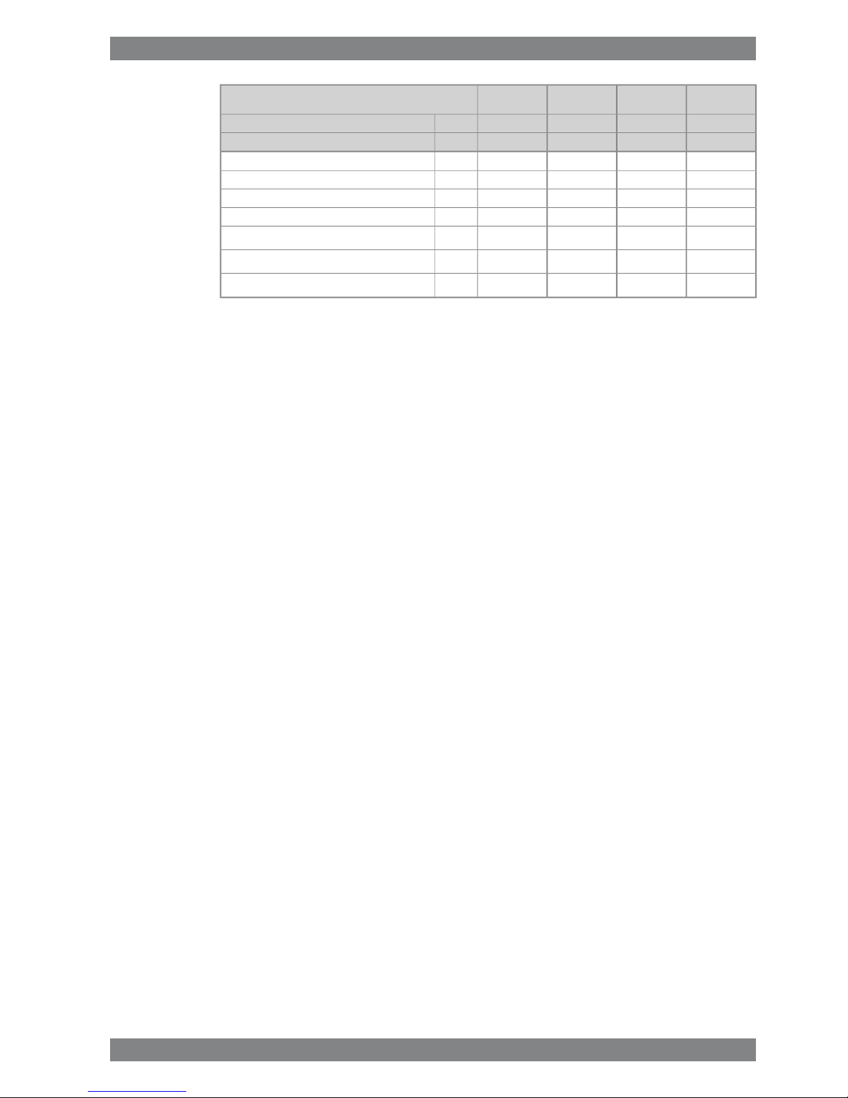
1.1 Maximum continuous output
Table 1-1 Rating table for Wärtsilä 26
Generating setsMain enginesCylinder configur-
ation
1000 rpm900 rpm1000 rpm900 rpm
[kWe][KVA][kWe][KVA][kW][kW]
1969246118822352204019506L26
2625328125093136272026008L26
2953369128233528306029259L26
39374922376447044080390012V26
52506562501862735440520016V26
The generator outputs are calculated for an efficiency of 96.5% and a power factor of 0.8.
The maximum fuel rack position is mechanically limited to 110% of the continuous output for
engines driving generators.
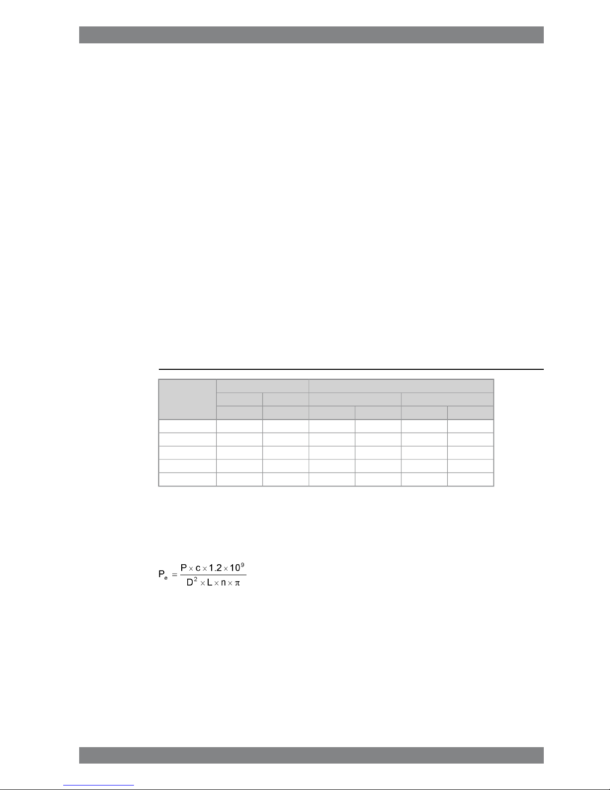
The mean effective pressure pecan be calculated as follows:
where:
mean effective pressure [bar]Pe=
output per cylinder [kW]P =
engine speed [rpm]n =
Cylinder diameter [mm]D =
length of piston stroke [mm]L =
operating cycle (4)c =
Wärtsilä 26 Product Guide - a9 - 7 September 2016 1-1
1. Main Data and OutputsWärtsilä 26 Product Guide

1.2 Reference conditions
The output is available up to a charge air coolant temperature of max. 38°C and an air
temperature of max. 45°C. For higher temperatures, the output has to be reduced according
to the formula stated in ISO 3046-1:2002 (E).
The specific fuel oil consumption is stated in the chapter Technical data. The stated specific
fuel oil consumption applies to engines with engine driven pumps, operating in ambient
conditions according to ISO 15550:2002 (E). The ISO standard reference conditions are:
100 kPatotal barometric pressure
25°Cair temperature
30%relative humidity
25°Ccharge air coolant temperature
Correction factors for the fuel oil consumption in other ambient conditions are given in standard
ISO 3046-1:2002.
1.3 Operation in inclined position
Max. inclination angles at which the engine will operate satisfactorily.
15.0°
● Transverse inclination, permanent (list)
22.5°
● Transverse inclination, momentary (roll)
5.0°
● Longitudinal inclination, permanent (trim)
7.5°
● Longitudinal inclination, momentary (pitch)
Larger angles are possible with special arrangements.
1-2 Wärtsilä 26 Product Guide - a9 - 7 September 2016
Wärtsilä 26 Product Guide1. Main Data and Outputs
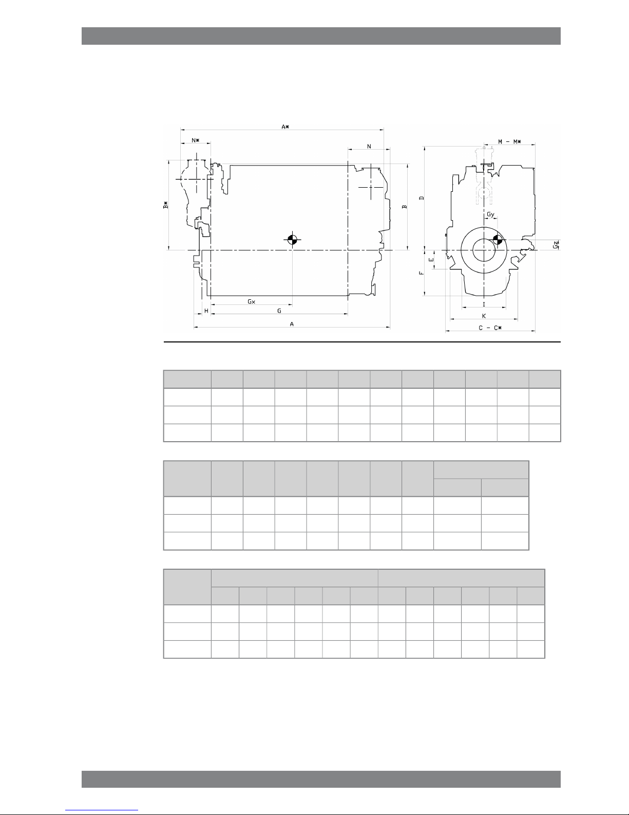
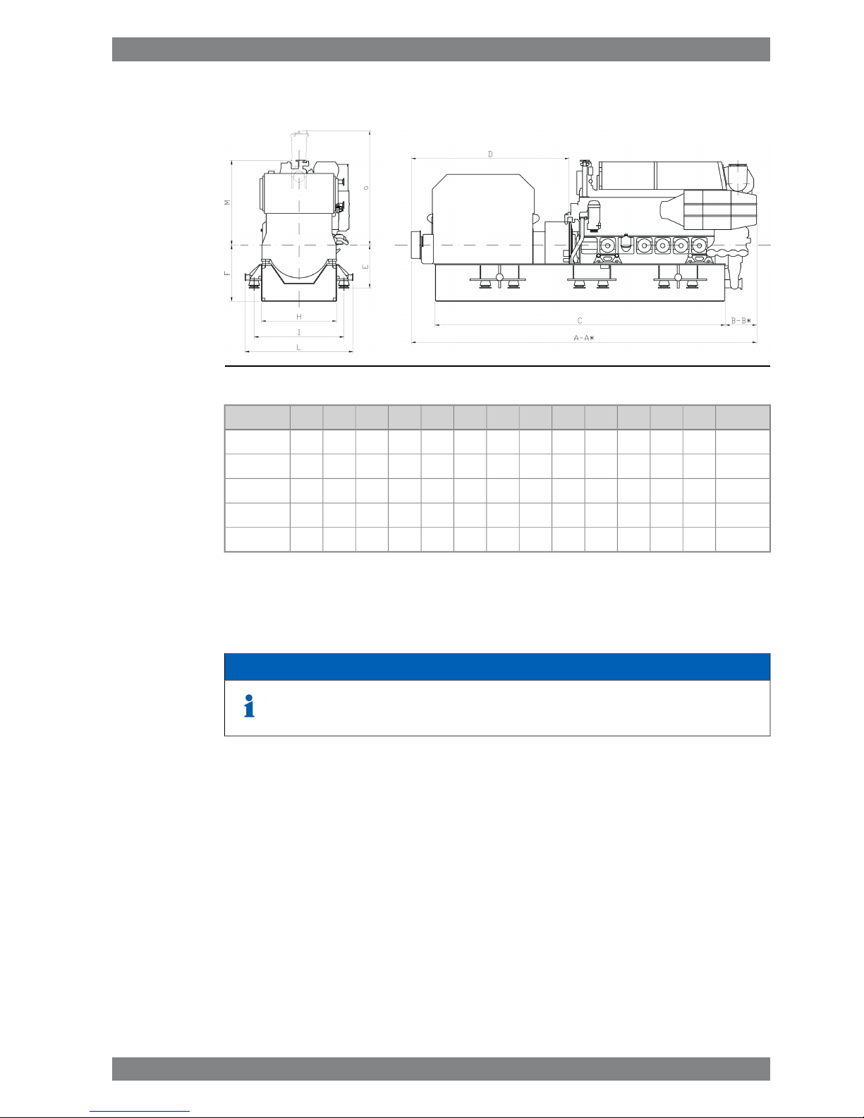
1.4 Dimensions and weights
1.4.1 Main engines
Fig 1-1 In-line engines (DAAE034755b)
GF
dry
F
wet
EDCC*BB*AA*Engine
28668189504002430202019601833188241304387W 6L26
36468189504002430210720101868202350595302W 8L26
40368189504002430210720161868202354495691W 9L26
Weight
NN*MM*KIHEngine
wet sumpdry sump
17.217.0904669117111031420920186W 6L26
21.921.61054794125811671420920186W 8L26
23.623.31054794125811671420920186W 9L26
Dry sumpWet sumpEngine
GzGyGxGz *Gy *Gx *GzGyGxGz *Gy *Gx *
458901300458901551450901300450901551W 6L26
465781704465782002457781704457782002W 8L26
462741921462742204454741921454742204W 9L26
* Turbocharger at flywheel end.
All dimensions in mm. Weight in metric tons with liquids (wet sump) but without flywheel.
Wärtsilä 26 Product Guide - a9 - 7 September 2016 1-3
1. Main Data and OutputsWärtsilä 26 Product Guide
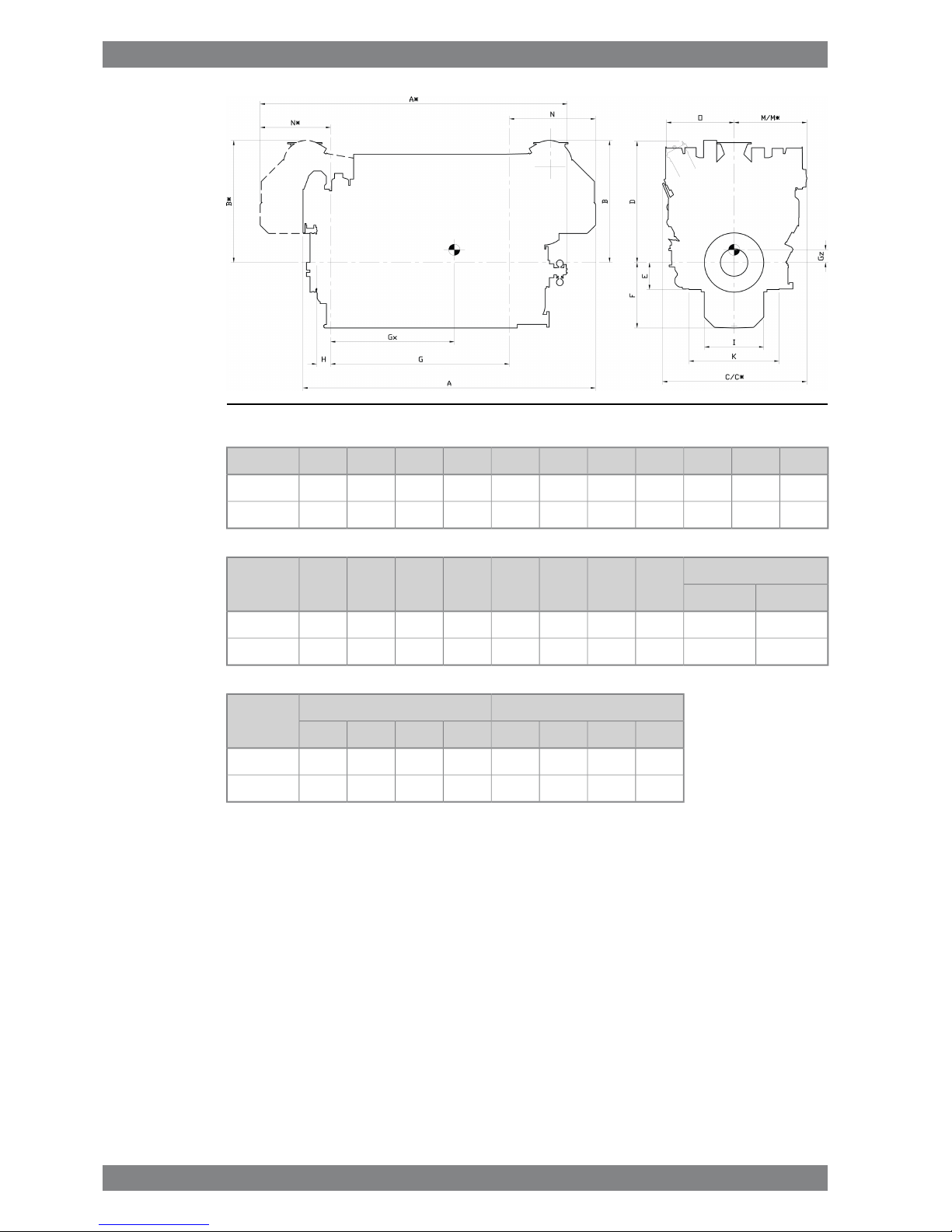
Fig 1-2 V-engines (DAAE034757b)
GF
dry
F
wet
EDCC*BB*AA*Engine
303580011104602060260225522034203453145442W 12V26
387580011104602060276324892190215160256223W 16V26
Weight
ONN *MM *KIHEngine
wet sumpdry sump
29.028.71148169814331238136415301010235W 12V26
37.936.11160162613631248124815301010235W 16V26
Dry sumpWet sumpEngine
GzGxGz *Gx *GzGxGz *Gx *
4701811470122441318114131224W 12V26
5682258568185254822585481852W 16V26
* Turbocharger at flywheel end.
All dimensions in mm. Weight in metric tons with liquids (wet sump) but without flywheel.
1-4 Wärtsilä 26 Product Guide - a9 - 7 September 2016
Wärtsilä 26 Product Guide1. Main Data and Outputs
1.4.2 Generating sets
Fig 1-3 Generating sets (DAAE034758b)
WeightMLIHGFEDCB*BA*AEngine
351833230019101600243012009213200600070283575007500W 6L26
451868230019101600243012009213300700070283580008000W 8L26
501868230019101600243013009213400750070283585008500W 9L26
602126**2700231020002765156098136006700-1263-8400W 12V26
702156**2700231020002765156098140007730-1400-9700W 16V26
* Turbocharger at flywheel end. ** TC inclination 30°
All dimensions in mm. Weight in metric tons with liquids (wet sump) but without flywheel.
NOTE
Generating set dimensions are for indication only, based on low voltage generators.
Final generating set dimensions and weights depend on selection of generator
and flexible coupling.
Wärtsilä 26 Product Guide - a9 - 7 September 2016 1-5
1. Main Data and OutputsWärtsilä 26 Product Guide

This page intentionally left blank
2. Operating Ranges
2.1 Engine operating range
Below nominal speed the load must be limited according to the diagrams in this chapter in
order to maintain engine operating parameters within acceptable limits. Operation in the
shaded area is permitted only temporarily during transients. Minimum speed is indicated in
the diagram, but project specific limitations may apply.
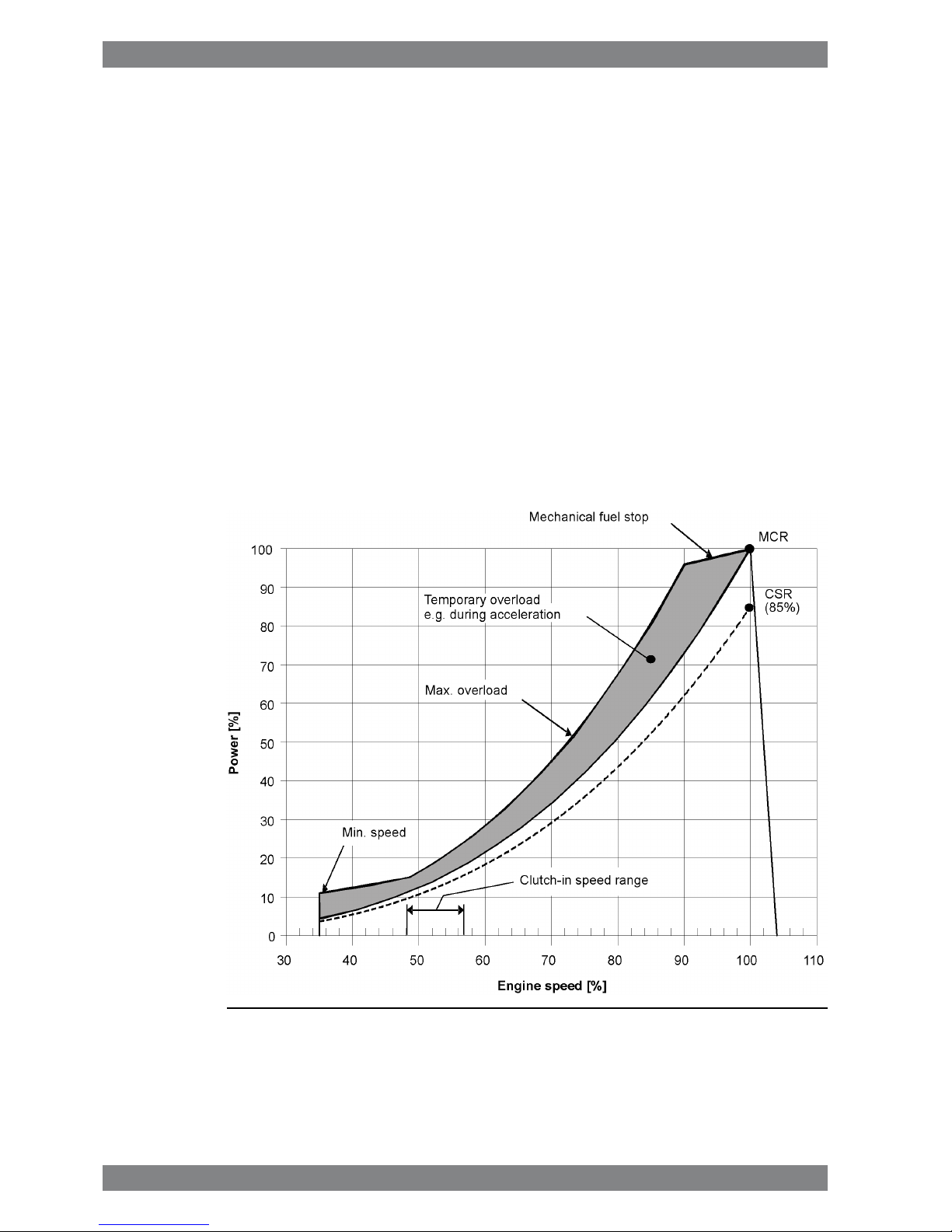
2.1.1 Controllable pitch propellers
An automatic load control system is required to protect the engine from overload. The load
control reduces the propeller pitch automatically, when a pre-programmed load versus speed
curve (“engine limit curve”) is exceeded, overriding the combinator curve if necessary. The
engine load is derived from fuel rack position and actual engine speed (not speed demand).
The propulsion control must also include automatic limitation of the load increase rate.
Maximum loading rates can be found later in this chapter.
The propeller efficiency is highest at design pitch. It is common practice to dimension the
propeller so that the specified ship speed is attained with design pitch, nominal engine speed
and 85% output in the specified loading condition. The power demand from a possible shaft
generator or PTO must be taken into account. The 15% margin is a provision for weather
conditions and fouling of hull and propeller. An additional engine margin can be applied for
most economical operation of the engine, or to have reserve power.
Fig 2-1 Operating field for CP propeller
Wärtsilä 26 Product Guide - a9 - 7 September 2016 2-1
2. Operating RangesWärtsilä 26 Product Guide
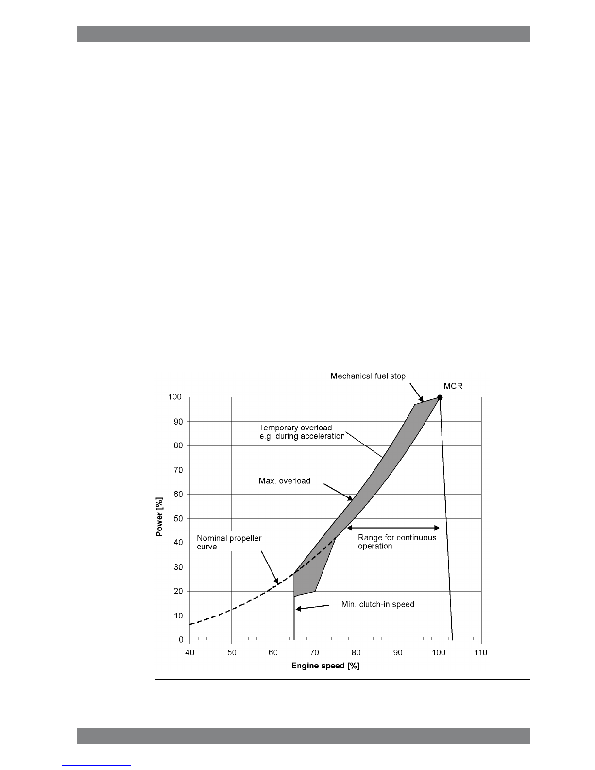
2.1.2 Fixed pitch propellers
The thrust and power absorption of a given fixed pitch propeller is determined by the relation
between ship speed and propeller revolution speed. The power absorption during acceleration,
manoeuvring or towing is considerably higher than during free sailing for the same revolution
speed. Increased ship resistance, for reason or another, reduces the ship speed, which
increases the power absorption of the propeller over the whole operating range.
Loading conditions, weather conditions, ice conditions, fouling of hull, shallow water, and
manoeuvring requirements must be carefully considered, when matching a fixed pitch propeller
to the engine. The nominal propeller curve shown in the diagram must not be exceeded in
service, except temporarily during acceleration and manoeuvring. A fixed pitch propeller for
a free sailing ship is therefore dimensioned so that it absorbs max. 85% of the engine output
at nominal engine speed during trial with loaded ship. Typically this corresponds to about
82% for the propeller itself.
If the vessel is intended for towing, the propeller is dimensioned to absorb 95% of the engine
power at nominal engine speed in bollard pull or towing condition. It is allowed to increase
the engine speed to 101.7% in order to reach 100% MCR during bollard pull.
A shaft brake should be used to enable faster reversing and shorter stopping distance (crash
stop). The ship speed at which the propeller can be engaged in reverse direction is still limited
by the windmilling torque of the propeller and the torque capability of the engine at low
revolution speed.
Fig 2-2 Operating field for FP Propeller
2.1.2.1 FP propellers in twin screw vessels
Requirements regarding manoeuvring response and acceleration, as well as overload with
one engine out of operation must be very carefully evaluated if the vessel is designed for free
2-2 Wärtsilä 26 Product Guide - a9 - 7 September 2016
Wärtsilä 26 Product Guide2. Operating Ranges
sailing, in particular if open propellers are applied. If the bollard pull curve significantly exceeds
the maximum overload limit, acceleration and manoeuvring response can be very slow. Nozzle
propellers are less problematic in this respect.
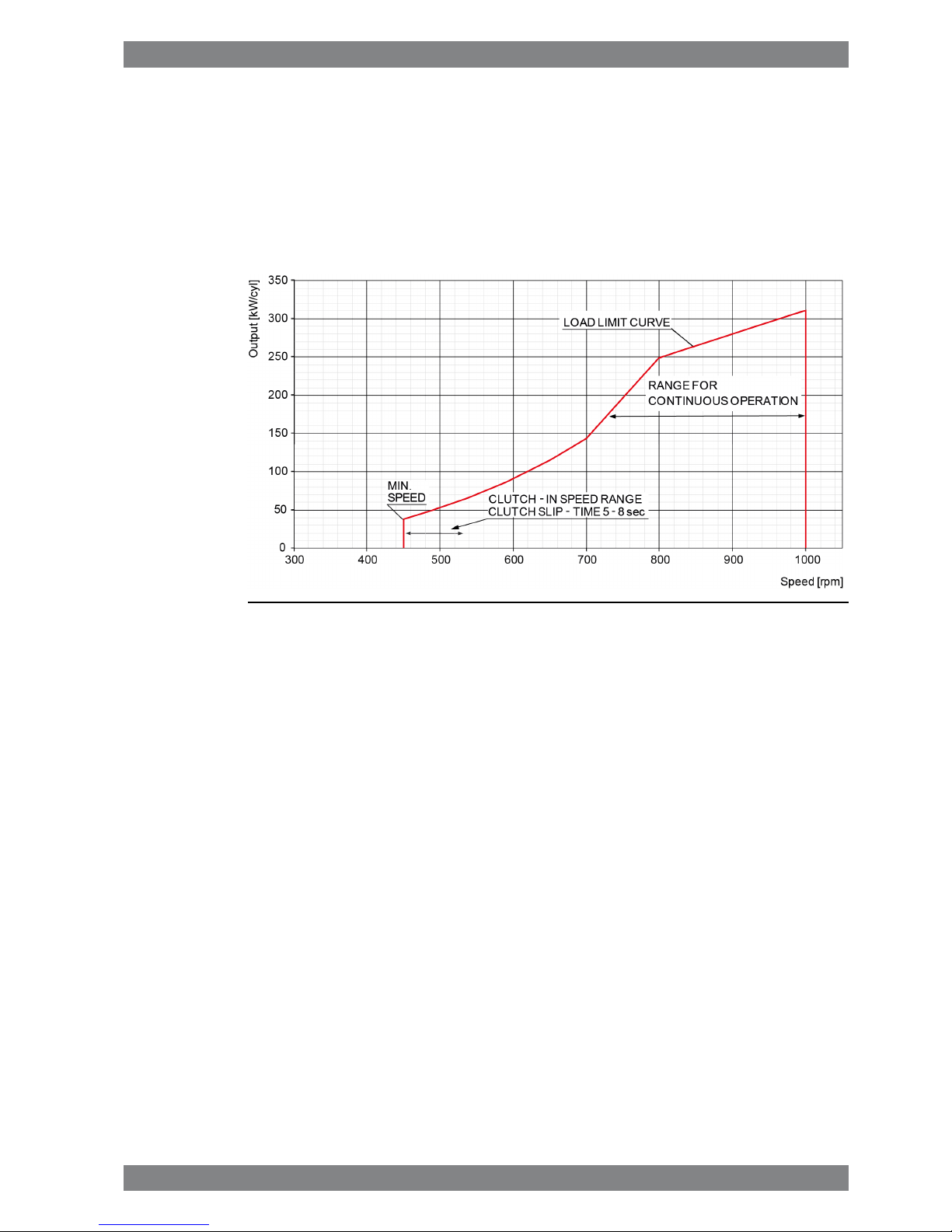
2.1.3 Dredgers
Mechanically driven dredging pumps typically require a capability to operate with full torque
down to 80% of nominal engine speed. This requirement results in significant de-rating of the
engine.
Fig 2-3 Operating field for Dredgers
2.2 Loading capacity
Controlled load increase is essential for highly supercharged diesel engines, because the
turbocharger needs time to accelerate before it can deliver the required amount of air. A slower
loading ramp than the maximum capability of the engine permits a more even temperature
distribution in engine components during transients.
The engine can be loaded immediately after start, provided that the engine is pre-heated to
a HT-water temperature of 60…70ºC, and the lubricating oil temperature is min. 40 ºC.
The ramp for normal loading applies to engines that have reached normal operating
temperature.
Wärtsilä 26 Product Guide - a9 - 7 September 2016 2-3
2. Operating RangesWärtsilä 26 Product Guide
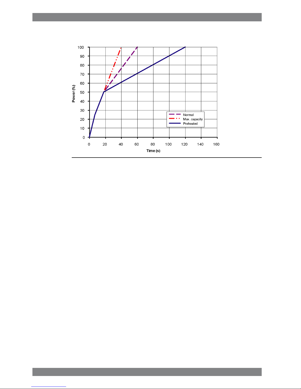
2.2.1 Mechanical propulsion
Fig 2-4 Maximum recommended load increase rates for variable speed engines
The propulsion control must include automatic limitation of the load increase rate. If the control
system has only one load increase ramp, then the ramp for a preheated engine should be
used. In tug applications the engines have usually reached normal operating temperature
before the tug starts assisting. The “emergency” curve is close to the maximum capability of
the engine.
If minimum smoke during load increase is a major priority, slower loading rate than in the
diagram can be necessary below 50% load.
Large load reductions from high load should also be performed gradually. In normal operation
the load should not be reduced from 100% to 0% in less than 15 seconds. When absolutely
necessary, the load can be reduced as fast as the pitch setting system can react (overspeed
due to windmilling must be considered for high speed ships).
2-4 Wärtsilä 26 Product Guide - a9 - 7 September 2016
Wärtsilä 26 Product Guide2. Operating Ranges
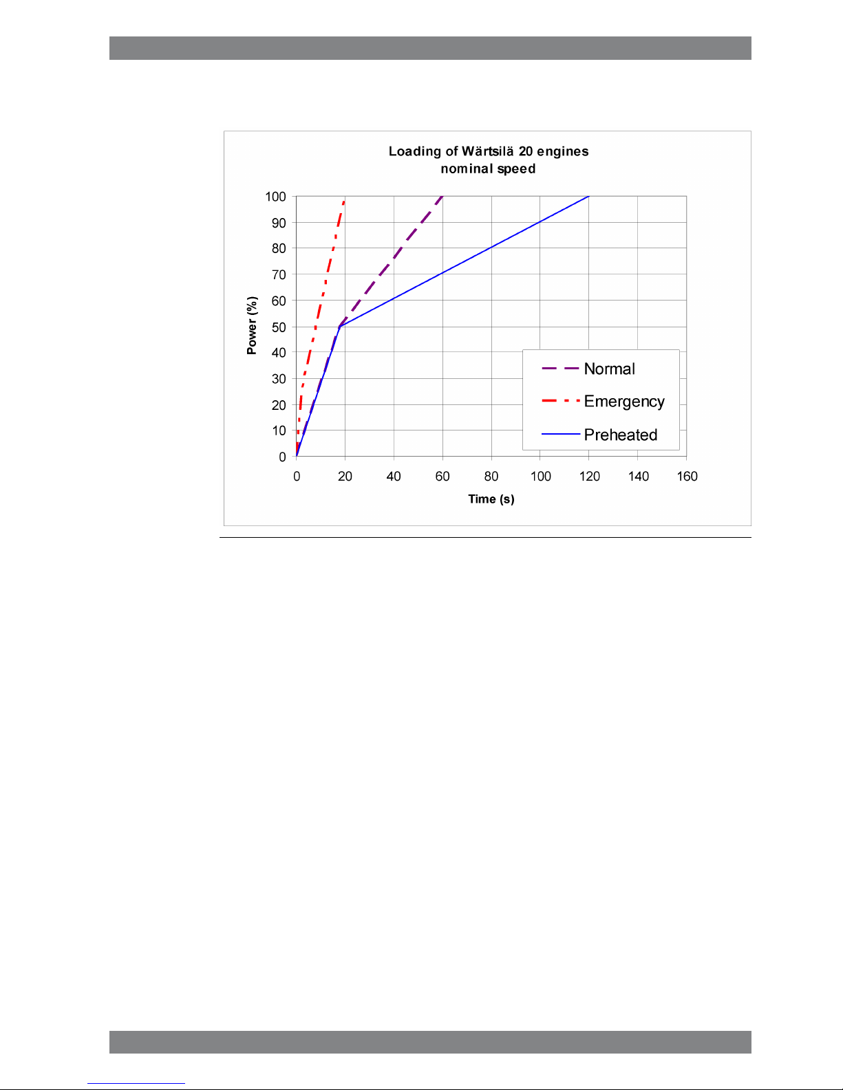
2.2.2 Diesel electric propulsion and auxiliary engines
Fig 2-5 Maximum recommended load increase rates for engines operating at
nominal speed
In diesel electric installations loading ramps are implemented both in the propulsion control
and in the power management system, or in the engine speed control in case isochronous
load sharing is applied. If a ramp without knee-point is used, it should not achieve 100% load
in shorter time than the ramp in the figure. When the load sharing is based on speed droop,
the load increase rate of a recently connected generator is the sum of the load transfer
performed by the power management system and the load increase performed by the
propulsion control.
The “emergency” curve is close to the maximum capability of the engine and it shall not be
used as the normal limit. In dynamic positioning applications loading ramps corresponding to
20-30 seconds from zero to full load are however normal. If the vessel has also other operating
modes, a slower loading ramp is recommended for these operating modes.
In typical auxiliary engine applications there is usually no single consumer being decisive for
the loading rate. It is recommended to group electrical equipment so that the load is increased
in small increments, and the resulting loading rate roughly corresponds to the “normal” curve.
In normal operation the load should not be reduced from 100% to 0% in less than 15 seconds.
If the application requires frequent unloading at a significantly faster rate, special arrangements
can be necessary on the engine. In an emergency situation the full load can be thrown off
instantly.
2.2.2.1 Maximum instant load steps
The electrical system must be designed so that tripping of breakers can be safely handled.
This requires that the engines are protected from load steps exceeding their maximum load
acceptance capability. The maximum permissible load step is 30% MCR. The resulting speed
Wärtsilä 26 Product Guide - a9 - 7 September 2016 2-5
2. Operating RangesWärtsilä 26 Product Guide

drop is less than 10% and the recovery time to within 1% of the steady state speed at the
new load level is max. 5 seconds.
When electrical power is restored after a black-out, consumers are reconnected in groups,
which may cause significant load steps. The engine can be loaded in three steps up to 100%
load, provided that the steps are 0-30-65-100. The engine must be allowed to recover for at
least 7 seconds before applying the following load step, if the load is applied in maximum
steps.
2.2.2.2 Start-up time
A diesel generator typically reaches nominal speed in about 20...25 seconds after the start
signal. The acceleration is limited by the speed control to minimise smoke during start-up.
2.3 Operation at low load and idling
The engine can be started, stopped and operated on heavy fuel under all operating conditions.
Continuous operation on heavy fuel is preferred rather than changing over to diesel fuel at low
load operation and manoeuvring. The following recommendations apply:
Absolute idling (declutched main engine, disconnected generator)
● Maximum 10 minutes if the engine is to be stopped after the idling. 3-5 minutes idling
before stop is recommended.
● Maximum 6 hours if the engine is to be loaded after the idling.
Operation below 20 % load
● Maximum 100 hours continuous operation. At intervals of 100 operating hours the engine
must be loaded to minimum 70 % of the rated output.
Operation above 20 % load
● No restrictions.
NOTE
For operation profiles involving prolonged low load operation, please contact
Wärtsilä.
2.4 Low air temperature
In cold conditions the following minimum inlet air temperatures apply:
● Starting + 5ºC
● Idling - 5ºC
● High load - 10ºC
If the engine is equipped with a two-stage charge air cooler, sustained operation between 0
and 40% load can require special provisions in cold conditions to prevent too low engine
temperature.
For further guidelines, see chapter Combustion air system design.
2-6 Wärtsilä 26 Product Guide - a9 - 7 September 2016
Wärtsilä 26 Product Guide2. Operating Ranges
3. Technical Data
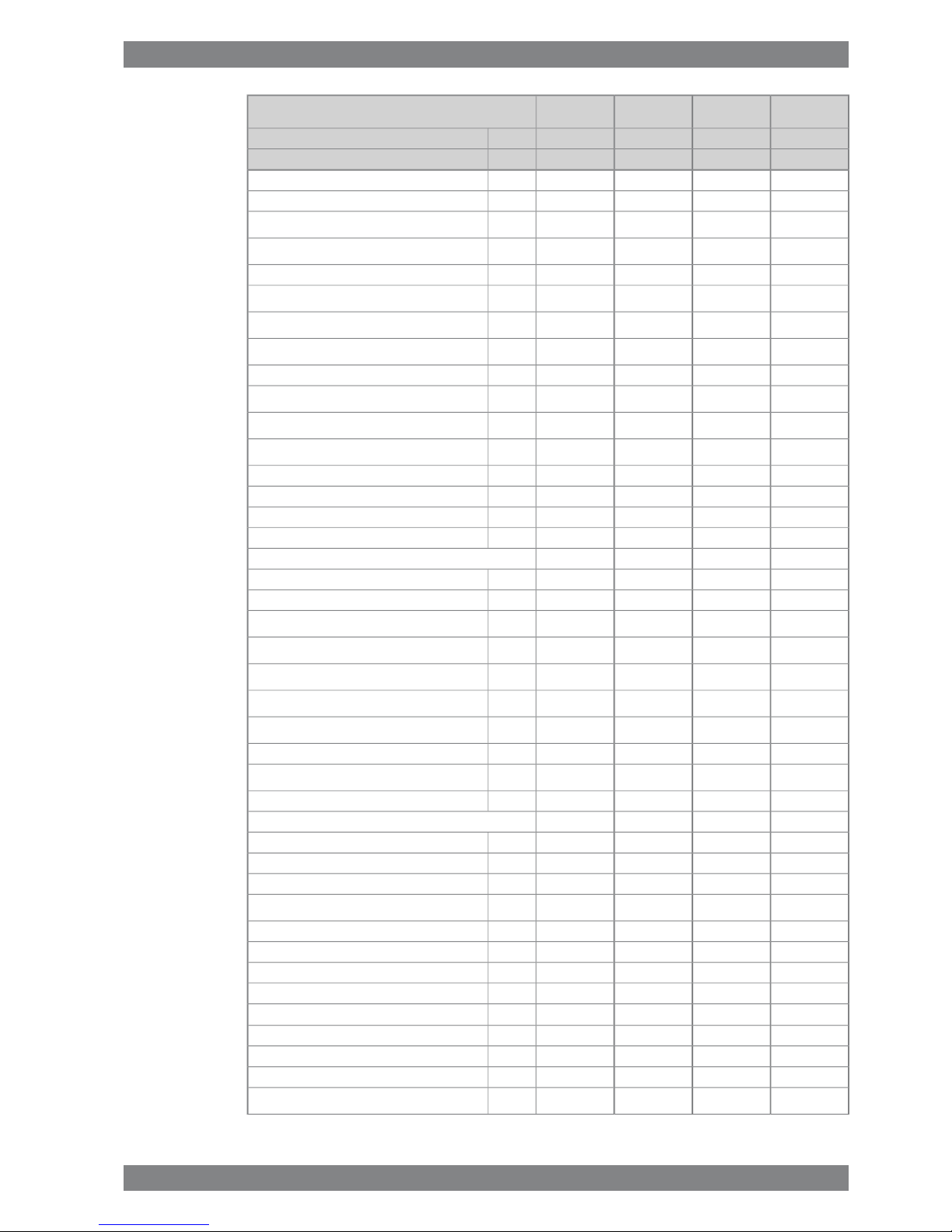
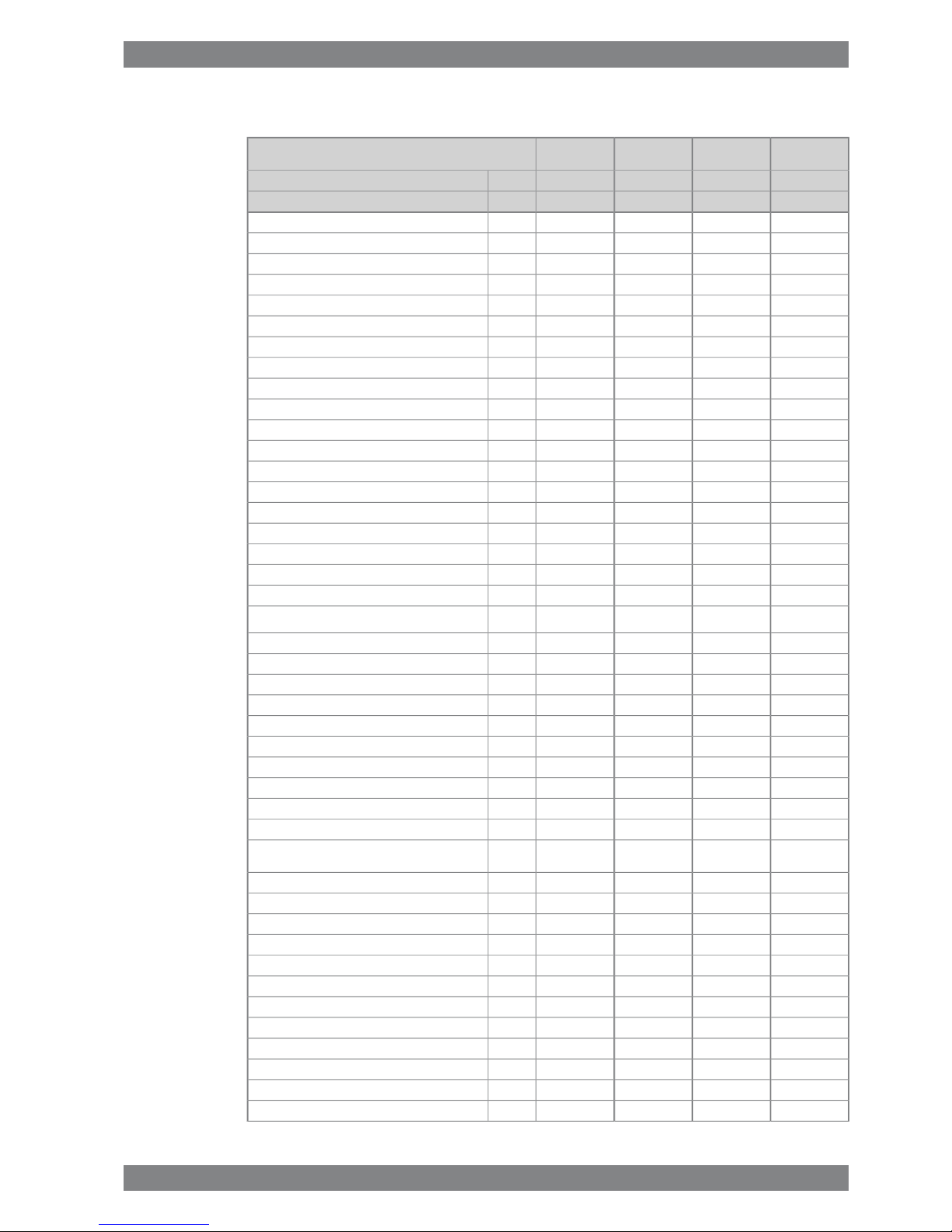
3.1 Wärtsilä 6L26
Table 3-1
ME
IMO Tier 1
ME
IMO Tier 1
AE/DE
IMO Tier 1
AE/DE
IMO Tier 1
Wärtsilä 6L26
340325340325kW/cylCylinder output
10009001000900rpmEngine speed
2040195020401950kWEngine output
2.42.552.42.55MPaMean effective pressure
Combustion air system (Note 1)
4.13.94.13.7kg/sFlow of air at 100% load
45454545°CTemperature at turbocharger intake, max.
55555555°CAir temperature after air cooler, nom. (TE601)
Exhaust gas system (Note 2)
4.24.24.13.8kg/sFlow at 100% load
3.63.63.73.3kg/sFlow at 85% load
3.03.03.43.0kg/sFlow 75% load
2.41.82.92.6kg/sFlow 50% load
312306312329°CTemp. after turbo, 100% load (TE517)
313311304326°CTemp. after turbo, 85% load (TE517)
327326311337°CTemp. after turbo, 75% load (TE517)
322327252271°CTemp. after turbo, 50% load (TE517)
3.03.03.03.0kPaBackpressure, max.
500500500500mmExhaust gas pipe diameter, min
502499498487
mmCalculated exhaust diameter for 35 m/s
Heat balance (Note 3)
354318354330kWJacket water
300276300282kWLubricating oil
750720750636kWCharge air
96909690kWRadiation
Fuel system (Note 4)
700±50700±50700±50700±50kPaPressure before injection pumps (PT101)
3.22.93.22.9m³/hEngine driven pump capacity at 12 cSt (MDF only)
1.71.61.71.6m3/hFuel flow to engine (without engine driven pump),
approx.
16...2416...2416...2416...24cStHFO viscosity before engine
140140140140°CHFO temperature before engine, max. (TE 101)
2.02.02.02.0cStMDF viscosity, min
45454545°CMDF temperature before engine, max. (TE 101)
192190192189g/kWhFuel consumption at 100% load
190187191187g/kWhFuel consumption at 85% load
Wärtsilä 26 Product Guide - a9 - 7 September 2016 3-1
3. Technical DataWärtsilä 26 Product Guide
ME
IMO Tier 1
ME
IMO Tier 1
AE/DE
IMO Tier 1
AE/DE
IMO Tier 1
Wärtsilä 6L26
340325340325kW/cylCylinder output
10009001000900rpmEngine speed
193190194191g/kWhFuel consumption at 75% load
196191202198g/kWhFuel consumption at 50% load
8.27.88.27.7kg/hClean leak fuel quantity, MDF at 100% load
1.61.61.61.5kg/hClean leak fuel quantity, HFO at 100% load
Lubricating oil system (Note 5)
450450450450kPaPressure before bearings, nom. (PT201)
800800800800kPaPressure after pump, max.
30303030
kPaSuction ability including pipe loss, max.
80808080
kPaPriming pressure, nom. (PT201)
68686868°CTemperature before bearings, nom. (TE201)
78787878
°CTemperature after engine, approx.
66606660
m³/hPump capacity (main), engine driven
55555555
m³/hPump capacity (main), stand-by
11 / 1311 / 1311 / 1311 / 13m³/hPriming pump capacity, 50Hz/60Hz
1.31.31.31.3
m³Oil volume, wet sump, nom.
2.82.62.82.6
m³Oil volume in separate system oil tank, nom.
0.50.50.50.5
g/kWhOil consumption (100% load), approx.
150150150150l/min/cylCrankcase ventilation flow rate
0.30.30.30.3kPaCrankcase backpressure (max)
1.4 / 2.01.4 / 2.01.4 / 2.01.4 / 2.0lOil volume in speed governor
High temperature cooling water system
350 + static350 + static350 + static350 + statickPaPressure at engine, after pump, nom. (PT401)
500500500500kPaPressure at engine, after pump, max. (PT401)
81818181
°CTemperature before cylinders, approx. (TE401)
91919191
°CHT-water out from the engine, nom (TE402)
35353535
m³/hCapacity of engine driven pump, nom.
210210210210
kPaPressure drop over engine
60606060
kPaPressure drop in external system, max
70...15070...15070...15070...150kPaPressure from expansion tank
0.30.30.30.3
m³Water volume in engine
Low temperature cooling water system
280 + static260 + static280 + static260 + statickPaPressure at engine, after pump, nom. (PT471)
500500500500kPaPressure at engine, after pump, max. (PT471)
25...3825...3825...3825...38°CTemperature before engine (TE471)
47424742
m³/hCapacity of engine driven pump, nom.
60606060kPaPressure drop in external system, max.
50505050kPaPressure drop over charge air cooler
16161616kPaPressure drop over oil cooler
70...15070...15070...15070...150kPaPressure from expansion tank
3-2 Wärtsilä 26 Product Guide - a9 - 7 September 2016
Wärtsilä 26 Product Guide3. Technical Data
ME
IMO Tier 1
ME
IMO Tier 1
AE/DE
IMO Tier 1
AE/DE
IMO Tier 1
Wärtsilä 6L26
340325340325kW/cylCylinder output
10009001000900rpmEngine speed
80808080m3/hCapacity engine driven seawater pump, max.
Starting air system (Note 6)
3000300030003000kPaPressure, nom.
3300330033003300
kPaPressure, max.
1800180018001800
kPaLow pressure limit in air vessels
1.41.41.41.4
Nm
3
Starting air consumption, start (successful)
Notes:
At ISO 15550 conditions (ambient air temperature 25°C, LT-water 25°C) and 100% load. Flow tolerance 5%.Note 1
At ISO 15550 conditions (ambient air temperature 25°C, LT-water 25°C). Flow tolerance 5% and temperature tolerance
20°C.
Note 2
The heat balances are made for ISO 15550standard reference conditions. The heat balances include engine driven pumps
(two water pumps and one lube oil pump).
Note 3
According to ISO 15550, lower calorific value 42700 kJ/kg at constant engine speed, with engine driven pumps (two
cooling water + one lubricating oil pumps). Tolerance 5%.The fuel consumptionat85 % load is guaranteed and the values
at other loads are given for indication only.
Note 4
Speed governor oil volume depends on the speed governor type.Note 5
At manual starting the consumption may be 2...3 times lower.Note 6
ME = Engine driving propeller, variable speed
AE = Auxiliary engine driving generator
DE = Diesel-Electric engine driving generator
Subject to revision without notice.
Wärtsilä 26 Product Guide - a9 - 7 September 2016 3-3
3. Technical DataWärtsilä 26 Product Guide

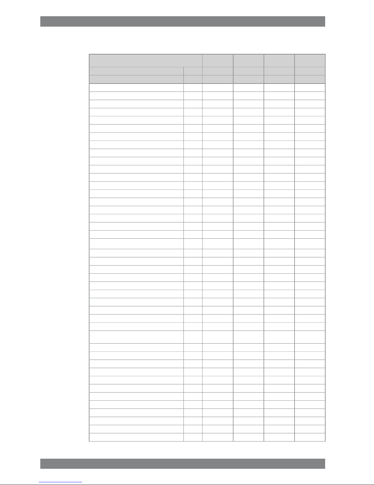
3.2 Wärtsilä 8L26
ME
IMO Tier 1
ME
IMO Tier 1
AE/DE
IMO Tier 1
AE/DE
IMO Tier 1
Wärtsilä 8L26
340325340325kW/cylCylinder output
10009001000900rpmEngine speed
2720260027202600kWEngine output
2.42.552.42.55MPaMean effective pressure
Combustion air system (Note 1)
5.45.25.45.0kg/sFlow of air at 100% load
45454545°CTemperature at turbocharger intake, max.
55555555°CAir temperature after air cooler, nom. (TE601)
Exhaust gas system (Note 2)
5.65.65.55.1kg/sFlow at 100% load
4.84.84.94.4kg/sFlow at 85% load
4.04.04.54.0kg/sFlow 75% load
3.22.43.93.4kg/sFlow 50% load
312306312329°CTemp. after turbo, 100% load (TE517)
313311304326°CTemp. after turbo, 85% load (TE517)
327326311337°CTemp. after turbo, 75% load (TE517)
322327252342°CTemp. after turbo, 50% load (TE517)
3.03.03.03.0kPaBackpressure, max.
550550550550mmExhaust gas pipe diameter, min
579577575562
mmCalculated exhaust diameter for 35 m/s
Heat balance (Note 3)
472424472440kWJacket water
400368400376kWLubricating oil
10009601000848kWCharge air
128120128120kWRadiation
Fuel system (Note 4)
700±50700±50700±50700±50kPaPressure before injection pumps (PT101)
4.13.72.92.9m³/hEngine driven pump capacity at 12 cSt (MDF only)
2.32.22.32.2m3/hFuel flow to engine (without engine driven pump),
approx.
16...2416...2416...2416...24cStHFO viscosity before engine
140140140140°CHFO temperature before engine, max. (TE 101)
2.02.02.02.0cStMDF viscosity, min
45454545°CMDF temperature before engine, max. (TE 101)
192190192189g/kWhFuel consumption at 100% load
190187191187g/kWhFuel consumption at 85% load
193190194191g/kWhFuel consumption at 75% load
196191202198g/kWhFuel consumption at 50% load
10.910.310.910.3kg/hClean leak fuel quantity, MDF at 100% load
2.22.12.22.1kg/hClean leak fuel quantity, HFO at 100% load
Lubricating oil system (Note 5)
3-4 Wärtsilä 26 Product Guide - a9 - 7 September 2016
Wärtsilä 26 Product Guide3. Technical Data
ME
IMO Tier 1
ME
IMO Tier 1
AE/DE
IMO Tier 1
AE/DE
IMO Tier 1
Wärtsilä 8L26
340325340325kW/cylCylinder output
10009001000900rpmEngine speed
450450450450kPaPressure before bearings, nom. (PT201)
800800800800kPaPressure after pump, max.
30303030
kPaSuction ability including pipe loss, max.
80808080
kPaPriming pressure, nom. (PT201)
68686868°CTemperature before bearings, nom. (TE201)
78787878
°CTemperature after engine, approx.
90819081
m³/hPump capacity (main), engine driven
75757575
m³/hPump capacity (main), stand-by
16 / 1916 / 1916 / 1916 / 19m³/hPriming pump capacity, 50Hz/60Hz
1.61.61.61.6
m³Oil volume, wet sump, nom.
3.73.53.73.5
m³Oil volume in separate system oil tank, nom.
0.50.50.50.5
g/kWhOil consumption (100% load), approx.
150150150150l/min/cylCrankcase ventilation flow rate
0.30.30.30.3kPaCrankcase backpressure (max)
1.4 / 2.01.4 / 2.01.4 / 2.01.4 / 2.0lOil volume in speed governor
High temperature cooling water system
370 + static360 + static370 + static360 + statickPaPressure at engine, after pump, nom. (PT401)
500500500500kPaPressure at engine, after pump, max. (PT401)
81818181
°CTemperature before cylinders, approx. (TE401)
91919191
°CHT-water out from the engine, nom (TE402)
45454545
m³/hCapacity of engine driven pump, nom.
220220220220
kPaPressure drop over engine
60606060
kPaPressure drop in external system, max
70...15070...15070...15070...150kPaPressure from expansion tank
0.40.40.40.4
m³Water volume in engine
Low temperature cooling water system
250 + static270 + static250 + static270 + statickPaPressure at engine, after pump, nom. (PT471)
500500500500kPaPressure at engine, after pump, max. (PT471)
25...3825...3825...3825...38°CTemperature before engine (TE471)
62566256
m³/hCapacity of engine driven pump, nom.
60606060kPaPressure drop in external system, max.
50505050kPaPressure drop over charge air cooler
18181818kPaPressure drop over oil cooler
70...15070...15070...15070...150kPaPressure from expansion tank
120120120120m3/hCapacity engine driven seawater pump, max.
Starting air system (Note 6)
3000300030003000kPaPressure, nom.
3300330033003300
kPaPressure, max.
Wärtsilä 26 Product Guide - a9 - 7 September 2016 3-5
3. Technical DataWärtsilä 26 Product Guide

ME
IMO Tier 1
ME
IMO Tier 1
AE/DE
IMO Tier 1
AE/DE
IMO Tier 1
Wärtsilä 8L26
340325340325kW/cylCylinder output
10009001000900rpmEngine speed
1800180018001800
kPaLow pressure limit in air vessels
1.81.81.81.8
Nm
3
Starting air consumption, start (successful)
Notes:
At ISO 15550 conditions (ambient air temperature 25°C, LT-water 25°C) and 100% load. Flow tolerance 5%.Note 1
At ISO 15550 conditions (ambient air temperature 25°C, LT-water 25°C). Flow tolerance 5% and temperature tolerance
20°C.
Note 2
The heat balances are made for ISO 15550standard reference conditions. The heat balances include engine driven pumps
(two water pumps and one lube oil pump).
Note 3
According to ISO 15550, lower calorific value 42700 kJ/kg at constant engine speed, with engine driven pumps (two
cooling water + one lubricating oil pumps). Tolerance 5%.The fuel consumptionat85 % load is guaranteed and the values
at other loads are given for indication only.
Note 4
Speed governor oil volume depends on the speed governor type.Note 5
At manual starting the consumption may be 2...3 times lower.Note 6
ME = Engine driving propeller, variable speed
AE = Auxiliary engine driving generator
DE = Diesel-Electric engine driving generator
Subject to revision without notice.
3-6 Wärtsilä 26 Product Guide - a9 - 7 September 2016
Wärtsilä 26 Product Guide3. Technical Data
3.3 Wärtsilä 9L26
ME
IMO Tier 1
ME
IMO Tier 1
AE/DE
IMO Tier 1
AE/DE
IMO Tier 1
Wärtsilä 9L26
340325340325kW/cylCylinder output
10009001000900rpmEngine speed
3060292530602925kWEngine output
2.42.552.42.55MPaMean effective pressure
Combustion air system (Note 1)
6.05.86.15.6kg/sFlow of air at 100% load
45454545°CTemperature at turbocharger intake, max.
55555555°CAir temperature after air cooler, nom. (TE601)
Exhaust gas system (Note 2)
6.36.36.25.8kg/sFlow at 100% load
5.45.45.55.0kg/sFlow at 85% load
4.54.55.04.5kg/sFlow 75% load
3.62.74.43.9kg/sFlow 50% load
312306312329°CTemp. after turbo, 100% load (TE517)
313311304326°CTemp. after turbo, 85% load (TE517)
327326311337°CTemp. after turbo, 75% load (TE517)
322327252342°CTemp. after turbo, 50% load (TE517)
3.03.03.03.0kPaBackpressure, max.
600600600600mmExhaust gas pipe diameter, min
615611610596
mmCalculated exhaust diameter for 35 m/s
Heat balance (Note 3)
531477531495kWJacket water
450414450423kWLubricating oil
112510801125954kWCharge air
144135144135kWRadiation
Fuel system (Note 4)
700±50700±50700±50700±50kPaPressure before injection pumps (PT101)
4.13.74.13.7m³/hEngine driven pump capacity at 12 cSt (MDF only)
2.62.42.62.4m3/hFuel flow to engine (without engine driven pump),
approx.
16...2416...2416...2416...24cStHFO viscosity before engine
140140140140°CHFO temperature before engine, max. (TE 101)
2.02.02.02.0cStMDF viscosity, min
45454545°CMDF temperature before engine, max. (TE 101)
192190192189g/kWhFuel consumption at 100% load
190187191187g/kWhFuel consumption at 85% load
193190194191g/kWhFuel consumption at 75% load
196191202198g/kWhFuel consumption at 50% load
12.311.612.311.6kg/hClean leak fuel quantity, MDF at 100% load
2.52.32.52.3kg/hClean leak fuel quantity, HFO at 100% load
Lubricating oil system (Note 5)
Wärtsilä 26 Product Guide - a9 - 7 September 2016 3-7
3. Technical DataWärtsilä 26 Product Guide

ME
IMO Tier 1
ME
IMO Tier 1
AE/DE
IMO Tier 1
AE/DE
IMO Tier 1
Wärtsilä 9L26
340325340325kW/cylCylinder output
10009001000900rpmEngine speed
450450450450kPaPressure before bearings, nom. (PT201)
800800800800kPaPressure after pump, max.
30303030
kPaSuction ability including pipe loss, max.
80808080
kPaPriming pressure, nom. (PT201)
68686868°CTemperature before bearings, nom. (TE201)
78787878
°CTemperature after engine, approx.
90819081
m³/hPump capacity (main), engine driven
75757575
m³/hPump capacity (main), stand-by
16 / 1916 / 1916 / 1916 / 19m³/hPriming pump capacity, 50Hz/60Hz
1.71.71.71.7
m³Oil volume, wet sump, nom.
4.13.94.13.9
m³Oil volume in separate system oil tank, nom.
0.50.50.50.5
g/kWhOil consumption (100% load), approx.
150150150150l/min/cylCrankcase ventilation flow rate
0.30.30.30.3kPaCrankcase backpressure (max)
1.4 / 2.01.4 / 2.01.4 / 2.01.4 / 2.0lOil volume in speed governor
High temperature cooling water system
350 + static360 + static350 + static360 + statickPaPressure at engine, after pump, nom. (PT401)
500500500500kPaPressure at engine, after pump, max. (PT401)
81818181
°CTemperature before cylinders, approx. (TE401)
91919191
°CHT-water out from the engine, nom (TE402)
50505050
m³/hCapacity of engine driven pump, nom.
220220220220
kPaPressure drop over engine
60606060
kPaPressure drop in external system, max
70...15070...15070...15070...150kPaPressure from expansion tank
0.450.450.450.45
m³Water volume in engine
Low temperature cooling water system
260 + static250 + static260 + static250 + statickPaPressure at engine, after pump, nom. (PT471)
500500500500kPaPressure at engine, after pump, max. (PT471)
25...3825...3825...3825...38°CTemperature before engine (TE471)
70637063
m³/hCapacity of engine driven pump, nom.
60606060kPaPressure drop in external system, max.
50505050kPaPressure drop over charge air cooler
21212121kPaPressure drop over oil cooler
70...15070...15070...15070...150kPaPressure from expansion tank
120120120120m3/hCapacity engine driven seawater pump, max.
Starting air system (Note 6)
3000300030003000kPaPressure, nom.
3300330033003300
kPaPressure, max.
3-8 Wärtsilä 26 Product Guide - a9 - 7 September 2016
Wärtsilä 26 Product Guide3. Technical Data

ME
IMO Tier 1
ME
IMO Tier 1
AE/DE
IMO Tier 1
AE/DE
IMO Tier 1
Wärtsilä 9L26
340325340325kW/cylCylinder output
10009001000900rpmEngine speed
1800180018001800
kPaLow pressure limit in air vessels
2.02.02.02.0
Nm
3
Starting air consumption, start (successful)
Notes:
At ISO 15550 conditions (ambient air temperature 25°C, LT-water 25°C) and 100% load. Flow tolerance 5%.Note 1
At ISO 15550 conditions (ambient air temperature 25°C, LT-water 25°C). Flow tolerance 5% and temperature tolerance
20°C.
Note 2
The heat balances are made for ISO 15550standard reference conditions. The heat balances include engine driven pumps
(two water pumps and one lube oil pump).
Note 3
According to ISO 15550, lower calorific value 42700 kJ/kg at constant engine speed, with engine driven pumps (two
cooling water + one lubricating oil pumps). Tolerance 5%.The fuel consumptionat85 % load is guaranteed and the values
at other loads are given for indication only.
Note 4
Speed governor oil volume depends on the speed governor type.Note 5
At manual starting the consumption may be 2...3 times lower.Note 6
ME = Engine driving propeller, variable speed
AE = Auxiliary engine driving generator
DE = Diesel-Electric engine driving generator
Subject to revision without notice.
Wärtsilä 26 Product Guide - a9 - 7 September 2016 3-9
3. Technical DataWärtsilä 26 Product Guide
3.4 Wärtsilä 12V26
ME
IMO Tier 1
ME
IMO Tier 1
AE/DE
IMO Tier 1
AE/DE
IMO Tier 1
Wärtsilä 12V26
340325340325kW/cylCylinder output
10009001000900rpmEngine speed
4080390040803900kWEngine output
2.42.552.42.55MPaMean effective pressure
Combustion air system (Note 1)
8.28.08.17.5kg/sFlow of air at 100% load
45454545°CTemperature at turbocharger intake, max.
50505050°CAir temperature after air cooler, nom. (TE601)
Exhaust gas system (Note 2)
8.48.48.37.7kg/sFlow at 100% load
7.27.27.36.6kg/sFlow at 85% load
6.06.06.76.0kg/sFlow 75% load
4.83.65.95.2kg/sFlow 50% load
312306312329°CTemp. after turbo, 100% load (TE517)
313311304326°CTemp. after turbo, 85% load (TE517)
327326311337°CTemp. after turbo, 75% load (TE517)
322327252271°CTemp. after turbo, 50% load (TE517)
3.03.03.03.0kPaBackpressure, max.
700700700700mmExhaust gas pipe diameter, min
710706705688
mmCalculated exhaust diameter for 35 m/s
Heat balance (Note 3)
708636708660kWJacket water
600552600564kWLubricating oil
480456432408kWCharge air
192180192180kWRadiation
Fuel system (Note 4)
700±50700±50700±50700±50kPaPressure before injection pumps (PT101)
5.24.65.24.6m³/hEngine driven pump capacity at 12 cSt (MDF only)
3.43.23.43.2m3/hFuel flow to engine (without engine driven pump),
approx.
16...2416...2416...2416...24cStHFO viscosity before engine
140140140140°CHFO temperature before engine, max. (TE 101)
2.02.02.02.0cStMDF viscosity, min
45454545°CMDF temperature before engine, max. (TE 101)
192189192188g/kWhFuel consumption at 100% load
189186190186g/kWhFuel consumption at 85% load
192189194190g/kWhFuel consumption at 75% load
195190201197g/kWhFuel consumption at 50% load
16.415.516.415.4kg/hClean leak fuel quantity, MDF at 100% load
3.33.13.33.1kg/hClean leak fuel quantity, HFO at 100% load
Lubricating oil system (Note 5)
3-10 Wärtsilä 26 Product Guide - a9 - 7 September 2016
Wärtsilä 26 Product Guide3. Technical Data
ME
IMO Tier 1
ME
IMO Tier 1
AE/DE
IMO Tier 1
AE/DE
IMO Tier 1
Wärtsilä 12V26
340325340325kW/cylCylinder output
10009001000900rpmEngine speed
450450450450kPaPressure before bearings, nom. (PT201)
800800800800kPaPressure after pump, max.
30303030
kPaSuction ability including pipe loss, max.
80808080
kPaPriming pressure, nom. (PT201)
63636363°CTemperature before bearings, nom. (TE201)
79797979
°CTemperature after engine, approx.
1109911099
m³/hPump capacity (main), engine driven
83838383
m³/hPump capacity (main), stand-by
20 / 2520 / 2520 / 2520 / 25m³/hPriming pump capacity, 50Hz/60Hz
2.42.42.42.4
m³Oil volume, wet sump, nom.
5.55.35.55.3
m³Oil volume in separate system oil tank, nom.
0.50.50.50.5
g/kWhOil consumption (100% load), approx.
150150150150l/min/cylCrankcase ventilation flow rate
0.30.30.30.3kPaCrankcase backpressure (max)
1.4 / 2.01.4 / 2.01.4 / 2.01.4 / 2.0lOil volume in speed governor
High temperature cooling water system
350 + static280 + static350 + static280 + statickPaPressure at engine, after pump, nom. (PT401)
500500500500kPaPressure at engine, after pump, max. (PT401)
73737373
°CTemperature before cylinders, approx. (TE401)
93939393
°CHT-water out from the engine, nom (TE402)
67606760
m³/hCapacity of engine driven pump, nom.
160160160160
kPaPressure drop over engine
60606060
kPaPressure drop in external system, max
70...15070...15070...15070...150kPaPressure from expansion tank
0.550.550.550.55
m³Water volume in engine
Low temperature cooling water system
350 + static280 + static350 + static280 + statickPaPressure at engine, after pump, nom. (PT471)
500500500500kPaPressure at engine, after pump, max. (PT471)
25...3825...3825...3825...38°CTemperature before engine (TE471)
67606760
m³/hCapacity of engine driven pump, nom.
60606060kPaPressure drop in external system, max.
50505050kPaPressure drop over charge air cooler
71717171kPaPressure drop over oil cooler
70...15070...15070...15070...150kPaPressure from expansion tank
Starting air system (Note 6)
3000300030003000kPaPressure, nom.
3300330033003300
kPaPressure, max.
1800180018001800
kPaLow pressure limit in air vessels
Wärtsilä 26 Product Guide - a9 - 7 September 2016 3-11
3. Technical DataWärtsilä 26 Product Guide

ME
IMO Tier 1
ME
IMO Tier 1
AE/DE
IMO Tier 1
AE/DE
IMO Tier 1
Wärtsilä 12V26
340325340325kW/cylCylinder output
10009001000900rpmEngine speed
3.03.03.03.0
Nm
3
Starting air consumption, start (successful)
Notes:
At ISO 15550 conditions (ambient air temperature 25°C, LT-water 25°C) and 100% load. Flow tolerance 5%.Note 1
At ISO 15550 conditions (ambient air temperature 25°C, LT-water 25°C). Flow tolerance 5% and temperature tolerance
20°C.
Note 2
The heat balances are made for ISO 15550standard reference conditions. The heat balances include engine driven pumps
(two water pumps and one lube oil pump).
Note 3
According to ISO 15550, lower calorific value 42700 kJ/kg at constant engine speed, with engine driven pumps (two
cooling water + one lubricating oil pumps). Tolerance 5%.The fuel consumptionat85 % load is guaranteed and the values
at other loads are given for indication only.
Note 4
Speed governor oil volume depends on the speed governor type.Note 5
At manual starting the consumption may be 2...3 times lower.Note 6
ME = Engine driving propeller, variable speed
AE = Auxiliary engine driving generator
DE = Diesel-Electric engine driving generator
Subject to revision without notice.
3-12 Wärtsilä 26 Product Guide - a9 - 7 September 2016
Wärtsilä 26 Product Guide3. Technical Data
 Loading...