

Page 1
PRODUCT GUIDE
Wärtsilä 46F
Page 2

© Copyright by WÄRTSILÄ FINLAND Oy
All rights reserved. No part of this booklet may be reproduced or copied in any form or by any means (electronic,
mechanical, graphic, photocopying, recording, taping or other information retrieval systems) without the prior written
permission of the copyright owner.
THIS PUBLICATION IS DESIGNED TO PROVIDE AN ACCURATE AND AUTHORITATIVE INFORMATION WITH
REGARD TO THE SUBJECT-MATTER COVERED AS WAS AVAILABLE AT THE TIME OF PRINTING. HOWEVER,THE
PUBLICATION DEALS WITH COMPLICATED TECHNICAL MATTERS SUITED ONLY FOR SPECIALISTS IN THE
AREA, AND THE DESIGN OF THE SUBJECT-PRODUCTS IS SUBJECT TO REGULAR IMPROVEMENTS,
MODIFICATIONS AND CHANGES. CONSEQUENTLY, THE PUBLISHER AND COPYRIGHT OWNER OF THIS
PUBLICATION CAN NOT ACCEPT ANY RESPONSIBILITY OR LIABILITY FOR ANY EVENTUAL ERRORS OR
OMISSIONS IN THIS BOOKLET OR FOR DISCREPANCIES ARISING FROM THE FEATURES OF ANY ACTUAL ITEM
IN THE RESPECTIVE PRODUCT BEING DIFFERENT FROM THOSE SHOWN IN THIS PUBLICATION. THE PUBLISHER
AND COPYRIGHT OWNER SHALL UNDER NO CIRCUMSTANCES BE HELD LIABLE FOR ANY FINANCIAL
CONSEQUENTIAL DAMAGES OR OTHER LOSS, OR ANY OTHER DAMAGE OR INJURY, SUFFERED BY ANY
PARTY MAKING USE OF THIS PUBLICATION OR THE INFORMATION CONTAINED HEREIN.
Page 3

Introduction
This Product Guide provides data and system proposals for the early design phase of marine
engine installations. For contracted projects specific instructions for planning the installation
are always delivered. Any data and information herein is subject to revision without notice.
This 3/2017 issue replaces all previous issues of the Wärtsilä 46F Product Guides.
UpdatesPublishedIssue
Technical data updated07.11.20173/2017
Technical data updated27.06.20172/2017
Technical data updated10.02.20171/2017
Flow diagrams updated, other minor updates27.06.20161/2016
Several updates throughout the product guide27.08.20131/2013
Wärtsilä, Marine Solutions
Italy, November 2017
Wärtsilä 46F Product Guide - a19 - 1 December 2017 iii
IntroductionWärtsilä 46F Product Guide
Page 4

Table of contents
1-11. Main Data and Outputs .......................................................................................................................
1-11.1 Maximum continuous output .......................................................................................................
1-21.2 Reference conditions ...................................................................................................................
1-21.3 Operation in inclined position .....................................................................................................
1-31.4 Dimensions and weights .............................................................................................................
2-12. Operating Ranges ................................................................................................................................
2-12.1 Engine operating range ...............................................................................................................
2-22.2 Loading capacity .........................................................................................................................
2-32.3 Operation at low load and idling ..................................................................................................
2-42.4 Low air temperature ....................................................................................................................
3-13. Technical Data ......................................................................................................................................
3-13.1 Introduction ..................................................................................................................................
3-23.2 Wärtsilä 6L46F .............................................................................................................................
3-53.3 Wärtsilä 7L46F .............................................................................................................................
3-83.4 Wärtsilä 8L46F .............................................................................................................................
3-113.5 Wärtsilä 9L46F .............................................................................................................................
3-143.6 Wärtsilä 12V46F ...........................................................................................................................
3-173.7 Wärtsilä 14V46F ...........................................................................................................................
3-203.8 Wärtsilä 16V46F ...........................................................................................................................
4-14. Description of the Engine ....................................................................................................................
4-14.1 Definitions ....................................................................................................................................
4-14.2 Main components and systems ..................................................................................................
4-54.3 Cross section of the engine .........................................................................................................
4-74.4 Overhaul intervals and expected life times ..................................................................................
4-74.5 Engine storage .............................................................................................................................
5-15. Piping Design, Treatment and Installation .........................................................................................
5-15.1 Pipe dimensions ..........................................................................................................................
5-25.2 Trace heating ...............................................................................................................................
5-25.3 Operating and design pressure ...................................................................................................
5-35.4 Pipe class ....................................................................................................................................
5-45.5 Insulation .....................................................................................................................................
5-45.6 Local gauges ...............................................................................................................................
5-45.7 Cleaning procedures ...................................................................................................................
5-55.8 Flexible pipe connections ............................................................................................................
5-65.9 Clamping of pipes ........................................................................................................................
6-16. Fuel Oil System ....................................................................................................................................
6-16.1 Acceptable fuel characteristics ...................................................................................................
6-56.2 Internal fuel oil system .................................................................................................................
6-76.3 External fuel oil system ................................................................................................................
7-17. Lubricating Oil System ........................................................................................................................
7-17.1 Lubricating oil requirements ........................................................................................................
7-27.2 Internal lubricating oil system ......................................................................................................
7-57.3 External lubricating oil system .....................................................................................................
7-147.4 Crankcase ventilation system .....................................................................................................
7-157.5 Flushing instructions ....................................................................................................................
iv Wärtsilä 46F Product Guide - a19 - 1 December 2017
Wärtsilä 46F Product GuideTable of contents
Page 5

8-18. Compressed Air System ......................................................................................................................
8-18.1 Instrument air quality ...................................................................................................................
8-18.2 Internal compressed air system ..................................................................................................
8-48.3 External compressed air system .................................................................................................
9-19. Cooling Water System .........................................................................................................................
9-19.1 Water quality ...............................................................................................................................
9-29.2 Internal cooling water system ......................................................................................................
9-79.3 External cooling water system ....................................................................................................
10-110. Combustion Air System .......................................................................................................................
10-110.1 Engine room ventilation ...............................................................................................................
10-310.2 Combustion air system design ....................................................................................................
11-111. Exhaust Gas System ............................................................................................................................
11-111.1 Internal exhaust gas system ........................................................................................................
11-311.2 Exhaust gas outlet .......................................................................................................................
11-511.3 External exhaust gas system .......................................................................................................
12-112. Turbocharger Cleaning ........................................................................................................................
12-112.1 Turbocharger cleaning system ....................................................................................................
12-212.2 Wärtsilä control unit for four engines, UNIC C2 & C3 ................................................................
13-113. Exhaust Emissions ...............................................................................................................................
13-113.1 Diesel engine exhaust components ............................................................................................
13-213.2 Marine exhaust emissions legislation ..........................................................................................
13-313.3 Methods to reduce exhaust emissions ........................................................................................
14-114. Automation System .............................................................................................................................
14-114.1 UNIC C2 .......................................................................................................................................
14-614.2 Functions ....................................................................................................................................
14-814.3 Alarm and monitoring signals ......................................................................................................
14-814.4 Electrical consumers ...................................................................................................................
14-1014.5 System requirements and guidelines for diesel-electric propulsion ............................................
15-115. Foundation ............................................................................................................................................
15-115.1 Steel structure design ..................................................................................................................
15-115.2 Engine mounting ..........................................................................................................................
16-116. Vibration and Noise ..............................................................................................................................
16-116.1 External forces and couples ........................................................................................................
16-316.2 Torque variations .........................................................................................................................
16-316.3 Mass moments of inertia .............................................................................................................
16-416.4 Structure borne noise ..................................................................................................................
16-516.5 Air borne noise .............................................................................................................................
16-616.6 Exhaust noise ..............................................................................................................................
17-117. Power Transmission ............................................................................................................................
17-117.1 Flexible coupling ..........................................................................................................................
17-117.2 Clutch ..........................................................................................................................................
17-117.3 Shaft locking device ....................................................................................................................
17-117.4 Power-take-off from the free end ................................................................................................
17-317.5 Input data for torsional vibration calculations .............................................................................
17-417.6 Turning gear .................................................................................................................................
18-118. Engine Room Layout ...........................................................................................................................
18-118.1 Crankshaft distances ...................................................................................................................
18-718.2 Space requirements for maintenance .........................................................................................
Wärtsilä 46F Product Guide - a19 - 1 December 2017 v
Table of contentsWärtsilä 46F Product Guide
Page 6

18-718.3 Transportation and storage of spare parts and tools ..................................................................
18-718.4 Required deck area for service work ...........................................................................................
19-119. Transport Dimensions and Weights ...................................................................................................
19-119.1 Lifting the in-line engine ..............................................................................................................
19-319.2 Lifting the V-engine ......................................................................................................................
19-419.3 Engine components .....................................................................................................................
20-120. Product Guide Attachments ...............................................................................................................
21-121. ANNEX ...................................................................................................................................................
21-121.1 Unit conversion tables .................................................................................................................
21-221.2 Collection of drawing symbols used in drawings ........................................................................
vi Wärtsilä 46F Product Guide - a19 - 1 December 2017
Wärtsilä 46F Product GuideTable of contents
Page 7
1. Main Data and Outputs
The Wärtsilä 46F is a 4-stroke, non-reversible, turbocharged and intercooled diesel engine
with direct fuel injection (twin pump).
460 mmCylinder bore
580 mmStroke
96.4 l/cylPiston displacement
2 inlet valves and 2 exhaust valvesNumber of valves
6, 7, 8 and 9 in-line; 12, 14 and 16 in V-formCylinder configuration
clockwise, counter-clockwise on requestDirection of rotation
600 rpmSpeed
11.6 m/sMean piston speed
1.1 Maximum continuous output
Table 1-1 Maximum continuos output
IMO Tier 2Cylinder configuration
bhpkW
97907200W 6L46F
114208400W 7L46F
130509600W 8L46F
1468010800W 9L46F
1958014400W 12V46F
2284016800W 14V46F
2611019200W 16V46F
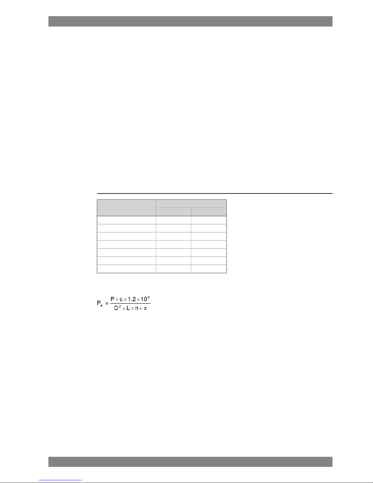
The mean effective pressure Pecan be calculated using the following formula:
where:
mean effective pressure [bar]Pe=
output per cylinder [kW]P =
engine speed [r/min]n =
cylinder diameter [mm]D =
length of piston stroke [mm]L =
operating cycle (4)c =
Wärtsilä 46F Product Guide - a19 - 1 December 2017 1-1
1. Main Data and OutputsWärtsilä 46F Product Guide
Page 8

1.2 Reference conditions
The output is available up to an air temperature of max. 45°C. For higher temperatures, the
output has to be reduced according to the formula stated in ISO 3046-1:2002 (E).
The specific fuel oil consumption is stated in the chapter Technical data. The stated specific
fuel oil consumption applies to engines with engine driven pumps, operating in ambient
conditions according to ISO 15550:2002 (E). The ISO standard reference conditions are:
100 kPatotal barometric pressure
25°Cair temperature
30%relative humidity
25°Ccharge air coolant temperature
Correction factors for the fuel oil consumption in other ambient conditions are given in standard
ISO 15550:2002 (E).
1.3 Operation in inclined position
Max. inclination angles at which the engine will operate satisfactorily.
15°
● Permanent athwart ship inclinations
22.5°
● Temporary athwart ship inclinations
10°
● Permanent fore-and-aft inclinations
1-2 Wärtsilä 46F Product Guide - a19 - 1 December 2017
Wärtsilä 46F Product Guide1. Main Data and Outputs
Page 9
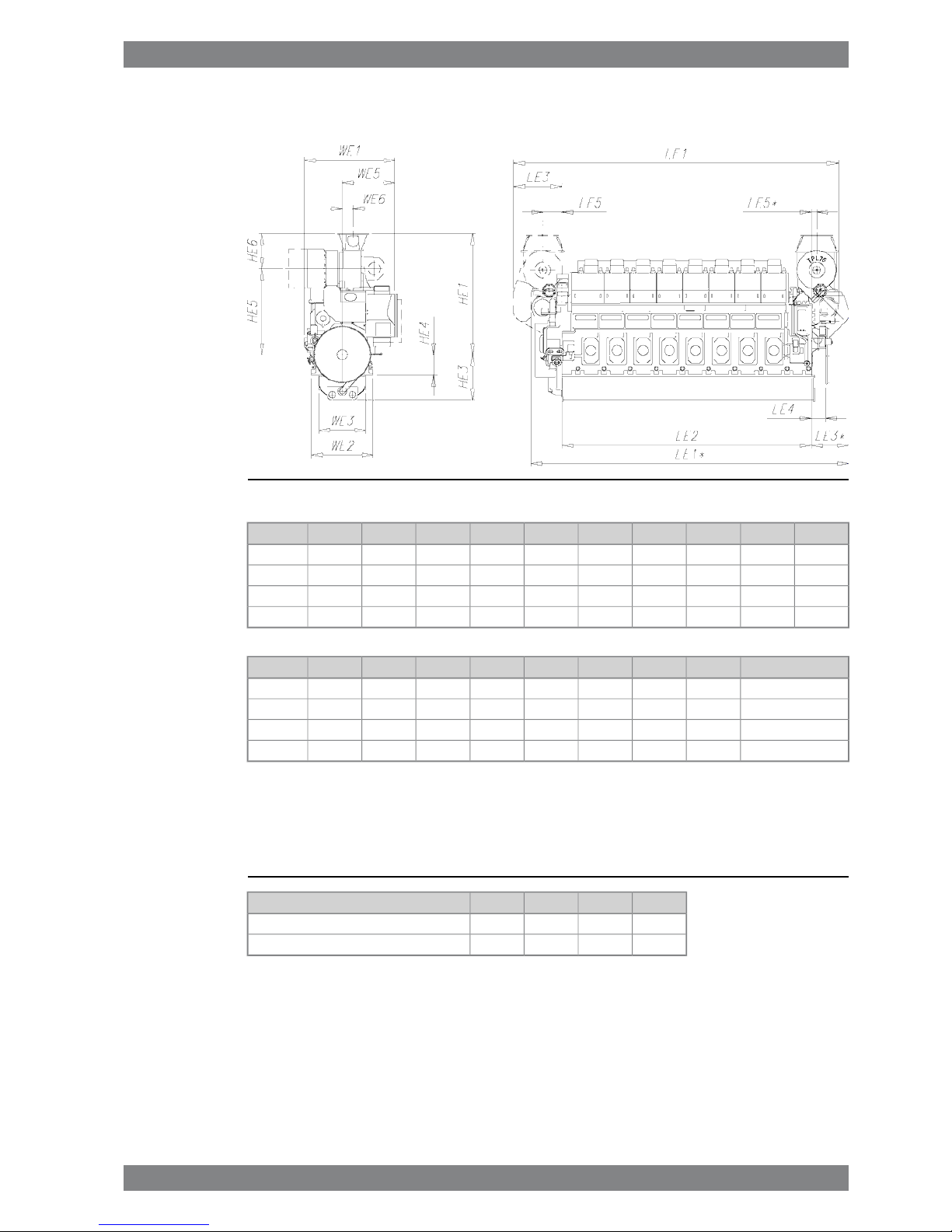
1.4 Dimensions and weights
Fig 1-1 In-line engines (DAAE012051c)
HE3HE1LE5LE5*LE4LE3LE3*LE2LE1LE1*Engine
14303500690180460155013206170862084706L46F
14303800800180460155014656990944094357L46F
1430380080018046015501465781010260102558L46F
1430380080018046015501465863011080110759L46F
Weight [ton]WE6WE5WE3WE2WE1HE6HE5HE4Engine
97385153514801940290579027106506L46F
1133401760148019403130110027006507L46F
1243401760148019403130110027006508L46F
1403401760148019403130110027006509L46F
* Turbocharger at flywheel end
All dimensions in mm. The weights are dry weights of rigidly mounted engines without flywheel.
Table 1-2 Additional weights [ton]:
9L46F8L46F7L46F6L46FItem
1...21...21...21...2Flywheel
3333Flexible mounting (without limiters)
Wärtsilä 46F Product Guide - a19 - 1 December 2017 1-3
1. Main Data and OutputsWärtsilä 46F Product Guide
Page 10
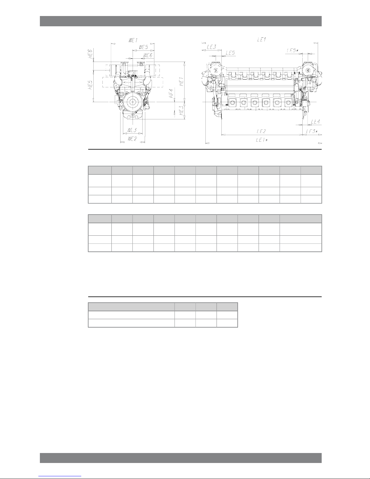
Fig 1-2 V-engines (DAAE075826B)
HE3HE1LE5LE5*LE4LE3LE3*LE2LE1LE1*Engine
16203765* /
3770
7745204601952183076001028410945
12V46F
16204234872-4852347-865011728-14V46F
16204234872-4852347-970012871-16V46F
Weight [ton]WE6WE5WE3WE2WE1HE6HE5HE4Engine
1777602825* /
3150
182022904040* /
4026
7902975* /
2980
800
12V46F
21689231501820229046781100313480014V46F
23389231501820229046781100313480016V46F
* Turbocharger in flywheel end
All dimensions in mm. The weights are dry weights of rigidly mounted engines without flywheel.
Table 1-3 Additional weights [ton]:
16V46F14V46F12V46FItem
1...21...21...2Flywheel
333Flexible mounting (without limiters)
1-4 Wärtsilä 46F Product Guide - a19 - 1 December 2017
Wärtsilä 46F Product Guide1. Main Data and Outputs
Page 11
2. Operating Ranges
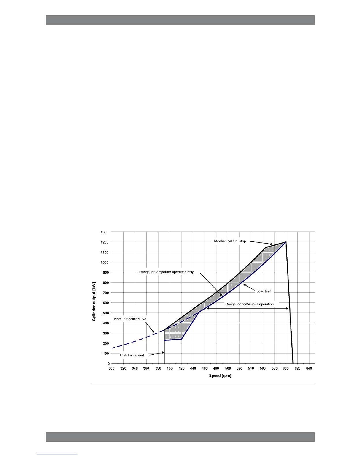
2.1 Engine operating range
Running below nominal speed the load must be limited according to the diagrams in this
chapter in order to maintain engine operating parameters within acceptable limits. Operation
in the shaded area is permitted only temporarily during transients. Minimum speed is indicated
in the diagram, but project specific limitations may apply.
2.1.1 Controllable pitch propellers
An automatic load control system is required to protect the engine from overload. The load
control reduces the propeller pitch automatically, when a pre-programmed load versus speed
curve (“engine limit curve”) is exceeded, overriding the combinator curve if necessary. The
engine load is derived from fuel rack position and actual engine speed (not speed demand).
The propulsion control must also include automatic limitation of the load increase rate.
Maximum loading rates can be found later in this chapter.
The propeller efficiency is highest at design pitch. It is common practice to dimension the
propeller so that the specified ship speed is attained with design pitch, nominal engine speed
and 85% output in the specified loading condition. The power demand from a possible shaft
generator or PTO must be taken into account. The 15% margin is a provision for weather
conditions and fouling of hull and propeller. An additional engine margin can be applied for
most economical operation of the engine, or to have reserve power.
Fig 2-1 Operating field for CP Propeller, IMO Tier 2, 1200 kW/cyl, 600 rpm
Wärtsilä 46F Product Guide - a19 - 1 December 2017 2-1
2. Operating RangesWärtsilä 46F Product Guide
Page 12
2.2 Loading capacity
Controlled load increase is essential for highly supercharged diesel engines, because the
turbocharger needs time to accelerate before it can deliver the required amount of air. Sufficient
time to achieve even temperature distribution in engine components must also be ensured.
This is especially important for larger engines.
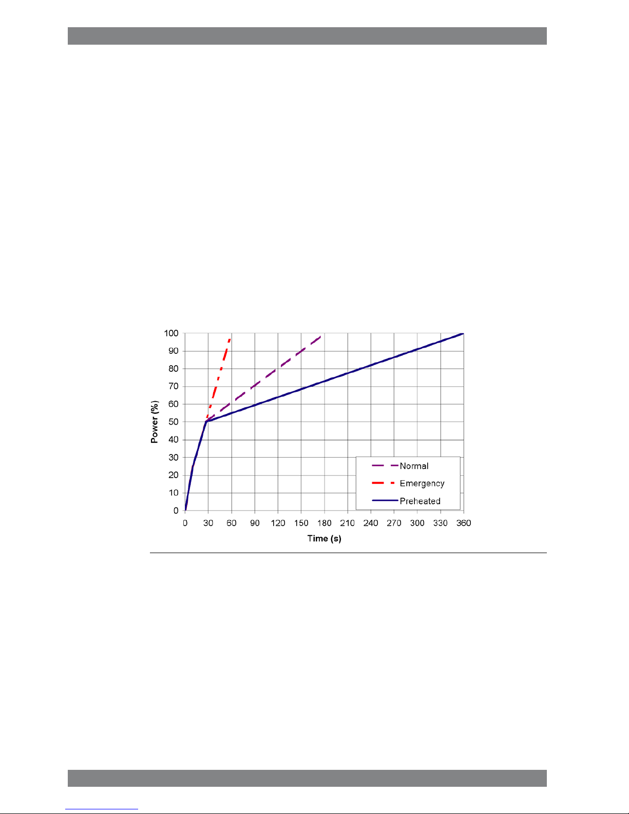
If the control system has only one load increase ramp, then the ramp for a preheated engine
should be used. The HT-water temperature in a preheated engine must be at least 60 ºC,
preferably 70 ºC, and the lubricating oil temperature must be at least 40 ºC.
The ramp for normal loading applies to engines that have reached normal operating
temperature.
Emergency loading may only be possible by activating an emergency function, which generates
visual and audible alarms in the control room and on the bridge.
The load should always be applied gradually in normal operation. Class rules regarding load
acceptance capability of diesel generators should not be interpreted as guidelines on how to
apply load in normal operation. The class rules define what the engine must be capable of, if
an unexpected event causes a sudden load step.
2.2.1 Mechanical propulsion, controllable pitch propeller (CPP)
Fig 2-2 Maximum load increase rates for variable speed engines
If minimum smoke during load increase is a major priority, slower loading rate than in the
diagram can be necessary below 50% load.
In normal operation the load should not be reduced from 100% to 0% in less than 15 seconds.
When absolutely necessary, the load can be reduced as fast as the pitch setting system can
react (overspeed due to windmilling must be considered for high speed ships).
2-2 Wärtsilä 46F Product Guide - a19 - 1 December 2017
Wärtsilä 46F Product Guide2. Operating Ranges
Page 13
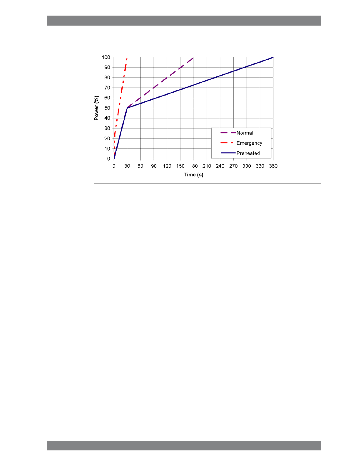
2.2.2 Diesel electric propulsion
Fig 2-3 Maximum load increase rates for engines operating at nominal speed
In normal operation the load should not be reduced from 100% to 0% in less than 15 seconds.
In an emergency situation the full load can be thrown off instantly.
The maximum deviation from steady state speed is less than 10%, when applying load
according to the emergency loading ramp. Load increase according to the normal ramp
correspondingly results in less than 3% speed deviation.
2.2.2.1 Maximum instant load steps
The electrical system must be designed so that tripping of breakers can be safely handled.
This requires that the engines are protected from load steps exceeding their maximum load
acceptance capability. The maximum permissible load step for an engine that has attained
normal operating temperature is 33% MCR. The resulting speed drop is less than 10% and
the recovery time to within 1% of the steady state speed at the new load level is max. 5
seconds.
When electrical power is restored after a black-out, consumers are reconnected in groups,
which may cause significant load steps. The engine must be allowed to recover for at least
10 seconds before applying the following load step, if the load is applied in maximum steps.
2.2.2.2 Start-up time
A diesel generator typically reaches nominal speed in about 25 seconds after the start signal.
The acceleration is limited by the speed control to minimise smoke during start-up.
2.3 Operation at low load and idling
The engine can be started, stopped and operated on heavy fuel under all operating conditions.
Continuous operation on heavy fuel is preferred rather than changing over to diesel fuel at low
load operation and manoeuvring. The following recommendations apply:
Absolute idling (declutched main engine, disconnected generator)
● Maximum 10 minutes if the engine is to be stopped after the idling. 3 minutes idling before
stop is recommended.
Wärtsilä 46F Product Guide - a19 - 1 December 2017 2-3
2. Operating RangesWärtsilä 46F Product Guide
Page 14

● Maximum 6 hours if the engine is to be loaded after the idling.
Operation below 20 % load
● Maximum 100 hours continuous operation. At intervals of 100 operating hours the engine
must be loaded to minimum 70 % of the rated output.
Operation above 20 % load
● No restrictions.
2.4 Low air temperature
In cold conditions the following minimum inlet air temperatures apply:
● Starting + 5ºC
● Idling - 5ºC
● High load - 10ºC
The two-stage charge air cooler is useful for heating of the charge air during prolonged low
load operation in cold conditions. Sustained operation between 0 and 40% load can however
require special provisions in cold conditions to prevent too low HT-water temperature. If
necessary, the preheating arrangement can be designed to heat the running engine (capacity
to be checked).
For further guidelines, see chapter Combustion air system design.
2-4 Wärtsilä 46F Product Guide - a19 - 1 December 2017
Wärtsilä 46F Product Guide2. Operating Ranges
Page 15
3. Technical Data
3.1 Introduction
This chapter contains technical data of the engine (heat balance, flows, pressures etc.) for
design of auxiliary systems. Further design criteria for external equipment and system layouts
are presented in the respective chapter.
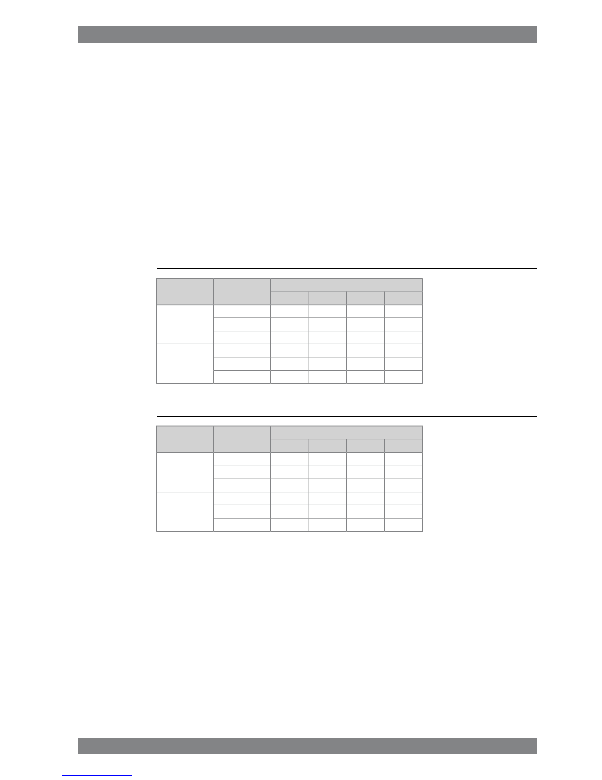
3.1.1 Engine driven pumps
The fuel consumption stated in the technical data tables is with engine driven pumps. The
increase in fuel consumption with engine driven pumps is given in the table below; correction
in g/kWh.
Table 3-1 Constant speed engines
Engine load [%]Engine driven
pumps
Application
507585100
-2.4-1.5-1.3-1.1Lube oil
Inline -0.7-0.4-0.4-0.3LT Water
-0.7-0.4-0.4-0.3HT Water
-1.6-1.2-1.0-1.0Lube oil
V-engine -0.3-0.3-0.3-0.3LT Water
-0.3-0.3-0.3-0.3HT Water
Table 3-2 Variable speed engines
Engine load [%]Engine driven
pumps
Application
507585100
-1.9-1.4-1.3-1.2Lube oil
Inline -0.3-0.3-0.3-0.3LT Water
-0.3-0.3-0.3-0.3HT Water
-1.6-1.2-1.0-1.0Lube oil
V-engine -0.3-0.3-0.3-0.3LT Water
-0.3-0.3-0.3-0.3HT Water
Wärtsilä 46F Product Guide - a19 - 1 December 2017 3-1
3. Technical DataWärtsilä 46F Product Guide
Page 16
3.2 Wärtsilä 6L46F
DEMEWärtsilä 6L46F
12001200kWCylinder output
600600rpmEngine speed
72007200kWEngine output
2.492.49MPaMean effective pressure
Combustion air system (Note 1)
12.412.4kg/sFlow at 100% load
4545°CTemperature at turbocharger intake, max. (TE 600)
5050°CTemperature after air cooler, nom. (TE 601)
Exhaust gas system (Note 2)
13.0813.08kg/sFlow at 100% load
11.711.4kg/sFlow at 85% load
11.710.8kg/sFlow at 75% load
9.427.44kg/sFlow at 50% load
368368°CTemp. after turbo, 100% load (TE 517)
318322°CTemp. after turbo, 85% load (TE 517)
310323°CTemp. after turbo, 75% load (TE 517)
275327°CTemp. after turbo, 50% load (TE 517)
33kPaBackpressure, max.
927927mmCalculated pipe diameter for 35 m/s
Heat balance at 100% load (Note 3)
846846kWJacket water, HT-circuit
14881488kWCharge air, HT-circuit
762762kWCharge air, LT-circuit
756756kWLubricating oil, LT-circuit
210210kWRadiation
Fuel system (Note 4)
880...930880...930kPaPressure before injection pumps (PT 101) at 100% load - HFO
900...950900...950kPaPressure before injection pumps (PT 101) at 85% load - HFO
4.9...5.44.9...5.4m3/hFlow to engine, approx. - HFO
16...2416...24cStHFO viscosity before engine
140140°CMax. HFO temperature before engine (TE 101)
2.02.0cStMDF viscosity, min.
4545°CMax. MDF temperature before engine (TE 101)
4.54.5kg/hLeak fuel quantity (HFO), clean fuel at 100% load
22.522.5kg/hLeak fuel quantity (MDF), clean fuel at 100% load
179.6179.6g/kWhFuel consumption at 100% load
174.7173.4g/kWhFuel consumption at 85% load
183.6177.9g/kWhFuel consumption at 75% load
191.5181.0g/kWhFuel consumption at 50% load
Lubricating oil system
500500kPaPressure before bearings, nom. (PT 201)
3-2 Wärtsilä 46F Product Guide - a19 - 1 December 2017
Wärtsilä 46F Product Guide3. Technical Data
Page 17
DEMEWärtsilä 6L46F
12001200kWCylinder output
600600rpmEngine speed
800800kPaPressure after pump, max.
4040kPaSuction ability main pump, including pipe loss, max.
8080kPaPriming pressure, nom. (PT 201)
5656°CTemperature before bearings, nom. (TE 201)
7575°CTemperature after engine, approx.
175191m3/hPump capacity (main), engine driven
158191m3/hPump capacity (main), electrically driven
130130m3/hOil flow through engine
3535m3/hPriming pump capacity
13.013.0m
3
Oil tank volume in separate system, min
0.70.7g/kWhOil consumption at 100% load, approx.
13501350l/minCrankcase ventilation flow rate at full load
0.40.4kPaCrankcase ventilation backpressure, max.
9.59.5lOil volume in turning device
1.71.7lOil volume in speed governor
High temperature cooling water system
250 + static250 + statickPaPressure at engine, after pump, nom. (PT 401)
530530kPaPressure at engine, after pump, max. (PT 401)
7474°CTemperature before cylinders, approx. (TE 401)
91...9591...95°CTemperature after charge air cooler, nom.
115115m3/hCapacity of engine driven pump, nom.
150150kPaPressure drop over engine, total
100100kPaPressure drop in external system, max.
70...15070...150kPaPressure from expansion tank
1.01.0m
3
Water volume in engine
Low temperature cooling water system
250 + static250 + statickPaPressure at engine, after pump, nom. (PT 451)
530530kPaPressure at engine, after pump, max. (PT 451)
3838°CTemperature before engine, max. (TE 451)
2525°CTemperature before engine, min. (TE 451)
115115m3/hCapacity of engine driven pump, nom.
5050kPaPressure drop over charge air cooler
2020kPaPressure drop over built-on lube oil cooler
3030kPaPressure drop over built-on temp. control valve
150150kPaPressure drop in external system, max.
70 ... 15070 ... 150kPaPressure from expansion tank
0.30.3m
3
Water volume in engine
Starting air system (Note 5)
30003000kPaPressure, nom. (PT 301)
15001500kPaPressure at engine during start, min. (20°C)
30003000kPaPressure, max. (PT 301)
18001800kPaLow pressure limit in air vessels
6.06.0Nm
3
Consumption per start at 20°C (successful start)
Wärtsilä 46F Product Guide - a19 - 1 December 2017 3-3
3. Technical DataWärtsilä 46F Product Guide
Page 18

DEMEWärtsilä 6L46F
12001200kWCylinder output
600600rpmEngine speed
7.07.0Nm
3
Consumption per start at 20°C, (with slowturn)
Notes:
At ISO 15550 conditions (ambient air temperature 25°C, LT-water 25°C) and 100% load. Flow tolerance 5%.Note
1
At ISO 15550 conditions (ambient air temperature 25°C, LT-water 25°C). Flow tolerance 5% and temperature tolerance
15°C.
Note
2
At ISO 15550 conditions (ambient air temperature 25°C, LT-water 25°C) and 100% load. Tolerance for cooling water heat
10%, tolerance for radiation heat 30%. Fouling factors and a margin to be taken into account when dimensioning heat exchangers.
Note
3
According to ISO 15550, lower calorific value 42700 kJ/kg, with engine driven pumps (two cooling water + one lubricating
oil pumps). Tolerance 5%. The fuel consumption at 85 % load is guaranteed and the values at other loads are given for indication only.
Note
4
At manual starting the consumption may be 2...3 times lower.Note
5
ME = Engine driving propeller, variable speed
DE = Engine driving generator
Subject to revision without notice.
3-4 Wärtsilä 46F Product Guide - a19 - 1 December 2017
Wärtsilä 46F Product Guide3. Technical Data
Page 19

3.3 Wärtsilä 7L46F
DEMEWärtsilä 7L46F
12001200kWCylinder output
600600rpmEngine speed
84008400kWEngine output
2.492.49MPaMean effective pressure
Combustion air system (Note 1)
14.614.6kg/sFlow at 100% load
4545°CTemperature at turbocharger intake, max. (TE 600)
5050°CTemperature after air cooler, nom. (TE 601)
Exhaust gas system (Note 2)
15.2615.26kg/sFlow at 100% load
13.6513.3kg/sFlow at 85% load
13.6512.6kg/sFlow at 75% load
10.998.68kg/sFlow at 50% load
368368°CTemp. after turbo, 100% load (TE 517)
318322°CTemp. after turbo, 85% load (TE 517)
310323°CTemp. after turbo, 75% load (TE 517)
275327°CTemp. after turbo, 50% load (TE 517)
33kPaBackpressure, max.
10011001mmCalculated pipe diameter for 35 m/s
Heat balance at 100% load (Note 3)
987987kWJacket water, HT-circuit
17361736kWCharge air, HT-circuit
889889kWCharge air, LT-circuit
882882kWLubricating oil, LT-circuit
245245kWRadiation
Fuel system (Note 4)
880...930880...930kPaPressure before injection pumps (PT 101) at 100% load - HFO
900...950900...950kPaPressure before injection pumps (PT101) at 85% load - HFO
5.7...6.35.7...6.3m3/hFlow to engine, approx - HFO
16...2416...24cStHFO viscosity before engine
140140°CMax. HFO temperature before engine (TE 101)
2.02.0cStMDF viscosity, min.
4545°CMax. MDF temperature before engine (TE 101)
5.25.2kg/hLeak fuel quantity (HFO), clean fuel at 100% load
26.526.5kg/hLeak fuel quantity (MDF), clean fuel at 100% load
179.6179.6g/kWhFuel consumption at 100% load
174.7173.4g/kWhFuel consumption at 85% load
183.6177.9g/kWhFuel consumption at 75% load
191.5181.0g/kWhFuel consumption at 50% load
Lubricating oil system
500500kPaPressure before bearings, nom. (PT 201)
Wärtsilä 46F Product Guide - a19 - 1 December 2017 3-5
3. Technical DataWärtsilä 46F Product Guide
Page 20

DEMEWärtsilä 7L46F
12001200kWCylinder output
600600rpmEngine speed
800800kPaPressure after pump, max.
4040kPaSuction ability main pump, including pipe loss, max.
8080kPaPriming pressure, nom. (PT 201)
5656°CTemperature before bearings, nom. (TE 201)
7575°CTemperature after engine, approx.
191207m3/hPump capacity (main), engine driven
179207m3/hPump capacity (main), electrically driven
150150m3/hOil flow through engine
4545m3/hPriming pump capacity
15.015.0m
3
Oil tank volume in separate system, min
0.70.7g/kWhOil consumption at 100% load, approx.
16001600l/minCrankcase ventilation flow rate at full load
0.40.4kPaCrankcase ventilation backpressure, max.
9.59.5lOil volume in turning device
1.71.7lOil volume in speed governor
High temperature cooling water system
250 + static250 + statickPaPressure at engine, after pump, nom. (PT 401)
530530kPaPressure at engine, after pump, max. (PT 401)
7474°CTemperature before cylinders, approx. (TE 401)
91...9591...95°CTemperature after charge air cooler, nom.
150150m3/hCapacity of engine driven pump, nom.
150150kPaPressure drop over engine, total
100100kPaPressure drop in external system, max.
70...15070...150kPaPressure from expansion tank
1.31.3m
3
Water volume in engine
Low temperature cooling water system
250 + static250 + statickPaPressure at engine, after pump, nom. (PT 451)
530530kPaPressure at engine, after pump, max. (PT 451)
3838°CTemperature before engine, max. (TE 451)
2525°CTemperature before engine, min. (TE 451)
150150m3/hCapacity of engine driven pump, nom.
5050kPaPressure drop over charge air cooler
2020kPaPressure drop over built-on lube oil cooler
3030kPaPressure drop over built-on temp. control valve
150150kPaPressure drop in external system, max.
70 ... 15070 ... 150kPaPressure from expansion tank
0.40.4m
3
Water volume in engine
Starting air system (Note 5)
30003000kPaPressure, nom. (PT 301)
15001500kPaPressure at engine during start, min. (20°C)
30003000kPaPressure, max. (PT 301)
18001800kPaLow pressure limit in air vessels
7.07.0Nm
3
Consumption per start at 20°C (successful start)
3-6 Wärtsilä 46F Product Guide - a19 - 1 December 2017
Wärtsilä 46F Product Guide3. Technical Data
Page 21

DEMEWärtsilä 7L46F
12001200kWCylinder output
600600rpmEngine speed
8.08.0Nm
3
Consumption per start at 20°C, (with slowturn)
Notes:
At ISO 15550 conditions (ambient air temperature 25°C, LT-water 25°C) and 100% load. Flow tolerance 5%.Note
1
At ISO 15550 conditions (ambient air temperature 25°C, LT-water 25°C). Flow tolerance 5% and temperature tolerance
15°C.
Note
2
At ISO 15550 conditions (ambient air temperature 25°C, LT-water 25°C) and 100% load. Tolerance for cooling water heat
10%, tolerance for radiation heat 30%. Fouling factors and a margin to be taken into account when dimensioning heat exchangers.
Note
3
According to ISO 15550, lower calorific value 42700 kJ/kg, with engine driven pumps (two cooling water + one lubricating
oil pumps). Tolerance 5%. The fuel consumption at 85 % load is guaranteed and the values at other loads are given for indication only.
Note
4
At manual starting the consumption may be 2...3 times lower.Note
5
ME = Engine driving propeller, variable speed
DE = Engine driving generator
Subject to revision without notice.
Wärtsilä 46F Product Guide - a19 - 1 December 2017 3-7
3. Technical DataWärtsilä 46F Product Guide
Page 22

3.4 Wärtsilä 8L46F
DE
IMO Tier 2
ME
IMO Tier 2
Wärtsilä 8L46F
12001200kWCylinder output
600600rpmEngine speed
96009600kWEngine output
2.492.49MPaMean effective pressure
Combustion air system (Note 1)
16.616.6kg/sFlow at 100% load
4545°CTemperature at turbocharger intake, max. (TE 600)
5050°CTemperature after air cooler, nom. (TE 601)
Exhaust gas system (Note 2)
17.4417.44kg/sFlow at 100% load
15.615.2kg/sFlow at 85% load
15.614.4kg/sFlow at 75% load
12.569.92kg/sFlow at 50% load
368368°CTemp. after turbo, 100% load (TE 517)
318322°CTemp. after turbo, 85% load (TE 517)
310323°CTemp. after turbo, 75% load (TE 517)
275327°CTemp. after turbo, 50% load (TE 517)
33kPaBackpressure, max.
10701070mmCalculated pipe diameter for 35 m/s
Heat balance at 100% load (Note 3)
11281128kWJacket water, HT-circuit
19841984kWCharge air, HT-circuit
10161016kWCharge air, LT-circuit
10081008kWLubricating oil, LT-circuit
280280kWRadiation
Fuel system (Note 4)
880...930880...930kPaPressure before injection pumps (PT 101) at 100% load - HFO
900...950900...950kPaPressure before injection pumps (PT101) at 85% load - HFO
6.5...7.26.5...7.2m3/hFlow to engine, approx HFO
16...2416...24cStHFO viscosity before engine
140140°CMax. HFO temperature before engine (TE 101)
2.02.0cStMDF viscosity, min.
4545°CMax. MDF temperature before engine (TE 101)
6.06.0kg/hLeak fuel quantity (HFO), clean fuel at 100% load
30.030.0kg/hLeak fuel quantity (MDF), clean fuel at 100% load
179.6179.6g/kWhFuel consumption at 100% load
174.7173.4g/kWhFuel consumption at 85% load
183.6177.9g/kWhFuel consumption at 75% load
191.5181.0g/kWhFuel consumption at 50% load
Lubricating oil system
500500kPaPressure before bearings, nom. (PT 201)
3-8 Wärtsilä 46F Product Guide - a19 - 1 December 2017
Wärtsilä 46F Product Guide3. Technical Data
Page 23
DE
IMO Tier 2
ME
IMO Tier 2
Wärtsilä 8L46F
12001200kWCylinder output
600600rpmEngine speed
800800kPaPressure after pump, max.
4040kPaSuction ability main pump, including pipe loss, max.
8080kPaPriming pressure, nom. (PT 201)
5656°CTemperature before bearings, nom. (TE 201)
7575°CTemperature after engine, approx.
207228m3/hPump capacity (main), engine driven
198228m3/hPump capacity (main), electrically driven
170170m3/hOil flow through engine
4545m3/hPriming pump capacity
17.017.0m
3
Oil tank volume in separate system, min
0.70.7g/kWhOil consumption at 100% load, approx.
17001700l/minCrankcase ventilation flow rate at full load
0.40.4kPaCrankcase ventilation backpressure, max.
9.59.5lOil volume in turning device
1.71.7lOil volume in speed governor
High temperature cooling water system
250 + static250 + statickPaPressure at engine, after pump, nom. (PT 401)
530530kPaPressure at engine, after pump, max. (PT 401)
7474°CTemperature before cylinders, approx. (TE 401)
91...9591...95°CTemperature after charge air cooler, nom.
150150m3/hCapacity of engine driven pump, nom.
150150kPaPressure drop over engine, total
100100kPaPressure drop in external system, max.
70...15070...150kPaPressure from expansion tank
1.41.4m
3
Water volume in engine
Low temperature cooling water system
250 + static250 + statickPaPressure at engine, after pump, nom. (PT 451)
530530kPaPressure at engine, after pump, max. (PT 451)
3838°CTemperature before engine, max. (TE 451)
2525°CTemperature before engine, min. (TE 451)
150150m3/hCapacity of engine driven pump, nom.
5050kPaPressure drop over charge air cooler
2020kPaPressure drop over built-on lube oil cooler
3030kPaPressure drop over built-on temp. control valve
150150kPaPressure drop in external system, max.
70 ... 15070 ... 150kPaPressure from expansion tank
0.40.4m
3
Water volume in engine
Starting air system (Note 5)
30003000kPaPressure, nom. (PT 301)
15001500kPaPressure at engine during start, min. (20°C)
30003000kPaPressure, max. (PT 301)
18001800kPaLow pressure limit in air vessels
8.08.0Nm
3
Consumption per start at 20°C (successful start)
Wärtsilä 46F Product Guide - a19 - 1 December 2017 3-9
3. Technical DataWärtsilä 46F Product Guide
Page 24

DE
IMO Tier 2
ME
IMO Tier 2
Wärtsilä 8L46F
12001200kWCylinder output
600600rpmEngine speed
9.09.0Nm
3
Consumption per start at 20°C, (with slowturn)
Notes:
At ISO 15550 conditions (ambient air temperature 25°C, LT-water 25°C) and 100% load. Flow tolerance 5%.Note
1
At ISO 15550 conditions (ambient air temperature 25°C, LT-water 25°C). Flow tolerance 5% and temperature tolerance
15°C.
Note
2
At ISO 15550 conditions (ambient air temperature 25°C, LT-water 25°C) and 100% load. Tolerance for cooling water heat
10%, tolerance for radiation heat 30%. Fouling factors and a margin to be taken into account when dimensioning heat exchangers.
Note
3
According to ISO 15550, lower calorific value 42700 kJ/kg, with engine driven pumps (two cooling water + one lubricating
oil pumps). Tolerance 5%. The fuel consumption at 85 % load is guaranteed and the values at other loads are given for indication only.
Note
4
At manual starting the consumption may be 2...3 times lower.Note
5
ME = Engine driving propeller, variable speed
DE = Engine driving generator
Subject to revision without notice.
3-10 Wärtsilä 46F Product Guide - a19 - 1 December 2017
Wärtsilä 46F Product Guide3. Technical Data
Page 25
3.5 Wärtsilä 9L46F
DE
IMO Tier 2
ME
IMO Tier 2
Wärtsilä 9L46F
12001200kWCylinder output
600600rpmEngine speed
1080010800kWEngine output
2.492.49MPaMean effective pressure
Combustion air system (Note 1)
18.818.8kg/sFlow at 100% load
4545°CTemperature at turbocharger intake, max. (TE 600)
5050°CTemperature after air cooler, nom. (TE 601)
Exhaust gas system (Note 2)
19.6219.62kg/sFlow at 100% load
17.5517.1kg/sFlow at 85% load
17.5516.2kg/sFlow at 75% load
14.1311.16kg/sFlow at 50% load
368368°CTemp. after turbo, 100% load (TE 517)
318322°CTemp. after turbo, 85% load (TE 517)
310323°CTemp. after turbo, 75% load (TE 517)
275327°CTemp. after turbo, 50% load (TE 517)
33kPaBackpressure, max.
11351135mmCalculated pipe diameter for 35 m/s
Heat balance at 100% load (Note 3)
12691269kWJacket water, HT-circuit
22322232kWCharge air, HT-circuit
11431143kWCharge air, LT-circuit
11341134kWLubricating oil, LT-circuit
315315kWRadiation
Fuel system (Note 4)
880...930880...930kPaPressure before injection pumps (PT 101) at 100% load - HFO
900...950900...950kPaPressure before injection pumps (PT101) at 85% load -HFO
7.3...8.17.3...8.1m3/hFlow to engine, approx - HFO
16...2416...24cStHFO viscosity before engine
140140°CMax. HFO temperature before engine (TE 101)
2.02.0cStMDF viscosity, min.
4545°CMax. MDF temperature before engine (TE 101)
6.86.8kg/hLeak fuel quantity (HFO), clean fuel at 100% load
34.034.0kg/hLeak fuel quantity (MDF), clean fuel at 100% load
179.6179.6g/kWhFuel consumption at 100% load
174.7173.4g/kWhFuel consumption at 85% load
183.6177.9g/kWhFuel consumption at 75% load
191.5181.0g/kWhFuel consumption at 50% load
Lubricating oil system
500500kPaPressure before bearings, nom. (PT 201)
Wärtsilä 46F Product Guide - a19 - 1 December 2017 3-11
3. Technical DataWärtsilä 46F Product Guide
Page 26

DE
IMO Tier 2
ME
IMO Tier 2
Wärtsilä 9L46F
12001200kWCylinder output
600600rpmEngine speed
800800kPaPressure after pump, max.
4040kPaSuction ability main pump, including pipe loss, max.
8080kPaPriming pressure, nom. (PT 201)
5656°CTemperature before bearings, nom. (TE 201)
7575°CTemperature after engine, approx.
228253m3/hPump capacity (main), engine driven
218253m3/hPump capacity (main), electrically driven
190190m3/hOil flow through engine
5050m3/hPriming pump capacity
19.019.0m
3
Oil tank volume in separate system, min
0.70.7g/kWhOil consumption at 100% load, approx.
18001800l/minCrankcase ventilation flow rate at full load
0.40.4kPaCrankcase ventilation backpressure, max.
70.070.0lOil volume in turning device
1.71.7lOil volume in speed governor
High temperature cooling water system
250 + static250 + statickPaPressure at engine, after pump, nom. (PT 401)
530530kPaPressure at engine, after pump, max. (PT 401)
7474°CTemperature before cylinders, approx. (TE 401)
91...9591...95°CTemperature after charge air cooler, nom.
180180m3/hCapacity of engine driven pump, nom.
150150kPaPressure drop over engine, total
100100kPaPressure drop in external system, max.
70...15070...150kPaPressure from expansion tank
1.51.5m
3
Water volume in engine
Low temperature cooling water system
250 + static250 + statickPaPressure at engine, after pump, nom. (PT 451)
530530kPaPressure at engine, after pump, max. (PT 451)
3838°CTemperature before engine, max. (TE 451)
2525°CTemperature before engine, min. (TE 451)
180180m3/hCapacity of engine driven pump, nom.
5050kPaPressure drop over charge air cooler
2020kPaPressure drop over built-on lube oil cooler
3030kPaPressure drop over built-on temp. control valve
150150kPaPressure drop in external system, max.
70 ... 15070 ... 150kPaPressure from expansion tank
0.50.5m
3
Water volume in engine
Starting air system (Note 5)
30003000kPaPressure, nom. (PT 301)
15001500kPaPressure at engine during start, min. (20°C)
30003000kPaPressure, max. (PT 301)
18001800kPaLow pressure limit in air vessels
9.09.0Nm
3
Consumption per start at 20°C (successful start)
3-12 Wärtsilä 46F Product Guide - a19 - 1 December 2017
Wärtsilä 46F Product Guide3. Technical Data
Page 27

DE
IMO Tier 2
ME
IMO Tier 2
Wärtsilä 9L46F
12001200kWCylinder output
600600rpmEngine speed
10.010.0Nm
3
Consumption per start at 20°C, (with slowturn)
Notes:
At ISO 15550 conditions (ambient air temperature 25°C, LT-water 25°C) and 100% load. Flow tolerance 5%.Note
1
At ISO 15550 conditions (ambient air temperature 25°C, LT-water 25°C). Flow tolerance 5% and temperature tolerance
15°C.
Note
2
At ISO 15550 conditions (ambient air temperature 25°C, LT-water 25°C) and 100% load. Tolerance for cooling water heat
10%, tolerance for radiation heat 30%. Fouling factors and a margin to be taken into account when dimensioning heat exchangers.
Note
3
According to ISO 15550, lower calorific value 42700 kJ/kg, with engine driven pumps (two cooling water + one lubricating
oil pumps). Tolerance 5%. The fuel consumption at 85 % load is guaranteed and the values at other loads are given for indication only.
Note
4
At manual starting the consumption may be 2...3 times lower.Note
5
ME = Engine driving propeller, variable speed
DE = Engine driving generator
Subject to revision without notice.
Wärtsilä 46F Product Guide - a19 - 1 December 2017 3-13
3. Technical DataWärtsilä 46F Product Guide
Page 28
3.6 Wärtsilä 12V46F
DE
IMO Tier 2
ME
IMO Tier 2
Wärtsilä 12V46F
12001200kWCylinder output
600600rpmEngine speed
1440014400kWEngine output
2.492.49MPaMean effective pressure
Combustion air system (Note 1)
25.025.0kg/sFlow at 100% load
4545°CTemperature at turbocharger intake, max. (TE 600)
5050°CTemperature after air cooler, nom. (TE 601)
Exhaust gas system (Note 2)
26.1626.16kg/sFlow at 100% load
23.422.8kg/sFlow at 85% load
23.421.6kg/sFlow at 75% load
18.8414.88kg/sFlow at 50% load
366366°CTemp. after turbo, 100% load (TE 517)
316320°CTemp. after turbo, 85% load (TE 517)
309322°CTemp. after turbo, 75% load (TE 517)
273325°CTemp. after turbo, 50% load (TE 517)
33kPaBackpressure, max.
13091309mmCalculated pipe diameter for 35 m/s
Heat balance at 100% load (Note 3)
16321632kWJacket water, HT-circuit
29762976kWCharge air, HT-circuit
15241524kWCharge air, LT-circuit
14641464kWLubricating oil, LT-circuit
420420kWRadiation
Fuel system (Note 4)
880...930880...930kPaPressure before injection pumps (PT 101) at 100% load - HFO
900...950900...950kPaPressure before injection pumps (PT101) at 85% load - HFO
9.8...10.89.8...10.8m3/hFlow to engine, approx - HFO
16...2416...24cStHFO viscosity before engine
140140°CMax. HFO temperature before engine (TE 101)
2.02.0cStMDF viscosity, min.
4545°CMax. MDF temperature before engine (TE 101)
9.09.0kg/hLeak fuel quantity (HFO), clean fuel at 100% load
45.045.0kg/hLeak fuel quantity (MDF), clean fuel at 100% load
178.7178.7g/kWhFuel consumption at 100% load
173.7172.5g/kWhFuel consumption at 85% load
182.7177.0g/kWhFuel consumption at 75% load
190.6180.1g/kWhFuel consumption at 50% load
Lubricating oil system
500500kPaPressure before bearings, nom. (PT 201)
3-14 Wärtsilä 46F Product Guide - a19 - 1 December 2017
Wärtsilä 46F Product Guide3. Technical Data
Page 29

DE
IMO Tier 2
ME
IMO Tier 2
Wärtsilä 12V46F
12001200kWCylinder output
600600rpmEngine speed
800800kPaPressure after pump, max.
4040kPaSuction ability main pump, including pipe loss, max.
8080kPaPriming pressure, nom. (PT 201)
5656°CTemperature before bearings, nom. (TE 201)
7575°CTemperature after engine, approx.
260306m3/hPump capacity (main), engine driven
210259m3/hPump capacity (main), electrically driven
200200m3/hOil flow through engine
7070m3/hPriming pump capacity
22.522.5m
3
Oil tank volume in separate system, min
0.70.7g/kWhOil consumption at 100% load, approx.
35403540l/minCrankcase ventilation flow rate at full load
0.40.4kPaCrankcase ventilation backpressure, max.
70.070.0lOil volume in turning device
7.17.1lOil volume in speed governor
High temperature cooling water system
250 + static250 + statickPaPressure at engine, after pump, nom. (PT 401)
530530kPaPressure at engine, after pump, max. (PT 401)
7474°CTemperature before cylinders, approx. (TE 401)
91...9591...95°CTemperature after charge air cooler, nom.
210210m3/hCapacity of engine driven pump, nom.
150150kPaPressure drop over engine, total
100100kPaPressure drop in external system, max.
70...15070...150kPaPressure from expansion tank
2.02.0m
3
Water volume in engine
Low temperature cooling water system
250 + static250 + statickPaPressure at engine, after pump, nom. (PT 451)
530530kPaPressure at engine, after pump, max. (PT 451)
3838°CTemperature before engine, max. (TE 451)
2525°CTemperature before engine, min. (TE 451)
210210m3/hCapacity of engine driven pump, nom.
5050kPaPressure drop over charge air cooler
2020kPaPressure drop over built-on lube oil cooler
3030kPaPressure drop over built-on temp. control valve
150150kPaPressure drop in external system, max.
70 ... 15070 ... 150kPaPressure from expansion tank
0.60.6m
3
Water volume in engine
Starting air system (Note 5)
30003000kPaPressure, nom. (PT 301)
15001500kPaPressure at engine during start, min. (20°C)
30003000kPaPressure, max. (PT 301)
18001800kPaLow pressure limit in air vessels
12.012.0Nm
3
Consumption per start at 20°C (successful start)
Wärtsilä 46F Product Guide - a19 - 1 December 2017 3-15
3. Technical DataWärtsilä 46F Product Guide
Page 30

DE
IMO Tier 2
ME
IMO Tier 2
Wärtsilä 12V46F
12001200kWCylinder output
600600rpmEngine speed
15.015.0Nm
3
Consumption per start at 20°C, (with slowturn)
Notes:
At ISO 15550 conditions (ambient air temperature 25°C, LT-water 25°C) and 100% load. Flow tolerance 5%.Note
1
At ISO 15550 conditions (ambient air temperature 25°C, LT-water 25°C). Flow tolerance 5% and temperature tolerance
15°C.
Note
2
At ISO 15550 conditions (ambient air temperature 25°C, LT-water 25°C) and 100% load. Tolerance for cooling water heat
10%, tolerance for radiation heat 30%. Fouling factors and a margin to be taken into account when dimensioning heat exchangers.
Note
3
According to ISO 15550, lower calorific value 42700 kJ/kg, with engine driven pumps (two cooling water + one lubricating
oil pumps). Tolerance 5%. The fuel consumption at 85 % load is guaranteed and the values at other loads are given for indication only.
Note
4
At manual starting the consumption may be 2...3 times lower.Note
5
ME = Engine driving propeller, variable speed
DE = Engine driving generator
Subject to revision without notice.
3-16 Wärtsilä 46F Product Guide - a19 - 1 December 2017
Wärtsilä 46F Product Guide3. Technical Data
Page 31

3.7 Wärtsilä 14V46F
DE
IMO Tier 2
ME
IMO Tier 2
Wärtsilä 14V46F
12001200kWCylinder output
600600rpmEngine speed
1680016800kWEngine output
2.492.49MPaMean effective pressure
Combustion air system (Note 1)
29.229.2kg/sFlow at 100% load
4545°CTemperature at turbocharger intake, max. (TE 600)
5050°CTemperature after air cooler, nom. (TE 601)
Exhaust gas system (Note 2)
30.5230.52kg/sFlow at 100% load
27.326.6kg/sFlow at 85% load
27.325.2kg/sFlow at 75% load
21.9817.36kg/sFlow at 50% load
366366°CTemp. after turbo, 100% load (TE 517)
316320°CTemp. after turbo, 85% load (TE 517)
309322°CTemp. after turbo, 75% load (TE 517)
273325°CTemp. after turbo, 50% load (TE 517)
33kPaBackpressure, max.
14141414mmCalculated pipe diameter for 35 m/s
Heat balance at 100% load (Note 3)
19041904kWJacket water, HT-circuit
34723472kWCharge air, HT-circuit
17781778kWCharge air, LT-circuit
17081708kWLubricating oil, LT-circuit
490490kWRadiation
Fuel system (Note 4)
880...930880...930kPaPressure before injection pumps (PT 101) at 100% load - HFO
900...950900...950kPaPressure before injection pumps (PT101) at 85% load - HFO
11.4...12.611.4...12.6m3/hFlow to engine, approx - HFO
16...2416...24cStHFO viscosity before engine
140140°CMax. HFO temperature before engine (TE 101)
2.02.0cStMDF viscosity, min.
4545°CMax. MDF temperature before engine (TE 101)
10.510.5kg/hLeak fuel quantity (HFO), clean fuel at 100% load
53.053.0kg/hLeak fuel quantity (MDF), clean fuel at 100% load
178.7178.7g/kWhFuel consumption at 100% load
173.7172.5g/kWhFuel consumption at 85% load
182.7177.0g/kWhFuel consumption at 75% load
190.6180.1g/kWhFuel consumption at 50% load
Lubricating oil system
500500kPaPressure before bearings, nom. (PT 201)
Wärtsilä 46F Product Guide - a19 - 1 December 2017 3-17
3. Technical DataWärtsilä 46F Product Guide
Page 32

DE
IMO Tier 2
ME
IMO Tier 2
Wärtsilä 14V46F
12001200kWCylinder output
600600rpmEngine speed
800800kPaPressure after pump, max.
4040kPaSuction ability main pump, including pipe loss, max.
8080kPaPriming pressure, nom. (PT 201)
5656°CTemperature before bearings, nom. (TE 201)
7575°CTemperature after engine, approx.
306335m3/hPump capacity (main), engine driven
250297m3/hPump capacity (main), electrically driven
230230m3/hOil flow through engine
8080m3/hPriming pump capacity
26.326.3m
3
Oil tank volume in separate system, min
0.70.7g/kWhOil consumption at 100% load, approx.
41804180l/minCrankcase ventilation flow rate at full load
0.40.4kPaCrankcase ventilation backpressure, max.
70.070.0lOil volume in turning device
7.17.1lOil volume in speed governor
High temperature cooling water system
250 + static250 + statickPaPressure at engine, after pump, nom. (PT 401)
530530kPaPressure at engine, after pump, max. (PT 401)
7474°CTemperature before cylinders, approx. (TE 401)
91...9591...95°CTemperature after charge air cooler, nom.
240240m3/hCapacity of engine driven pump, nom.
150150kPaPressure drop over engine, total
100100kPaPressure drop in external system, max.
70...15070...150kPaPressure from expansion tank
2.32.3m
3
Water volume in engine
Low temperature cooling water system
250 + static250 + statickPaPressure at engine, after pump, nom. (PT 451)
530530kPaPressure at engine, after pump, max. (PT 451)
3838°CTemperature before engine, max. (TE 451)
2525°CTemperature before engine, min. (TE 451)
240240m3/hCapacity of engine driven pump, nom.
5050kPaPressure drop over charge air cooler
2020kPaPressure drop over built-on lube oil cooler
3030kPaPressure drop over built-on temp. control valve
150150kPaPressure drop in external system, max.
70 ... 15070 ... 150kPaPressure from expansion tank
0.70.7m
3
Water volume in engine
Starting air system (Note 5)
30003000kPaPressure, nom. (PT 301)
15001500kPaPressure at engine during start, min. (20°C)
30003000kPaPressure, max. (PT 301)
18001800kPaLow pressure limit in air vessels
14.014.0Nm
3
Consumption per start at 20°C (successful start)
3-18 Wärtsilä 46F Product Guide - a19 - 1 December 2017
Wärtsilä 46F Product Guide3. Technical Data
Page 33

DE
IMO Tier 2
ME
IMO Tier 2
Wärtsilä 14V46F
12001200kWCylinder output
600600rpmEngine speed
17.017.0Nm
3
Consumption per start at 20°C, (with slowturn)
Notes:
At ISO 15550 conditions (ambient air temperature 25°C, LT-water 25°C) and 100% load. Flow tolerance 5%.Note
1
At ISO 15550 conditions (ambient air temperature 25°C, LT-water 25°C). Flow tolerance 5% and temperature tolerance
15°C.
Note
2
At ISO 15550 conditions (ambient air temperature 25°C, LT-water 25°C) and 100% load. Tolerance for cooling water heat
10%, tolerance for radiation heat 30%. Fouling factors and a margin to be taken into account when dimensioning heat exchangers.
Note
3
According to ISO 15550, lower calorific value 42700 kJ/kg, with engine driven pumps (two cooling water + one lubricating
oil pumps). Tolerance 5%. The fuel consumption at 85 % load is guaranteed and the values at other loads are given for indication only.
Note
4
At manual starting the consumption may be 2...3 times lower.Note
5
ME = Engine driving propeller, variable speed
DE = Engine driving generator
Subject to revision without notice.
Wärtsilä 46F Product Guide - a19 - 1 December 2017 3-19
3. Technical DataWärtsilä 46F Product Guide
Page 34

3.8 Wärtsilä 16V46F
DE
IMO Tier 2
ME
IMO Tier 2
Wärtsilä 16V46F
12001200kWCylinder output
600600rpmEngine speed
1920019200kWEngine output
2.492.49MPaMean effective pressure
Combustion air system (Note 1)
33.333.3kg/sFlow at 100% load
4545°CTemperature at turbocharger intake, max. (TE 600)
5050°CTemperature after air cooler, nom. (TE 601)
Exhaust gas system (Note 2)
34.8834.88kg/sFlow at 100% load
31.230.4kg/sFlow at 85% load
31.228.8kg/sFlow at 75% load
25.1219.84kg/sFlow at 50% load
366366°CTemp. after turbo, 100% load (TE 517)
316320°CTemp. after turbo, 85% load (TE 517)
309322°CTemp. after turbo, 75% load (TE 517)
273325°CTemp. after turbo, 50% load (TE 517)
33kPaBackpressure, max.
15111511mmCalculated pipe diameter for 35 m/s
Heat balance at 100% load (Note 3)
21762176kWJacket water, HT-circuit
39683968kWCharge air, HT-circuit
20322032kWCharge air, LT-circuit
19521952kWLubricating oil, LT-circuit
560560kWRadiation
Fuel system (Note 4)
880...930880...930kPaPressure before injection pumps (PT 101) at 100% load- HFO
900...950900...950kPaPressure before injection pumps (PT101) at 85% load -HFO
13.0...14.413.0...14.4m3/hFlow to engine, approx - HFO
16...2416...24cStHFO viscosity before engine
140140°CMax. HFO temperature before engine (TE 101)
2.02.0cStMDF viscosity, min.
4545°CMax. MDF temperature before engine (TE 101)
12.012.0kg/hLeak fuel quantity (HFO), clean fuel at 100% load
60.060.0kg/hLeak fuel quantity (MDF), clean fuel at 100% load
178.7178.7g/kWhFuel consumption at 100% load
173.7172.5g/kWhFuel consumption at 85% load
182.7177.0g/kWhFuel consumption at 75% load
190.6180.1g/kWhFuel consumption at 50% load
Lubricating oil system
500500kPaPressure before bearings, nom. (PT 201)
3-20 Wärtsilä 46F Product Guide - a19 - 1 December 2017
Wärtsilä 46F Product Guide3. Technical Data
Page 35

DE
IMO Tier 2
ME
IMO Tier 2
Wärtsilä 16V46F
12001200kWCylinder output
600600rpmEngine speed
800800kPaPressure after pump, max.
4040kPaSuction ability main pump, including pipe loss, max.
8080kPaPriming pressure, nom. (PT 201)
5656°CTemperature before bearings, nom. (TE 201)
7575°CTemperature after engine, approx.
335335m3/hPump capacity (main), engine driven
260331m3/hPump capacity (main), electrically driven
250250m3/hOil flow through engine
9090m3/hPriming pump capacity
30.030.0m
3
Oil tank volume in separate system, min
0.70.7g/kWhOil consumption at 100% load, approx.
45204520l/minCrankcase ventilation flow rate at full load
0.40.4kPaCrankcase ventilation backpressure, max.
70.070.0lOil volume in turning device
7.17.1lOil volume in speed governor
High temperature cooling water system
250 + static250 + statickPaPressure at engine, after pump, nom. (PT 401)
530530kPaPressure at engine, after pump, max. (PT 401)
7474°CTemperature before cylinders, approx. (TE 401)
91...9591...95°CTemperature after charge air cooler, nom.
280280m3/hCapacity of engine driven pump, nom.
150150kPaPressure drop over engine, total
100100kPaPressure drop in external system, max.
70...15070...150kPaPressure from expansion tank
2.62.6m
3
Water volume in engine
Low temperature cooling water system
250 + static250 + statickPaPressure at engine, after pump, nom. (PT 451)
530530kPaPressure at engine, after pump, max. (PT 451)
3838°CTemperature before engine, max. (TE 451)
2525°CTemperature before engine, min. (TE 451)
280280m3/hCapacity of engine driven pump, nom.
5050kPaPressure drop over charge air cooler
2020kPaPressure drop over built-on lube oil cooler
3030kPaPressure drop over built-on temp. control valve
150150kPaPressure drop in external system, max.
70 ... 15070 ... 150kPaPressure from expansion tank
0.80.8m
3
Water volume in engine
Starting air system (Note 5)
30003000kPaPressure, nom. (PT 301)
15001500kPaPressure at engine during start, min. (20°C)
30003000kPaPressure, max. (PT 301)
18001800kPaLow pressure limit in air vessels
16.016.0Nm
3
Consumption per start at 20°C (successful start)
Wärtsilä 46F Product Guide - a19 - 1 December 2017 3-21
3. Technical DataWärtsilä 46F Product Guide
Page 36

DE
IMO Tier 2
ME
IMO Tier 2
Wärtsilä 16V46F
12001200kWCylinder output
600600rpmEngine speed
19.019.0Nm
3
Consumption per start at 20°C, (with slowturn)
Notes:
At ISO 15550 conditions (ambient air temperature 25°C, LT-water 25°C) and 100% load. Flow tolerance 5%.Note
1
At ISO 15550 conditions (ambient air temperature 25°C, LT-water 25°C). Flow tolerance 5% and temperature tolerance
15°C.
Note
2
At ISO 15550 conditions (ambient air temperature 25°C, LT-water 25°C) and 100% load. Tolerance for cooling water heat
10%, tolerance for radiation heat 30%. Fouling factors and a margin to be taken into account when dimensioning heat exchangers.
Note
3
According to ISO 15550, lower calorific value 42700 kJ/kg, with engine driven pumps (two cooling water + one lubricating
oil pumps). Tolerance 5%. The fuel consumption at 85 % load is guaranteed and the values at other loads are given for indication only.
Note
4
At manual starting the consumption may be 2...3 times lower.Note
5
ME = Engine driving propeller, variable speed
DE = Engine driving generator
Subject to revision without notice.
3-22 Wärtsilä 46F Product Guide - a19 - 1 December 2017
Wärtsilä 46F Product Guide3. Technical Data
Page 37

4. Description of the Engine
4.1 Definitions
Fig 4-1 In-line engine and V-engine definitions (1V93C0029 / 1V93C0028)
4.2 Main components and systems
Main dimensions and weights are presented in the chapter Main Data and Outputs.
4.2.1 Engine block
The engine block is made of nodular cast iron and it is cast in one piece.
The block has a stiff and durable design, which makes it suitable for resilient mounting without
intermediate foundations.
The engine has an underslung crankshaft supported by main bearing caps made of nodular
cast iron. The bearing caps are guided sideways by the engine block, both at the top and at
the bottom. Hydraulically tensioned bearing cap screws and horizontal side screws secure
the main bearing caps.
At the driving end there is a combined thrust bearing and radial bearing for the camshaft drive
and flywheel. The bearing housing of the intermediate gear is integrated in the engine block.
The cooling water is distributed around the cylinder liners with water distribution rings at the
lower end of the cylinder collar. There is no wet space in the engine block around the cylinder
liner, which eliminates the risk of water leakage into the crankcase.
4.2.2 Crankshaft
Low bearing loads, robust design and a crank gear capable of high cylinder pressures were
set out to be the main design criteria for the crankshaft. The moderate bore to stroke ratio is
a key element to achieve high rigidity.
The crankshaft line is built up from three-pieces: crankshaft, gear and end piece. The crankshaft
itself is forged in one piece. Each crankthrow is individually fully balanced for safe bearing
function. Clean steel technology minimizes the amount of slag forming elements and guarantees
superior material properties.
Wärtsilä 46F Product Guide - a19 - 1 December 2017 4-1
4. Description of the EngineWärtsilä 46F Product Guide
Page 38

All crankshafts can be equipped with a torsional vibration damper at the free end of the engine,
if required by the application. Full output is available also from the free end of the engine
through a power-take-off (PTO).
The main bearing and crankpin bearing temperatures are continuously monitored.
4.2.3 Connecting rod
The connecting rods are of three-piece design, which makes it possible to pull a piston without
opening the big end bearing. Extensive research and development has been made to develop
a connecting rod in which the combustion forces are distributed to a maximum area of the
big end bearing.
The connecting rod of alloy steel is forged and has a fully machined shank. The lower end is
split horizontally to allow removal of piston and connecting rod through the cylinder liner. All
connecting rod bolts are hydraulically tightened. The gudgeon pin bearing is solid aluminium
bronze.
Oil is led to the gudgeon pin bearing and piston through a bore in the connecting rod.
4.2.4 Main bearings and big end bearings
The main bearings and the big end bearings have steel backs and thin layers for good resistance
against fatigue and corrosion. Both tri-metal and bi-metal bearings are used.
4.2.5 Cylinder liner
The centrifugally cast cylinder liner has a high and rigid collar preventing deformations due to
the cylinder pressure and pretension forces. A distortion-free liner bore in combination with
wear resistant materials and good lubrication provide optimum running conditions for the
piston and piston rings. The liner material is a special grey cast iron alloy developed for excellent
wear resistance and high strength.
Accurate temperature control is achieved with precisely positioned longitudinal cooling water
bores.
An anti-polishing ring removes deposits from piston top land, which eliminates increased
lubricating oil consumption due to bore polishing and liner wear.
4.2.6 Piston
The piston is of two-piece design with nodular cast iron skirt and steel crown. Wärtsilä patented
skirt lubrication minimizes frictional losses and ensure appropriate lubrication of both the
piston skirt and piston rings under all operating conditions.
4.2.7 Piston rings
The piston ring set consists of two compression rings and one spring-loaded conformable oil
scraper ring. All piston rings have a wear resistant coating.Two compression rings and one
oil scraper ring in combination with pressure lubricated piston skirt give low friction and high
seizure resistance. Both compression ring grooves are hardened for good wear resistance.
4.2.8 Cylinder head
A rigid box/cone-like design ensures even circumferential contact pressure and permits high
cylinder pressure. Only four hydraulically tightened cylinder head studs simplify the maintenance
and leaves more room for optimisation of the inlet and outlet port flow characteristics.
The exhaust valve seats are water cooled. Closed seat rings without water pocket between
the seat and the cylinder head ensure long lifetime for valves and seats. Both inlet and exhaust
valves are equipped with valve rotators.
4-2 Wärtsilä 46F Product Guide - a19 - 1 December 2017
Wärtsilä 46F Product Guide4. Description of the Engine
Page 39

4.2.9 Camshaft and valve mechanism
The camshaft is built of forged pieces with integrated cams, one section per cylinder. The
camshaft sections are connected through separate bearing journals, which makes it possible
to remove single camshaft sections sideways. The bearing housings are integrated in the
engine block casting and thus completely closed.
4.2.10 Camshaft drive
The camshaft is driven by the crankshaft through a gear train. The gear wheel on the crankshaft
is clamped between the crankshaft and the end piece with expansion bolts.
4.2.11 Fuel injection equipment
The low pressure fuel lines consist of drilled channels in cast parts that are firmly clamped to
the engine block. The entire fuel system is enclosed in a fully covered compartment for
maximum safety. All leakages from injection valves, pumps and pipes are collected in a closed
system. The pumps are completely sealed off from the camshaft compartment and provided
with drain for leakage oil.
The injection nozzles are cooled by lubricating oil.
Wärtsilä 46F engines are equipped with twin plunger pumps that enable control of the injection
timing. In addition to the timing control, the twin plunger solution also combines high mechanical
strength with cost efficient design.
One plunger controls the start of injection, i.e. the timing, while the other plunger controls
when the injection ends, thus the quantity of injected fuel. Timing is controlled according to
engine revolution speed and load level (also other options), while the quantity is controlled as
normally by the speed control.
4.2.12 Lubricating oil system
The engine is equipped with a dry oil sump.
In the standard configuration the engine is also equipped with an engine driven lubricating oil
pump, located in free end, and a lubricating oil module located in the opposite end to the
turbocharger. The lubricating oil module consists of an oil cooler with temperature control
valves and an automatic filter. A centrifugal filter on the engine serves as an indication filter.
The pre-lubricating oil pump is to be installed in the external system.
4.2.13 Cooling water system
The fresh water cooling system is divided into a high temperature (HT) and a low temperature
(LT) circuit. The HT-water cools cylinder liners, cylinder heads and the first stage of the charge
air cooler. The LT-water cools the second stage of the charge air cooler and the lubricating
oil.
In the most complete configuration the HT and LT cooling water pumps are both engine driven,
and the electrically actuated temperature control valves are built on the engine. When desired,
it is however possible to configure the engine without engine driven LT-pump, or even without
both cooling water pumps.
The temperature control valves are equipped with a hand wheel for emergency operation.
4.2.14 Turbocharging and charge air cooling
The SPEX (Single Pipe Exhaust) turbocharging system is designed to combine the good part
load performance of a pulse charging system with the simplicity and good high load efficiency
of a constant pressure system. In order to further enhance part load performance and prevent
excessive charge air pressure at high load, all engines are equipped with a wastegate on the
Wärtsilä 46F Product Guide - a19 - 1 December 2017 4-3
4. Description of the EngineWärtsilä 46F Product Guide
Page 40

exhaust side. The wastegate arrangement permits a part of the exhaust gas to bypass the
turbine in the turbocharger at high engine load.
Variable speed engines are additionally equipped with a by-pass valve to increase the flow
through the turbocharger at low engine speed and low engine load. Part of the charge air is
conducted directly into the exhaust gas manifold (without passing through the engine), which
increases the speed of the turbocharger. The net effect is increased charge air pressure at
low engine speed and low engine load, despite the apparent waste of air.
All engines are provided with devices for water cleaning of the turbine and the compressor.
The cleaning is performed during operation of the engine.
The engines have a transversely installed turbocharger. The turbocharger can be located at
either end of the engine and the exhaust gas outlet can be vertical, or inclined 45 degrees in
the longitudinal direction of the engine.
A two-stage charge air cooler is standard. Heat is absorbed with high temperature (HT) cooling
water in the first stage, while low temperature (LT) cooling water is used for the final air cooling
in the second stage. The engine has two separate cooling water circuits. The flow of LT cooling
water through the charge air cooler is controlled to maintain a constant charge air temperature.
4.2.15 Automation system
Wärtsilä 46F is equipped with a modular embedded automation system, Wärtsilä Unified
Controls - UNIC.
The system version UNIC C2 has a hardwired interface for control functions and a bus
communication interface for alarm and monitoring.
An engine safety module and a local control panel mounted on the engine. The engine safety
module handles fundamental safety, for example overspeed and low lubricating oil pressure
shutdown. The safety module also performs fault detection on critical signals and alerts the
alarm system about detected failures. The local control panel has push buttons for local
start/stop and shutdown reset, as well as a display showing the most important operating
parameters. Speed control is included in the automation system on the engine.
All necessary engine control functions are handled by the equipment on the engine, bus
communication to external systems and a more comprehensive local display unit.
Conventional heavy duty cables are used on the engine and the number of connectors are
minimized. Power supply, bus communication and safety-critical functions are doubled on
the engine. All cables to/from external systems are connected to terminals in the main cabinet
on the engine.
4.2.16 Variable Inlet valve Closure, optional
Variable Inlet valve Closure (VIC), which is available as an option, offers flexibility to apply early
inlet valve closure at high load for lowest NOx levels, while good part-load performance is
ensured by adjusting the advance to zero at low load. The inlet valve closure can be adjusted
up to 30° crank angle.
4-4 Wärtsilä 46F Product Guide - a19 - 1 December 2017
Wärtsilä 46F Product Guide4. Description of the Engine
Page 41

4.3 Cross section of the engine
Fig 4-2 Cross section of the in-line engine
Wärtsilä 46F Product Guide - a19 - 1 December 2017 4-5
4. Description of the EngineWärtsilä 46F Product Guide
Page 42

Fig 4-3 Cross section of the V-engine
4-6 Wärtsilä 46F Product Guide - a19 - 1 December 2017
Wärtsilä 46F Product Guide4. Description of the Engine
Page 43

4.4 Overhaul intervals and expected life times
The following overhaul intervals and lifetimes are for guidance only. Achievable lifetimes depend
on operating conditions, average loading of the engine, fuel quality used, fuel handling system,
performance of maintenance etc.
Table 4-1 Time between inspection or overhaul and expected lifetime [h]
(DAAE009253B)
Expected lifetime (h)Maintenance interval (h)Component
Twin pump fuel injection
6 0006 000- Injection nozzle
24 00012 000- Injection pump element
60 00012 000Cylinder head
36 000-- Inlet valve seat
24 000-- Inlet valve, guide and rotator
36 000-- Exhaust valve seat
24 000-- Exhaust valve, guide and rotator
48 000-Piston crown, including one reconditioning
60 000-Piston skirt
-12 000- Piston skirt/crown dismantling one
-24 000- Piston skirt/crown dismantling all
12 00012 000Piston rings
60 00012 000Cylinder liner
12 000-Anti-polishing ring
60 00012 000Gudgeon pin (inspection)
36 00012 000Gudgeon pin bearing (inspection)
36 000-Big end bearing
-12 000- Big end bearing, inspection of one
-36 000- Big end bearing, replacement of all
36 000-Main bearing
-18 000- Main bearing, inspection of one
-36 000- Main bearing, replacement of all
60 000-Camshaft bearing
-36 000- Camshaft bearing, inspection of one
-60 000- Camshaft bearing, replacement of all
-12 000Turbocharger, inspection and cleaning
36 0006 000Charger air cooler
60 000-Resilient mounting, rubber element
4.5 Engine storage
At delivery the engine is provided with VCI coating and a tarpaulin. For storage longer than 3
months please contact Wärtsilä Finland Oy.
Wärtsilä 46F Product Guide - a19 - 1 December 2017 4-7
4. Description of the EngineWärtsilä 46F Product Guide
Page 44

This page intentionally left blank
Page 45

5. Piping Design, Treatment and Installation
This chapter provides general guidelines for the design, construction and installation of piping
systems, however, not excluding other solutions of at least equal standard.
Fuel, lubricating oil, fresh water and compressed air piping is usually made in seamless carbon
steel (DIN 2448) and seamless precision tubes in carbon or stainless steel (DIN 2391), exhaust
gas piping in welded pipes of corten or carbon steel (DIN 2458). Pipes on the freshwater side
of the cooling water system must not be galvanized. Sea-water piping should be made in hot
dip galvanised steel, aluminium brass, cunifer or with rubber lined pipes.
Attention must be paid to fire risk aspects. Fuel supply and return lines shall be designed so
that they can be fitted without tension. Flexible hoses must have an approval from the
classification society. If flexible hoses are used in the compressed air system, a purge valve
shall be fitted in front of the hose(s).
The following aspects shall be taken into consideration:
● Pockets shall be avoided. When not possible, drain plugs and air vents shall be installed
● Leak fuel drain pipes shall have continuous slope
● Vent pipes shall be continuously rising
● Flanged connections shall be used, cutting ring joints for precision tubes
Maintenance access and dismounting space of valves, coolers and other devices shall be
taken into consideration. Flange connections and other joints shall be located so that
dismounting of the equipment can be made with reasonable effort.
5.1 Pipe dimensions
When selecting the pipe dimensions, take into account:
● The pipe material and its resistance to corrosion/erosion.
● Allowed pressure loss in the circuit vs delivery head of the pump.
● Required net positive suction head (NPSH) for pumps (suction lines).
● In small pipe sizes the max acceptable velocity is usually somewhat lower than in large
pipes of equal length.
● The flow velocity should not be below 1 m/s in sea water piping due to increased risk of
fouling and pitting.
● In open circuits the velocity in the suction pipe is typically about 2/3 of the velocity in the
delivery pipe.
Recommended maximum fluid velocities on the delivery side of pumps are given as guidance
in table 5-1.
Table 5-1 Recommended maximum velocities on pump delivery side for guidance
Max velocity [m/s]
Pipe materialPiping
1.0
Black steelFuel piping (MDF and HFO)
1.5
Black steelLubricating oil piping
2.5
Black steelFresh water piping
Wärtsilä 46F Product Guide - a19 - 1 December 2017 5-1
5. Piping Design, Treatment and InstallationWärtsilä 46F Product Guide
Page 46

Max velocity [m/s]
Pipe materialPiping
2.5
Galvanized steelSea water piping
2.5
Aluminium brass
3.0
10/90 copper-nickel-iron
4.5
70/30 copper-nickel
4.5
Rubber lined pipes
NOTE
The diameter of gas fuel piping depends only on the allowed pressure loss in the
piping, which has to be calculated project specifically.
Compressed air pipe sizing has to be calculated project specifically. The pipe sizes may be
chosen on the basis of air velocity or pressure drop. In each pipeline case it is advised to
check the pipe sizes using both methods, this to ensure that the alternative limits are not being
exceeded.
Pipeline sizing on air velocity: For dry air, practical experience shows that reasonable
velocities are 25...30 m/s, but these should be regarded as the maximum above which noise
and erosion will take place, particularly if air is not dry. Even these velocities can be high in
terms of their effect on pressure drop. In longer supply lines, it is often necessary to restrict
velocities to 15 m/s to limit the pressure drop.
Pipeline sizing on pressure drop: As a rule of thumb the pressure drop from the starting air
vessel to the inlet of the engine should be max. 0.1 MPa (1 bar) when the bottle pressure is 3
MPa (30 bar).
It is essential that the instrument air pressure, feeding to some critical control instrumentation,
is not allowed to fall below the nominal pressure stated in chapter "Compressed air system"
due to pressure drop in the pipeline.
5.2 Trace heating
The following pipes shall be equipped with trace heating (steam, thermal oil or electrical). It
shall be possible to shut off the trace heating.
● All heavy fuel pipes
● All leak fuel and filter flushing pipes carrying heavy fuel
5.3 Operating and design pressure
The pressure class of the piping shall be equal to or higher than the maximum operating
pressure, which can be significantly higher than the normal operating pressure.
A design pressure is defined for components that are not categorized according to pressure
class, and this pressure is also used to determine test pressure. The design pressure shall
also be equal to or higher than the maximum pressure.
The pressure in the system can:
● Originate from a positive displacement pump
● Be a combination of the static pressure and the pressure on the highest point of the pump
curve for a centrifugal pump
● Rise in an isolated system if the liquid is heated
5-2 Wärtsilä 46F Product Guide - a19 - 1 December 2017
Wärtsilä 46F Product Guide5. Piping Design, Treatment and Installation
Page 47

Within this Product Guide there are tables attached to drawings, which specify pressure
classes of connections. The pressure class of a connection can be higher than the pressure
class required for the pipe.
Example 1:
The fuel pressure before the engine should be 1.0 MPa (10 bar). The safety filter in dirty
condition may cause a pressure loss of 0.1 MPa (1 bar). The viscosimeter, heater and piping
may cause a pressure loss of 0.2 MPa (2 bar). Consequently the discharge pressure of the
circulating pumps may rise to 1.3 MPa (13 bar), and the safety valve of the pump shall thus
be adjusted e.g. to 1.4 MPa (14 bar).
● The minimum design pressure is 1.4 MPa (14 bar).
● The nearest pipe class to be selected is PN16.
● Piping test pressure is normally 1.5 x the design pressure = 2.1 MPa (21 bar).
Example 2:
The pressure on the suction side of the cooling water pump is 0.1 MPa (1 bar). The delivery
head of the pump is 0.3 MPa (3 bar), leading to a discharge pressure of 0.4 MPa (4 bar). The
highest point of the pump curve (at or near zero flow) is 0.1 MPa (1 bar) higher than the nominal
point, and consequently the discharge pressure may rise to 0.5 MPa (5 bar) (with closed or
throttled valves).
● The minimum design pressure is 0.5 MPa (5 bar).
● The nearest pressure class to be selected is PN6.
● Piping test pressure is normally 1.5 x the design pressure = 0.75 MPa (7.5 bar).
Standard pressure classes are PN4, PN6, PN10, PN16, PN25, PN40, etc.
5.4 Pipe class
Classification societies categorize piping systems in different classes (DNV) or groups (ABS)
depending on pressure, temperature and media. The pipe class can determine:
● Type of connections to be used
● Heat treatment
● Welding procedure
● Test method
Systems with high design pressures and temperatures and hazardous media belong to class
I (or group I), others to II or III as applicable. Quality requirements are highest in class I.
Examples of classes of piping systems as per DNV rules are presented in the table below.
Table 5-2 Classes of piping systems as per DNV rules
Class IIIClass IIClass IMedia
°CMPa (bar)°CMPa (bar)°CMPa (bar)
and < 170< 0.7 (7)and < 300< 1.6 (16)or > 300> 1.6 (16)Steam
and < 60< 0.7 (7)and < 150< 1.6 (16)or > 150> 1.6 (16)Flammable fluid
and < 200< 1.6 (16)and < 300< 4 (40)or > 300> 4 (40)Other media
Wärtsilä 46F Product Guide - a19 - 1 December 2017 5-3
5. Piping Design, Treatment and InstallationWärtsilä 46F Product Guide
Page 48

5.5 Insulation
The following pipes shall be insulated:
● All trace heated pipes
● Exhaust gas pipes
● Exposed parts of pipes with temperature > 60°C
Insulation is also recommended for:
● Pipes between engine or system oil tank and lubricating oil separator
● Pipes between engine and jacket water preheater
5.6 Local gauges
Local thermometers should be installed wherever a new temperature occurs, i.e. before and
after heat exchangers, etc.
Pressure gauges should be installed on the suction and discharge side of each pump.
5.7 Cleaning procedures
Instructions shall be given to manufacturers and fitters of how different piping systems shall
be treated, cleaned and protected before delivery and installation. All piping must be checked
and cleaned from debris before installation. Before taking into service all piping must be
cleaned according to the methods listed below.
Table 5-3 Pipe cleaning
MethodsSystem
A,B,C,D,FFuel oil
A,B,C,D,FLubricating oil
A,B,CStarting air
A,B,CCooling water
A,B,CExhaust gas
A,B,CCharge air
A = Washing with alkaline solution in hot water at 80°C for degreasing (only if pipes have been greased)
B = Removal of rust and scale with steel brush (not required for seamless precision tubes)
C = Purging with compressed air
D = Pickling
F = Flushing
5.7.1 Pickling
Pipes are pickled in an acid solution of 10% hydrochloric acid and 10% formaline inhibitor for
4-5 hours, rinsed with hot water and blown dry with compressed air.
After the acid treatment the pipes are treated with a neutralizing solution of 10% caustic soda
and 50 grams of trisodiumphosphate per litre of water for 20 minutes at 40...50°C, rinsed with
hot water and blown dry with compressed air.
5-4 Wärtsilä 46F Product Guide - a19 - 1 December 2017
Wärtsilä 46F Product Guide5. Piping Design, Treatment and Installation
Page 49

5.7.2 Flushing
More detailed recommendations on flushing procedures are when necessary described under
the relevant chapters concerning the fuel oil system and the lubricating oil system. Provisions
are to be made to ensure that necessary temporary bypasses can be arranged and that flushing
hoses, filters and pumps will be available when required.
5.8 Flexible pipe connections
Pressurized flexible connections carrying flammable fluids or compressed air have to be type
approved.
Great care must be taken to ensure proper installation of flexible pipe connections between
resiliently mounted engines and ship’s piping.
● Flexible pipe connections must not be twisted
● Installation length of flexible pipe connections must be correct
● Minimum bending radius must respected
● Piping must be concentrically aligned
● When specified the flow direction must be observed
● Mating flanges shall be clean from rust, burrs and anticorrosion coatings
● Bolts are to be tightened crosswise in several stages
● Flexible elements must not be painted
● Rubber bellows must be kept clean from oil and fuel
● The piping must be rigidly supported close to the flexible piping connections.
Wärtsilä 46F Product Guide - a19 - 1 December 2017 5-5
5. Piping Design, Treatment and InstallationWärtsilä 46F Product Guide
Page 50

Fig 5-1 Flexible hoses (4V60B0100a)
5.9 Clamping of pipes
It is very important to fix the pipes to rigid structures next to flexible pipe connections in order
to prevent damage caused by vibration. The following guidelines should be applied:
● Pipe clamps and supports next to the engine must be very rigid and welded to the steel
structure of the foundation.
● The first support should be located as close as possible to the flexible connection. Next
support should be 0.3-0.5 m from the first support.
● First three supports closest to the engine or generating set should be fixed supports. Where
necessary, sliding supports can be used after these three fixed supports to allow thermal
expansion of the pipe.
● Supports should never be welded directly to the pipe. Either pipe clamps or flange supports
should be used for flexible connection.
Examples of flange support structures are shown in Figure 5-2. A typical pipe clamp for a
fixed support is shown in Figure 5-3. Pipe clamps must be made of steel; plastic clamps or
similar may not be used.
5-6 Wärtsilä 46F Product Guide - a19 - 1 December 2017
Wärtsilä 46F Product Guide5. Piping Design, Treatment and Installation
Page 51

Fig 5-2 Flange supports of flexible pipe connections (4V60L0796)
Fig 5-3 Pipe clamp for fixed support (4V61H0842)
Wärtsilä 46F Product Guide - a19 - 1 December 2017 5-7
5. Piping Design, Treatment and InstallationWärtsilä 46F Product Guide
Page 52

This page intentionally left blank
Page 53

6. Fuel Oil System
6.1 Acceptable fuel characteristics
The fuel specifications are based on the ISO 8217:2017 (E) standard. Observe that a few
additional properties not included in the standard are listed in the tables. For maximum fuel
temperature before the engine, see chapter "Technical Data".
The fuel shall not contain any added substances or chemical waste, which jeopardizes the
safety of installations or adversely affects the performance of the engines or is harmful to
personnel or contributes overall to air pollution.
6.1.1 Marine Diesel Fuel (MDF)
Distillate fuel grades are ISO-F-DMX, DMA, DMZ, DMB. These fuel grades are referred to as
MDF (Marine Diesel Fuel).
The distillate grades mentioned above can be described as follows:
● DMX: A fuel which is suitable for use at ambient temperatures down to -15°C without
heating the fuel. Especially in merchant marine applications its use is restricted to lifeboat
engines and certain emergency equipment due to the reduced flash point. The low flash
point which is not meeting the SOLAS requirement can also prevent the use in other marine
applications, unless the fuel system is built according to special requirements. Also the
low viscosity (min. 1.4 cSt) can prevent the use in engines unless the fuel can be cooled
down enough to meet the min. injection viscosity limit of the engine.
● DMA: A high quality distillate, generally designated as MGO (Marine Gas Oil).
● DMZ: A high quality distillate, generally designated as MGO (Marine Gas Oil). An alternative
fuel grade for engines requiring a higher fuel viscosity than specified for DMA grade fuel.
● DMB: A general purpose fuel which may contain trace amounts of residual fuel and is
intended for engines not specifically designed to burn residual fuels. It is generally
designated as MDO (Marine Diesel Oil).
Table 6-1 MDF specifications
Test method ref.ISO-F-DMBISO-F-DMZISO-F-DMAUnitProperty
2.02.02.0cStViscosity, before injection pumps, min.
1)
242424cStViscosity, before injection pumps, max.
1)
ISO 3104232cStViscosity at 40°C, min.
ISO 31041166cStViscosity at 40°C, max.
ISO 3675 or 12185900890890kg/m³Density at 15°C, max.
ISO 4264354040Cetane index, min.
ISO 8574 or 1459621.51.5% massSulphur, max.
ISO 2719606060°CFlash point, min.
IP 570222mg/kgHydrogen sulfide. max.
2)
ASTM D6640.50.50.5mg KOH/gAcid number, max.
ISO 10307-10.1
3)
——% massTotal sediment by hot filtration, max.
ISO 1220525
4)
2525g/m
3
Oxidation stability, max.
ISO 10370—0.300.30% massCarbon residue: micro method on the 10% volume
distillation residue max.
ISO 103700.30——% massCarbon residue: micro method, max.
ISO 30160-6-6°CPour point (upper) , winter quality, max.
5)
Wärtsilä 46F Product Guide - a19 - 1 December 2017 6-1
6. Fuel Oil SystemWärtsilä 46F Product Guide
Page 54

Test method ref.ISO-F-DMBISO-F-DMZISO-F-DMAUnitProperty
ISO 3016600°CPour point (upper) , summer quality, max.
5)
3) 4) 7)
Clear and bright
6)
—Appearance
ISO 37330.3
3)
——% volumeWater, max.
ISO 62450.010.010.01% massAsh, max.
ISO 12156-1520
7)
520520µmLubricity, corrected wear scar diameter (wsd 1.4) at
60°C , max.
8)
Remarks:
Additional properties specified by Wärtsilä, which are not included in the ISO specification.
1)
The implementation date for compliance with the limit shall be 1 July 2012. Until that the specified value is given for guidance.
2)
If the sample is not clear and bright, the total sediment by hot filtration and water tests shall be required.
3)
If the sample is not clear and bright, the test cannot be undertaken and hence the oxidation stability limit shall not apply.
4)
It shall be ensured that the pour point is suitable for the equipment on board, especially if the ship operates in cold climates.
5)
If the sample is dyed and not transparent, then the water limit and test method ISO 12937 shall apply.
6)
If the sample is not clear and bright, the test cannot be undertaken and hence the lubricity limit shall not apply.
7)
The requirement is applicable to fuels with a sulphur content below 500 mg/kg (0.050 % mass).
8)
6-2 Wärtsilä 46F Product Guide - a19 - 1 December 2017
Wärtsilä 46F Product Guide6. Fuel Oil System
Page 55

6.1.2 Table Heavy fuel oils
Table 6-2 Residual fuel specifications
Test method reference
Limit
HFO 2
Limit
HFO 1
UnitCharacteristics
-20 ± 420 ± 4
mm2/s
b)
Kinematic viscosity bef. inj. pumps
d)
ISO 3104700.0700.0
mm2/s
b)
Kinematic viscosity at 50 °C, max.
ISO 3675 or ISO 12185
991.0 /
1010.0
a)
991.0 /
1010.0
a)
kg/m
3
Density at 15 °C, max.
ISO 8217, Annex F870850-
CCAI, max.
f)
ISO 8754 or ISO 14596
Statutory require-
ments
%m/m
Sulphur, max.
c, g)
ISO 271960.060.0°C
Flash point, min.
IP 5702.002.00mg/kg
Hydrogen sulfide, max.
ASTM D6642.52.5mg KOH/g
Acid number, max.
ISO 10307-20.100.10%m/m
Total sediment aged, max.
ISO 1037020.0015.00%m/m
Carbon residue, micro method, max.
ASTM D327914.08.0%m/m
Asphaltenes, max.
d)
ISO 30163030°C
Pour point (upper), max.
e)
ISO 3733 or ASTM
D6304-C
d)
0.500.50%V/V
Water, max.
d)
ISO 3733 or ASTM
D6304-C
d)
0.300.30%V/V
Water before engine, max.
d)
ISO 6245 or LP1001
d, i)
0.1500.050%m/m
Ash, max.
IP 501, IP 470 or ISO
14597
450100mg/kg
Vanadium, max.
g)
IP 501 or IP 47010050mg/kg
Sodium, max.
g)
IP 501 or IP 4703030mg/kg
Sodium before engine, max.
d,g)
IP 501, IP 470 or ISO
10478
6030mg/kg
Aluminium + Silicon, max.
d)
IP 501, IP 470 or ISO
10478
1515mg/kg
Aluminium + Silicon before engine, max.
d)
IP 501 or IP 470
IP 501 or IP 470
IP 501 or IP 500
30
15
15
30
15
15
mg/kg
mg/kg
mg/kg
Used lubricating oil
h)
- Calcium, max.
- Zinc, max.
- Phosphorus, max.
Wärtsilä 46F Product Guide - a19 - 1 December 2017 6-3
6. Fuel Oil SystemWärtsilä 46F Product Guide
Page 56

NOTE
a) Max. 1010 kg/m³ at 15 °C, provided the fuel treatment system can reduce water
and solids (sediment, sodium, aluminium, silicon) before engine to the specified
levels.
b) 1 mm²/s = 1 cSt.
c) The purchaser shall define the maximum sulphur content in accordance with
relevant statutory limitations.
d) Additional properties specified by the engine manufacturer, which are not
included in the ISO 8217:2017(E) standard.
e) Purchasers shall ensure that this pour point is suitable for the equipment on
board / at the plant, especially if the ship operates / plant is located in cold climates.
f) Straight run residues show CCAI values in the 770 to 840 range and are very
good ignitors. Cracked residues delivered as bunkers may range from 840 to – in
exceptional cases – above 900. Most bunkers remain in the max. 850 to 870 range
at the moment. CCAI value cannot always be considered as an accurate tool to
determine fuels’ ignition properties, especially concerning fuels originating from
modern and more complex refinery processes.
g) Sodium contributes to hot corrosion on exhaust valves when combined with
high sulphur and vanadium contents. Sodium also strongly contributes to fouling
of the exhaust gas turbine blading at high loads. The aggressiveness of the fuel
depends on its proportions of sodium and vanadium, but also on the total amount
of ash. Hot corrosion and deposit formation are, however, also influenced by other
ash constituents. It is therefore difficult to set strict limits based only on the sodium
and vanadium content of the fuel. Also a fuel with lower sodium and vanadium
contents than specified above, can cause hot corrosion on engine components.
h) The fuel shall be free from used lubricating oil (ULO). A fuel shall be considered
to contain ULO when either one of the following conditions is met:
● Calcium > 30 mg/kg and zinc > 15 mg/kg OR
● Calcium > 30 mg/kg and phosphorus > 15 mg/kg
i) The ashing temperatures can vary when different test methods are used having
an influence on the test result.
NOTE
Residual fuel grades are referred to as HFO (Heavy Fuel Oil). The fuel specification
HFO 2 covers the categories ISO-F-RMA 10 to RMK 700. Fuels fulfilling the
specification HFO 1 permit longer overhaul intervals of specific engine components
than HFO 2.
6-4 Wärtsilä 46F Product Guide - a19 - 1 December 2017
Wärtsilä 46F Product Guide6. Fuel Oil System
Page 57

6.2 Internal fuel oil system
Fig 6-1 Internal fuel system, in-line engine (DAAE017289D)
System components
Fuel rack actuator05Injection pump01
Timing rack actuator06Injection valve02
Camshaft07Pressure control valve03
Flywheel08Pulse damper04
Sensors and indicators
Engine speed 1ST173Fuel oil pressure, engine inletPT101
Engine speed 2ST174Fuel oil temperature, engine inletTE101
Timing rack controlCV178Fuel oil temperature, engine inletTI101
Timing rack positionGT178Fuel oil leakage, clean primaryLS103A
Engine speed, primaryST196PFuel oil leakage, clean secondaryLS106A
Engine speed, secondaryST196SFuel oil leakage, dirty fuel driving endLS108A
Turning gear engagedGS792Fuel rack controlCV161
Electric motor for turning gearM755Fuel rack positionGT165-2
Stop lever in stop positionGS171
StandardPressure classSizePipe connections
ISO 7005-1PN40DN32Fuel inlet101
ISO 7005-1PN40DN32Fuel outlet102
ISO 7005-1PN40DN25Leak fuel drain, clean fuel103
DIN 2353OD28Leak fuel drain, dirty fuel104
Wärtsilä 46F Product Guide - a19 - 1 December 2017 6-5
6. Fuel Oil SystemWärtsilä 46F Product Guide
Page 58

Fig 6-2 Internal fuel system, V-engine (DAAE075984C)
System components
Flywheel07Fuel rack actuator04Injection pump01
Pulse damper08Fuel oil leakage collector05Injection valve02
Timing rack actuator09Camshaft06Pressure control valve03
Sensors and indicators
Engine speed 1ST173Fuel oil pressure, engine inletPT101
Engine speed 2ST174Fuel oil temperature, engine inletTE101A,B
Timing rack controlCV178Fuel oil temperature, engine inletTI101A,B
Timing rack positionGT178Fuel oil temperature, engine outletTE102A,B
Engine speed for torsional vibrationST191Fuel oil leakage, clean primaryLS103A,B
Engine speed, primaryST196PFuel oil leakage, clean secondaryLS106A,B
Engine speed, secondaryST196SFuel oil leakage, dirty fuelLS108A,B
Turning gear engagedGS792Fuel rack controlCV161
Electric motor for turning gearM755Fuel rack positionGT165-2
Stop lever in stop positionGS171
SizePipe connections
DN32Fuel inlet101
DN32Fuel outlet102
DN25Clean fuel leakage outlet, in FE103FE
DN25Clean fuel leakage outlet, in DE103DE
DN25Dirty fuel leakage outlet, in FE104FE
DN25Dirty fuel leakage outlet, in DE104DE
6-6 Wärtsilä 46F Product Guide - a19 - 1 December 2017
Wärtsilä 46F Product Guide6. Fuel Oil System
Page 59

The engine is designed for continuous operation on heavy fuel oil (HFO). On request the engine
can be built for operation exclusively on marine diesel fuel (MDF). It is however possible to
operate HFO engines on MDF intermittently without any alternations. Continuous operation
on HFO is recommended as far as possible.
If the operation of the engine is changed from HFO to continuous operation on MDF, then a
change of exhaust valves from Nimonic to Stellite is recommended.
A pressure control valve in the fuel return line on the engine maintains desired pressure before
the injection pumps.
6.2.1 Leak fuel system
Clean leak fuel from the injection valves and the injection pumps is collected on the engine
and drained by gravity through a clean leak fuel connection. The clean leak fuel can be re-used
without separation. The quantity of clean leak fuel is given in chapter Technical data.
Other possible leak fuel and spilled water and oil is separately drained from the hot-box through
dirty fuel oil connections and it shall be led to a sludge tank.
6.3 External fuel oil system
The design of the external fuel system may vary from ship to ship, but every system should
provide well cleaned fuel of correct viscosity and pressure to each engine. Temperature control
is required to maintain stable and correct viscosity of the fuel before the injection pumps (see
Technical data). Sufficient circulation through every engine connected to the same circuit must
be ensured in all operating conditions.
The fuel treatment system should comprise at least one settling tank and two separators.
Correct dimensioning of HFO separators is of greatest importance, and therefore the
recommendations of the separator manufacturer must be closely followed. Poorly centrifuged
fuel is harmful to the engine and a high content of water may also damage the fuel feed system.
The fuel pipe connections on the engine are smaller than the required pipe diameter on the
installation side.
Injection pumps generate pressure pulses into the fuel feed and return piping. The fuel pipes
between the feed unit and the engine must be properly clamped to rigid structures. The
distance between the fixing points should be at close distance next to the engine. See chapter
Piping design, treatment and installation.
A connection for compressed air should be provided before the engine, together with a drain
from the fuel return line to the clean leakage fuel or overflow tank. With this arrangement it is
possible to blow out fuel from the engine prior to maintenance work, to avoid spilling.
NOTE
In multiple engine installations, where several engines are connected to the same
fuel feed circuit, it must be possible to close the fuel supply and return lines
connected to the engine individually. This is a SOLAS requirement. It is further
stipulated that the means of isolation shall not affect the operation of the other
engines, and it shall be possible to close the fuel lines from a position that is not
rendered inaccessible due to fire on any of the engines.
6.3.1 Fuel heating requirements HFO
Heating is required for:
● Bunker tanks, settling tanks, day tanks
● Pipes (trace heating)
● Separators
Wärtsilä 46F Product Guide - a19 - 1 December 2017 6-7
6. Fuel Oil SystemWärtsilä 46F Product Guide
Page 60

● Fuel feeder/booster units
To enable pumping the temperature of bunker tanks must always be maintained 5...10°C
above the pour point, typically at 40...50°C. The heating coils can be designed for a temperature
of 60°C.
The tank heating capacity is determined by the heat loss from the bunker tank and the desired
temperature increase rate.
Fig 6-3 Fuel oil viscosity-temperature diagram for determining the pre-heating
temperatures of fuel oils (4V92G0071b)
Example 1: A fuel oil with a viscosity of 380 cSt (A) at 50°C (B) or 80 cSt at 80°C (C) must be
pre-heated to 115 - 130°C (D-E) before the fuel injection pumps, to 98°C (F) at the separator
and to minimum 40°C (G) in the bunker tanks. The fuel oil may not be pumpable below 36°C
(H).
To obtain temperatures for intermediate viscosities, draw a line from the known
viscosity/temperature point in parallel to the nearest viscosity/temperature line in the diagram.
Example 2: Known viscosity 60 cSt at 50°C (K). The following can be read along the dotted
line: viscosity at 80°C = 20 cSt, temperature at fuel injection pumps 74 - 87°C, separating
temperature 86°C, minimum bunker tank temperature 28°C.
6-8 Wärtsilä 46F Product Guide - a19 - 1 December 2017
Wärtsilä 46F Product Guide6. Fuel Oil System
Page 61

6.3.2 Fuel tanks
The fuel oil is first transferred from the bunker tanks to settling tanks for initial separation of
sludge and water. After centrifuging the fuel oil is transferred to day tanks, from which fuel is
supplied to the engines.
6.3.2.1 Settling tank, HFO (1T02) and MDF (1T10)
Separate settling tanks for HFO and MDF are recommended.
To ensure sufficient time for settling (water and sediment separation), the capacity of each
tank should be sufficient for min. 24 hours operation at maximum fuel consumption. The tanks
should be provided with internal baffles to achieve efficient settling and have a sloped bottom
for proper draining. The temperature in HFO settling tanks should be maintained between
50°C and 70°C, which requires heating coils and insulation of the tank. Usually MDF settling
tanks do not need heating or insulation, but the tank temperature should be in the range
20...40°C.
6.3.2.2 Day tank, HFO (1T03) and MDF (1T06)
Two day tanks for HFO are to be provided, each with a capacity sufficient for at least 8 hours
operation at maximum fuel consumption. A separate tank is to be provided for MDF. The
capacity of the MDF tank should ensure fuel supply for 8 hours. Settling tanks may not be
used instead of day tanks.
The day tank must be designed so that accumulation of sludge near the suction pipe is
prevented and the bottom of the tank should be sloped to ensure efficient draining. HFO day
tanks shall be provided with heating coils and insulation. It is recommended that the viscosity
is kept below 140 cSt in the day tanks. Due to risk of wax formation, fuels with a viscosity
lower than 50 cSt at 50°C must be kept at a temperature higher than the viscosity would
require. Continuous separation is nowadays common practice, which means that the HFO
day tank temperature normally remains above 90°C. The temperature in the MDF day tank
should be in the range 20...40°C. The level of the tank must ensure a positive static pressure
on the suction side of the fuel feed pumps.
If black-out starting with MDF from a gravity tank is foreseen, then the tank must be located
at least 15 m above the engine crankshaft.
6.3.2.3 Leak fuel tank, clean fuel (1T04)
Clean leak fuel is drained by gravity from the engine. The fuel should be collected in a separate
clean leak fuel tank, from where it can be pumped to the day tank and reused without
separation. The pipes from the engine to the clean leak fuel tank should be arranged continuosly
sloping. The tank and the pipes must be heated and insulated, unless the installation is designed
for operation on MDF only.
The leak fuel piping should be fully closed to prevent dirt from entering the system.
6.3.2.4 Leak fuel tank, dirty fuel (1T07)
In normal operation no fuel should leak out from the components of the fuel system. In
connection with maintenance, or due to unforeseen leaks, fuel or water may spill in the hot
box of the engine. The spilled liquids are collected and drained by gravity from the engine
through the dirty fuel connection.
Dirty leak fuel shall be led to a sludge tank. The tank and the pipes must be heated and
insulated, unless the installation is designed for operation exclusively on MDF.
Wärtsilä 46F Product Guide - a19 - 1 December 2017 6-9
6. Fuel Oil SystemWärtsilä 46F Product Guide
Page 62

6.3.3 Fuel treatment
6.3.3.1 Separation
Heavy fuel (residual, and mixtures of residuals and distillates) must be cleaned in an efficient
centrifugal separator before it is transferred to the day tank.
Classification rules require the separator arrangement to be redundant so that required capacity
is maintained with any one unit out of operation.
All recommendations from the separator manufacturer must be closely followed.
Centrifugal disc stack separators are recommended also for installations operating on MDF
only, to remove water and possible contaminants. The capacity of MDF separators should be
sufficient to ensure the fuel supply at maximum fuel consumption. Would a centrifugal separator
be considered too expensive for a MDF installation, then it can be accepted to use coalescing
type filters instead. A coalescing filter is usually installed on the suction side of the circulation
pump in the fuel feed system. The filter must have a low pressure drop to avoid pump cavitation.
Separator mode of operation
The best separation efficiency is achieved when also the stand-by separator is in operation
all the time, and the throughput is reduced according to actual consumption.
Separators with monitoring of cleaned fuel (without gravity disc) operating on a continuous
basis can handle fuels with densities exceeding 991 kg/m3 at 15°C. In this case the main and
stand-by separators should be run in parallel.
When separators with gravity disc are used, then each stand-by separator should be operated
in series with another separator, so that the first separator acts as a purifier and the second
as clarifier. This arrangement can be used for fuels with a density of max. 991 kg/m3 at 15°C.
The separators must be of the same size.
Separation efficiency
The term Certified Flow Rate (CFR) has been introduced to express the performance of
separators according to a common standard. CFR is defined as the flow rate in l/h, 30 minutes
after sludge discharge, at which the separation efficiency of the separator is 85%, when using
defined test oils and test particles. CFR is defined for equivalent fuel oil viscosities of 380 cSt
and 700 cSt at 50°C. More information can be found in the CEN (European Committee for
Standardisation) document CWA 15375:2005 (E).
The separation efficiency is measure of the separator's capability to remove specified test
particles. The separation efficiency is defined as follows:
where:
separation efficiency [%]n =
number of test particles in cleaned test oilC
out
=
number of test particles in test oil before separatorCin=
6.3.3.2 Separator unit (1N02/1N05)
Separators are usually supplied as pre-assembled units designed by the separator
manufacturer.
Typically separator modules are equipped with:
● Suction strainer (1F02)
6-10 Wärtsilä 46F Product Guide - a19 - 1 December 2017
Wärtsilä 46F Product Guide6. Fuel Oil System
Page 63

● Feed pump (1P02)
● Pre-heater (1E01)
● Sludge tank (1T05)
● Separator (1S01/1S02)
● Sludge pump
● Control cabinets including motor starters and monitoring
Fig 6-4 Fuel transfer and separating system (V76F6626F)
6.3.3.3 Separator feed pumps (1P02)
Feed pumps should be dimensioned for the actual fuel quality and recommended throughput
of the separator. The pump should be protected by a suction strainer (mesh size about 0.5
mm)
An approved system for control of the fuel feed rate to the separator is required.
MDFHFODesign data:
0.5 MPa (5 bar)0.5 MPa (5 bar)Design pressure
50°C100°CDesign temperature
100 cSt1000 cStViscosity for dimensioning electric motor
Wärtsilä 46F Product Guide - a19 - 1 December 2017 6-11
6. Fuel Oil SystemWärtsilä 46F Product Guide
Page 64

6.3.3.4 Separator pre-heater (1E01)
The pre-heater is dimensioned according to the feed pump capacity and a given settling tank
temperature.
The surface temperature in the heater must not be too high in order to avoid cracking of the
fuel. The temperature control must be able to maintain the fuel temperature within ± 2°C.
Recommended fuel temperature after the heater depends on the viscosity, but it is typically
98°C for HFO and 20...40°C for MDF. The optimum operating temperature is defined by the
sperarator manufacturer.
The required minimum capacity of the heater is:
where:
heater capacity [kW]P =
capacity of the separator feed pump [l/h]Q =
temperature rise in heater [°C]ΔT =
For heavy fuels ΔT = 48°C can be used, i.e. a settling tank temperature of 50°C. Fuels having
a viscosity higher than 5 cSt at 50°C require pre-heating before the separator.
The heaters to be provided with safety valves and drain pipes to a leakage tank (so that the
possible leakage can be detected).
6.3.3.5 Separator (1S01/1S02)
Based on a separation time of 23 or 23.5 h/day, the service throughput Q [l/h] of the separator
can be estimated with the formula:
where:
max. continuous rating of the diesel engine(s) [kW]P =
specific fuel consumption + 15% safety margin [g/kWh]b =
density of the fuel [kg/m3]ρ =
daily separating time for self cleaning separator [h] (usually = 23 h or 23.5 h)t =
The flow rates recommended for the separator and the grade of fuel must not be exceeded.
The lower the flow rate the better the separation efficiency.
Sample valves must be placed before and after the separator.
6.3.3.6 MDF separator in HFO installations (1S02)
A separator for MDF is recommended also for installations operating primarily on HFO. The
MDF separator can be a smaller size dedicated MDF separator, or a stand-by HFO separator
used for MDF.
6-12 Wärtsilä 46F Product Guide - a19 - 1 December 2017
Wärtsilä 46F Product Guide6. Fuel Oil System
Page 65

6.3.3.7 Sludge tank (1T05)
The sludge tank should be located directly beneath the separators, or as close as possible
below the separators, unless it is integrated in the separator unit. The sludge pipe must be
continuously falling.
6.3.4 Fuel feed system - MDF installations
Fig 6-5 Example of fuel oil system, MDF, single engine installation (DAAE022042b)
* To be remotely operated if located < 5 m from engine.
Pipe connectionsSystem components
Fuel inlet101Cooler (MDF)1E04
Fuel outlet102Automatic filter (MDF)1F04
Leak fuel drain, clean fuel103Fine filter (MDF)1F05
Leak fuel drain, dirty fuel104Suction strainer (MDF)1F07
Flow meter (MDF)1I03
Fuel feed pump unit (MDF)1N08
Wärtsilä 46F Product Guide - a19 - 1 December 2017 6-13
6. Fuel Oil SystemWärtsilä 46F Product Guide
Page 66

Pipe connectionsSystem components
Leak fuel tank, clean fuel1T04
Day tank (MDF)1T06
Leak fuel tank, dirty fuel1T07
Return fuel tank1T13
Change-over valve1V01
Quick closing valve1V10
If the engines are to be operated on MDF only, heating of the fuel is normally not necessary.
In such case it is sufficient to install the equipment listed below. Some of the equipment listed
below is also to be installed in the MDF part of a HFO fuel oil system.
6.3.4.1 Circulation pump, MDF (1P03)
The circulation pump maintains the pressure at the injection pumps and circulates the fuel in
the system. It is recommended to use a screw pump as circulation pump. A suction strainer
with a fineness of 0.5 mm should be installed before each pump. There must be a positive
static pressure of about 30 kPa on the suction side of the pump.
Design data:
4 x the total consumption of the connected engines and the
flush quantity of a possible automatic filter
Capacity
1.6 MPa (16 bar)Design pressure
1.2 MPa (12 bar)Max. total pressure (safety valve)
see chapter "Technical Data"Nominal pressure
50°CDesign temperature
90 cStViscosity for dimensioning of electric
motor
6.3.4.2 Flow meter, MDF (1I03)
If the return fuel from the engine is conducted to a return fuel tank instead of the day tank,
one consumption meter is sufficient for monitoring of the fuel consumption, provided that the
meter is installed in the feed line from the day tank (before the return fuel tank). A fuel oil cooler
is usually required with a return fuel tank.
The total resistance of the flow meter and the suction strainer must be small enough to ensure
a positive static pressure of about 30 kPa on the suction side of the circulation pump.
There should be a by-pass line around the consumption meter, which opens automatically in
case of excessive pressure drop.
6.3.4.3 Automatic filter, MDF (1F04)
The use of an automatic back-flushing filter is recommended, normally as a duplex filter with
an insert filter as the stand-by half. The circulating pump capacity must be sufficient to prevent
pressure drop during the flushing operation.
Design data:
according to fuel specificationFuel viscosity
50°CDesign temperature
Equal to feed/circulation pump capacityDesign flow
6-14 Wärtsilä 46F Product Guide - a19 - 1 December 2017
Wärtsilä 46F Product Guide6. Fuel Oil System
Page 67

1.6 MPa (16 bar)Design pressure
Fineness:
35 μm (absolute mesh size)- automatic filter
35 μm (absolute mesh size)- insert filter
Maximum permitted pressure drops at
14 cSt:
20 kPa (0.2 bar)- clean filter
80 kPa (0.8 bar)- alarm
6.3.4.4 Fine filter, MDF (1F05)
The fuel oil fine filter is a full flow duplex type filter with steel net. This filter must be installed
as near the engine as possible.
The diameter of the pipe between the fine filter and the engine should be the same as the
diameter before the filters.
Design data:
according to fuel specificationsFuel viscosity
50°CDesign temperature
Larger than feed/circulation pump capacityDesign flow
1.6 MPa (16 bar)Design pressure
25 μm (absolute mesh size)Fineness
Maximum permitted pressure drops at 14 cSt:
20 kPa (0.2 bar)- clean filter
80 kPa (0.8 bar)- alarm
6.3.4.5 Pressure control valve, MDF (1V02)
The pressure control valve is installed when the installation includes a feeder/booster unit for
HFO and there is a return line from the engine to the MDF day tank. The purpose of the valve
is to increase the pressure in the return line so that the required pressure at the engine is
achieved.
Design data:
Equal to circulation pumpCapacity
50°CDesign temperature
1.6 MPa (16 bar)Design pressure
0.4...0.7 MPa (4...7 bar)Set point
Wärtsilä 46F Product Guide - a19 - 1 December 2017 6-15
6. Fuel Oil SystemWärtsilä 46F Product Guide
Page 68

6.3.4.6 MDF cooler (1E04)
The fuel viscosity may not drop below the minimum value stated in Technical data. When
operating on MDF, the practical consequence is that the fuel oil inlet temperature must be
kept below 45°C. Very light fuel grades may require even lower temperature.
Sustained operation on MDF usually requires a fuel oil cooler. The cooler is to be installed in
the return line after the engine(s). LT-water is normally used as cooling medium.
If MDF viscosity in day tank drops below stated minimum viscosity limit then it is recommended
to install an MDF cooler into the engine fuel supply line in order to have reliable viscosity
control.
Design data:
4 kW/cyl at full load and 0.5 kW/cyl at idleHeat to be dissipated
80 kPa (0.8 bar)Max. pressure drop, fuel oil
60 kPa (0.6 bar)Max. pressure drop, water
min. 15%Margin (heat rate, fouling)
50/150°CDesign temperature MDF/HFO installa-
tion
6.3.4.7 Return fuel tank (1T13)
The return fuel tank shall be equipped with a vent valve needed for the vent pipe to the MDF
day tank. The volume of the return fuel tank should be at least 100 l.
6.3.4.8 Black out start
Diesel generators serving as the main source of electrical power must be able to resume their
operation in a black out situation by means of stored energy. Depending on system design
and classification regulations, it may in some cases be permissible to use the emergency
generator. HFO engines without engine driven fuel feed pump can reach sufficient fuel pressure
to enable black out start by means of:
● A gravity tank located min. 15 m above the crankshaft
● A pneumatically driven fuel feed pump (1P11)
● An electrically driven fuel feed pump (1P11) powered by an emergency power source
6-16 Wärtsilä 46F Product Guide - a19 - 1 December 2017
Wärtsilä 46F Product Guide6. Fuel Oil System
Page 69

6.3.5 Fuel feed system - HFO installations
Fig 6-6 Example of fuel oil system, HFO, single engine installation (DAAE022041C)
* To be remotely operated if located < 5 m from engine.
** Required for frequent or sustained operation on MDF
Pipe connectionsSystem components
Fuel inlet101Circulation pump1P06Heater1E02
Fuel outlet102Day tank (HFO)1T03Cooler1E03
Leak fuel drain, clean fuel103Leak fuel tank, clean fuel1T04Cooler (MDF)1E04
Leak fuel drain, dirty fuel104Day tank (MDF)1T06Safety filter (HFO)1F03
Leak fuel tank, dirty fuel1T07Suction filter1F06
De-aeration tank1T08Automatic filter1F08
Change-over valve1V01Flow meter1I01
Pressure control valve1V03Viscosity meter1I02
Venting valve1V07Feeder/booster unit1N01
Quick closing valve1V10Fuel feed pump1P04
Wärtsilä 46F Product Guide - a19 - 1 December 2017 6-17
6. Fuel Oil SystemWärtsilä 46F Product Guide
Page 70

Fig 6-7 Example of fuel oil system, HFO, multiple engine installation
(DAAE057999D)
* To be remotely operated if located < 5 m from engine.
** Required for frequent or sustained operation on MDF
Pipe connectionsSystem components
Fuel inlet101Circulation pump (HFO/MDF)1P12Heater1E02
Fuel outlet102Day tank (HFO)1T03Cooler1E03
Leak fuel drain, clean fuel103Leak fuel tank, clean fuel1T04Cooler (MDF)1E04
Leak fuel drain, dirty fuel104Day tank (MDF)1T06Safety filter (HFO)1F03
Leak fuel tank, dirty fuel1T07Suction filter1F06
De-aeration tank1T08Automatic filter1F08
Change-over valve1V01Flow meter1I01
Pressure control valve1V03Viscosity meter1I02
Overflow valve (HFO/MDF)1V05Feeder/booster unit1N01
Venting valve1V07Pump and filter unit (HFO/MDF)1N03
Quick closing valve1V10Fuel feed pump1P04
Circulation pump (booster unit)1P06
6-18 Wärtsilä 46F Product Guide - a19 - 1 December 2017
Wärtsilä 46F Product Guide6. Fuel Oil System
Page 71

Fig 6-8 Example of fuel oil system, HFO, multiple engine installation
(DAAE022040D)
* To be remotely operated if located < 5 m from engine.
** Required for frequent or sustained operation on MDF
Pipe connectionsSystem components
Fuel inlet101Circulation pump (HFO/MDF)1P12Heater1E02
Fuel outlet102Day tank (HFO)1T03Cooler1E03
Leak fuel drain, clean fuel103Leak fuel tank, clean fuel1T04Cooler (MDF)1E04
Leak fuel drain, dirty fuel104Day tank (MDF)1T06Safety filter (HFO)1F03
Leak fuel tank, dirty fuel1T07Suction filter1F06
De-aeration tank1T08Suction strainer (MDF)1F07
Change-over valve1V01Automatic filter1F08
Pressure control valve (MDF)1V02Flow meter1I01
Pressure control valve1V03Viscosity meter1I02
Overflow valve (HFO/MDF)1V05Feeder/booster unit1N01
Venting valve1V07Pump and filter unit (HFO/MDF)1N03
Quick closing valve1V10Fuel feed pump1P04
Circulation pump (booster unit)1P06
Wärtsilä 46F Product Guide - a19 - 1 December 2017 6-19
6. Fuel Oil SystemWärtsilä 46F Product Guide
Page 72

HFO pipes shall be properly insulated. If the viscosity of the fuel is 180 cSt/50°C or higher,
the pipes must be equipped with trace heating. It sha ll be possible to shut off the heating of
the pipes when operating on MDF (trace heating to be grouped logically).
6.3.5.1 Starting and stopping
The engine can be started and stopped on HFO provided that the engine and the fuel system
are pre-heated to operating temperature. The fuel must be continuously circulated also through
a stopped engine in order to maintain the operating temperature. Changeover to MDF for start
and stop is not required.
Prior to overhaul or shutdown of the external system the engine fuel system shall be flushed
and filled with MDF.
6.3.5.2 Changeover from HFO to MDF
The control sequence and the equipment for changing fuel during operation must ensure a
smooth change in fuel temperature and viscosity. When MDF is fed through the HFO
feeder/booster unit, the volume in the system is sufficient to ensure a reasonably smooth
transfer.
When there are separate circulating pumps for MDF, then the fuel change should be performed
with the HFO feeder/booster unit before switching over to the MDF circulating pumps. As
mentioned earlier, sustained operation on MDF usually requires a fuel oil cooler. The viscosity
at the engine shall not drop below the minimum limit stated in chapter Technical data.
6.3.5.3 Number of engines in the same system
When the fuel feed unit serves Wärtsilä 46F engines only, maximum two engines should be
connected to the same fuel feed circuit, unless individual circulating pumps before each engine
are installed.
Main engines and auxiliary engines should preferably have separate fuel feed units. Individual
circulating pumps or other special arrangements are often required to have main engines and
auxiliary engines in the same fuel feed circuit. Regardless of special arrangements it is not
recommended to supply more than maximum two main engines and two auxiliary engines, or
one main engine and three auxiliary engines from the same fuel feed unit.
In addition the following guidelines apply:
● Twin screw vessels with two engines should have a separate fuel feed circuit for each
propeller shaft.
● Twin screw vessels with four engines should have the engines on the same shaft connected
to different fuel feed circuits. One engine from each shaft can be connected to the same
circuit.
6.3.5.4 Feeder/booster unit (1N01)
A completely assembled feeder/booster unit can be supplied. This unit comprises the following
equipment:
● Two suction strainers
● Two fuel feed pumps of screw type, equipped with built-on safety valves and electric motors
● One pressure control/overflow valve
● One pressurized de-aeration tank, equipped with a level switch operated vent valve
● Two circulating pumps, same type as the fuel feed pumps
● Two heaters, steam, electric or thermal oil (one heater in operation, the other as spare)
● One automatic back-flushing filter with by-pass filter
● One viscosimeter for control of the heaters
6-20 Wärtsilä 46F Product Guide - a19 - 1 December 2017
Wärtsilä 46F Product Guide6. Fuel Oil System
Page 73

● One control valve for steam or thermal oil heaters, a control cabinet for electric heaters
● One temperature sensor for emergency control of the heaters
● One control cabinet including starters for pumps
● One alarm panel
The above equipment is built on a steel frame, which can be welded or bolted to its foundation
in the ship. The unit has all internal wiring and piping fully assembled. All HFO pipes are
insulated and provided with trace heating.
Fig 6-9 Feeder/booster unit, example (DAAE006659)
Fuel feed pump, booster unit (1P04)
The feed pump maintains the pressure in the fuel feed system. It is recommended to use a
screw pump as feed pump. The capacity of the feed pump must be sufficient to prevent
pressure drop during flushing of the automatic filter.
A suction strainer with a fineness of 0.5 mm should be installed before each pump. There
must be a positive static pressure of about 30 kPa on the suction side of the pump.
Design data:
Wärtsilä 46F Product Guide - a19 - 1 December 2017 6-21
6. Fuel Oil SystemWärtsilä 46F Product Guide
Page 74

Total consumption of the connected engines added with
the flush quantity of the automatic filter (1F08) and 15%
margin.
Capacity
1.6 MPa (16 bar)Design pressure
0.7 MPa (7 bar)Max. total pressure (safety valve)
100°CDesign temperature
1000 cStViscosity for dimensioning of electric motor
Pressure control valve, booster unit (1V03)
The pressure control valve in the feeder/booster unit maintains the pressure in the de-aeration
tank by directing the surplus flow to the suction side of the feed pump.
Design data:
Equal to feed pumpCapacity
1.6 MPa (16 bar)Design pressure
100°CDesign temperature
0.3...0.5 MPa (3...5 bar)Set-point
Automatic filter, booster unit (1F08)
It is recommended to select an automatic filter with a manually cleaned filter in the bypass
line. The automatic filter must be installed before the heater, between the feed pump and the
de-aeration tank, and it should be equipped with a heating jacket. Overheating (temperature
exceeding 100°C) is however to be prevented, and it must be possible to switch off the heating
for operation on MDF.
Design data:
According to fuel specificationFuel viscosity
100°CDesign temperature
If fuel viscosity is higher than 25 cSt/100°CPreheating
Equal to feed pump capacityDesign flow
1.6 MPa (16 bar)Design pressure
Fineness:
35 μm (absolute mesh size)- automatic filter
35 μm (absolute mesh size)- by-pass filter
Maximum permitted pressure drops at 14 cSt:
20 kPa (0.2 bar)- clean filter
80 kPa (0.8 bar)- alarm
Flow meter, booster unit (1I01)
If a fuel consumption meter is required, it should be fitted between the feed pumps and the
de-aeration tank. When it is desired to monitor the fuel consumption of individual engines in
6-22 Wärtsilä 46F Product Guide - a19 - 1 December 2017
Wärtsilä 46F Product Guide6. Fuel Oil System
Page 75

a multiple engine installation, two flow meters per engine are to be installed: one in the feed
line and one in the return line of each engine.
There should be a by-pass line around the consumption meter, which opens automatically in
case of excessive pressure drop.
If the consumption meter is provided with a prefilter, an alarm for high pressure difference
across the filter is recommended.
De-aeration tank, booster unit (1T08)
It shall be equipped with a low level alarm switch and a vent valve. The vent pipe should, if
possible, be led downwards, e.g. to the overflow tank. The tank must be insulated and equipped
with a heating coil. The volume of the tank should be at least 100 l.
Circulation pump, booster unit (1P06)
The purpose of this pump is to circulate the fuel in the system and to maintain the required
pressure at the injection pumps, which is stated in the chapter Technical data. By circulating
the fuel in the system it also maintains correct viscosity, and keeps the piping and the injection
pumps at operating temperature.
When more than two engines are connected to the same feeder/booster unit, individual
circulation pumps (1P12) must be installed before each engine.
Design data:
Capacity:
3 x the total consumption of the connected engines- without circulation pumps (1P12)
15% more than total capacity of all circulation pumps- with circulation pumps (1P12)
1.6 MPa (16 bar)Design pressure
1.0 MPa (10 bar)Max. total pressure (safety valve)
150°CDesign temperature
500 cStViscosity for dimensioning of electric motor
Heater, booster unit (1E02)
The heater must be able to maintain a fuel viscosity of 14 cSt at maximum fuel consumption,
with fuel of the specified grade and a given day tank temperature (required viscosity at injection
pumps stated in Technical data). When operating on high viscosity fuels, the fuel temperature
at the engine inlet may not exceed 135°C however.
The power of the heater is to be controlled by a viscosimeter. The set-point of the viscosimeter
shall be somewhat lower than the required viscosity at the injection pumps to compensate
for heat losses in the pipes. A thermostat should be fitted as a backup to the viscosity control.
To avoid cracking of the fuel the surface temperature in the heater must not be too high. The
heat transfer rate in relation to the surface area must not exceed 1.5 W/cm2.
The required heater capacity can be estimated with the following formula:
where:
heater capacity (kW)P =
total fuel consumption at full output + 15% margin [l/h]Q =
Wärtsilä 46F Product Guide - a19 - 1 December 2017 6-23
6. Fuel Oil SystemWärtsilä 46F Product Guide
Page 76

temperature rise in heater [°C]ΔT =
Viscosimeter, booster unit (1I02)
The heater is to be controlled by a viscosimeter. The viscosimeter should be of a design that
can withstand the pressure peaks caused by the injection pumps of the diesel engine.
Design data:
0...50 cStOperating range
180°CDesign temperature
4 MPa (40 bar)Design pressure
6.3.5.5 Pump and filter unit (1N03)
When more than two engines are connected to the same feeder/booster unit, a circulation
pump (1P12) must be installed before each engine. The circulation pump (1P12) and the safety
filter (1F03) can be combined in a pump and filter unit (1N03). A safety filter is always required.
There must be a by-pass line over the pump to permit circulation of fuel through the engine
also in case the pump is stopped. The diameter of the pipe between the filter and the engine
should be the same size as between the feeder/booster unit and the pump and filter unit.
Circulation pump (1P12)
The purpose of the circulation pump is to ensure equal circulation through all engines. With
a common circulation pump for several engines, the fuel flow will be divided according to the
pressure distribution in the system (which also tends to change over time) and the control
valve on the engine has a very flat pressure versus flow curve.
In installations where MDF is fed directly from the MDF tank (1T06) to the circulation pump,
a suction strainer (1F07) with a fineness of 0.5 mm shall be installed to protect the circulation
pump. The suction strainer can be common for all circulation pumps.
Design data:
4 x the fuel consumption of the engineCapacity
1.6 MPa (16 bar)Design pressure
1.2 MPa (12 bar)Max. total pressure (safety valve)
150°CDesign temperature
Pressure for dimensioning of electric motor
(ΔP):
1.0 MPa (10 bar)- if MDF is fed directly from day tank
0.3 MPa (3 bar)- if all fuel is fed through feeder/booster unit
500 cStViscosity for dimensioning of electric motor
Safety filter (1F03)
The safety filter is a full flow duplex type filter with steel net. The filter should be equipped with
a heating jacket. The safety filter or pump and filter unit shall be installed as close as possible
to the engine.
Design data:
6-24 Wärtsilä 46F Product Guide - a19 - 1 December 2017
Wärtsilä 46F Product Guide6. Fuel Oil System
Page 77

according to fuel specificationFuel viscosity
150°CDesign temperature
Equal to circulation pump capacityDesign flow
1.6 MPa (16 bar)Design pressure
37 μm (absolute mesh size)Filter fineness
Maximum permitted pressure drops at 14 cSt:
20 kPa (0.2 bar)- clean filter
80 kPa (0.8 bar)- alarm
6.3.5.6 Overflow valve, HFO (1V05)
When several engines are connected to the same feeder/booster unit an overflow valve is
needed between the feed line and the return line. The overflow valve limits the maximum
pressure in the feed line, when the fuel lines to a parallel engine are closed for maintenance
purposes.
The overflow valve should be dimensioned to secure a stable pressure over the whole operating
range.
Design data:
Equal to circulation pump (1P06)Capacity
1.6 MPa (16 bar)Design pressure
150°CDesign temperature
0.2...0.7 MPa (2...7 bar)Set-point (Δp)
6.3.6 Flushing
The external piping system must be thoroughly flushed before the engines are connected and
fuel is circulated through the engines. The piping system must have provisions for installation
of a temporary flushing filter.
The fuel pipes at the engine (connections 101 and 102) are disconnected and the supply and
return lines are connected with a temporary pipe or hose on the installation side. All filter
inserts are removed, except in the flushing filter of course. The automatic filter and the
viscosimeter should be bypassed to prevent damage. The fineness of the flushing filter should
be 35 μm or finer.
Wärtsilä 46F Product Guide - a19 - 1 December 2017 6-25
6. Fuel Oil SystemWärtsilä 46F Product Guide
Page 78

This page intentionally left blank
Page 79

7. Lubricating Oil System
7.1 Lubricating oil requirements
7.1.1 Engine lubricating oil
The lubricating oil must be of viscosity class SAE 40 and have a viscosity index (VI) of minimum
95. The lubricating oil alkalinity (BN) is tied to the fuel grade, as shown in the table below. BN
is an abbreviation of Base Number. The value indicates milligrams KOH per gram of oil.
Table 7-1 Fuel standards and lubricating oil requirements
Lubricating oil BNFuel standardCategory
10...30
GRADE NO. 1-D, 2-D, 4-D
DMX, DMA, DMB
DX, DA, DB
ISO-F-DMX, DMB
ASTM D 975-01,
BS MA 100: 1996
CIMAC 2003
ISO8217: 2012(E)
A
15...30
GRADE NO. 1-D, 2-D, 4-D
DMX, DMA, DMB
DX, DA, DB
ISO-F-DMX - DMB
ASTM D 975-01
BS MA 100: 1996
CIMAC 2003
ISO 8217: 2012(E)
B
30...55
GRADE NO. 4-D
GRADE NO. 5-6
DMC, RMA10-RMK55
DC, A30-K700
RMA10-RMK 700
ASTM D 975-01,
ASTM D 396-04,
BS MA 100: 1996
CIMAC 2003
ISO 8217: 2012(E)
C
BN 50-55 lubricants are to be selected in the first place for operation on HFO. BN 40 lubricants
can also be used with HFO provided that the sulphur content of the fuel is relatively low, and
the BN remains above the condemning limit for acceptable oil change intervals. BN 30
lubricating oils should be used together with HFO only in special cases; for example in SCR
(Selective Catalyctic Reduction) installations, if better total economy can be achieved despite
shorter oil change intervals. Lower BN may have a positive influence on the lifetime of the
SCR catalyst.
It is not harmful to the engine to use a higher BN than recommended for the fuel grade.
Different oil brands may not be blended, unless it is approved by the oil suppliers. Blending
of different oils must also be validated by Wärtsilä, if the engine still under warranty.
An updated list of validated lubricating oils is supplied for every installation.
7.1.2 Oil in speed governor or actuator
An oil of viscosity class SAE 30 or SAE 40 is acceptable in normal operating conditions. Usually
the same oil as in the engine can be used. At low ambient temperatures it may be necessary
to use a multigrade oil (e.g. SAE 5W-40) to ensure proper operation during start-up with cold
oil.
7.1.3 Oil in turning device
It is recommended to use EP-gear oils, viscosity 400-500 cSt at 40°C = ISO VG 460.
An updated list of approved oils is supplied for every installation.
Wärtsilä 46F Product Guide - a19 - 1 December 2017 7-1
7. Lubricating Oil SystemWärtsilä 46F Product Guide
Page 80

7.2 Internal lubricating oil system
Fig 7-1 Internal lubricating oil system, in-line engine (DAAE017290D)
System components
Temperature control valve06Centrifugal filter (for indicating)01
Lubricating oil filter (automatic)07Turbocharger02
Pressure control valve08Crankcase breather03
Running-in filter (to be removed after commissioning)09Main lubricating oil pump04
Lubricating oil cooler05
Sensors and indicators
Lube oil filter pressure differencePDT243Lube oil pressure, engine inletPT201
Lube oil pressure, TC inletPT271Lube oil pressure, engine inletPT201-2
Lube oil temperature, TC outletTE272Lube oil pressure, engine inletPTZ201
Crankcase pressurePT700Lube oil temperature, engine inletTE201
Oil mist detector alarmQS700Lube oil temperature, engine inletTI201
Main bearing temperature (700...70n)TE700Lube oil pressure before pumpPI203
Big end bearing temperature (7016...70x6)TE7016Lube oil stand-by pump startPS210
Lube oil temperature, cooler inletTE231
n = main bearing number, x = cylinder numberLube oil pressure, cooler inletPI231
StandardPressure classSizePipe connections
ISO 7005-1PN10DN200Lubricating oil outlet in free end202FE,DE
ISO 7005-1PN10DN250Lubricating oil to engine driven pump203
ISO 7005-1PN16DN80Lubricating oil from priming pump206
ISO 7005-1PN16DN150Lubricating oil from electrically driven pump208
ISO 7005-1PN40DN40Flushing oil from automatic filter223
ISO 7005-1PN16DN125Crankcase ventilation701
7-2 Wärtsilä 46F Product Guide - a19 - 1 December 2017
Wärtsilä 46F Product Guide7. Lubricating Oil System
Page 81

Fig 7-2 Internal lubricating oil system, V-engine (DAAE075986D)
System components
Temperature control valve06Centrifugal filter (for indicating)01
Lubricating oil filter (automatic)07Turbocharger02
Pressure control valve08Crankcase breather03
Running-in filter (to be removed after commissioning)09Main lubricating oil pump04
Lubricating oil cooler05
Sensors and indicators
Lube oil pressure, TC A inletPT271Lube oil pressure, engine inletPT201
Lube oil temperature, TC A outletTE272Lube oil pressure, engine inletPT201-2
Lube oil pressure, TC B inletPT281Lube oil pressure, engine inletPTZ201
Lube oil temperature, TC B outletTE282Lube oil temperature, engine inletTE201
Crankcase pressurePT700Lube oil temperature, engine inletTI201
Oil mist in crankcaseQS700Lube oil pressure before pumpPI203
Main bearing temperature (700...70n)TE700Lube oil stand-by pump startPS210
Big end bearing temperature (7016...70x6)TE7016Lube oil temperature, cooler inletTE231
Lube oil pressure, cooler inletPI231
n = main bearing number, x = cylinder numberLube oil filter pressure differencePDT243
StandardPressure classSizePipe connections
ISO 7005-1PN10DN250Lubricating oil outlet in free end202FE,DE
ISO 7005-1PN10DN300Lubricating oil to engine driven pump203
ISO 7005-1PN16DN80Lubricating oil from priming pump206
ISO 7005-1PN16DN200Lubricating oil from electrically driven pump208
ISO 7005-1PN40DN40Flushing oil from automatic filter223
ISO 7005-1PN16DN200Crankcase ventilation701A,B
Wärtsilä 46F Product Guide - a19 - 1 December 2017 7-3
7. Lubricating Oil SystemWärtsilä 46F Product Guide
Page 82

The oil sump is of dry sump type. There are two oil outlets at each end of the engine. One
outlet at each end must be connected to the system oil tank on 6L and 12V engines. On other
engines one outlet at the free end and both outlets at the driving end should be connected to
the system oil tank.
The engine driven lubricating oil pump is of screw type and it is equipped with a pressure
control valve. A stand-by pump connection is available as option. Concerning suction height,
flow rate and pressure of the engine driven pump, see Technical Data. If the system oil tank
is located very low, it can be necessary to install an electrically driven pump instead of the
engine driven pump.
The built-on lubricating oil module consists of an oil cooler with temperature control valves
and an automatic filter. The backflushing oil from the automatic filter has a separate connection.
Engines can be delivered without built-on lubricating oil module on request.
The built-on centrifugal filter serves as an indication filter.
All engines are delivered with a running-in filter before each main bearing, before the
turbocharger and before the intermediate gears. These filters are to be removed after max.
50 running hours.
7-4 Wärtsilä 46F Product Guide - a19 - 1 December 2017
Wärtsilä 46F Product Guide7. Lubricating Oil System
Page 83

7.3 External lubricating oil system
Fig 7-3 External lubricating oil system, engine driven pumps (DAAE022043E)
System components
Separator2S01Automatic filter2F13Heater2E02
Condensate trap2S02Separator unit2N01Suction strainer2F01
System oil tank2T01Pre-lubricating oil pump2P02Suction filter2F03
Sludge tank2T06Separator pump2P03Suction strainer2F04
Stand-by pump2P04Suction strainer2F06
Pipe connections
Lubricating oil from stand-by pump208Lubricating oil outlet
*)
202
Flushing oil from external filter223Lubricating oil to engine driven pump203
Crankcase ventilation701Lubricating oil from priming pump206
*)
Two outlets in each end are available
Wärtsilä 46F Product Guide - a19 - 1 December 2017 7-5
7. Lubricating Oil SystemWärtsilä 46F Product Guide
Page 84

Fig 7-4 External lubricating oil system, electrically driven pumps (DAAF008541A)
System components:
Condensate trap2S02Suction strainer2F06Lubricating oil cooler2E01
Sight glass2S03Separator unit2N01Heater (separator unit)2E02
System oil tank2T01Main lubricating oil pump2P01Suction strainer (main lube pump)2F01
Gravity tank2T02Pre-lubricating oil pump2P02Automatic filter2F02
Sludge tank2T06Separator pump2P03Suction strainer (separator unit)2F03
Temperature control valve2V01Stand-by pump2P04Suction strainer (prelube oil
pump)
2F04
Pressure control valve2V03Separator2S01Safety filter2F05
Pipe connections:
Lubricating oil outlet
*)
202
Lubricating oil from electric driven pump208
Control oil to pressure control valve224
Crankcase ventilation701
*)
Two outlets in each end are available
7.3.1 Separation system
7.3.1.1 Separator unit (2N01)
Each engine must have a dedicated lubricating oil separator and the separators shall be
dimensioned for continuous separating.
Separators are usually supplied as pre-assembled units.
7-6 Wärtsilä 46F Product Guide - a19 - 1 December 2017
Wärtsilä 46F Product Guide7. Lubricating Oil System
Page 85

Typically lubricating oil separator units are equipped with:
● Feed pump with suction strainer and safety valve
● Preheater
● Separator
● Control cabinet
The lubricating oil separator unit may also be equipped with an intermediate sludge tank and
a sludge pump, which offers flexibility in placement of the separator since it is not necessary
to have a sludge tank directly beneath the separator.
Separator feed pump (2P03)
The feed pump must be selected to match the recommended throughput of the separator.
Normally the pump is supplied and matched to the separator by the separator manufacturer.
The lowest foreseen temperature in the system oil tank (after a long stop) must be taken into
account when dimensioning the electric motor.
Separator preheater (2E02)
The preheater is to be dimensioned according to the feed pump capacity and the temperature
in the system oil tank. When the engine is running, the temperature in the system oil tank
located in the ship's bottom is normally 65...75°C. To enable separation with a stopped engine
the heater capacity must be sufficient to maintain the required temperature without heat supply
from the engine.
Recommended oil temperature after the heater is 95°C.
It shall be considered that, while the engine is stopped in stand-by mode without LT water
circulation, the separator unit may be heating up the total amount of lubricating oil in the oil
tank to a value higher than the nominal one required at engine inlet, after lube oil cooler (see
Technical Data chapter). Higher oil temperatures at engine inlet than the nominal, may be
creating higher component wear and in worst conditions damages to the equipment and
generate alarm signal at engine start, or even a load reduction request to PMS.
The surface temperature of the heater must not exceed 150°C in order to avoid cooking of
the oil.
The heaters should be provided with safety valves and drain pipes to a leakage tank (so that
possible leakage can be detected).
Separator (2S01)
The separators should preferably be of a type with controlled discharge of the bowl to minimize
the lubricating oil losses.
The service throughput Q [l/h] of the separator can be estimated with the formula:
where:
volume flow [l/h]Q =
engine output [kW]P =
5 for HFO, 4 for MDFn =
operating time [h/day]: 24 for continuous separator operation, 23 for normal dimensioningt =
Wärtsilä 46F Product Guide - a19 - 1 December 2017 7-7
7. Lubricating Oil SystemWärtsilä 46F Product Guide
Page 86

Sludge tank (2T06)
The sludge tank should be located directly beneath the separators, or as close as possible
below the separators, unless it is integrated in the separator unit. The sludge pipe must be
continuously falling.
7.3.2 System oil tank (2T01)
Recommended oil tank volume is stated in chapter Technical data.
The system oil tank is usually located beneath the engine foundation. The tank may not protrude
under the reduction gear or generator, and it must also be symmetrical in transverse direction
under the engine. The location must further be such that the lubricating oil is not cooled down
below normal operating temperature. Suction height is especially important with engine driven
lubricating oil pump. Losses in strainers etc. add to the geometric suction height. Maximum
suction ability of the pump is stated in chapter Technical data.
The pipe connection between the engine oil sump and the system oil tank must be flexible to
prevent damages due to thermal expansion. The return pipes from the engine oil sump must
end beneath the minimum oil level in the tank. Further on the return pipes must not be located
in the same corner of the tank as the suction pipe of the pump.
The suction pipe of the pump should have a trumpet shaped or conical inlet to minimise the
pressure loss. For the same reason the suction pipe shall be as short and straight as possible
and have a sufficient diameter. A pressure gauge shall be installed close to the inlet of the
lubricating oil pump. The suction pipe shall further be equipped with a non-return valve of flap
type without spring. The non-return valve is particularly important with engine driven pump
and it must be installed in such a position that self-closing is ensured.
Suction and return pipes of the separator must not be located close to each other in the tank.
The ventilation pipe from the system oil tank may not be combined with crankcase ventilation
pipes.
It must be possible to raise the oil temperature in the tank after a long stop. In cold conditions
it can be necessary to have heating coils in the oil tank in order to ensure pumpability. The
separator heater can normally be used to raise the oil temperature once the oil is pumpable.
Further heat can be transferred to the oil from the preheated engine, provided that the oil
viscosity and thus the power consumption of the pre-lubricating oil pump does not exceed
the capacity of the electric motor.
7-8 Wärtsilä 46F Product Guide - a19 - 1 December 2017
Wärtsilä 46F Product Guide7. Lubricating Oil System
Page 87

Fig 7-5 Example of system oil tank arrangement (DAAE007020e)
Design data:
see Technical dataOil tank volume
75...80% of tank volumeOil level at service
60% of tank volumeOil level alarm
7.3.3 Gravity tank (2T02)
In installations without engine driven pump it is required to have a lubricating oil gravity tank,
to ensure some lubrication during the time it takes for the engine to stop rotating in a blackout
situation.
The required height of the tank is about 7 meters above the crankshaft. A minimum pressure
of 50 kPa (0.5 bar) must be measured at the inlet to the engine.
Tank volume [m3]Engine type
1.06L46F
2.07L46F, 8L46F, 9L46F, 12V46F
Wärtsilä 46F Product Guide - a19 - 1 December 2017 7-9
7. Lubricating Oil SystemWärtsilä 46F Product Guide
Page 88

3.014V46F, 16V46F
7.3.4 Suction strainers (2F01, 2F04, 2F06)
It is recommended to install a suction strainer before each pump to protect the pump from
damage. The suction strainer and the suction pipe must be amply dimensioned to minimize
pressure losses. The suction strainer should always be provided with alarm for high differential
pressure.
Design data:
0.5...1.0 mmFineness
7.3.5 Lubricating oil pump (2P01, 2P04)
A lubricating oil pump of screw type is recommended. The pump must be provided with a
safety valve.
Some classification societies require that spare pumps are carried onboard even though the
ship has multiple engines. Stand-by pumps can in such case be worth considering also for
this type of application.
Design data:
see Technical dataCapacity
1.0 MPa (10 bar)Design pressure
800 kPa (8 bar)Max. pressure (safety valve)
100°CDesign temperature
500 cStViscosity for dimensioning the electric
motor
Example of required power, oil temperature 40°C. The actual power requirement is determined
by the type of pump and the flow resistance in the external system.
16V46F14V46F12V46F9L46F8L46F7L46F6L46F
78786560505045Pump [kW]
87877575555555Electric motor [kW]
7.3.6 Pre-lubricating oil pump (2P02)
The pre-lubricating oil pump is a separately installed scew or gear pump, which is to be
equipped with a safety valve.
The installation of a pre-lubricating pump is mandatory. An electrically driven main pump or
standby pump (with full pressure) may not be used instead of a dedicated pre-lubricating
pump, as the maximum permitted pressure is 200 kPa (2 bar) to avoid leakage through the
labyrinth seal in the turbocharger (not a problem when the engine is running). A two speed
electric motor for a main or standby pump is not accepted.
The piping shall be arranged so that the pre-lubricating oil pump fills the main oil pump, when
the main pump is engine driven.
The pre-lubricating pump should always be running, when the engine is stopped.
7-10 Wärtsilä 46F Product Guide - a19 - 1 December 2017
Wärtsilä 46F Product Guide7. Lubricating Oil System
Page 89

Depending on the foreseen oil temperature after a long stop, the suction ability of the pump
and the geometric suction height must be specially considered with regards to high viscosity.
With cold oil the pressure at the pump will reach the relief pressure of the safety valve.
Design data:
see Technical dataCapacity
350 kPa (3.5 bar)Max. pressure (safety valve)
100°CDesign temperature
500 cStViscosity for dimensioning of the electric
motor
Wärtsilä 46F Product Guide - a19 - 1 December 2017 7-11
7. Lubricating Oil SystemWärtsilä 46F Product Guide
Page 90

Example of required power, oil temperature 40°C.
16V46F14V46F12V46F9L46F8L46F7L46F6L46F
11.511.5108665Pump [kW]
151515117.57.57.5Electric motor [kW]
Example of required power, oil temperature 20°C.
16V46F14V46F12V46F9L46F8L46F7L46F6L46F
17.517.52317141411Pump [kW]
22223018.5151515Electric motor [kW]
7.3.7 Pressure control valve (2V03)
An external pressure control valve is required in installations with electrically driven lubricating
oil pump. The surplus flow from the pressure control valve should be conducted back to the
oil tank.
The control valve must have remote pressure sensing from connection 224 on the engine, if
the electrically driven pump is the main lubricating oil pump. An adjustable control valve with
direct pressure sensing is acceptable for stand-by pumps. (The control valve integrated in the
engine driven lubricating oil pump does not control the pressure from the stand-by pump).
Design data:
1.0 MPa (10 bar)Design pressure
Difference between pump capacity and oil flow through engineCapacity
100 °CDesign temperature
400 kPa (4 bar) at engine inletSet point
7.3.8 Lubricating oil cooler (2E01)
The external lubricating oil cooler can be of plate or tube type.
For calculation of the pressure drop a viscosity of 50 cSt at 60°C can be used (SAE 40, VI 95).
Design data:
see Technical data, "Oil flow through engine"Oil flow through cooler
see Technical dataHeat to be dissipated
80 kPa (0.8 bar)Max. pressure drop, oil
see Technical data, "LT-pump capacity"Water flow through cooler
60 kPa (0.6 bar)Max. pressure drop, water
45°CWater temperature before cooler
63°COil temperature before engine
1.0 MPa (10 bar)Design pressure
min. 15%Margin (heat rate, fouling)
7-12 Wärtsilä 46F Product Guide - a19 - 1 December 2017
Wärtsilä 46F Product Guide7. Lubricating Oil System
Page 91

Fig 7-6 Main dimensions of the lubricating oil cooler
Dimensions [mm]
Weight, dry
[kg]
Engine
DCBALWH
300330105738012176901675840W 6L46F
300330105738014676901675890W 7L46F
300330105738014676901675950W 8L46F
3003301057380171769016751010W 9L46F
3003301057380171769016751070W 12V46F
3003301057380196769016751190W 14V46F
3003301057380196769016751240W 16V46F
NOTE
These dimensions are for guidance only.
7.3.9 Temperature control valve (2V01)
The temperature control valve maintains desired oil temperature at the engine inlet, by directing
part of the oil flow through the bypass line instead of through the cooler.
When using a temperature control valve with wax elements, the set-point of the valve must
be such that 63°C at the engine inlet is not exceeded. This means that the set-point should
be e.g. 57°C, in which case the valve starts to open at 54°C and at 63°C it is fully open. If
selecting a temperature control valve with wax elements that has a set-point of 63°C, the valve
may not be fully open until the oil temperature is e.g. 68°C, which is too high for the engine
at full load.
A viscosity of 50 cSt at 60°C can be used for evaluation of the pressure drop (SAE 40, VI 95).
Design data:
63°CTemperature before engine, nom
1.0 MPa (10 bar)Design pressure
50 kPa (0.5 bar)Pressure drop, max
Wärtsilä 46F Product Guide - a19 - 1 December 2017 7-13
7. Lubricating Oil SystemWärtsilä 46F Product Guide
Page 92

7.3.10 Automatic filter (2F02)
It is recommended to select an automatic filter with an insert filter in the bypass line, thus
enabling easy changeover to the insert filter during maintenance of the automatic filter. The
backflushing oil must be filtered before it is conducted back to the system oil tank. The
backflushing filter can be either integrated in the automatic filter or separate.
Automatic filters are commonly equipped with an integrated safety filter. However, some
automatic filter types, especially automatic filter designed for high flows, may not have the
safety filter built-in. In such case a separate safety filter (2F05) must be installed before the
engine.
Design data:
50 cSt (SAE 40, VI 95, appox. 63°C)Oil viscosity
see Technical data, "Oil flow through engine"Design flow
100°CDesign temperature
1.0 MPa (10 bar)Design pressure
Fineness:
35 µm (absolute mesh size)- automatic filter
35 µm (absolute mesh size)- insert filter
Max permitted pressure drops at 50 cSt:
30 kPa (0.3 bar )- clean filter
80 kPa (0.8 bar)- alarm
7.3.11 Safety filter (2F05)
A separate safety filter (2F05) must be installed before the engine, unless it is integrated in the
automatic filter. The safety filter (2F05) should be a duplex filter with steelnet filter elements.
Design data:
50 cSt (SAE 40, VI 95, appox. 63°C)Oil viscosity
see Technical data, "Oil flow through engine"Design flow
100 °CDesign temperature
1.0 MPa (10 bar)Design pressure
60 µm (absolute mesh size)Fineness (absolute) max.
Maximum permitted pressure drop at 50 cSt:
30 kPa (0.3 bar )- clean filter
80 kPa (0.8 bar)- alarm
7.4 Crankcase ventilation system
The purpose of the crankcase ventilation is to evacuate gases from the crankcase in order to
keep the pressure in the crankcase within acceptable limits.
Each engine must have its own vent pipe into open air. The crankcase ventilation pipes may
not be combined with other ventilation pipes, e.g. vent pipes from the system oil tank.
7-14 Wärtsilä 46F Product Guide - a19 - 1 December 2017
Wärtsilä 46F Product Guide7. Lubricating Oil System
Page 93

The diameter of the pipe shall be large enough to avoid excessive back pressure. Other possible
equipment in the piping must also be designed and dimensioned to avoid excessive flow
resistance.
A condensate trap must be fitted on the vent pipe near the engine.
The connection between engine and pipe is to be flexible.
Design data:
see Technical dataFlow
see Technical dataBackpressure, max.
80°CTemperature
Fig 7-7 Condensate trap
(DAAE032780B)
The size of the ventilation pipe (D2) out
from the condensate trap should be
equal or bigger than the ventilation pipe
(D) coming from the engine.
For more information about ventilation
pipe (D) size, see the external lubricating
oil system drawing.
The max. back-pressure must also be
considered when selecting the ventilation
pipe size.
7.5 Flushing instructions
Flushing instructions in this Product Guide are for guidance only. For contracted projects,
read the specific instructions included in the installation planning instructions (IPI). The fineness
of the flushing filter and further instructions are found from installation planning instructions
(IPI).
7.5.1 Piping and equipment built on the engine
Flushing of the piping and equipment built on the engine is not required and flushing oil shall
not be pumped through the engine oil system (which is flushed and clean from the factory).
It is however acceptable to circulate the flushing oil via the engine sump if this is advantageous.
Cleanliness of the oil sump shall be verified after completed flushing.
7.5.2 External oil system
Refer to the system diagram(s) in section External lubricating oil system for location/description
of the components mentioned below.
The external oil tanks, new oil tank and the system oil tank (2T01) shall be verified to be clean
before bunkering oil.
Operate the separator unit (2N01) continuously during the flushing (not less than 24 hours).
Leave the separator running also after the flushing procedure, this to ensure that any remaining
contaminants are removed.
Wärtsilä 46F Product Guide - a19 - 1 December 2017 7-15
7. Lubricating Oil SystemWärtsilä 46F Product Guide
Page 94

If an electric motor driven stand-by pump is installed this pump shall primarily be used for the
flushing but also the pre-lubricating pump (2P02) shall be operated for some hours to flush
the pipe branch.
Run the pumps circulating engine oil through a temporary external oil filter (recommended
mesh 34 microns) into the engine oil sump through a hose and a crankcase door. The pumps
shall be protected by the suction strainers (2F04, 2F06).
The automatic filter (2F02) should be by-passed to prevent damage. It is also recommended
to by-pass the lubricating oil cooler (2E01).
7.5.3 Type of flushing oil
7.5.3.1 Viscosity
In order for the flushing oil to be able to remove dirt and transport it with the flow, ideal viscosity
is 10...50 cSt. The correct viscosity can be achieved by heating engine oil to about 65°C or
by using a separate flushing oil which has an ideal viscosity in ambient temperature.
7.5.3.2 Flushing with engine oil
The ideal is to use engine oil for flushing. This requires however that the separator unit is in
operation to heat the oil. Engine oil used for flushing can be reused as engine oil provided that
no debris or other contamination is present in the oil at the end of flushing.
7.5.3.3 Flushing with low viscosity flushing oil
If no separator heating is available during the flushing procedure it is possible to use a low
viscosity flushing oil instead of engine oil. In such a case the low viscosity flushing oil must
be disposed of after completed flushing. Great care must be taken to drain all flushing oil from
pockets and bottom of tanks so that flushing oil remaining in the system will not compromise
the viscosity of the actual engine oil.
7.5.3.4 Lubricating oil sample
To verify the cleanliness a LO sample shall be taken by the shipyard after the flushing is
completed. The properties to be analyzed are Viscosity, BN, AN, Insolubles, Fe and Particle
Count.
Commissioning procedures shall in the meantime be continued without interruption unless
the commissioning engineer believes the oil is contaminated.
7-16 Wärtsilä 46F Product Guide - a19 - 1 December 2017
Wärtsilä 46F Product Guide7. Lubricating Oil System
Page 95

8. Compressed Air System
Compressed air is used to start engines and to provide actuating energy for safety and control
devices. The use of starting air for other purposes is limited by the classification regulations.
To ensure the functionality of the components in the compressed air system, the compressed
air has to be free from solid particles and oil.
8.1 Instrument air quality
The quality of instrument air, from the ships instrument air system, for safety and control
devices must fulfill the following requirements.
Instrument air specification:
1 MPa (10 bar)Design pressure
0.7 MPa (7 bar)Nominal pressure
+3°CDew point temperature
1 mg/m
3
Max. oil content
3 µmMax. particle size
8.2 Internal compressed air system
All engines are started by means of compressed air with a nominal pressure of 3 MPa (30 bar).
The start is performed by direct injection of air into the cylinders through the starting air valves
in the cylinder heads. The main starting valve is built on the engine and can be operated both
manually and electrically.
All engines have built-on non-return valves and flame arrestors. The engine can not be started
when the turning gear is engaged.
The starting air system is equipped with a slow turning valve, which rotates the engine slowly
without fuel injection for a few turns before start. Slow turning is not performed if the engine
has been running max. 30 minutes earlier, or if slow turning is automatically performed every
30 minutes.
In addition to the starting system, the compressed air system is also used for a number of
control functions. There are separate connections to the external system for these functions.
To ensure correct operation of the engine the compressed air supply, high-pressure or
low-pressure, must not be closed during operation.
Wärtsilä 46F Product Guide - a19 - 1 December 2017 8-1
8. Compressed Air SystemWärtsilä 46F Product Guide
Page 96

Fig 8-1 Internal compressed air system, in-line engine (DAAE017291F)
System components
Drain valve10Main starting valve01
Air container11Flame arrestor02
Starting booster for governor12Starting air valve in cylinder head03
Stop valves13Starting air distributor04
Stop cylinders at each injection pump14Bursting disc (break pressure 4.0 MPa)05
Oil mist detector15Air filter06
Pressure control valve16Control valve for automatic draining07
Speed governor17Control valves for starting and slow turning08
Blocking valve of turning gear09
Sensors and indicators
Exhaust wastegate controlCV519Stop/shutdown solenoid valve 1CV153-1
Exhaust wastegate valve positionGT519Stop/shutdown solenoid valve 2CV153-2
Charge air by-pass valve controlCV643Starting air pressure, engine inletPT301
Charge air by-pass valve position, openGS643OControl air pressurePT311
Charge air by-pass valve position, closedGS643CInstrument air pressurePT312
Oil mist detector failureNS700Starting solenoid valveCV321
Slow turning solenoidCV331
StandardPressure classSizePipe connections
ISO 7005-1PN40DN50Starting air inlet, 3 MPa301
DIN 2353OD18Control air inlet, 3 MPa302
DIN 2353OD6Control air to speed governor304
DIN 2353OD18Control air to by-pass/waste-gate valve, 0.4...0.8 MPa311
8-2 Wärtsilä 46F Product Guide - a19 - 1 December 2017
Wärtsilä 46F Product Guide8. Compressed Air System
Page 97

Fig 8-2 Internal compressed air system, V-engine (DAAE075987D)
System components
Stop valves13Control valve for auto draining07Main starting valve01
Stop cylinders at each inj. pump14Control valves for start and slow
turn
08Flame arrestor02
Oil mist detector15Blocking valve of turning gear09Starting air valve in cylinder head03
Pressure control valve16Drain valve10Starting air distributor04
Speed governor17Air container11Bursting disc (break press 4.0
MPa)
05
Starting booster for governor12Air filter06
Sensors and indicators
Exhaust wastegate controlCV519Stop/shutdown solenoid valve 1CV153-1
Exhaust wastegate valve positionGT519Stop/shutdown solenoid valve 2CV153-2
Charge air by-pass valve controlCV643Starting air pressure, engine inletPT301
Charge air by-pass valve openGS643OControl air pressurePT311
Charge air by-pass valve closedGS643CInstrument air pressurePT312
Oil mist detector failureNS700Starting solenoid valveCV321
Slow turning solenoidCV331
SizePipe connections
DN50Starting air inlet, 3 MPa301
OD18Control air inlet, 3 MPa302
OD18Driving air to oil mist detector303
OD6Control air to speed governor304
OD12Control air to by-pass/waste-gate valve, 0.4...0.8MPa311
Wärtsilä 46F Product Guide - a19 - 1 December 2017 8-3
8. Compressed Air SystemWärtsilä 46F Product Guide
Page 98

8.3 External compressed air system
The design of the starting air system is partly determined by classification regulations. Most
classification societies require that the total capacity is divided into two equally sized starting
air receivers and starting air compressors. The requirements concerning multiple engine
installations can be subject to special consideration by the classification society.
The starting air pipes should always be slightly inclined and equipped with manual or automatic
draining at the lowest points.
Instrument air to safety and control devices must be treated in an air dryer.
Fig 8-3 Example of external compressed air system (DAAE022045a)
System components
Starting air vessel3T01Air filter (starting air inlet)3F02
E/P converter8I04Starting air compressor unit3N02
Air dryer unit3N06
Pipe connections
Starting air inlet301
Control air inlet302
Control air to speed governor (if PGA back-up governor)304
Control air to by-pass/waste-gate valve311
Air supply to compressor and turbine cleaning device314
The recommended size for the piping is based on pressure losses in a piping with a length of
40 m.
8-4 Wärtsilä 46F Product Guide - a19 - 1 December 2017
Wärtsilä 46F Product Guide8. Compressed Air System
Page 99

Table 8-1 Recommended main starting air pipe size
SizeEngine
DN656L, 7L
DN808L, 9L, 12V
DN10014V, 16V
8.3.1 Starting air compressor unit (3N02)
At least two starting air compressors must be installed. It is recommended that the compressors
are capable of filling the starting air vessel from minimum (1.8 MPa) to maximum pressure in
15...30 minutes. For exact determination of the minimum capacity, the rules of the classification
societies must be followed.
8.3.2 Oil and water separator (3S01)
An oil and water separator should always be installed in the pipe between the compressor
and the air vessel. Depending on the operation conditions of the installation, an oil and water
separator may be needed in the pipe between the air vessel and the engine.
8.3.3 Starting air vessel (3T01)
The starting air vessels should be dimensioned for a nominal pressure of 3 MPa.
The number and the capacity of the air vessels for propulsion engines depend on the
requirements of the classification societies and the type of installation.
It is recommended to use a minimum air pressure of 1.8 MPa, when calculating the required
volume of the vessels.
The starting air vessels are to be equipped with at least a manual valve for condensate drain.
If the air vessels are mounted horizontally, there must be an inclination of 3...5° towards the
drain valve to ensure efficient draining.
Wärtsilä 46F Product Guide - a19 - 1 December 2017 8-5
8. Compressed Air SystemWärtsilä 46F Product Guide
Page 100

Fig 8-4 Starting air vessel
Weight
[kg]
Dimensions [mm]Size
[Litres]
DL3
1)
L2
1)
L1
4504801332433204500
81065013325535601000
98080013325529301250
115080013325534601500
131080013325540001750
149080013325546102000
1)
Dimensions are approximate.
The starting air consumption stated in technical data is for a successful start. During start the
main starting valve is kept open until the engine starts, or until the max. time for the starting
attempt has elapsed. A failed start can consume two times the air volume stated in technical
data. If the ship has a class notation for unattended machinery spaces, then the starts are to
be demonstrated.
The required total starting air vessel volume can be calculated using the formula:
where:
total starting air vessel volume [m3]VR=
normal barometric pressure (NTP condition) = 0.1 MPapE=
air consumption per start [Nm3] See Technical dataVE=
required number of starts according to the classification societyn =
maximum starting air pressure = 3 MPap
Rmax
=
minimum starting air pressure = See Technical datap
Rmin
=
NOTE
The total vessel volume shall be divided into at least two equally sized starting air
vessels.
8-6 Wärtsilä 46F Product Guide - a19 - 1 December 2017
Wärtsilä 46F Product Guide8. Compressed Air System
 Loading...