

Wartsila ?31DF Series, 12V31DF, 14V31DF, 10V31DF, 16V31DF Product Manual
...
PRODUCT GUIDE
Wärtsilä 31DF

© Copyright by WÄRTSILÄ FINLAND Oy
All rights reserved. No part of this booklet may be reproduced or copied in any form or by any means (electronic,
mechanical, graphic, photocopying, recording, taping or other information retrieval systems) without the prior written
permission of the copyright owner.
THIS PUBLICATION IS DESIGNED TO PROVIDE AN ACCURATE AND AUTHORITATIVE INFORMATION WITH
REGARD TO THE SUBJECT-MATTER COVERED AS WAS AVAILABLE AT THE TIME OF PRINTING. HOWEVER,THE
PUBLICATION DEALS WITH COMPLICATED TECHNICAL MATTERS SUITED ONLY FOR SPECIALISTS IN THE
AREA, AND THE DESIGN OF THE SUBJECT-PRODUCTS IS SUBJECT TO REGULAR IMPROVEMENTS,
MODIFICATIONS AND CHANGES. CONSEQUENTLY, THE PUBLISHER AND COPYRIGHT OWNER OF THIS
PUBLICATION CAN NOT ACCEPT ANY RESPONSIBILITY OR LIABILITY FOR ANY EVENTUAL ERRORS OR
OMISSIONS IN THIS BOOKLET OR FOR DISCREPANCIES ARISING FROM THE FEATURES OF ANY ACTUAL ITEM
IN THE RESPECTIVE PRODUCT BEING DIFFERENT FROMTHOSE SHOWN IN THIS PUBLICATION. THE PUBLISHER
AND COPYRIGHT OWNER SHALL UNDER NO CIRCUMSTANCES BE HELD LIABLE FOR ANY FINANCIAL
CONSEQUENTIAL DAMAGES OR OTHER LOSS, OR ANY OTHER DAMAGE OR INJURY, SUFFERED BY ANY
PARTY MAKING USE OF THIS PUBLICATION OR THE INFORMATION CONTAINED HEREIN.
Copyright text
COPYRIGHT © 2019 BY WÄRTSILÄ FINLAND Oy
ALL RIGHTS RESERVED. NO PART OF THIS PUBLICATION MAY BE REPRODUCED OR COPIED IN ANY FORM
OR BY ANY MEANS, WITHOUT PRIOR WRITTEN PERMISSION OF THE COPYRIGHT OWNER.

Introduction
This Product Guide provides data and system proposals for the early design
phase of marine engine installations. For contracted projects specific
instructions for planning the installation are always delivered. Any data and
information herein is subject to revision without notice. This 01/2019 issue
replaces all previous issues of the Wärtsilä 31DF Project Guides.
Wärtsilä, Marine Solutions
Vaasa, March 2019
DBAE248994 iii
IntroductionWärtsilä 31DF Product Guide

This page intentionally left blank

Table of contents
1-11. Main Data and Outputs ............................................................................................................................
1-11.1 Maximum continuous output ...............................................................................................................
1-21.2 Reference conditions ...........................................................................................................................
1-21.3 Operation in inclined position (only for Marine Solutions engines) ......................................................
1-31.4 Dimensions and weights .....................................................................................................................
2-12. Operating Ranges ....................................................................................................................................
2-12.1 Engine operating range ........................................................................................................................
2-22.2 Loading capacity ..................................................................................................................................
2-82.3 Low load operation ...............................................................................................................................
2-102.4 Low air temperature ............................................................................................................................
3-13. Technical Data ..........................................................................................................................................
3-13.1 Introduction ..........................................................................................................................................
3-33.2 Wärtsilä 8V31DF ...................................................................................................................................
3-113.3 Wärtsilä 10V31DF .................................................................................................................................
3-193.4 Wärtsilä 12V31DF .................................................................................................................................
3-273.5 Wärtsilä 14V31DF .................................................................................................................................
3-353.6 Wärtsilä 16V31DF .................................................................................................................................
4-14. Description of the Engine ........................................................................................................................
4-14.1 Definitions .............................................................................................................................................
4-14.2 Main components and systems ...........................................................................................................
4-64.3 Time between Inspection or Overhaul & Expected Life Time ..............................................................
4-74.4 Engine storage .....................................................................................................................................
5-15. Piping Design, Treatment and Installation .............................................................................................
5-15.1 Pipe dimensions ...................................................................................................................................
5-25.2 Trace heating ........................................................................................................................................
5-25.3 Pressure class ......................................................................................................................................
5-35.4 Pipe class .............................................................................................................................................
5-45.5 Insulation ..............................................................................................................................................
5-45.6 Local gauges ........................................................................................................................................
5-45.7 Cleaning procedures ............................................................................................................................
5-65.8 Flexible pipe connections .....................................................................................................................
5-85.9 Clamping of pipes ................................................................................................................................
6-16. Fuel Oil System .........................................................................................................................................
6-16.1 Acceptable fuel characteristics ............................................................................................................
6-96.2 Operating principles .............................................................................................................................
6-106.3 Fuel gas system ...................................................................................................................................
6-186.4 External fuel oil system ........................................................................................................................
7-17. Lubricating Oil System ............................................................................................................................
7-17.1 Lubricating oil requirements .................................................................................................................
7-27.2 External lubricating oil system .............................................................................................................
7-87.3 Crankcase ventilation system .............................................................................................................
7-107.4 Flushing instructions ............................................................................................................................
8-18. Compressed Air System ..........................................................................................................................
8-18.1 Instrument air quality ............................................................................................................................
8-18.2 External compressed air system ..........................................................................................................
DBAE248994 v
Table of contentsWärtsilä 31DF Product Guide

9-19. Cooling Water System .............................................................................................................................
9-19.1 Water quality ........................................................................................................................................
9-29.2 External cooling water system .............................................................................................................
10-110. Combustion Air System .........................................................................................................................
10-110.1 Engine room ventilation ......................................................................................................................
10-210.2 Combustion air system design ...........................................................................................................
11-111. Exhaust Gas System ..............................................................................................................................
11-111.1 Exhaust gas outlet ..............................................................................................................................
11-311.2 External exhaust gas system .............................................................................................................
12-112. Turbocharger Cleaning ..........................................................................................................................
12-112.1 Turbine cleaning system .....................................................................................................................
12-212.2 Compressor cleaning system .............................................................................................................
13-113. Exhaust Emissions .................................................................................................................................
13-113.1 Dual fuel engine exhaust components ...............................................................................................
13-113.2 Marine exhaust emissions legislation .................................................................................................
13-113.3 Methods to reduce exhaust emissions ..............................................................................................
14-114. Automation System ................................................................................................................................
14-114.1 Technical data and system overview .................................................................................................
14-714.2 Functions ...........................................................................................................................................
14-1114.3 Alarm and monitoring signals .............................................................................................................
14-1114.4 Electrical consumers ..........................................................................................................................
14-1314.5 System requirements and guidelines for diesel-electric propulsion ..................................................
15-115. Foundation ..............................................................................................................................................
15-115.1 Steel structure design ........................................................................................................................
15-115.2 Mounting of main engines ..................................................................................................................
15-415.3 Mounting of generating sets ..............................................................................................................
15-515.4 Flexible pipe connections ...................................................................................................................
16-116. Vibration and Noise ................................................................................................................................
16-116.1 External forces & couples ...................................................................................................................
16-416.2 Mass moments of inertia ....................................................................................................................
16-416.3 Air borne noise ...................................................................................................................................
16-416.4 Exhaust noise .....................................................................................................................................
17-117. Power Transmission ...............................................................................................................................
17-117.1 Flexible coupling ................................................................................................................................
17-117.2 Torque flange ......................................................................................................................................
17-117.3 Clutch .................................................................................................................................................
17-117.4 Shaft locking device ...........................................................................................................................
17-217.5 Input data for torsional vibration calculations ....................................................................................
17-317.6 Turning gear ........................................................................................................................................
18-118. Engine Room Layout ..............................................................................................................................
18-118.1 Crankshaft distances ..........................................................................................................................
18-518.2 Space requirements for maintenance ................................................................................................
18-518.3 Transportation and storage of spare parts and tools .........................................................................
18-518.4 Required deck area for service work ..................................................................................................
19-119. Transport Dimensions and Weights .....................................................................................................
19-119.1 Lifting of main engines .......................................................................................................................
19-219.2 Lifting of generating sets ....................................................................................................................
19-319.3 Engine components ...........................................................................................................................
vi DBAE248994
Wärtsilä 31DF Product GuideTable of contents

20-120. Product Guide Attachments ..................................................................................................................
21-121. ANNEX .....................................................................................................................................................
21-121.1 Unit conversion tables ........................................................................................................................
21-221.2 Collection of drawing symbols used in drawings ...............................................................................
DBAE248994 vii
Table of contentsWärtsilä 31DF Product Guide

This page intentionally left blank

1. Main Data and Outputs
The Wärtsilä 31DF is a 4-stroke, non-reversible, turbocharged and intercooled diesel engine
with direct fuel injection.
310 mmCylinder bore ........................
430 mmStroke ...................................
2 inlet valves, 2 exhaust valvesNumber of valves .................
8, 10, 12, 14 and 16Cylinder configuration .........
50°V-angle .................................
Clockwise, counterclockwiseDirection of rotation .............
720, 750 rpmSpeed ...................................
10.32 - 10.75 m/sMean piston speed ...............
1.1 Maximum continuous output
Table 1-1 Rating table for Wärtsilä 31DF
Generating setsMain enginesCylinder
configuration
750 rpm720 rpm750 rpm
Generator [kVA]Engine [kW]Generator [kVA]Engine [kW][kW]
52804400509042404400W 8V31DF
66005500636053005500W 10V31DF
79206600763063606600W 12V31DF
92407700890074207700W 14V31DF
1056088001018084808800W 16V31DF
The mean effective pressure Pe can be calculated as follows:
where:
mean effective pressure [bar]Pe =
output per cylinder [kW]P =
engine speed [r/min]n =
cylinder diameter [mm]D =
length of piston stroke [mm]L =
operating cycle (4)c =
DBAE248994 1-1
1. Main Data and OutputsWärtsilä 31DF Product Guide

1.2 Reference conditions
The output is available within a range of ambient conditions and coolant temperatures specified
in the chapter Technical Data. The required fuel quality for maximum output is specified in the
section Fuel characteristics. For ambient conditions or fuel qualities outside the specification,
the output may have to be reduced.
The specific fuel consumption is stated in the chapter Technical Data. The statement applies
to engines operating in ambient conditions according to ISO 15550:2002 (E).
100 kPatotal barometric pressure
25 °Cair temperature
30 %relative humidity
25 °Ccharge air coolant temperature
Correction factors for the fuel oil consumption in other ambient conditions are given in standard
ISO 15550:2002 (E).
1.3 Operation ininclined position (onlyfor Marine Solutions
engines)
The engine is designed to ensure proper engine operation at inclination positions. Inclination
angle according to IACS requirement M46.2 (1982) (Rev.1 June 2002) - Main and auxiliary
machinery.
Max. inclination angles at which the engine will operate satisfactorily:
Table 1-2 Inclination with Normal Oil Sump
15°
●
Permanent athwart ship inclinations (list)
22.5°
●
Temporary athwart ship inclinations (roll)
10°
●
Permanent fore and aft inclinations (trim)
10°
●
Temporary fore and aft inclinations (pitch)
1-2 DBAE248994
Wärtsilä 31DF Product Guide1. Main Data and Outputs
1.4 Dimensions and weights
1.4.1 Main engines
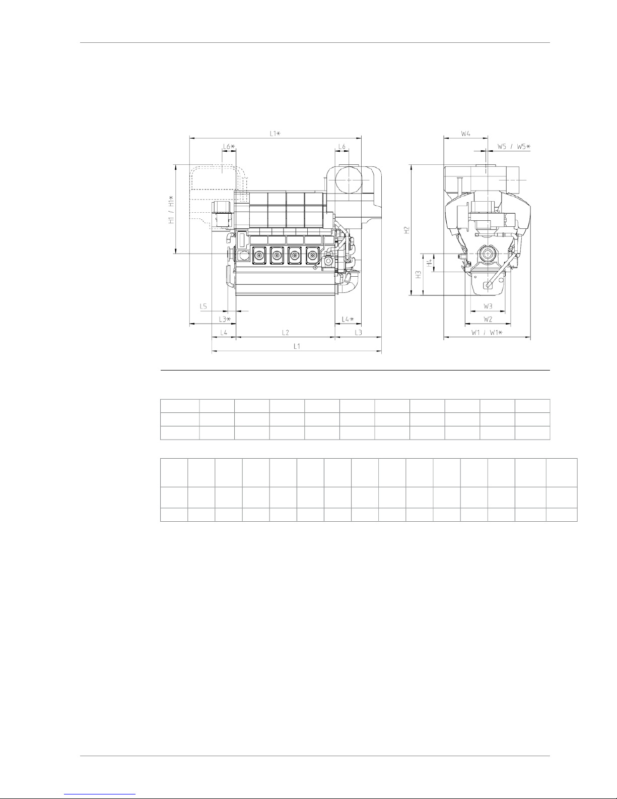
Fig 1-1 W8V31 & W10V31 Main engine dimensions
L6*L6L5L4*L4L3*L3L2L1*L1Engine
50050030098687716501650356061966087W8V31
50050030098687716501650420068366727W10V31
Weight
Liquids
Weight
Engine
**
W5*W5W4W3W2W1*W1H4H3H2H1*H1Engine
3.353.5 /
54.2*
-6767158511531600311531156501496470132053205W8V31
3.9562,2-6767158511531600311531156501496470132053205W10V31
DBAE248994 1-3
1. Main Data and OutputsWärtsilä 31DF Product Guide
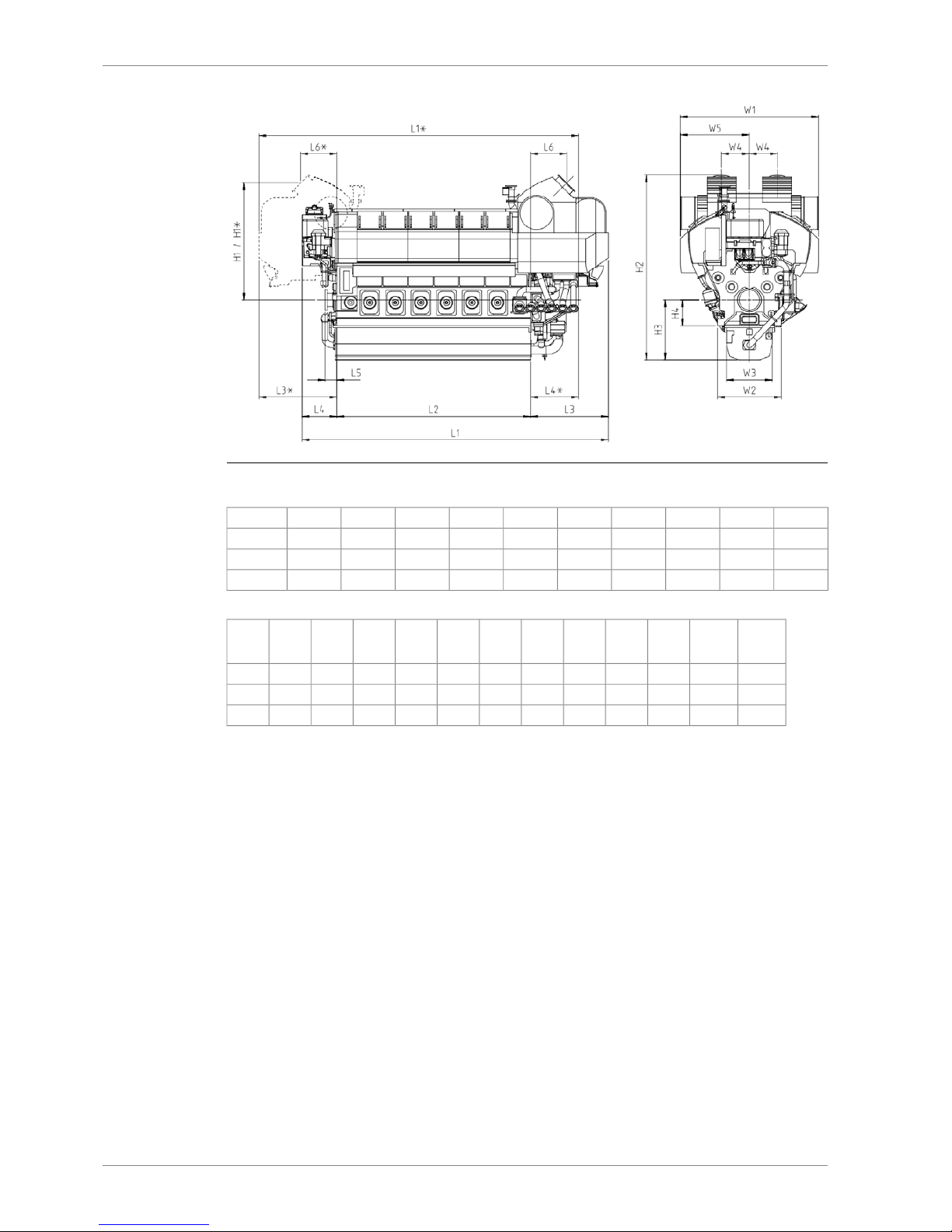
Fig 1-2 W12V31, W14V31 & W16V31 Main engine dimensions
L6*L6L5L4*L4L3*L3L2L1*L1Engine
9089083001250100020002000484080907840W12V31
9089083001250100020002000548087308480W14V31
9089083001250100020002000612093709120W16V31
Weight
Liquids
Weight
Engine
**
W5W4W3W2W1H4H3H2H1*H1Engine
4.9572.817506981153160035006501496463329262926W12V31
5.579.817506981153160035006501496463329262926W14V31
6.2587.917506981153160035006501496463329262926W16V31
1-4 DBAE248994
Wärtsilä 31DF Product Guide1. Main Data and Outputs

Total length of engineL1
Length of the engine blockL2
Length from the engine block to the outer most point in turbocharger endL3
Length from the engine block to the outer most point in non-turbocharger endL4
Length from engine block to crankshaft flangeL5
Length from engine block to center of exhaust gas outletL6
Height from the crankshaft centerline to center of exhaust gas outletH1
Total height of engine (normal wet sump)H2
Height from crankshaft centerline to bottom of the oil sump (normal wet sump)H3
Height from the crankshaft centerline to engine feet (fixed mounted)H4
Total width of engineW1
Width of engine block at the engine feetW2
Width of oil sumpW3
Width from crankshaft centerline to center of exhaust gas outletW4
Width from crankshaft centerline to the outer most point of the engineW5
* Turbocharger at flywheel end;
** Weight without liquids, damper and flywheel (as a rule of thumb, add 60kg per cylinder on
top of 8 and or 10V engine weight or, add 50kg per cylinder for 12, 14 and 16V engines for
additional gas components weight);
All dimensions in mm, weights in tonne.
DBAE248994 1-5
1. Main Data and OutputsWärtsilä 31DF Product Guide

This page intentionally left blank
2. Operating Ranges
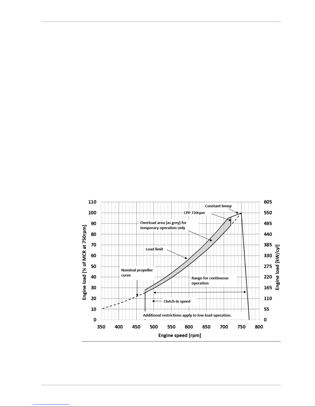
2.1 Engine operating range
Running below nominal speed the load must be limited according to the diagrams in this
chapter in order to maintain engine operating parameters within acceptable limits. Operation
in the shaded area is permitted only temporarily during transients. Minimum speed is indicated
in the diagram, but project specific limitations may apply.
2.1.1 Controllable pitch propellers
An automatic load control system is required to protect the engine from overload. The load
control reduces the propeller pitch automatically, when a pre-programmed load versus speed
curve (“engine limit curve”) is exceeded, overriding the combinator curve if necessary. Engine
load is determined from measured shaft power and actual engine speed. The shaft power
meter is Wärtsilä supply.
The propeller efficiency is highest at design pitch. It is common practice to dimension the
propeller so that the specified ship speed is attained with design pitch, nominal engine speed
and 85% output in the specified loading condition. The power demand from a possible shaft
generator or PTO must be taken into account. The 15% margin is a provision for weather
conditions and fouling of hull and propeller. An additional engine margin can be applied for
most economical operation of the engine, or to have reserve power.
The propulsion control must also include automatic limitation of the load increase rate.
Maximum loading rates can be found later in this chapter.
Fig 2-1 Operating field for CP Propeller (DAAF389037B)
DBAE248994 2-1
2. Operating RangesWärtsilä 31DF Product Guide

NOTE
1) Valid for both gas operation and diesel operation.
2) Minimum engine speed is restricted to 472rpm with engine driven oil pump.
3) Additional restrictions apply to low load operation.
4) Project specific idling and clutch in speed depends on clutch, gearbox and the
Torsional Vibration Calculations.
Remarks: The maximum output may have to be reduced depending on gas properties and
gas pressure. The permissible output will in such case be reduced with same percentage at
all revolution speeds.
2.2 Loading capacity
Controlled load increase is essential for highly supercharged diesel engines, because the
turbocharger needs time to accelerate before it can deliver the required amount of air. A slower
loading ramp than the maximum capability of the engine permits a more even temperature
distribution in engine components during transients.
The engine can be loaded immediately after start, provided that the engine is pre-heated to:
● High Temperature (HT) water temperature is minimum 70°C
● Lubricating oil temperature is minimum 40°C
The ramp for normal loading applies to engines that have reached normal operating
temperature.
2-2 DBAE248994
Wärtsilä 31DF Product Guide2. Operating Ranges
2.2.1 Mechanical propulsion
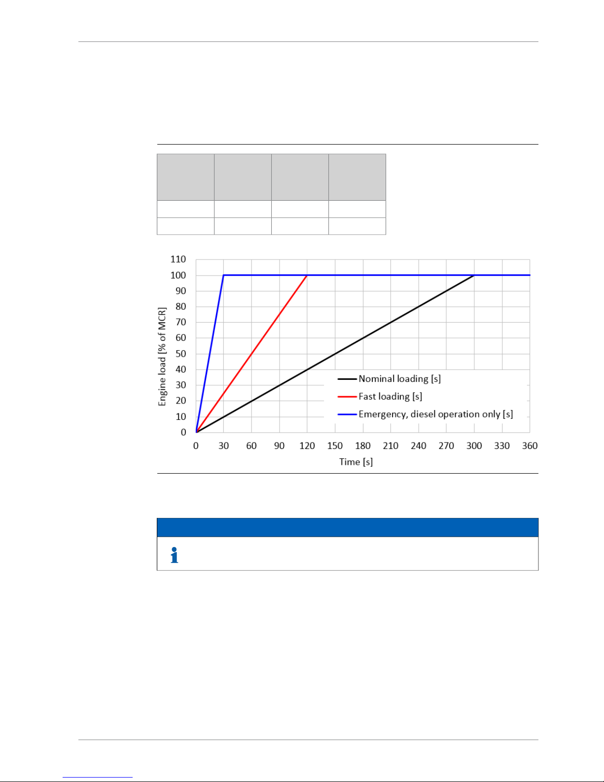
2.2.1.1 Loading Rates Variable speed engines (CPP)
Normal loading rate, variable speed engines, 750 rpm
Table 2-1 Loading rate
Emergency,
diesel operation only
[s]
Fast loading
[s]
Nominal
loading
[s]
Engine load
[% of MCR]
0000
30120300100
Fig 2-2 Normal Loading rate, variable speed engines, 750 rpm
NOTE
If normal loading rate is chosen low load running is limited to normal low load
restriction curve. Please see chapter 2.3.1.
DBAE248994 2-3
2. Operating RangesWärtsilä 31DF Product Guide

Unloading rate, variable speed engines, 750 rpm
Table 2-2 Unloading rate
Emergency,
diesel opera-
tion only
[s]
Fast loading
[s]
Nominal
loading
[s]
Engine load
[% of MCR]
0N/A
0
100
0N/A
60
0
Fig 2-3 Unloading rate, variable speed engines, 750 rpm
The propulsion control must include automatic limitation of the load increase rate. If the control
system has only one load increase ramp, then the ramp for a preheated engine should be
used. In tug applications the engines have usually reached normal operating temperature
before the tug starts assisting. The “emergency” curve is close to the maximum capability of
the engine.
Large load reductions from high load should also be performed gradually. In normal operation
the load should not be reduced from 100% to 0% in less than 15 seconds. When absolutely
necessary, the load can be reduced as fast as the pitch setting system can react (overspeed
due to windmilling must be considered for high speed ships).
2-4 DBAE248994
Wärtsilä 31DF Product Guide2. Operating Ranges
2.2.2 Diesel electric propulsion and auxiliary engines
2.2.2.1 Loading rates Constant speed engines (DE / Aux / CPP)
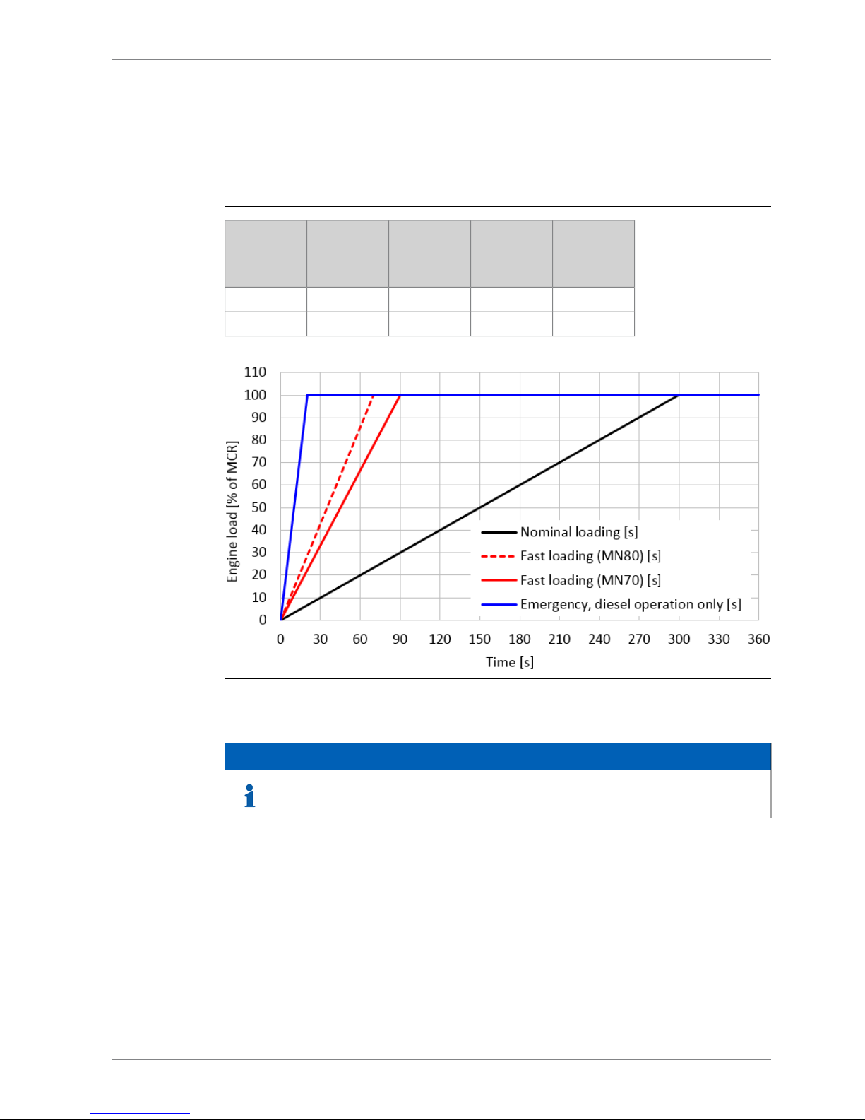
Normal loading rate, constant speed engines, 720/750 rpm (DE / Aux / CPP)
Table 2-3 Normal Loading rate
Emergency,
diesel operation only
[s]
Fast loading
(MN80)
[s]
Fast loading
(MN70)
[s]
Nominal
loading
[s]
Engine load
[% of MCR]
00000
207090300100
Fig 2-4 Normal Loading rate, constant speed engines, 720/750 rpm (DE / Aux / CPP)
NOTE
If normal loading rate is chosen low load running is limited to normal low load
restriction curve. Please see chapter 2.3.1.
DBAE248994 2-5
2. Operating RangesWärtsilä 31DF Product Guide
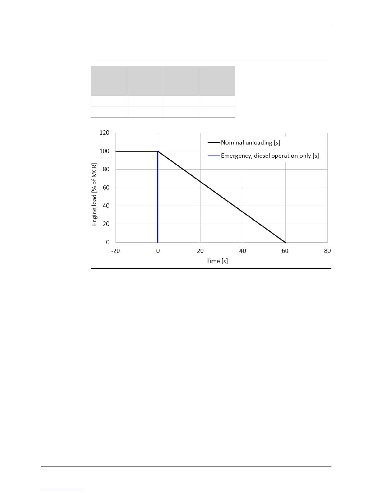
Unloading rate, constant speed engines, 720/750 rpm (DE / Aux / CPP)
Table 2-4 Unloading rate
Emergency,
diesel opera-
tion only
[s]
Fast loading
[s]
Nominal
loading
[s]
Engine load
[% of MCR]
0N/A
0
100
0N/A
60
0
Fig 2-5 Unloading rate, constant speed engines, 720/750 rpm (DE / Aux / CPP)
In diesel electric installations loading ramps are implemented both in the propulsion control
and in the power management system, or in the engine speed control in case isochronous
load sharing is applied. If a ramp without knee-point is used, it should not achieve 100% load
in shorter time than the ramp in the figure. When the load sharing is based on speed droop,
the load increase rate of a recently connected generator is the sum of the load transfer
performed by the power management system and the load increase performed by the
propulsion control.
The “emergency” curve is close to the maximum capability of the engine and it shall not be
used as the normal limit. In dynamic positioning applications loading ramps corresponding to
20-30 seconds from zero to full load are however normal. If the vessel has also other operating
modes, a slower loading ramp is recommended for these operating modes.
In typical auxiliary engine applications there is usually no single consumer being decisive for
the loading rate. It is recommended to group electrical equipment so that the load is increased
in small increments, and the resulting loading rate roughly corresponds to the “normal” curve.
In normal operation the load should not be reduced from 100% to 0% in less than 15 seconds.
If the application requires frequent unloading at a significantly faster rate, special arrangements
can be necessary on the engine. In an emergency situation the full load can be thrown off
instantly.
2-6 DBAE248994
Wärtsilä 31DF Product Guide2. Operating Ranges
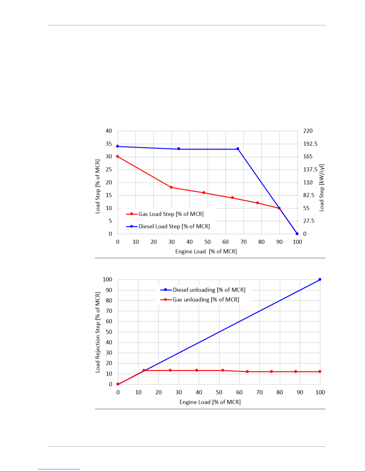
2.2.2.2 Instant Load Application
The maximum permissible load step which may be applied at any given load can be read from
the figure below. The values are valid for engines operating in island mode (speed control).
Furthermore the stated values are limited to a running engine that has reached nominal
operating temperatures, or for an engine which has been operated at above 30% load within
the last 30 minutes.
Cyclic (wave) load-taking capability can be evaluated from the figures below:
● Max instant load step = cyclic load amplitude
○ Example: With cyclic loading at average load 57% the load variation amplitude can be
14%, i.e ±7% (=50% + 14%/2)
Fig 2-6 Load Steps, CS 750 rpm
Fig 2-7 Unloading Steps, CS 750 rpm
DBAE248994 2-7
2. Operating RangesWärtsilä 31DF Product Guide

2.3 Low load operation
2.3.1 Normal Low load operation - Normal load acceptance
In order to avoid fouling of the engine, recommended limits to the low load operation are given.
Low load operation is all loads below 20% load. Cumulative low load operation should not
exceed the recommended values given in the chart and table. The time is reset after a cleaning
run at minimum 70% load for a minimum of 1 hour.
Black line (diesel mode) limit is valid in diesel mode when intention is to continue in diesel
mode. In case the intention is to transfer to gas mode and continue operating in gas mode
then blue line (gas mode limit) is valid also for diesel mode.
The loading rates according to Normal low load load operations, chapter load performance
are allowed with these low load operation limits.
If recommended time limits are exceeded then engine shall not be loaded faster than the
nominal loading curve in the chapter loading performance.
Absolute idling time 10 minutes if the engine is to be stopped, 5 hours in gas mode or 10 hours
in diesel mode if engine is loaded afterwards.
2-8 DBAE248994
Wärtsilä 31DF Product Guide2. Operating Ranges
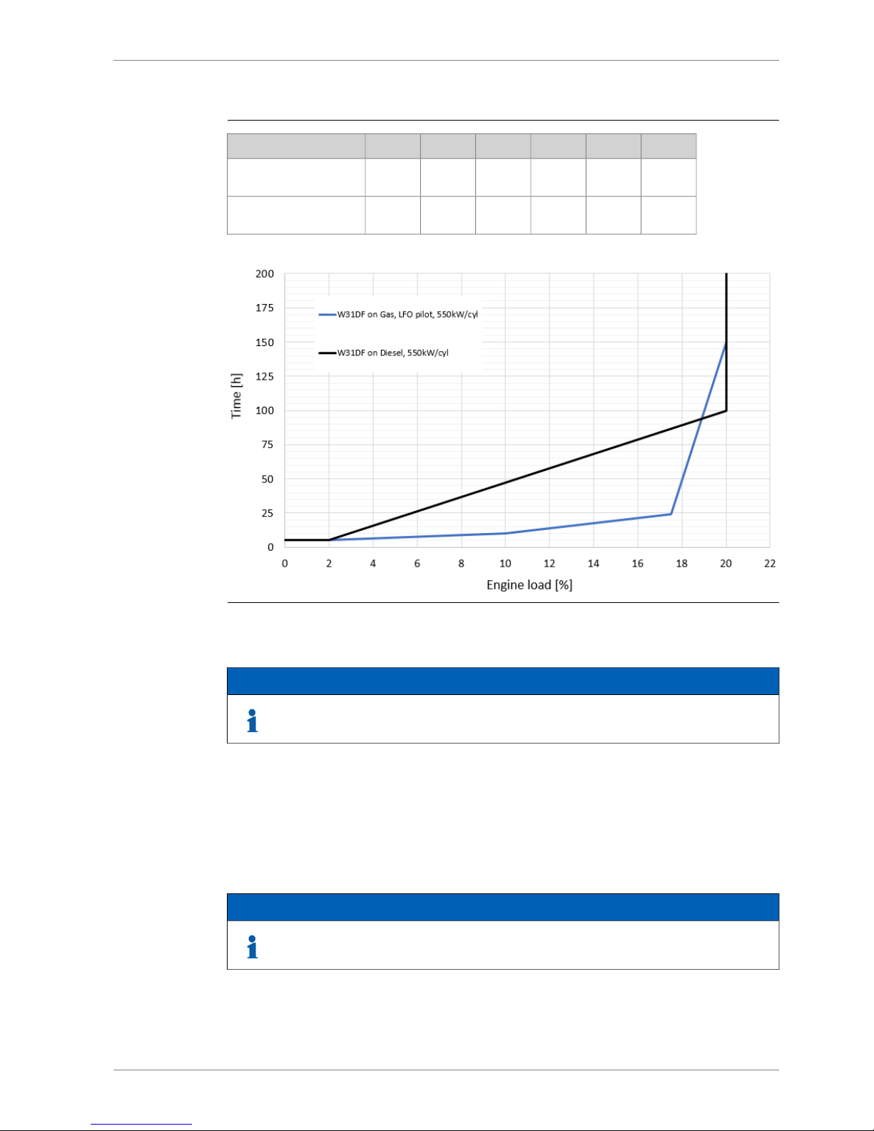
Table 2-5 Max continous low load operation time for load acceptance according to
Normal Load acceptance chapter
2017.510
20%
Load
150
241055h
W31DF on Gas, LFO pilot, 550kW/cyl
100
874755h
W31DF on Diesel,
550kW/cyl
Fig 2-8 Low load operating restrictions
NOTE
Black line is intended for diesel mode operation and blue line is intended for gas
mode operation.
2.3.2 Absolute idling
Absolute idling (declutched main engine, disconnected generator)
- Maximum 10 minutes if the engine is to be stopped after the idling. 3-5 minutes idling before
stop is recommended.
- Maximum 5 hours in gas mode and 10 hours in diesel mode if the engine is to be loaded
after the idling.
NOTE
Operating restrictions on SCR applications in low load operation to be observed.
DBAE248994 2-9
2. Operating RangesWärtsilä 31DF Product Guide
2.4 Low air temperature
In standard conditions the following minimum inlet air temperatures apply:
Gas mode:
● Low load + 5ºC
● High load -10ºC
Diesel mode:
● Starting + 5ºC
● Idling - 5ºC
● High load - 10ºC
For further guidelines, see chapter Combustion air system design.
NOTE
Air Waste Gate (AWG) is needed when suction air temperature is below +5°C.
2-10 DBAE248994
Wärtsilä 31DF Product Guide2. Operating Ranges
3. Technical Data
3.1 Introduction
This chapter contains technical data of the engine (heat balance, flows, pressures etc.) for
design of auxiliary systems. Further design criteria for external equipment and system layouts
are presented in the respective chapter.
3.1.1 Engine driven pumps
The fuel consumption stated in the technical data tables is with engine driven pumps. The
increase in fuel consumption with engine driven pumps is given in the table below; correction
in g/kWh (Diesel mode) and or kJ/kWh (Gas mode).
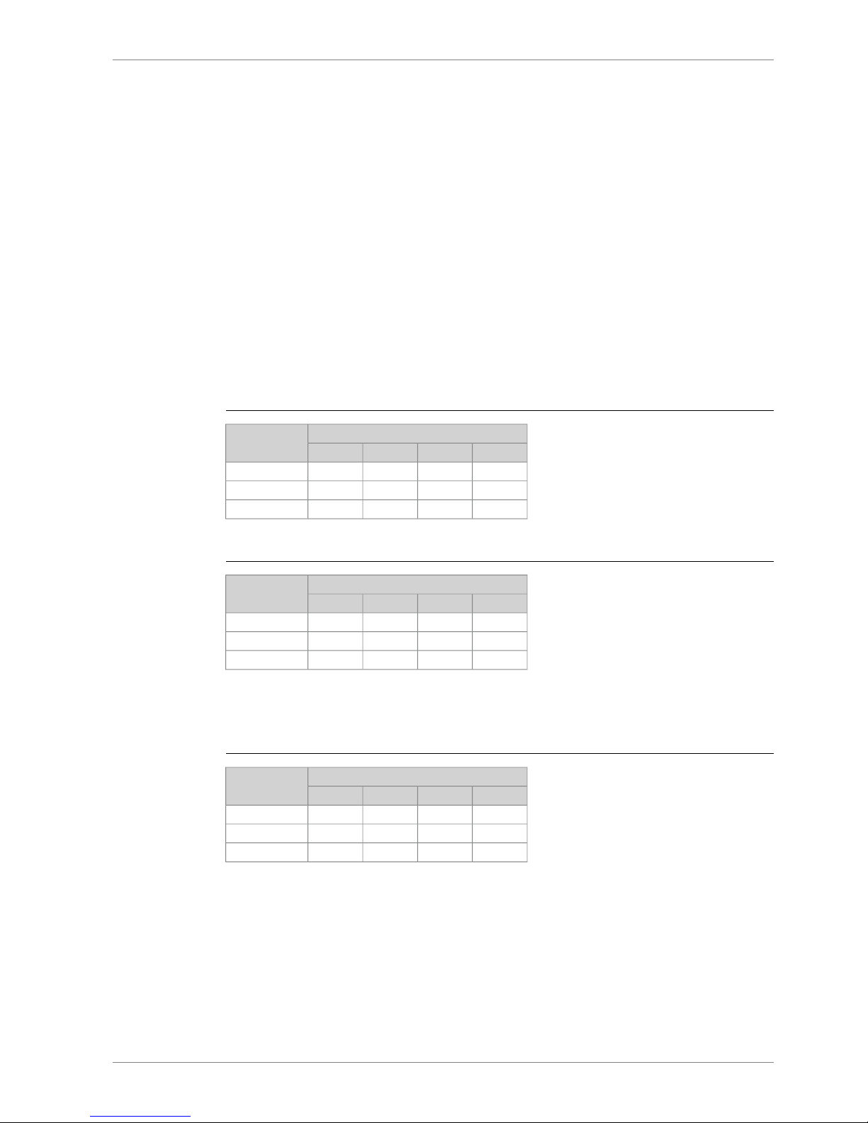
3.1.1.1 Diesel mode
Table 3-1 Constant speed engines (DE, CPP, Aux), 750/720rpm, MDF/HFO
Engine load [%]Engine driven
pumps
507585100
-2.6-1.6-1.4-1.2Lube oil
-1.0-0.7-0.6-0.5LT Water
-1.0-0.7-0.6-0.5HT Water
Table 3-2 Variable speed engines (CPP), 750rpm, MDF/HFO
Engine load [%]Engine driven
pumps
507585100
-1.4-1.4-1.3-1.4Lube oil
-0.5-0.5-0.5-0.5LT Water
-0.5-0.5-0.5-0.5HT Water
3.1.1.2 Gas mode
Table 3-3 Constant speed engines (DE, CPP, Aux), 750/720rpm, MDF/HFO
Engine load [%]Engine driven
pumps
507585100
-108.6-68.6-60.0-50.5Lube oil
-44.8-27.6-24.8-21.0LT Water
-44.8-27.6-24.8-21.0HT Water
DBAE248994 3-1
3. Technical DataWärtsilä 31DF Product Guide

Table 3-4 Variable speed engines (CPP), 750rpm, MDF/HFO
Engine load [%]Engine driven
pumps
507585100
-58.1-57.1-57.1-57.1Lube oil
-21.0-21.0-21.0-21.0LT Water
-21.0-21.0-21.0-21.0HT Water
3-2 DBAE248994
Wärtsilä 31DF Product Guide3. Technical Data

3.2 Wärtsilä 8V31DF
MEAUXAUXDEDE
Wärtsilä 8V31DF
Diesel
mode
Gas
mode
Diesel
mode
Gas
mode
Diesel
mode
Gas
mode
Diesel
mode
Gas
mode
Diesel
mode
Gas
mode
750750720750720rpmEngine speed
550550530550530kWCylinder output
VariableConstantConstantConstantConstantSpeed mode
44004400424044004240kWEngine output
2.712.712.722.712.72MPaMean effective pressure
Tier 2Tier 3Tier 2Tier 3Tier 2Tier 3Tier 2Tier 3Tier 2Tier 3IMO compliance
Combustion air system (Note 1)
8.46.68.46.68.16.48.46.68.16.4kg/sFlow at 100% load
4545454545°CTemperature at turbocharger in-
take, max.
60606060606060606060°CTemperature after air cooler (TE
601)
Exhaust gas system (Note 2)
8.77.48.77.48.17.18.77.48.17.1kg/sFlow at 100% load
7.46.17.46.16.95.97.46.16.95.9kg/sFlow at 85% load
6.65.56.95.46.45.26.95.46.45.2kg/sFlow at 75% load
5.03.84.93.84.63.74.93.84.63.7kg/sFlow at 50% load
270300270300270300270300270300°CTemperature after turbocharger
at 100% load (TE 517)
260320270350270350270350270350°CTemperature after turbocharger
at 85% load (TE 517)
270310260350260350260350260350°CTemperature after turbocharger
at 75% load (TE 517)
270330280370280370280370280370°CTemperature after turbocharger
at 50% load (TE 517)
77777kPaBackpressure, max.
697657697657671647697657671647mmCalculated exhaust diameter for
35 m/s
Heat balance at 100% load (Note 3)
424360424360408344424360408344kWJacket water, HT-circuit
768504768504680472768504680472kWCharge air, HT-circuit
1296106413041072120810241304107212081024kWCharge air, LT-circuit
488408488408472392488408472392kWLubricating oil, LT-circuit
120120120120120120120120120120kWRadiation
Fuel consumption (Note 4)
(Note 5)
-7280-7280-7250-7280-7250kJ/kWhTotal energy consumption at
100% load
-7230-7350-7300-7350-7300kJ/kWhTotal energy consumption at 85%
load
-7250-7500-7430-7500-7430kJ/kWhTotal energy consumption at 75%
load
-7330-7820-7790-7820-7790kJ/kWhTotal energy consumption at 50%
load
-7128-7128-7097-7128-7097kJ/kWhFuel gas consumption at 100%
load
DBAE248994 3-3
3. Technical DataWärtsilä 31DF Product Guide

MEAUXAUXDEDE
Wärtsilä 8V31DF
Diesel
mode
Gas
mode
Diesel
mode
Gas
mode
Diesel
mode
Gas
mode
Diesel
mode
Gas
mode
Diesel
mode
Gas
mode
750750720750720rpmEngine speed
550550530550530kWCylinder output
VariableConstantConstantConstantConstantSpeed mode
-7059-7171-7121-7171-7121kJ/kWhFuel gas consumption at 85%
load
-7082-7294-7226-7294-7226kJ/kWhFuel gas consumption at 75%
load
-7157-7515-7484-7515-7484kJ/kWhFuel gas consumption at 50%
load
177.23.8177.23.8176.33.8177.23.8176.33.8g/kWhFuel oil consumption at 100%
load
172.54.2174.44.5173.14.4174.44.5173.14.4g/kWhFuel oil consumption at85% load
176.34.1177.05.1176.85.0177.05.1176.85.0g/kWhFuel oil consumption at75% load
180.44.3185.07.6184.37.6185.07.6184.37.6g/kWhFuel oil consumption 50% load
Fuel gas system
-895-895-895-895-895kPa (a)Gas pressure at engine inlet, min
(PT901)
-1015-1015-1015-1015-1015kPa (a)Gas pressure to Gas Valve Unit,
min
-0...60-0...60-0...60-0...60-0...60°CGas temperature beforeGas Valve
Unit
Fuel oil system
1000±1001000±1001000±1001000±1001000±100kPaPressure before HP pumps (PT
101)
3.63.63.63.63.6m3/hEngine driven pump capacity
(MDF only)
16...24-16...24-16...24-16...24-16...24-cStHFO viscosity before the engine
140-140-140-140-140-°CMax. HFO temperature before
engine (TE 101)
2.02.02.02.02.0cStMDF viscosity, min.
4545454545°CMax. MDF temperature before
engine (TE 101)
0.50.50.50.50.5kg/hLeak fuel quantity (HFO), clean
fuel at 100% load
1.50.91.50.91.50.91.50.91.50.9kg/hLeak fuel quantity (MDF), clean
fuel at 100% load
Lubricating oil system
420420420420420kPaPressure before bearings, nom.
(PT 201)
4040404040kPaSuction ability, including pipe
loss, max.
150150150150150kPaPriming pressure, nom. (PT 201)
3535353535kPaSuction ability priming pump, in-
cluding pipe loss, max.
7070707070°CTemperature before bearings,
nom. (TE 201)
8282828282°CTemperature after engine, approx.
144130125130125m3/hPump capacity (main), engine
driven
100100100100100m3/hPump capacity (main), electrically
driven
40.0 / 40.040.0 / 40.040.0 / 40.040.0 / 40.040.0 / 40.0m3/hPriming pump capacity (50/60Hz)
3-4 DBAE248994
Wärtsilä 31DF Product Guide3. Technical Data

MEAUXAUXDEDE
Wärtsilä 8V31DF
Diesel
mode
Gas
mode
Diesel
mode
Gas
mode
Diesel
mode
Gas
mode
Diesel
mode
Gas
mode
Diesel
mode
Gas
mode
750750720750720rpmEngine speed
550550530550530kWCylinder output
VariableConstantConstantConstantConstantSpeed mode
2.82.82.82.82.8
m
3
Oil volume, wet sump, nom.
55555m
3
Oil volume in separate system oil
tank
0.450.350.450.350.450.350.450.350.450.35g/kWhOil consumption at 100% load,
approx.
19601960196019601960l/minCrankcase ventilation flow rate at
full load
0.10.10.10.10.1kPaCrankcase ventilation backpres-
sure, max.
6.0...6.86.0...6.86.0...6.86.0...6.86.0...6.8lOil volume in turning device
Cooling water system
HT cooling water system
358 + static358 + static358 + static358 + static358 + statickPaPressure at engine, after pump,
nom. (PT 401)
600600600600600kPaPressure at engine, after pump,
max. (PT 401)
8383838383°CTemperature before cylinders,
approx. (TE 401)
9696969696°CTemperature after engine, nom.
8080808080m3/hCapacity of engine driven pump,
nom.
210210210210210kPaPressure drop over engine, total
100100100100100
kPaPressure drop in external system,
max.
70...15070...15070...15070...15070...150kPaPressure from expansion tank
0.350.350.350.350.35m
3
Water volume in engine
365365365365365kPaDelivery head of stand-by pump
LT cooling water system
650+ static650+ static650+ static650+ static650+ statickPaPressure at engine, after pump,
nom. (PT 451)
40/ 4540/ 4540/ 4540/ 4540/ 45°CTemperature before engine, nom
(TE 451)
8080808080m3/hCapacity of engine driven pump,
nom.
110110110110110kPaPressure drop over charge air
cooler (two-stage)
100100100100100
kPaPressure drop in external system,
max.
70...15070...15070...15070...15070...150kPaPressure from expansion tank
Starting air system
30003000300030003000kPaPressure, nom.
15001500150015001500kPaPressure at engine during start,
min. (alarm) (20°C)
30003000300030003000kPaPressure, max.
15001500150015001500kPaLow pressure limit in air vessels
5.95.95.95.95.9Nm
3
Starting air consumption, start
(successful)
DBAE248994 3-5
3. Technical DataWärtsilä 31DF Product Guide

Notes:
At ISO 15550 conditions (ambient air temperature 25°C, LT-water 25°C) and 100% load. Flow tolerance 9%.Note 1
At ISO 15550 conditions (ambient air temperature 25°C, LT-water 25°C) and 100% load. Flow tolerance 9% and temperature tolerance 10°C in gasmodeoperation. Flow tolerance 9%andtemperaturetolerance 15°C in dieselmode operation.
Note 2
At 100% output and nominal speed. The figures are valid for ambient conditions according to ISO 15550 except for LTwater temperature, which is corresponding to charge air receiver temperature 55ºC in gas operation and 60 ºC in diesel
mode. With engine driven water and lubricating oil pumps. Tolerance for cooling water heat 10%, tolerance for radiation
heat 20%. Fouling factors and a margin to be taken into account when dimensioning heat exchangers. In arctic option
all charge air coolers are in LT circuit.
Note 3
Validity of the data in diesel mode operation: at ambient conditions according to ISO 15550. Lower calorific value 42700
kJ/kg. With engine driven pumps (two cooling water + one lubricating oil pump). Tolerance 5%.
Note 4
Validity of the data in gas fuel operation: total barometric pressure, air temperature and relative humidity according to
ISO 15550:2002(E), LT water temperature corresponding to receiver temperature 55°C, pilot fuel cetane index minimum
50 according to ISO 4264. Lower calorific value 42 700 kJ/kg for pilot fuel and 49 700 kJ/kg for gas fuel. With engine
driven pumps (two cooling water pumps, one lubricating oil pump). Tolerance 5%.
Note 5
ME = Engine driving propeller, variable speed
AE = Auxiliary engine driving generator
DE = Diesel-Electric engine driving generator
Subject to revision without notice.
3-6 DBAE248994
Wärtsilä 31DF Product Guide3. Technical Data
 Loading...