

WÄRTSILÄ 46F Series, 6L46F, 12V46F, 14V46F, 16V46F Product Manual
...
PRODUCT GUIDE
Wärtsilä 46F

© Copyright by WÄRTSILÄ FINLAND Oy
All rights reserved. No part of this booklet may be reproduced or copied in any form or by any means (electronic,
mechanical, graphic, photocopying, recording, taping or other information retrieval systems) without the prior written
permission of the copyright owner.
THIS PUBLICATION IS DESIGNED TO PROVIDE AN ACCURATE AND AUTHORITATIVE INFORMATION WITH
REGARD TO THE SUBJECT-MATTER COVERED AS WAS AVAILABLE AT THE TIME OF PRINTING. HOWEVER,THE
PUBLICATION DEALS WITH COMPLICATED TECHNICAL MATTERS SUITED ONLY FOR SPECIALISTS IN THE
AREA, AND THE DESIGN OF THE SUBJECT-PRODUCTS IS SUBJECT TO REGULAR IMPROVEMENTS,
MODIFICATIONS AND CHANGES. CONSEQUENTLY, THE PUBLISHER AND COPYRIGHT OWNER OF THIS
PUBLICATION CAN NOT ACCEPT ANY RESPONSIBILITY OR LIABILITY FOR ANY EVENTUAL ERRORS OR
OMISSIONS IN THIS BOOKLET OR FOR DISCREPANCIES ARISING FROM THE FEATURES OF ANY ACTUAL ITEM
IN THE RESPECTIVE PRODUCT BEING DIFFERENT FROM THOSE SHOWN IN THIS PUBLICATION. THE PUBLISHER
AND COPYRIGHT OWNER SHALL UNDER NO CIRCUMSTANCES BE HELD LIABLE FOR ANY FINANCIAL
CONSEQUENTIAL DAMAGES OR OTHER LOSS, OR ANY OTHER DAMAGE OR INJURY, SUFFERED BY ANY
PARTY MAKING USE OF THIS PUBLICATION OR THE INFORMATION CONTAINED HEREIN.

Introduction
This Product Guide provides data and system proposals for the early design phase of marine
engine installations. For contracted projects specific instructions for planning the installation
are always delivered. Any data and information herein is subject to revision without notice.
This 3/2017 issue replaces all previous issues of the Wärtsilä 46F Product Guides.
UpdatesPublishedIssue
Technical data updated07.11.20173/2017
Technical data updated27.06.20172/2017
Technical data updated10.02.20171/2017
Flow diagrams updated, other minor updates27.06.20161/2016
Several updates throughout the product guide27.08.20131/2013
Wärtsilä, Marine Solutions
Italy, November 2017
Wärtsilä 46F Product Guide - a19 - 1 December 2017 iii
IntroductionWärtsilä 46F Product Guide

Table of contents
1-11. Main Data and Outputs .......................................................................................................................
1-11.1 Maximum continuous output .......................................................................................................
1-21.2 Reference conditions ...................................................................................................................
1-21.3 Operation in inclined position .....................................................................................................
1-31.4 Dimensions and weights .............................................................................................................
2-12. Operating Ranges ................................................................................................................................
2-12.1 Engine operating range ...............................................................................................................
2-22.2 Loading capacity .........................................................................................................................
2-32.3 Operation at low load and idling ..................................................................................................
2-42.4 Low air temperature ....................................................................................................................
3-13. Technical Data ......................................................................................................................................
3-13.1 Introduction ..................................................................................................................................
3-23.2 Wärtsilä 6L46F .............................................................................................................................
3-53.3 Wärtsilä 7L46F .............................................................................................................................
3-83.4 Wärtsilä 8L46F .............................................................................................................................
3-113.5 Wärtsilä 9L46F .............................................................................................................................
3-143.6 Wärtsilä 12V46F ...........................................................................................................................
3-173.7 Wärtsilä 14V46F ...........................................................................................................................
3-203.8 Wärtsilä 16V46F ...........................................................................................................................
4-14. Description of the Engine ....................................................................................................................
4-14.1 Definitions ....................................................................................................................................
4-14.2 Main components and systems ..................................................................................................
4-54.3 Cross section of the engine .........................................................................................................
4-74.4 Overhaul intervals and expected life times ..................................................................................
4-74.5 Engine storage .............................................................................................................................
5-15. Piping Design, Treatment and Installation .........................................................................................
5-15.1 Pipe dimensions ..........................................................................................................................
5-25.2 Trace heating ...............................................................................................................................
5-25.3 Operating and design pressure ...................................................................................................
5-35.4 Pipe class ....................................................................................................................................
5-45.5 Insulation .....................................................................................................................................
5-45.6 Local gauges ...............................................................................................................................
5-45.7 Cleaning procedures ...................................................................................................................
5-55.8 Flexible pipe connections ............................................................................................................
5-65.9 Clamping of pipes ........................................................................................................................
6-16. Fuel Oil System ....................................................................................................................................
6-16.1 Acceptable fuel characteristics ...................................................................................................
6-56.2 Internal fuel oil system .................................................................................................................
6-76.3 External fuel oil system ................................................................................................................
7-17. Lubricating Oil System ........................................................................................................................
7-17.1 Lubricating oil requirements ........................................................................................................
7-27.2 Internal lubricating oil system ......................................................................................................
7-57.3 External lubricating oil system .....................................................................................................
7-147.4 Crankcase ventilation system .....................................................................................................
7-157.5 Flushing instructions ....................................................................................................................
iv Wärtsilä 46F Product Guide - a19 - 1 December 2017
Wärtsilä 46F Product GuideTable of contents

8-18. Compressed Air System ......................................................................................................................
8-18.1 Instrument air quality ...................................................................................................................
8-18.2 Internal compressed air system ..................................................................................................
8-48.3 External compressed air system .................................................................................................
9-19. Cooling Water System .........................................................................................................................
9-19.1 Water quality ...............................................................................................................................
9-29.2 Internal cooling water system ......................................................................................................
9-79.3 External cooling water system ....................................................................................................
10-110. Combustion Air System .......................................................................................................................
10-110.1 Engine room ventilation ...............................................................................................................
10-310.2 Combustion air system design ....................................................................................................
11-111. Exhaust Gas System ............................................................................................................................
11-111.1 Internal exhaust gas system ........................................................................................................
11-311.2 Exhaust gas outlet .......................................................................................................................
11-511.3 External exhaust gas system .......................................................................................................
12-112. Turbocharger Cleaning ........................................................................................................................
12-112.1 Turbocharger cleaning system ....................................................................................................
12-212.2 Wärtsilä control unit for four engines, UNIC C2 & C3 ................................................................
13-113. Exhaust Emissions ...............................................................................................................................
13-113.1 Diesel engine exhaust components ............................................................................................
13-213.2 Marine exhaust emissions legislation ..........................................................................................
13-313.3 Methods to reduce exhaust emissions ........................................................................................
14-114. Automation System .............................................................................................................................
14-114.1 UNIC C2 .......................................................................................................................................
14-614.2 Functions ....................................................................................................................................
14-814.3 Alarm and monitoring signals ......................................................................................................
14-814.4 Electrical consumers ...................................................................................................................
14-1014.5 System requirements and guidelines for diesel-electric propulsion ............................................
15-115. Foundation ............................................................................................................................................
15-115.1 Steel structure design ..................................................................................................................
15-115.2 Engine mounting ..........................................................................................................................
16-116. Vibration and Noise ..............................................................................................................................
16-116.1 External forces and couples ........................................................................................................
16-316.2 Torque variations .........................................................................................................................
16-316.3 Mass moments of inertia .............................................................................................................
16-416.4 Structure borne noise ..................................................................................................................
16-516.5 Air borne noise .............................................................................................................................
16-616.6 Exhaust noise ..............................................................................................................................
17-117. Power Transmission ............................................................................................................................
17-117.1 Flexible coupling ..........................................................................................................................
17-117.2 Clutch ..........................................................................................................................................
17-117.3 Shaft locking device ....................................................................................................................
17-117.4 Power-take-off from the free end ................................................................................................
17-317.5 Input data for torsional vibration calculations .............................................................................
17-417.6 Turning gear .................................................................................................................................
18-118. Engine Room Layout ...........................................................................................................................
18-118.1 Crankshaft distances ...................................................................................................................
18-718.2 Space requirements for maintenance .........................................................................................
Wärtsilä 46F Product Guide - a19 - 1 December 2017 v
Table of contentsWärtsilä 46F Product Guide

18-718.3 Transportation and storage of spare parts and tools ..................................................................
18-718.4 Required deck area for service work ...........................................................................................
19-119. Transport Dimensions and Weights ...................................................................................................
19-119.1 Lifting the in-line engine ..............................................................................................................
19-319.2 Lifting the V-engine ......................................................................................................................
19-419.3 Engine components .....................................................................................................................
20-120. Product Guide Attachments ...............................................................................................................
21-121. ANNEX ...................................................................................................................................................
21-121.1 Unit conversion tables .................................................................................................................
21-221.2 Collection of drawing symbols used in drawings ........................................................................
vi Wärtsilä 46F Product Guide - a19 - 1 December 2017
Wärtsilä 46F Product GuideTable of contents
1. Main Data and Outputs
The Wärtsilä 46F is a 4-stroke, non-reversible, turbocharged and intercooled diesel engine
with direct fuel injection (twin pump).
460 mmCylinder bore
580 mmStroke
96.4 l/cylPiston displacement
2 inlet valves and 2 exhaust valvesNumber of valves
6, 7, 8 and 9 in-line; 12, 14 and 16 in V-formCylinder configuration
clockwise, counter-clockwise on requestDirection of rotation
600 rpmSpeed
11.6 m/sMean piston speed
1.1 Maximum continuous output
Table 1-1 Maximum continuos output
IMO Tier 2Cylinder configuration
bhpkW
97907200W 6L46F
114208400W 7L46F
130509600W 8L46F
1468010800W 9L46F
1958014400W 12V46F
2284016800W 14V46F
2611019200W 16V46F
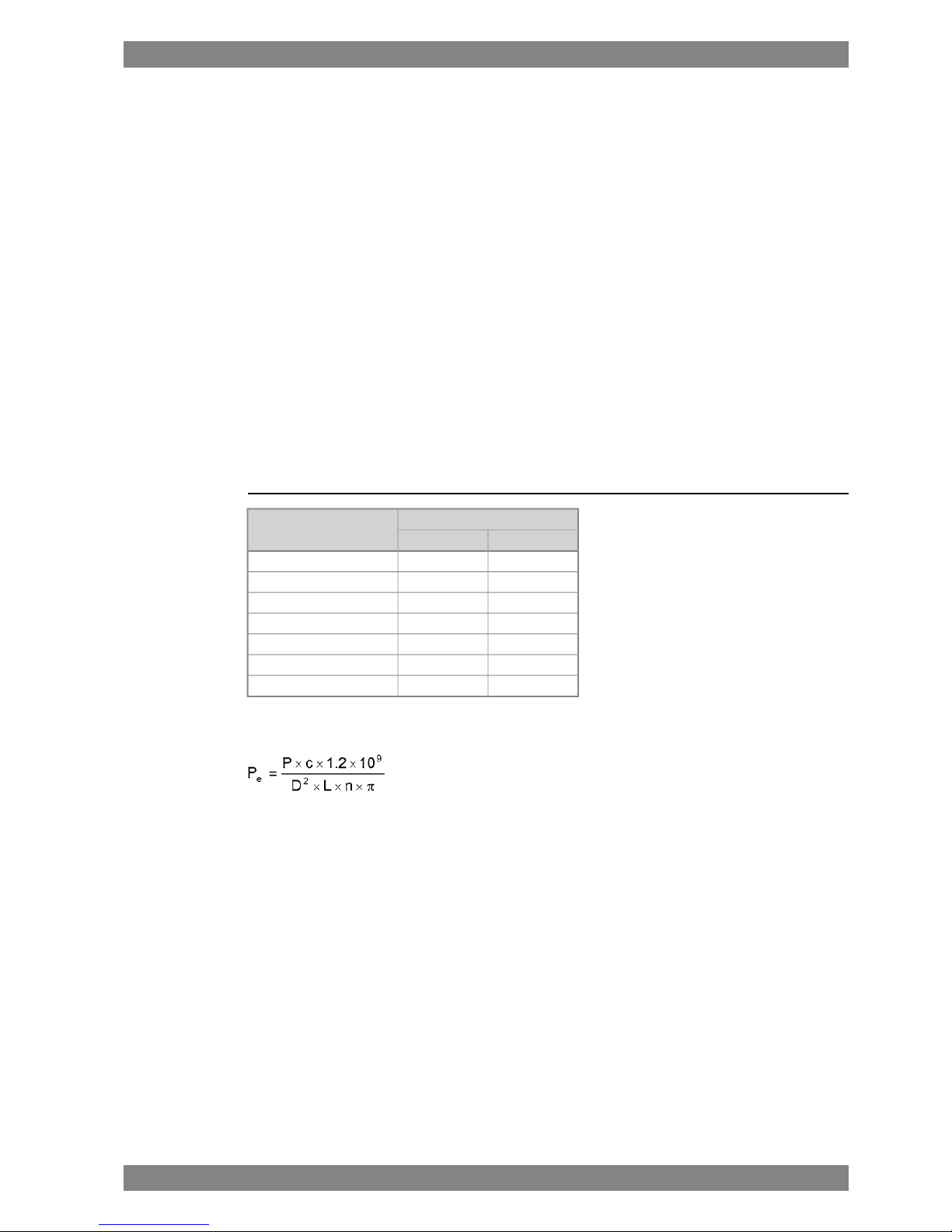
The mean effective pressure Pecan be calculated using the following formula:
where:
mean effective pressure [bar]Pe=
output per cylinder [kW]P =
engine speed [r/min]n =
cylinder diameter [mm]D =
length of piston stroke [mm]L =
operating cycle (4)c =
Wärtsilä 46F Product Guide - a19 - 1 December 2017 1-1
1. Main Data and OutputsWärtsilä 46F Product Guide

1.2 Reference conditions
The output is available up to an air temperature of max. 45°C. For higher temperatures, the
output has to be reduced according to the formula stated in ISO 3046-1:2002 (E).
The specific fuel oil consumption is stated in the chapter Technical data. The stated specific
fuel oil consumption applies to engines with engine driven pumps, operating in ambient
conditions according to ISO 15550:2002 (E). The ISO standard reference conditions are:
100 kPatotal barometric pressure
25°Cair temperature
30%relative humidity
25°Ccharge air coolant temperature
Correction factors for the fuel oil consumption in other ambient conditions are given in standard
ISO 15550:2002 (E).
1.3 Operation in inclined position
Max. inclination angles at which the engine will operate satisfactorily.
15°
● Permanent athwart ship inclinations
22.5°
● Temporary athwart ship inclinations
10°
● Permanent fore-and-aft inclinations
1-2 Wärtsilä 46F Product Guide - a19 - 1 December 2017
Wärtsilä 46F Product Guide1. Main Data and Outputs
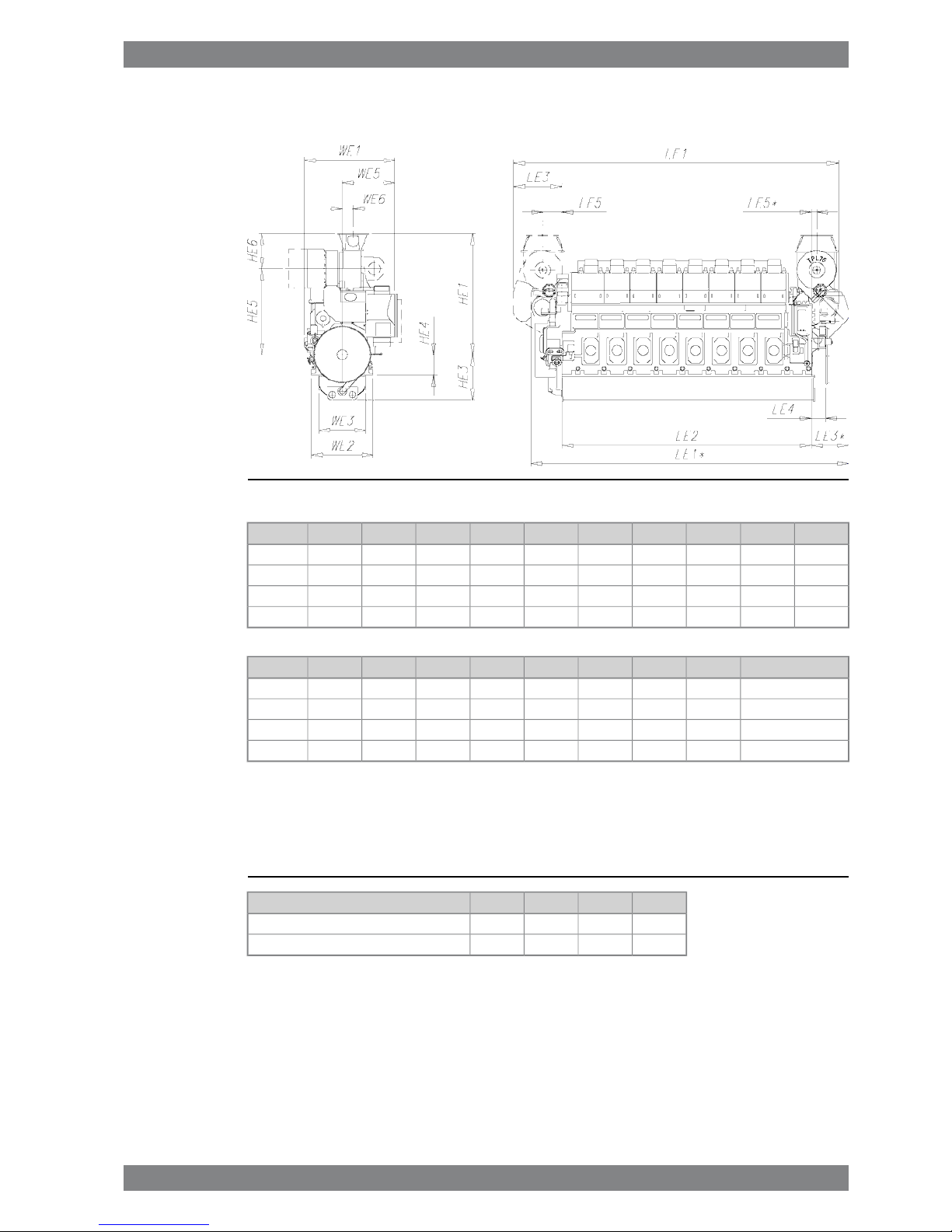
1.4 Dimensions and weights
Fig 1-1 In-line engines (DAAE012051c)
HE3HE1LE5LE5*LE4LE3LE3*LE2LE1LE1*Engine
14303500690180460155013206170862084706L46F
14303800800180460155014656990944094357L46F
1430380080018046015501465781010260102558L46F
1430380080018046015501465863011080110759L46F
Weight [ton]WE6WE5WE3WE2WE1HE6HE5HE4Engine
97385153514801940290579027106506L46F
1133401760148019403130110027006507L46F
1243401760148019403130110027006508L46F
1403401760148019403130110027006509L46F
* Turbocharger at flywheel end
All dimensions in mm. The weights are dry weights of rigidly mounted engines without flywheel.
Table 1-2 Additional weights [ton]:
9L46F8L46F7L46F6L46FItem
1...21...21...21...2Flywheel
3333Flexible mounting (without limiters)
Wärtsilä 46F Product Guide - a19 - 1 December 2017 1-3
1. Main Data and OutputsWärtsilä 46F Product Guide
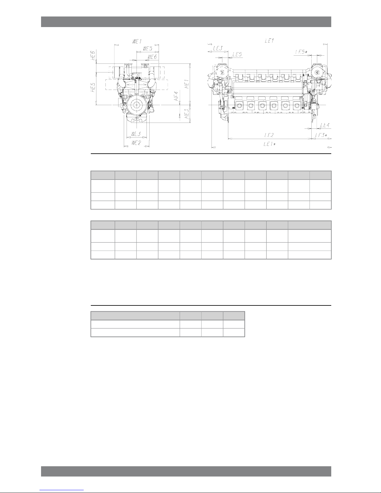
Fig 1-2 V-engines (DAAE075826B)
HE3HE1LE5LE5*LE4LE3LE3*LE2LE1LE1*Engine
16203765* /
3770
7745204601952183076001028410945
12V46F
16204234872-4852347-865011728-14V46F
16204234872-4852347-970012871-16V46F
Weight [ton]WE6WE5WE3WE2WE1HE6HE5HE4Engine
1777602825* /
3150
182022904040* /
4026
7902975* /
2980
800
12V46F
21689231501820229046781100313480014V46F
23389231501820229046781100313480016V46F
* Turbocharger in flywheel end
All dimensions in mm. The weights are dry weights of rigidly mounted engines without flywheel.
Table 1-3 Additional weights [ton]:
16V46F14V46F12V46FItem
1...21...21...2Flywheel
333Flexible mounting (without limiters)
1-4 Wärtsilä 46F Product Guide - a19 - 1 December 2017
Wärtsilä 46F Product Guide1. Main Data and Outputs
2. Operating Ranges
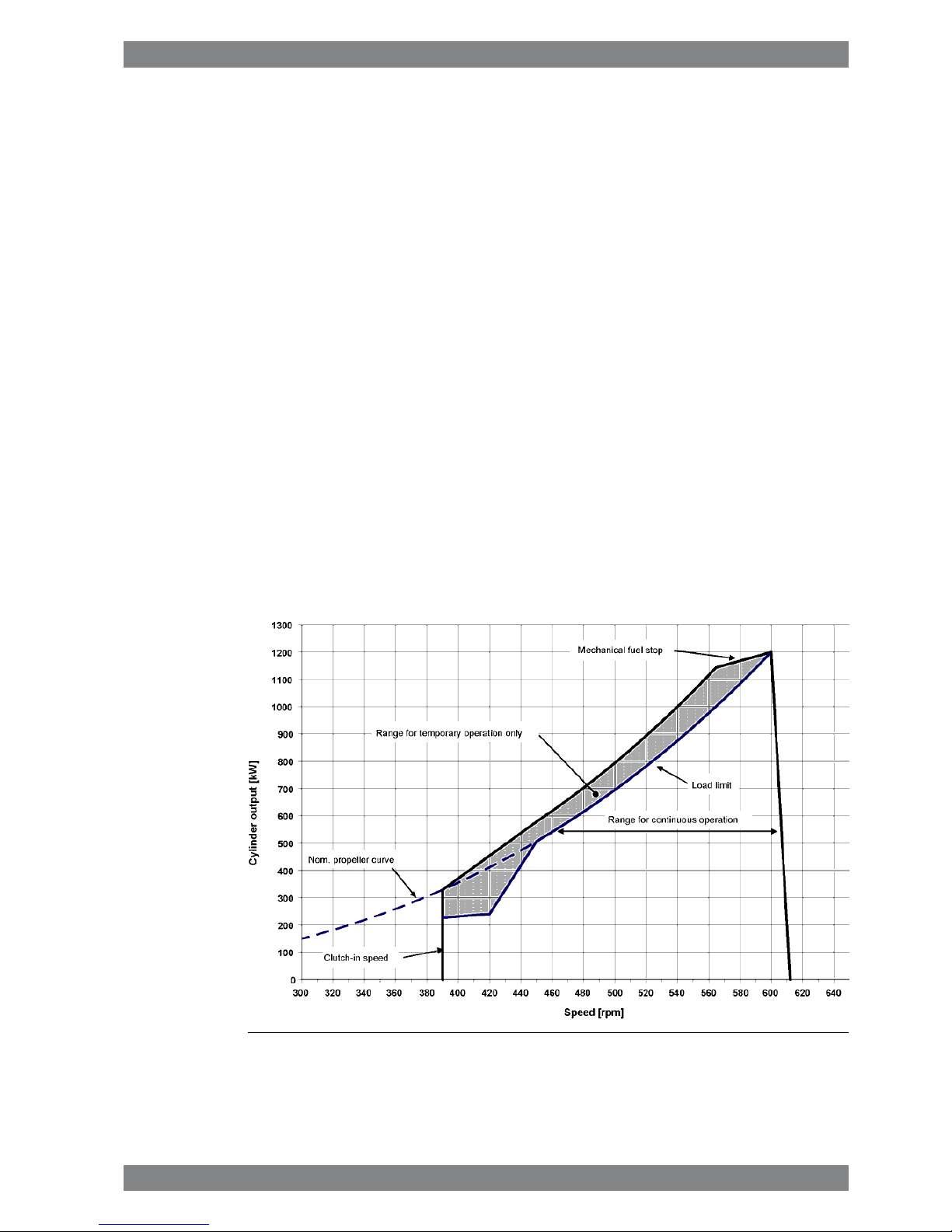
2.1 Engine operating range
Running below nominal speed the load must be limited according to the diagrams in this
chapter in order to maintain engine operating parameters within acceptable limits. Operation
in the shaded area is permitted only temporarily during transients. Minimum speed is indicated
in the diagram, but project specific limitations may apply.
2.1.1 Controllable pitch propellers
An automatic load control system is required to protect the engine from overload. The load
control reduces the propeller pitch automatically, when a pre-programmed load versus speed
curve (“engine limit curve”) is exceeded, overriding the combinator curve if necessary. The
engine load is derived from fuel rack position and actual engine speed (not speed demand).
The propulsion control must also include automatic limitation of the load increase rate.
Maximum loading rates can be found later in this chapter.
The propeller efficiency is highest at design pitch. It is common practice to dimension the
propeller so that the specified ship speed is attained with design pitch, nominal engine speed
and 85% output in the specified loading condition. The power demand from a possible shaft
generator or PTO must be taken into account. The 15% margin is a provision for weather
conditions and fouling of hull and propeller. An additional engine margin can be applied for
most economical operation of the engine, or to have reserve power.
Fig 2-1 Operating field for CP Propeller, IMO Tier 2, 1200 kW/cyl, 600 rpm
Wärtsilä 46F Product Guide - a19 - 1 December 2017 2-1
2. Operating RangesWärtsilä 46F Product Guide
2.2 Loading capacity
Controlled load increase is essential for highly supercharged diesel engines, because the
turbocharger needs time to accelerate before it can deliver the required amount of air. Sufficient
time to achieve even temperature distribution in engine components must also be ensured.
This is especially important for larger engines.
If the control system has only one load increase ramp, then the ramp for a preheated engine
should be used. The HT-water temperature in a preheated engine must be at least 60 ºC,
preferably 70 ºC, and the lubricating oil temperature must be at least 40 ºC.
The ramp for normal loading applies to engines that have reached normal operating
temperature.
Emergency loading may only be possible by activating an emergency function, which generates
visual and audible alarms in the control room and on the bridge.
The load should always be applied gradually in normal operation. Class rules regarding load
acceptance capability of diesel generators should not be interpreted as guidelines on how to
apply load in normal operation. The class rules define what the engine must be capable of, if
an unexpected event causes a sudden load step.
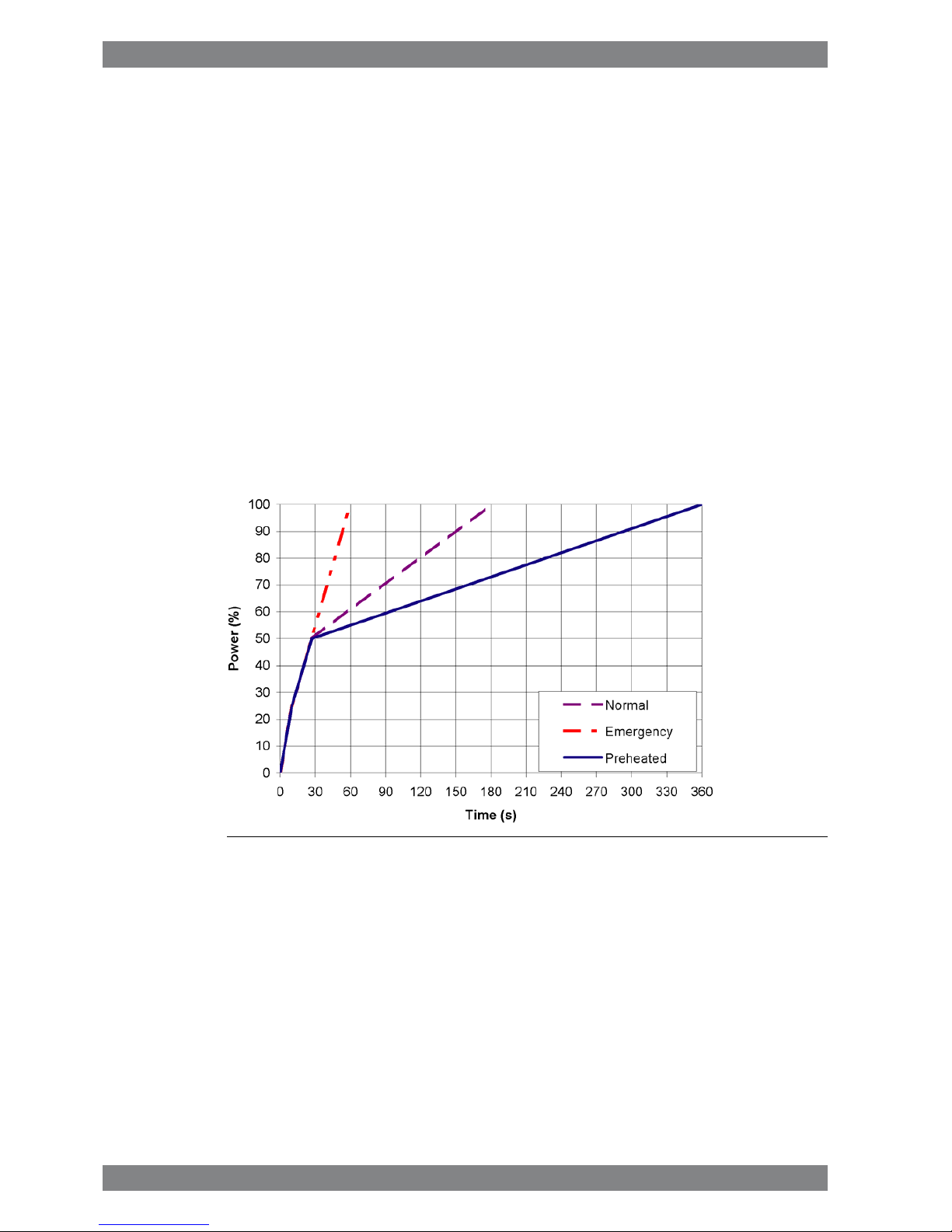
2.2.1 Mechanical propulsion, controllable pitch propeller (CPP)
Fig 2-2 Maximum load increase rates for variable speed engines
If minimum smoke during load increase is a major priority, slower loading rate than in the
diagram can be necessary below 50% load.
In normal operation the load should not be reduced from 100% to 0% in less than 15 seconds.
When absolutely necessary, the load can be reduced as fast as the pitch setting system can
react (overspeed due to windmilling must be considered for high speed ships).
2-2 Wärtsilä 46F Product Guide - a19 - 1 December 2017
Wärtsilä 46F Product Guide2. Operating Ranges
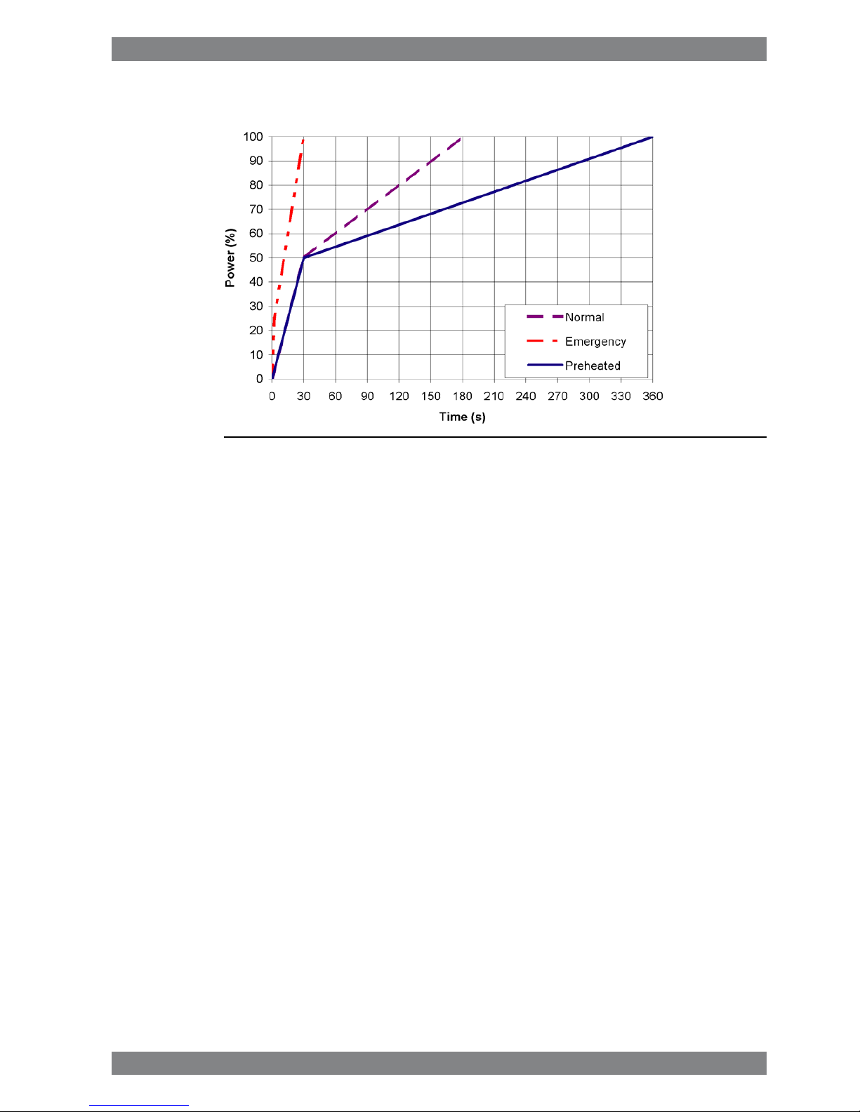
2.2.2 Diesel electric propulsion
Fig 2-3 Maximum load increase rates for engines operating at nominal speed
In normal operation the load should not be reduced from 100% to 0% in less than 15 seconds.
In an emergency situation the full load can be thrown off instantly.
The maximum deviation from steady state speed is less than 10%, when applying load
according to the emergency loading ramp. Load increase according to the normal ramp
correspondingly results in less than 3% speed deviation.
2.2.2.1 Maximum instant load steps
The electrical system must be designed so that tripping of breakers can be safely handled.
This requires that the engines are protected from load steps exceeding their maximum load
acceptance capability. The maximum permissible load step for an engine that has attained
normal operating temperature is 33% MCR. The resulting speed drop is less than 10% and
the recovery time to within 1% of the steady state speed at the new load level is max. 5
seconds.
When electrical power is restored after a black-out, consumers are reconnected in groups,
which may cause significant load steps. The engine must be allowed to recover for at least
10 seconds before applying the following load step, if the load is applied in maximum steps.
2.2.2.2 Start-up time
A diesel generator typically reaches nominal speed in about 25 seconds after the start signal.
The acceleration is limited by the speed control to minimise smoke during start-up.
2.3 Operation at low load and idling
The engine can be started, stopped and operated on heavy fuel under all operating conditions.
Continuous operation on heavy fuel is preferred rather than changing over to diesel fuel at low
load operation and manoeuvring. The following recommendations apply:
Absolute idling (declutched main engine, disconnected generator)
● Maximum 10 minutes if the engine is to be stopped after the idling. 3 minutes idling before
stop is recommended.
Wärtsilä 46F Product Guide - a19 - 1 December 2017 2-3
2. Operating RangesWärtsilä 46F Product Guide

● Maximum 6 hours if the engine is to be loaded after the idling.
Operation below 20 % load
● Maximum 100 hours continuous operation. At intervals of 100 operating hours the engine
must be loaded to minimum 70 % of the rated output.
Operation above 20 % load
● No restrictions.
2.4 Low air temperature
In cold conditions the following minimum inlet air temperatures apply:
● Starting + 5ºC
● Idling - 5ºC
● High load - 10ºC
The two-stage charge air cooler is useful for heating of the charge air during prolonged low
load operation in cold conditions. Sustained operation between 0 and 40% load can however
require special provisions in cold conditions to prevent too low HT-water temperature. If
necessary, the preheating arrangement can be designed to heat the running engine (capacity
to be checked).
For further guidelines, see chapter Combustion air system design.
2-4 Wärtsilä 46F Product Guide - a19 - 1 December 2017
Wärtsilä 46F Product Guide2. Operating Ranges
3. Technical Data
3.1 Introduction
This chapter contains technical data of the engine (heat balance, flows, pressures etc.) for
design of auxiliary systems. Further design criteria for external equipment and system layouts
are presented in the respective chapter.
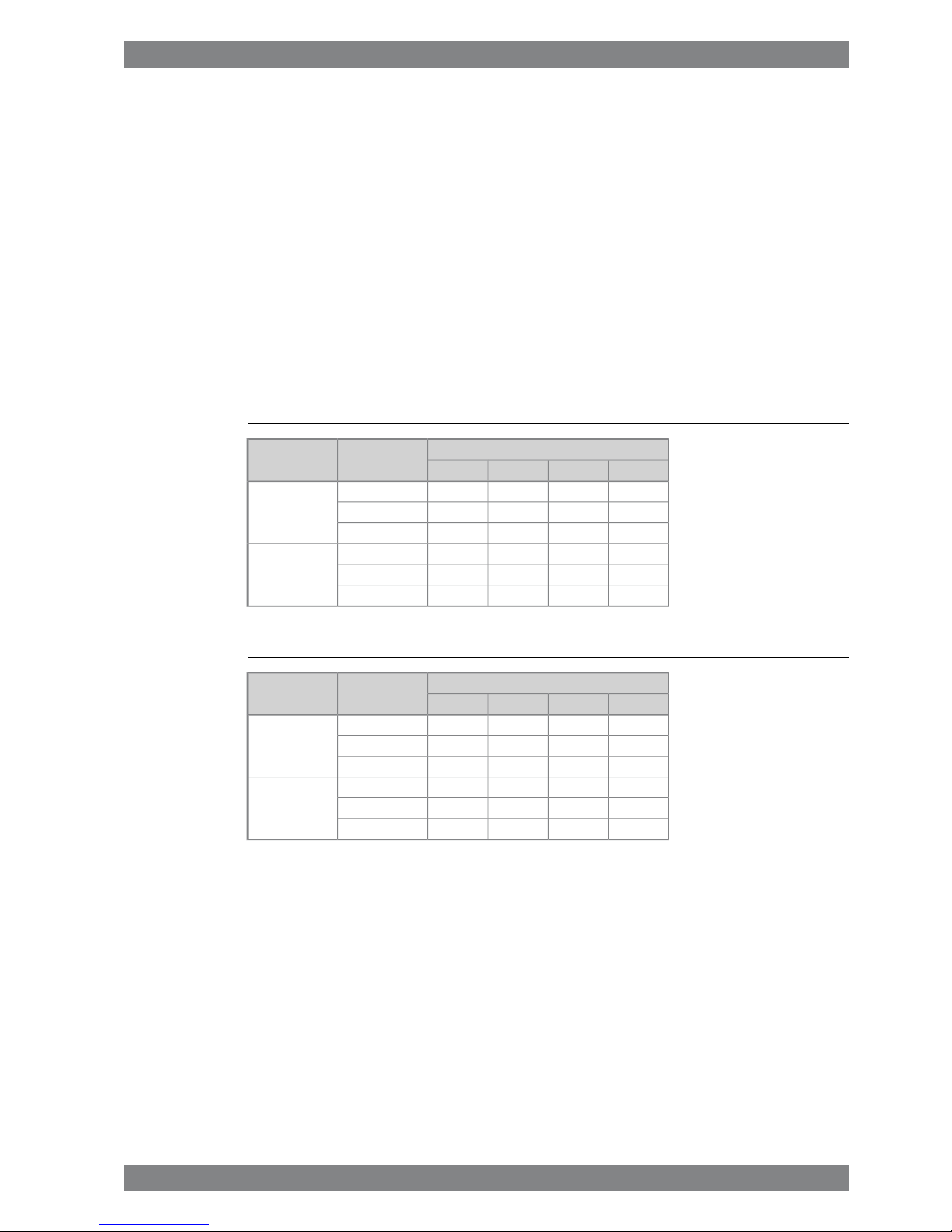
3.1.1 Engine driven pumps
The fuel consumption stated in the technical data tables is with engine driven pumps. The
increase in fuel consumption with engine driven pumps is given in the table below; correction
in g/kWh.
Table 3-1 Constant speed engines
Engine load [%]Engine driven
pumps
Application
507585100
-2.4-1.5-1.3-1.1Lube oil
Inline -0.7-0.4-0.4-0.3LT Water
-0.7-0.4-0.4-0.3HT Water
-1.6-1.2-1.0-1.0Lube oil
V-engine -0.3-0.3-0.3-0.3LT Water
-0.3-0.3-0.3-0.3HT Water
Table 3-2 Variable speed engines
Engine load [%]Engine driven
pumps
Application
507585100
-1.9-1.4-1.3-1.2Lube oil
Inline -0.3-0.3-0.3-0.3LT Water
-0.3-0.3-0.3-0.3HT Water
-1.6-1.2-1.0-1.0Lube oil
V-engine -0.3-0.3-0.3-0.3LT Water
-0.3-0.3-0.3-0.3HT Water
Wärtsilä 46F Product Guide - a19 - 1 December 2017 3-1
3. Technical DataWärtsilä 46F Product Guide
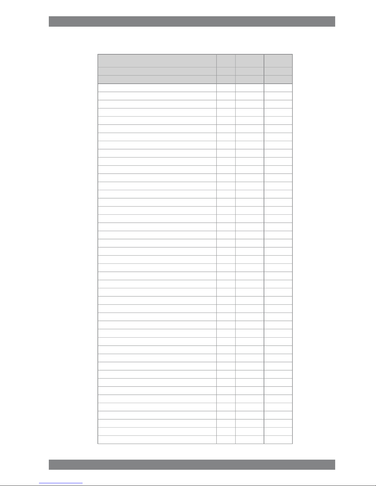
3.2 Wärtsilä 6L46F
DEMEWärtsilä 6L46F
12001200kWCylinder output
600600rpmEngine speed
72007200kWEngine output
2.492.49MPaMean effective pressure
Combustion air system (Note 1)
12.412.4kg/sFlow at 100% load
4545°CTemperature at turbocharger intake, max. (TE 600)
5050°CTemperature after air cooler, nom. (TE 601)
Exhaust gas system (Note 2)
13.0813.08kg/sFlow at 100% load
11.711.4kg/sFlow at 85% load
11.710.8kg/sFlow at 75% load
9.427.44kg/sFlow at 50% load
368368°CTemp. after turbo, 100% load (TE 517)
318322°CTemp. after turbo, 85% load (TE 517)
310323°CTemp. after turbo, 75% load (TE 517)
275327°CTemp. after turbo, 50% load (TE 517)
33kPaBackpressure, max.
927927mmCalculated pipe diameter for 35 m/s
Heat balance at 100% load (Note 3)
846846kWJacket water, HT-circuit
14881488kWCharge air, HT-circuit
762762kWCharge air, LT-circuit
756756kWLubricating oil, LT-circuit
210210kWRadiation
Fuel system (Note 4)
880...930880...930kPaPressure before injection pumps (PT 101) at 100% load - HFO
900...950900...950kPaPressure before injection pumps (PT 101) at 85% load - HFO
4.9...5.44.9...5.4m3/hFlow to engine, approx. - HFO
16...2416...24cStHFO viscosity before engine
140140°CMax. HFO temperature before engine (TE 101)
2.02.0cStMDF viscosity, min.
4545°CMax. MDF temperature before engine (TE 101)
4.54.5kg/hLeak fuel quantity (HFO), clean fuel at 100% load
22.522.5kg/hLeak fuel quantity (MDF), clean fuel at 100% load
179.6179.6g/kWhFuel consumption at 100% load
174.7173.4g/kWhFuel consumption at 85% load
183.6177.9g/kWhFuel consumption at 75% load
191.5181.0g/kWhFuel consumption at 50% load
Lubricating oil system
500500kPaPressure before bearings, nom. (PT 201)
3-2 Wärtsilä 46F Product Guide - a19 - 1 December 2017
Wärtsilä 46F Product Guide3. Technical Data
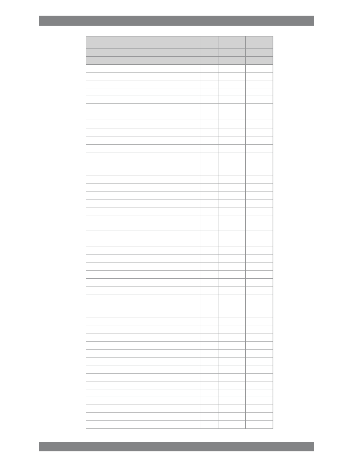
DEMEWärtsilä 6L46F
12001200kWCylinder output
600600rpmEngine speed
800800kPaPressure after pump, max.
4040kPaSuction ability main pump, including pipe loss, max.
8080kPaPriming pressure, nom. (PT 201)
5656°CTemperature before bearings, nom. (TE 201)
7575°CTemperature after engine, approx.
175191m3/hPump capacity (main), engine driven
158191m3/hPump capacity (main), electrically driven
130130m3/hOil flow through engine
3535m3/hPriming pump capacity
13.013.0m
3
Oil tank volume in separate system, min
0.70.7g/kWhOil consumption at 100% load, approx.
13501350l/minCrankcase ventilation flow rate at full load
0.40.4kPaCrankcase ventilation backpressure, max.
9.59.5lOil volume in turning device
1.71.7lOil volume in speed governor
High temperature cooling water system
250 + static250 + statickPaPressure at engine, after pump, nom. (PT 401)
530530kPaPressure at engine, after pump, max. (PT 401)
7474°CTemperature before cylinders, approx. (TE 401)
91...9591...95°CTemperature after charge air cooler, nom.
115115m3/hCapacity of engine driven pump, nom.
150150kPaPressure drop over engine, total
100100kPaPressure drop in external system, max.
70...15070...150kPaPressure from expansion tank
1.01.0m
3
Water volume in engine
Low temperature cooling water system
250 + static250 + statickPaPressure at engine, after pump, nom. (PT 451)
530530kPaPressure at engine, after pump, max. (PT 451)
3838°CTemperature before engine, max. (TE 451)
2525°CTemperature before engine, min. (TE 451)
115115m3/hCapacity of engine driven pump, nom.
5050kPaPressure drop over charge air cooler
2020kPaPressure drop over built-on lube oil cooler
3030kPaPressure drop over built-on temp. control valve
150150kPaPressure drop in external system, max.
70 ... 15070 ... 150kPaPressure from expansion tank
0.30.3m
3
Water volume in engine
Starting air system (Note 5)
30003000kPaPressure, nom. (PT 301)
15001500kPaPressure at engine during start, min. (20°C)
30003000kPaPressure, max. (PT 301)
18001800kPaLow pressure limit in air vessels
6.06.0Nm
3
Consumption per start at 20°C (successful start)
Wärtsilä 46F Product Guide - a19 - 1 December 2017 3-3
3. Technical DataWärtsilä 46F Product Guide

DEMEWärtsilä 6L46F
12001200kWCylinder output
600600rpmEngine speed
7.07.0Nm
3
Consumption per start at 20°C, (with slowturn)
Notes:
At ISO 15550 conditions (ambient air temperature 25°C, LT-water 25°C) and 100% load. Flow tolerance 5%.Note
1
At ISO 15550 conditions (ambient air temperature 25°C, LT-water 25°C). Flow tolerance 5% and temperature tolerance
15°C.
Note
2
At ISO 15550 conditions (ambient air temperature 25°C, LT-water 25°C) and 100% load. Tolerance for cooling water heat
10%, tolerance for radiation heat 30%. Fouling factors and a margin to be taken into account when dimensioning heat exchangers.
Note
3
According to ISO 15550, lower calorific value 42700 kJ/kg, with engine driven pumps (two cooling water + one lubricating
oil pumps). Tolerance 5%. The fuel consumption at 85 % load is guaranteed and the values at other loads are given for indication only.
Note
4
At manual starting the consumption may be 2...3 times lower.Note
5
ME = Engine driving propeller, variable speed
DE = Engine driving generator
Subject to revision without notice.
3-4 Wärtsilä 46F Product Guide - a19 - 1 December 2017
Wärtsilä 46F Product Guide3. Technical Data

3.3 Wärtsilä 7L46F
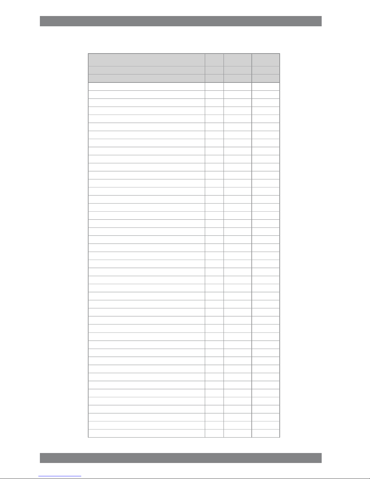
DEMEWärtsilä 7L46F
12001200kWCylinder output
600600rpmEngine speed
84008400kWEngine output
2.492.49MPaMean effective pressure
Combustion air system (Note 1)
14.614.6kg/sFlow at 100% load
4545°CTemperature at turbocharger intake, max. (TE 600)
5050°CTemperature after air cooler, nom. (TE 601)
Exhaust gas system (Note 2)
15.2615.26kg/sFlow at 100% load
13.6513.3kg/sFlow at 85% load
13.6512.6kg/sFlow at 75% load
10.998.68kg/sFlow at 50% load
368368°CTemp. after turbo, 100% load (TE 517)
318322°CTemp. after turbo, 85% load (TE 517)
310323°CTemp. after turbo, 75% load (TE 517)
275327°CTemp. after turbo, 50% load (TE 517)
33kPaBackpressure, max.
10011001mmCalculated pipe diameter for 35 m/s
Heat balance at 100% load (Note 3)
987987kWJacket water, HT-circuit
17361736kWCharge air, HT-circuit
889889kWCharge air, LT-circuit
882882kWLubricating oil, LT-circuit
245245kWRadiation
Fuel system (Note 4)
880...930880...930kPaPressure before injection pumps (PT 101) at 100% load - HFO
900...950900...950kPaPressure before injection pumps (PT101) at 85% load - HFO
5.7...6.35.7...6.3m3/hFlow to engine, approx - HFO
16...2416...24cStHFO viscosity before engine
140140°CMax. HFO temperature before engine (TE 101)
2.02.0cStMDF viscosity, min.
4545°CMax. MDF temperature before engine (TE 101)
5.25.2kg/hLeak fuel quantity (HFO), clean fuel at 100% load
26.526.5kg/hLeak fuel quantity (MDF), clean fuel at 100% load
179.6179.6g/kWhFuel consumption at 100% load
174.7173.4g/kWhFuel consumption at 85% load
183.6177.9g/kWhFuel consumption at 75% load
191.5181.0g/kWhFuel consumption at 50% load
Lubricating oil system
500500kPaPressure before bearings, nom. (PT 201)
Wärtsilä 46F Product Guide - a19 - 1 December 2017 3-5
3. Technical DataWärtsilä 46F Product Guide
DEMEWärtsilä 7L46F
12001200kWCylinder output
600600rpmEngine speed
800800kPaPressure after pump, max.
4040kPaSuction ability main pump, including pipe loss, max.
8080kPaPriming pressure, nom. (PT 201)
5656°CTemperature before bearings, nom. (TE 201)
7575°CTemperature after engine, approx.
191207m3/hPump capacity (main), engine driven
179207m3/hPump capacity (main), electrically driven
150150m3/hOil flow through engine
4545m3/hPriming pump capacity
15.015.0m
3
Oil tank volume in separate system, min
0.70.7g/kWhOil consumption at 100% load, approx.
16001600l/minCrankcase ventilation flow rate at full load
0.40.4kPaCrankcase ventilation backpressure, max.
9.59.5lOil volume in turning device
1.71.7lOil volume in speed governor
High temperature cooling water system
250 + static250 + statickPaPressure at engine, after pump, nom. (PT 401)
530530kPaPressure at engine, after pump, max. (PT 401)
7474°CTemperature before cylinders, approx. (TE 401)
91...9591...95°CTemperature after charge air cooler, nom.
150150m3/hCapacity of engine driven pump, nom.
150150kPaPressure drop over engine, total
100100kPaPressure drop in external system, max.
70...15070...150kPaPressure from expansion tank
1.31.3m
3
Water volume in engine
Low temperature cooling water system
250 + static250 + statickPaPressure at engine, after pump, nom. (PT 451)
530530kPaPressure at engine, after pump, max. (PT 451)
3838°CTemperature before engine, max. (TE 451)
2525°CTemperature before engine, min. (TE 451)
150150m3/hCapacity of engine driven pump, nom.
5050kPaPressure drop over charge air cooler
2020kPaPressure drop over built-on lube oil cooler
3030kPaPressure drop over built-on temp. control valve
150150kPaPressure drop in external system, max.
70 ... 15070 ... 150kPaPressure from expansion tank
0.40.4m
3
Water volume in engine
Starting air system (Note 5)
30003000kPaPressure, nom. (PT 301)
15001500kPaPressure at engine during start, min. (20°C)
30003000kPaPressure, max. (PT 301)
18001800kPaLow pressure limit in air vessels
7.07.0Nm
3
Consumption per start at 20°C (successful start)
3-6 Wärtsilä 46F Product Guide - a19 - 1 December 2017
Wärtsilä 46F Product Guide3. Technical Data

DEMEWärtsilä 7L46F
12001200kWCylinder output
600600rpmEngine speed
8.08.0Nm
3
Consumption per start at 20°C, (with slowturn)
Notes:
At ISO 15550 conditions (ambient air temperature 25°C, LT-water 25°C) and 100% load. Flow tolerance 5%.Note
1
At ISO 15550 conditions (ambient air temperature 25°C, LT-water 25°C). Flow tolerance 5% and temperature tolerance
15°C.
Note
2
At ISO 15550 conditions (ambient air temperature 25°C, LT-water 25°C) and 100% load. Tolerance for cooling water heat
10%, tolerance for radiation heat 30%. Fouling factors and a margin to be taken into account when dimensioning heat exchangers.
Note
3
According to ISO 15550, lower calorific value 42700 kJ/kg, with engine driven pumps (two cooling water + one lubricating
oil pumps). Tolerance 5%. The fuel consumption at 85 % load is guaranteed and the values at other loads are given for indication only.
Note
4
At manual starting the consumption may be 2...3 times lower.Note
5
ME = Engine driving propeller, variable speed
DE = Engine driving generator
Subject to revision without notice.
Wärtsilä 46F Product Guide - a19 - 1 December 2017 3-7
3. Technical DataWärtsilä 46F Product Guide

3.4 Wärtsilä 8L46F
DE
IMO Tier 2
ME
IMO Tier 2
Wärtsilä 8L46F
12001200kWCylinder output
600600rpmEngine speed
96009600kWEngine output
2.492.49MPaMean effective pressure
Combustion air system (Note 1)
16.616.6kg/sFlow at 100% load
4545°CTemperature at turbocharger intake, max. (TE 600)
5050°CTemperature after air cooler, nom. (TE 601)
Exhaust gas system (Note 2)
17.4417.44kg/sFlow at 100% load
15.615.2kg/sFlow at 85% load
15.614.4kg/sFlow at 75% load
12.569.92kg/sFlow at 50% load
368368°CTemp. after turbo, 100% load (TE 517)
318322°CTemp. after turbo, 85% load (TE 517)
310323°CTemp. after turbo, 75% load (TE 517)
275327°CTemp. after turbo, 50% load (TE 517)
33kPaBackpressure, max.
10701070mmCalculated pipe diameter for 35 m/s
Heat balance at 100% load (Note 3)
11281128kWJacket water, HT-circuit
19841984kWCharge air, HT-circuit
10161016kWCharge air, LT-circuit
10081008kWLubricating oil, LT-circuit
280280kWRadiation
Fuel system (Note 4)
880...930880...930kPaPressure before injection pumps (PT 101) at 100% load - HFO
900...950900...950kPaPressure before injection pumps (PT101) at 85% load - HFO
6.5...7.26.5...7.2m3/hFlow to engine, approx HFO
16...2416...24cStHFO viscosity before engine
140140°CMax. HFO temperature before engine (TE 101)
2.02.0cStMDF viscosity, min.
4545°CMax. MDF temperature before engine (TE 101)
6.06.0kg/hLeak fuel quantity (HFO), clean fuel at 100% load
30.030.0kg/hLeak fuel quantity (MDF), clean fuel at 100% load
179.6179.6g/kWhFuel consumption at 100% load
174.7173.4g/kWhFuel consumption at 85% load
183.6177.9g/kWhFuel consumption at 75% load
191.5181.0g/kWhFuel consumption at 50% load
Lubricating oil system
500500kPaPressure before bearings, nom. (PT 201)
3-8 Wärtsilä 46F Product Guide - a19 - 1 December 2017
Wärtsilä 46F Product Guide3. Technical Data
DE
IMO Tier 2
ME
IMO Tier 2
Wärtsilä 8L46F
12001200kWCylinder output
600600rpmEngine speed
800800kPaPressure after pump, max.
4040kPaSuction ability main pump, including pipe loss, max.
8080kPaPriming pressure, nom. (PT 201)
5656°CTemperature before bearings, nom. (TE 201)
7575°CTemperature after engine, approx.
207228m3/hPump capacity (main), engine driven
198228m3/hPump capacity (main), electrically driven
170170m3/hOil flow through engine
4545m3/hPriming pump capacity
17.017.0m
3
Oil tank volume in separate system, min
0.70.7g/kWhOil consumption at 100% load, approx.
17001700l/minCrankcase ventilation flow rate at full load
0.40.4kPaCrankcase ventilation backpressure, max.
9.59.5lOil volume in turning device
1.71.7lOil volume in speed governor
High temperature cooling water system
250 + static250 + statickPaPressure at engine, after pump, nom. (PT 401)
530530kPaPressure at engine, after pump, max. (PT 401)
7474°CTemperature before cylinders, approx. (TE 401)
91...9591...95°CTemperature after charge air cooler, nom.
150150m3/hCapacity of engine driven pump, nom.
150150kPaPressure drop over engine, total
100100kPaPressure drop in external system, max.
70...15070...150kPaPressure from expansion tank
1.41.4m
3
Water volume in engine
Low temperature cooling water system
250 + static250 + statickPaPressure at engine, after pump, nom. (PT 451)
530530kPaPressure at engine, after pump, max. (PT 451)
3838°CTemperature before engine, max. (TE 451)
2525°CTemperature before engine, min. (TE 451)
150150m3/hCapacity of engine driven pump, nom.
5050kPaPressure drop over charge air cooler
2020kPaPressure drop over built-on lube oil cooler
3030kPaPressure drop over built-on temp. control valve
150150kPaPressure drop in external system, max.
70 ... 15070 ... 150kPaPressure from expansion tank
0.40.4m
3
Water volume in engine
Starting air system (Note 5)
30003000kPaPressure, nom. (PT 301)
15001500kPaPressure at engine during start, min. (20°C)
30003000kPaPressure, max. (PT 301)
18001800kPaLow pressure limit in air vessels
8.08.0Nm
3
Consumption per start at 20°C (successful start)
Wärtsilä 46F Product Guide - a19 - 1 December 2017 3-9
3. Technical DataWärtsilä 46F Product Guide

DE
IMO Tier 2
ME
IMO Tier 2
Wärtsilä 8L46F
12001200kWCylinder output
600600rpmEngine speed
9.09.0Nm
3
Consumption per start at 20°C, (with slowturn)
Notes:
At ISO 15550 conditions (ambient air temperature 25°C, LT-water 25°C) and 100% load. Flow tolerance 5%.Note
1
At ISO 15550 conditions (ambient air temperature 25°C, LT-water 25°C). Flow tolerance 5% and temperature tolerance
15°C.
Note
2
At ISO 15550 conditions (ambient air temperature 25°C, LT-water 25°C) and 100% load. Tolerance for cooling water heat
10%, tolerance for radiation heat 30%. Fouling factors and a margin to be taken into account when dimensioning heat exchangers.
Note
3
According to ISO 15550, lower calorific value 42700 kJ/kg, with engine driven pumps (two cooling water + one lubricating
oil pumps). Tolerance 5%. The fuel consumption at 85 % load is guaranteed and the values at other loads are given for indication only.
Note
4
At manual starting the consumption may be 2...3 times lower.Note
5
ME = Engine driving propeller, variable speed
DE = Engine driving generator
Subject to revision without notice.
3-10 Wärtsilä 46F Product Guide - a19 - 1 December 2017
Wärtsilä 46F Product Guide3. Technical Data
3.5 Wärtsilä 9L46F
DE
IMO Tier 2
ME
IMO Tier 2
Wärtsilä 9L46F
12001200kWCylinder output
600600rpmEngine speed
1080010800kWEngine output
2.492.49MPaMean effective pressure
Combustion air system (Note 1)
18.818.8kg/sFlow at 100% load
4545°CTemperature at turbocharger intake, max. (TE 600)
5050°CTemperature after air cooler, nom. (TE 601)
Exhaust gas system (Note 2)
19.6219.62kg/sFlow at 100% load
17.5517.1kg/sFlow at 85% load
17.5516.2kg/sFlow at 75% load
14.1311.16kg/sFlow at 50% load
368368°CTemp. after turbo, 100% load (TE 517)
318322°CTemp. after turbo, 85% load (TE 517)
310323°CTemp. after turbo, 75% load (TE 517)
275327°CTemp. after turbo, 50% load (TE 517)
33kPaBackpressure, max.
11351135mmCalculated pipe diameter for 35 m/s
Heat balance at 100% load (Note 3)
12691269kWJacket water, HT-circuit
22322232kWCharge air, HT-circuit
11431143kWCharge air, LT-circuit
11341134kWLubricating oil, LT-circuit
315315kWRadiation
Fuel system (Note 4)
880...930880...930kPaPressure before injection pumps (PT 101) at 100% load - HFO
900...950900...950kPaPressure before injection pumps (PT101) at 85% load -HFO
7.3...8.17.3...8.1m3/hFlow to engine, approx - HFO
16...2416...24cStHFO viscosity before engine
140140°CMax. HFO temperature before engine (TE 101)
2.02.0cStMDF viscosity, min.
4545°CMax. MDF temperature before engine (TE 101)
6.86.8kg/hLeak fuel quantity (HFO), clean fuel at 100% load
34.034.0kg/hLeak fuel quantity (MDF), clean fuel at 100% load
179.6179.6g/kWhFuel consumption at 100% load
174.7173.4g/kWhFuel consumption at 85% load
183.6177.9g/kWhFuel consumption at 75% load
191.5181.0g/kWhFuel consumption at 50% load
Lubricating oil system
500500kPaPressure before bearings, nom. (PT 201)
Wärtsilä 46F Product Guide - a19 - 1 December 2017 3-11
3. Technical DataWärtsilä 46F Product Guide
DE
IMO Tier 2
ME
IMO Tier 2
Wärtsilä 9L46F
12001200kWCylinder output
600600rpmEngine speed
800800kPaPressure after pump, max.
4040kPaSuction ability main pump, including pipe loss, max.
8080kPaPriming pressure, nom. (PT 201)
5656°CTemperature before bearings, nom. (TE 201)
7575°CTemperature after engine, approx.
228253m3/hPump capacity (main), engine driven
218253m3/hPump capacity (main), electrically driven
190190m3/hOil flow through engine
5050m3/hPriming pump capacity
19.019.0m
3
Oil tank volume in separate system, min
0.70.7g/kWhOil consumption at 100% load, approx.
18001800l/minCrankcase ventilation flow rate at full load
0.40.4kPaCrankcase ventilation backpressure, max.
70.070.0lOil volume in turning device
1.71.7lOil volume in speed governor
High temperature cooling water system
250 + static250 + statickPaPressure at engine, after pump, nom. (PT 401)
530530kPaPressure at engine, after pump, max. (PT 401)
7474°CTemperature before cylinders, approx. (TE 401)
91...9591...95°CTemperature after charge air cooler, nom.
180180m3/hCapacity of engine driven pump, nom.
150150kPaPressure drop over engine, total
100100kPaPressure drop in external system, max.
70...15070...150kPaPressure from expansion tank
1.51.5m
3
Water volume in engine
Low temperature cooling water system
250 + static250 + statickPaPressure at engine, after pump, nom. (PT 451)
530530kPaPressure at engine, after pump, max. (PT 451)
3838°CTemperature before engine, max. (TE 451)
2525°CTemperature before engine, min. (TE 451)
180180m3/hCapacity of engine driven pump, nom.
5050kPaPressure drop over charge air cooler
2020kPaPressure drop over built-on lube oil cooler
3030kPaPressure drop over built-on temp. control valve
150150kPaPressure drop in external system, max.
70 ... 15070 ... 150kPaPressure from expansion tank
0.50.5m
3
Water volume in engine
Starting air system (Note 5)
30003000kPaPressure, nom. (PT 301)
15001500kPaPressure at engine during start, min. (20°C)
30003000kPaPressure, max. (PT 301)
18001800kPaLow pressure limit in air vessels
9.09.0Nm
3
Consumption per start at 20°C (successful start)
3-12 Wärtsilä 46F Product Guide - a19 - 1 December 2017
Wärtsilä 46F Product Guide3. Technical Data

DE
IMO Tier 2
ME
IMO Tier 2
Wärtsilä 9L46F
12001200kWCylinder output
600600rpmEngine speed
10.010.0Nm
3
Consumption per start at 20°C, (with slowturn)
Notes:
At ISO 15550 conditions (ambient air temperature 25°C, LT-water 25°C) and 100% load. Flow tolerance 5%.Note
1
At ISO 15550 conditions (ambient air temperature 25°C, LT-water 25°C). Flow tolerance 5% and temperature tolerance
15°C.
Note
2
At ISO 15550 conditions (ambient air temperature 25°C, LT-water 25°C) and 100% load. Tolerance for cooling water heat
10%, tolerance for radiation heat 30%. Fouling factors and a margin to be taken into account when dimensioning heat exchangers.
Note
3
According to ISO 15550, lower calorific value 42700 kJ/kg, with engine driven pumps (two cooling water + one lubricating
oil pumps). Tolerance 5%. The fuel consumption at 85 % load is guaranteed and the values at other loads are given for indication only.
Note
4
At manual starting the consumption may be 2...3 times lower.Note
5
ME = Engine driving propeller, variable speed
DE = Engine driving generator
Subject to revision without notice.
Wärtsilä 46F Product Guide - a19 - 1 December 2017 3-13
3. Technical DataWärtsilä 46F Product Guide
3.6 Wärtsilä 12V46F
DE
IMO Tier 2
ME
IMO Tier 2
Wärtsilä 12V46F
12001200kWCylinder output
600600rpmEngine speed
1440014400kWEngine output
2.492.49MPaMean effective pressure
Combustion air system (Note 1)
25.025.0kg/sFlow at 100% load
4545°CTemperature at turbocharger intake, max. (TE 600)
5050°CTemperature after air cooler, nom. (TE 601)
Exhaust gas system (Note 2)
26.1626.16kg/sFlow at 100% load
23.422.8kg/sFlow at 85% load
23.421.6kg/sFlow at 75% load
18.8414.88kg/sFlow at 50% load
366366°CTemp. after turbo, 100% load (TE 517)
316320°CTemp. after turbo, 85% load (TE 517)
309322°CTemp. after turbo, 75% load (TE 517)
273325°CTemp. after turbo, 50% load (TE 517)
33kPaBackpressure, max.
13091309mmCalculated pipe diameter for 35 m/s
Heat balance at 100% load (Note 3)
16321632kWJacket water, HT-circuit
29762976kWCharge air, HT-circuit
15241524kWCharge air, LT-circuit
14641464kWLubricating oil, LT-circuit
420420kWRadiation
Fuel system (Note 4)
880...930880...930kPaPressure before injection pumps (PT 101) at 100% load - HFO
900...950900...950kPaPressure before injection pumps (PT101) at 85% load - HFO
9.8...10.89.8...10.8m3/hFlow to engine, approx - HFO
16...2416...24cStHFO viscosity before engine
140140°CMax. HFO temperature before engine (TE 101)
2.02.0cStMDF viscosity, min.
4545°CMax. MDF temperature before engine (TE 101)
9.09.0kg/hLeak fuel quantity (HFO), clean fuel at 100% load
45.045.0kg/hLeak fuel quantity (MDF), clean fuel at 100% load
178.7178.7g/kWhFuel consumption at 100% load
173.7172.5g/kWhFuel consumption at 85% load
182.7177.0g/kWhFuel consumption at 75% load
190.6180.1g/kWhFuel consumption at 50% load
Lubricating oil system
500500kPaPressure before bearings, nom. (PT 201)
3-14 Wärtsilä 46F Product Guide - a19 - 1 December 2017
Wärtsilä 46F Product Guide3. Technical Data

DE
IMO Tier 2
ME
IMO Tier 2
Wärtsilä 12V46F
12001200kWCylinder output
600600rpmEngine speed
800800kPaPressure after pump, max.
4040kPaSuction ability main pump, including pipe loss, max.
8080kPaPriming pressure, nom. (PT 201)
5656°CTemperature before bearings, nom. (TE 201)
7575°CTemperature after engine, approx.
260306m3/hPump capacity (main), engine driven
210259m3/hPump capacity (main), electrically driven
200200m3/hOil flow through engine
7070m3/hPriming pump capacity
22.522.5m
3
Oil tank volume in separate system, min
0.70.7g/kWhOil consumption at 100% load, approx.
35403540l/minCrankcase ventilation flow rate at full load
0.40.4kPaCrankcase ventilation backpressure, max.
70.070.0lOil volume in turning device
7.17.1lOil volume in speed governor
High temperature cooling water system
250 + static250 + statickPaPressure at engine, after pump, nom. (PT 401)
530530kPaPressure at engine, after pump, max. (PT 401)
7474°CTemperature before cylinders, approx. (TE 401)
91...9591...95°CTemperature after charge air cooler, nom.
210210m3/hCapacity of engine driven pump, nom.
150150kPaPressure drop over engine, total
100100kPaPressure drop in external system, max.
70...15070...150kPaPressure from expansion tank
2.02.0m
3
Water volume in engine
Low temperature cooling water system
250 + static250 + statickPaPressure at engine, after pump, nom. (PT 451)
530530kPaPressure at engine, after pump, max. (PT 451)
3838°CTemperature before engine, max. (TE 451)
2525°CTemperature before engine, min. (TE 451)
210210m3/hCapacity of engine driven pump, nom.
5050kPaPressure drop over charge air cooler
2020kPaPressure drop over built-on lube oil cooler
3030kPaPressure drop over built-on temp. control valve
150150kPaPressure drop in external system, max.
70 ... 15070 ... 150kPaPressure from expansion tank
0.60.6m
3
Water volume in engine
Starting air system (Note 5)
30003000kPaPressure, nom. (PT 301)
15001500kPaPressure at engine during start, min. (20°C)
30003000kPaPressure, max. (PT 301)
18001800kPaLow pressure limit in air vessels
12.012.0Nm
3
Consumption per start at 20°C (successful start)
Wärtsilä 46F Product Guide - a19 - 1 December 2017 3-15
3. Technical DataWärtsilä 46F Product Guide

DE
IMO Tier 2
ME
IMO Tier 2
Wärtsilä 12V46F
12001200kWCylinder output
600600rpmEngine speed
15.015.0Nm
3
Consumption per start at 20°C, (with slowturn)
Notes:
At ISO 15550 conditions (ambient air temperature 25°C, LT-water 25°C) and 100% load. Flow tolerance 5%.Note
1
At ISO 15550 conditions (ambient air temperature 25°C, LT-water 25°C). Flow tolerance 5% and temperature tolerance
15°C.
Note
2
At ISO 15550 conditions (ambient air temperature 25°C, LT-water 25°C) and 100% load. Tolerance for cooling water heat
10%, tolerance for radiation heat 30%. Fouling factors and a margin to be taken into account when dimensioning heat exchangers.
Note
3
According to ISO 15550, lower calorific value 42700 kJ/kg, with engine driven pumps (two cooling water + one lubricating
oil pumps). Tolerance 5%. The fuel consumption at 85 % load is guaranteed and the values at other loads are given for indication only.
Note
4
At manual starting the consumption may be 2...3 times lower.Note
5
ME = Engine driving propeller, variable speed
DE = Engine driving generator
Subject to revision without notice.
3-16 Wärtsilä 46F Product Guide - a19 - 1 December 2017
Wärtsilä 46F Product Guide3. Technical Data
 Loading...