

Page 1

PRODUCT GUIDE
Wärtsilä 31DF
Page 2

© Copyright by WÄRTSILÄ FINLAND Oy
All rights reserved. No part of this booklet may be reproduced or copied in any form or by any means (electronic,
mechanical, graphic, photocopying, recording, taping or other information retrieval systems) without the prior written
permission of the copyright owner.
THIS PUBLICATION IS DESIGNED TO PROVIDE AN ACCURATE AND AUTHORITATIVE INFORMATION WITH
REGARD TO THE SUBJECT-MATTER COVERED AS WAS AVAILABLE AT THE TIME OF PRINTING. HOWEVER,THE
PUBLICATION DEALS WITH COMPLICATED TECHNICAL MATTERS SUITED ONLY FOR SPECIALISTS IN THE
AREA, AND THE DESIGN OF THE SUBJECT-PRODUCTS IS SUBJECT TO REGULAR IMPROVEMENTS,
MODIFICATIONS AND CHANGES. CONSEQUENTLY, THE PUBLISHER AND COPYRIGHT OWNER OF THIS
PUBLICATION CAN NOT ACCEPT ANY RESPONSIBILITY OR LIABILITY FOR ANY EVENTUAL ERRORS OR
OMISSIONS IN THIS BOOKLET OR FOR DISCREPANCIES ARISING FROM THE FEATURES OF ANY ACTUAL ITEM
IN THE RESPECTIVE PRODUCT BEING DIFFERENT FROMTHOSE SHOWN IN THIS PUBLICATION. THE PUBLISHER
AND COPYRIGHT OWNER SHALL UNDER NO CIRCUMSTANCES BE HELD LIABLE FOR ANY FINANCIAL
CONSEQUENTIAL DAMAGES OR OTHER LOSS, OR ANY OTHER DAMAGE OR INJURY, SUFFERED BY ANY
PARTY MAKING USE OF THIS PUBLICATION OR THE INFORMATION CONTAINED HEREIN.
Copyright text
COPYRIGHT © 2019 BY WÄRTSILÄ FINLAND Oy
ALL RIGHTS RESERVED. NO PART OF THIS PUBLICATION MAY BE REPRODUCED OR COPIED IN ANY FORM
OR BY ANY MEANS, WITHOUT PRIOR WRITTEN PERMISSION OF THE COPYRIGHT OWNER.
Page 3

Introduction
This Product Guide provides data and system proposals for the early design
phase of marine engine installations. For contracted projects specific
instructions for planning the installation are always delivered. Any data and
information herein is subject to revision without notice. This 01/2019 issue
replaces all previous issues of the Wärtsilä 31DF Project Guides.
Wärtsilä, Marine Solutions
Vaasa, March 2019
DBAE248994 iii
IntroductionWärtsilä 31DF Product Guide
Page 4

This page intentionally left blank
Page 5

Table of contents
1-11. Main Data and Outputs ............................................................................................................................
1-11.1 Maximum continuous output ...............................................................................................................
1-21.2 Reference conditions ...........................................................................................................................
1-21.3 Operation in inclined position (only for Marine Solutions engines) ......................................................
1-31.4 Dimensions and weights .....................................................................................................................
2-12. Operating Ranges ....................................................................................................................................
2-12.1 Engine operating range ........................................................................................................................
2-22.2 Loading capacity ..................................................................................................................................
2-82.3 Low load operation ...............................................................................................................................
2-102.4 Low air temperature ............................................................................................................................
3-13. Technical Data ..........................................................................................................................................
3-13.1 Introduction ..........................................................................................................................................
3-33.2 Wärtsilä 8V31DF ...................................................................................................................................
3-113.3 Wärtsilä 10V31DF .................................................................................................................................
3-193.4 Wärtsilä 12V31DF .................................................................................................................................
3-273.5 Wärtsilä 14V31DF .................................................................................................................................
3-353.6 Wärtsilä 16V31DF .................................................................................................................................
4-14. Description of the Engine ........................................................................................................................
4-14.1 Definitions .............................................................................................................................................
4-14.2 Main components and systems ...........................................................................................................
4-64.3 Time between Inspection or Overhaul & Expected Life Time ..............................................................
4-74.4 Engine storage .....................................................................................................................................
5-15. Piping Design, Treatment and Installation .............................................................................................
5-15.1 Pipe dimensions ...................................................................................................................................
5-25.2 Trace heating ........................................................................................................................................
5-25.3 Pressure class ......................................................................................................................................
5-35.4 Pipe class .............................................................................................................................................
5-45.5 Insulation ..............................................................................................................................................
5-45.6 Local gauges ........................................................................................................................................
5-45.7 Cleaning procedures ............................................................................................................................
5-65.8 Flexible pipe connections .....................................................................................................................
5-85.9 Clamping of pipes ................................................................................................................................
6-16. Fuel Oil System .........................................................................................................................................
6-16.1 Acceptable fuel characteristics ............................................................................................................
6-96.2 Operating principles .............................................................................................................................
6-106.3 Fuel gas system ...................................................................................................................................
6-186.4 External fuel oil system ........................................................................................................................
7-17. Lubricating Oil System ............................................................................................................................
7-17.1 Lubricating oil requirements .................................................................................................................
7-27.2 External lubricating oil system .............................................................................................................
7-87.3 Crankcase ventilation system .............................................................................................................
7-107.4 Flushing instructions ............................................................................................................................
8-18. Compressed Air System ..........................................................................................................................
8-18.1 Instrument air quality ............................................................................................................................
8-18.2 External compressed air system ..........................................................................................................
DBAE248994 v
Table of contentsWärtsilä 31DF Product Guide
Page 6

9-19. Cooling Water System .............................................................................................................................
9-19.1 Water quality ........................................................................................................................................
9-29.2 External cooling water system .............................................................................................................
10-110. Combustion Air System .........................................................................................................................
10-110.1 Engine room ventilation ......................................................................................................................
10-210.2 Combustion air system design ...........................................................................................................
11-111. Exhaust Gas System ..............................................................................................................................
11-111.1 Exhaust gas outlet ..............................................................................................................................
11-311.2 External exhaust gas system .............................................................................................................
12-112. Turbocharger Cleaning ..........................................................................................................................
12-112.1 Turbine cleaning system .....................................................................................................................
12-212.2 Compressor cleaning system .............................................................................................................
13-113. Exhaust Emissions .................................................................................................................................
13-113.1 Dual fuel engine exhaust components ...............................................................................................
13-113.2 Marine exhaust emissions legislation .................................................................................................
13-113.3 Methods to reduce exhaust emissions ..............................................................................................
14-114. Automation System ................................................................................................................................
14-114.1 Technical data and system overview .................................................................................................
14-714.2 Functions ...........................................................................................................................................
14-1114.3 Alarm and monitoring signals .............................................................................................................
14-1114.4 Electrical consumers ..........................................................................................................................
14-1314.5 System requirements and guidelines for diesel-electric propulsion ..................................................
15-115. Foundation ..............................................................................................................................................
15-115.1 Steel structure design ........................................................................................................................
15-115.2 Mounting of main engines ..................................................................................................................
15-415.3 Mounting of generating sets ..............................................................................................................
15-515.4 Flexible pipe connections ...................................................................................................................
16-116. Vibration and Noise ................................................................................................................................
16-116.1 External forces & couples ...................................................................................................................
16-416.2 Mass moments of inertia ....................................................................................................................
16-416.3 Air borne noise ...................................................................................................................................
16-416.4 Exhaust noise .....................................................................................................................................
17-117. Power Transmission ...............................................................................................................................
17-117.1 Flexible coupling ................................................................................................................................
17-117.2 Torque flange ......................................................................................................................................
17-117.3 Clutch .................................................................................................................................................
17-117.4 Shaft locking device ...........................................................................................................................
17-217.5 Input data for torsional vibration calculations ....................................................................................
17-317.6 Turning gear ........................................................................................................................................
18-118. Engine Room Layout ..............................................................................................................................
18-118.1 Crankshaft distances ..........................................................................................................................
18-518.2 Space requirements for maintenance ................................................................................................
18-518.3 Transportation and storage of spare parts and tools .........................................................................
18-518.4 Required deck area for service work ..................................................................................................
19-119. Transport Dimensions and Weights .....................................................................................................
19-119.1 Lifting of main engines .......................................................................................................................
19-219.2 Lifting of generating sets ....................................................................................................................
19-319.3 Engine components ...........................................................................................................................
vi DBAE248994
Wärtsilä 31DF Product GuideTable of contents
Page 7

20-120. Product Guide Attachments ..................................................................................................................
21-121. ANNEX .....................................................................................................................................................
21-121.1 Unit conversion tables ........................................................................................................................
21-221.2 Collection of drawing symbols used in drawings ...............................................................................
DBAE248994 vii
Table of contentsWärtsilä 31DF Product Guide
Page 8

This page intentionally left blank
Page 9

1. Main Data and Outputs
The Wärtsilä 31DF is a 4-stroke, non-reversible, turbocharged and intercooled diesel engine
with direct fuel injection.
310 mmCylinder bore ........................
430 mmStroke ...................................
2 inlet valves, 2 exhaust valvesNumber of valves .................
8, 10, 12, 14 and 16Cylinder configuration .........
50°V-angle .................................
Clockwise, counterclockwiseDirection of rotation .............
720, 750 rpmSpeed ...................................
10.32 - 10.75 m/sMean piston speed ...............
1.1 Maximum continuous output
Table 1-1 Rating table for Wärtsilä 31DF
Generating setsMain enginesCylinder
configuration
750 rpm720 rpm750 rpm
Generator [kVA]Engine [kW]Generator [kVA]Engine [kW][kW]
52804400509042404400W 8V31DF
66005500636053005500W 10V31DF
79206600763063606600W 12V31DF
92407700890074207700W 14V31DF
1056088001018084808800W 16V31DF
The mean effective pressure Pe can be calculated as follows:
where:
mean effective pressure [bar]Pe =
output per cylinder [kW]P =
engine speed [r/min]n =
cylinder diameter [mm]D =
length of piston stroke [mm]L =
operating cycle (4)c =
DBAE248994 1-1
1. Main Data and OutputsWärtsilä 31DF Product Guide
Page 10

1.2 Reference conditions
The output is available within a range of ambient conditions and coolant temperatures specified
in the chapter Technical Data. The required fuel quality for maximum output is specified in the
section Fuel characteristics. For ambient conditions or fuel qualities outside the specification,
the output may have to be reduced.
The specific fuel consumption is stated in the chapter Technical Data. The statement applies
to engines operating in ambient conditions according to ISO 15550:2002 (E).
100 kPatotal barometric pressure
25 °Cair temperature
30 %relative humidity
25 °Ccharge air coolant temperature
Correction factors for the fuel oil consumption in other ambient conditions are given in standard
ISO 15550:2002 (E).
1.3 Operation ininclined position (onlyfor Marine Solutions
engines)
The engine is designed to ensure proper engine operation at inclination positions. Inclination
angle according to IACS requirement M46.2 (1982) (Rev.1 June 2002) - Main and auxiliary
machinery.
Max. inclination angles at which the engine will operate satisfactorily:
Table 1-2 Inclination with Normal Oil Sump
15°
●
Permanent athwart ship inclinations (list)
22.5°
●
Temporary athwart ship inclinations (roll)
10°
●
Permanent fore and aft inclinations (trim)
10°
●
Temporary fore and aft inclinations (pitch)
1-2 DBAE248994
Wärtsilä 31DF Product Guide1. Main Data and Outputs
Page 11
1.4 Dimensions and weights
1.4.1 Main engines
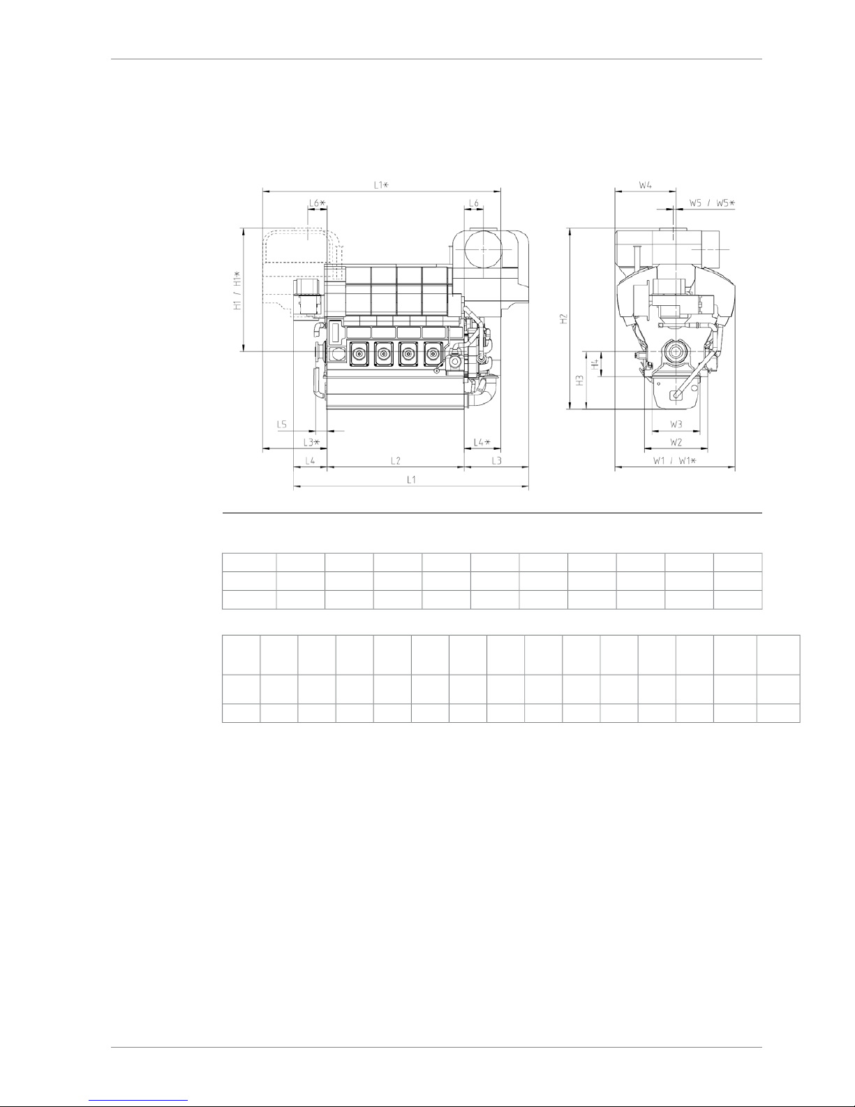
Fig 1-1 W8V31 & W10V31 Main engine dimensions
L6*L6L5L4*L4L3*L3L2L1*L1Engine
50050030098687716501650356061966087W8V31
50050030098687716501650420068366727W10V31
Weight
Liquids
Weight
Engine
**
W5*W5W4W3W2W1*W1H4H3H2H1*H1Engine
3.353.5 /
54.2*
-6767158511531600311531156501496470132053205W8V31
3.9562,2-6767158511531600311531156501496470132053205W10V31
DBAE248994 1-3
1. Main Data and OutputsWärtsilä 31DF Product Guide
Page 12
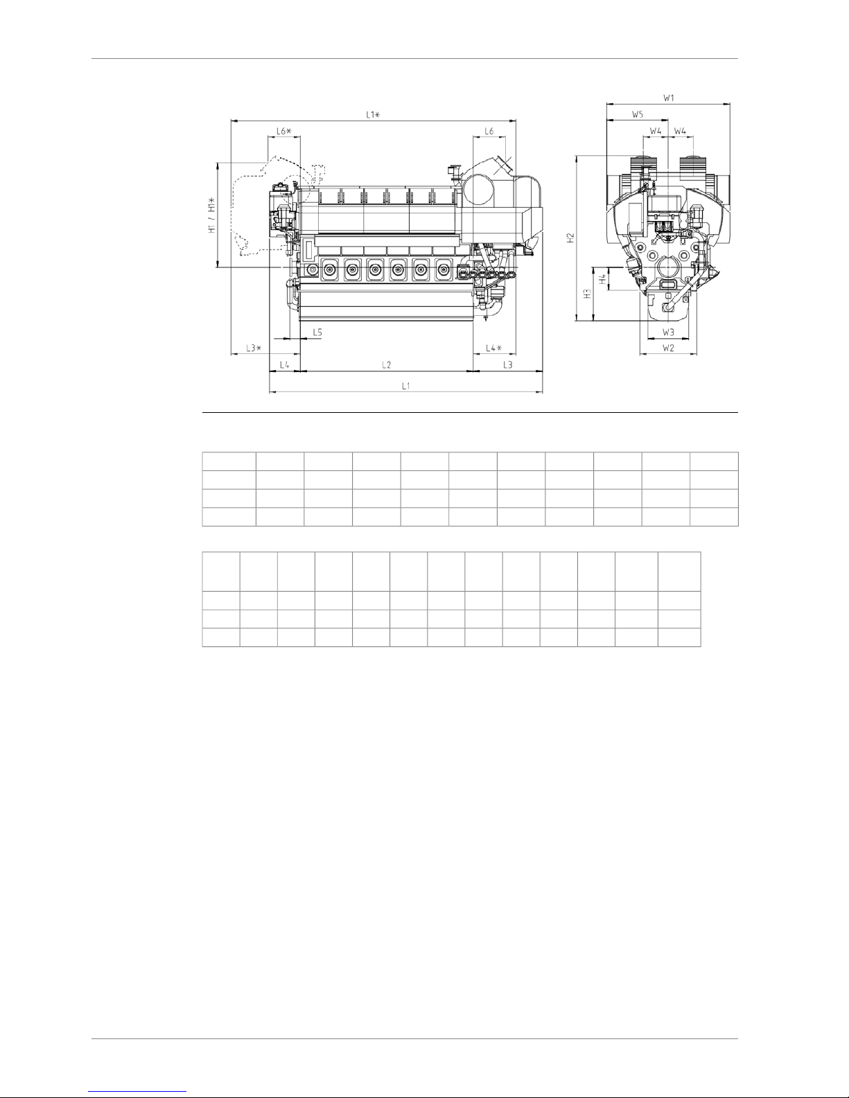
Fig 1-2 W12V31, W14V31 & W16V31 Main engine dimensions
L6*L6L5L4*L4L3*L3L2L1*L1Engine
9089083001250100020002000484080907840W12V31
9089083001250100020002000548087308480W14V31
9089083001250100020002000612093709120W16V31
Weight
Liquids
Weight
Engine
**
W5W4W3W2W1H4H3H2H1*H1Engine
4.9572.817506981153160035006501496463329262926W12V31
5.579.817506981153160035006501496463329262926W14V31
6.2587.917506981153160035006501496463329262926W16V31
1-4 DBAE248994
Wärtsilä 31DF Product Guide1. Main Data and Outputs
Page 13

Total length of engineL1
Length of the engine blockL2
Length from the engine block to the outer most point in turbocharger endL3
Length from the engine block to the outer most point in non-turbocharger endL4
Length from engine block to crankshaft flangeL5
Length from engine block to center of exhaust gas outletL6
Height from the crankshaft centerline to center of exhaust gas outletH1
Total height of engine (normal wet sump)H2
Height from crankshaft centerline to bottom of the oil sump (normal wet sump)H3
Height from the crankshaft centerline to engine feet (fixed mounted)H4
Total width of engineW1
Width of engine block at the engine feetW2
Width of oil sumpW3
Width from crankshaft centerline to center of exhaust gas outletW4
Width from crankshaft centerline to the outer most point of the engineW5
* Turbocharger at flywheel end;
** Weight without liquids, damper and flywheel (as a rule of thumb, add 60kg per cylinder on
top of 8 and or 10V engine weight or, add 50kg per cylinder for 12, 14 and 16V engines for
additional gas components weight);
All dimensions in mm, weights in tonne.
DBAE248994 1-5
1. Main Data and OutputsWärtsilä 31DF Product Guide
Page 14

This page intentionally left blank
Page 15
2. Operating Ranges
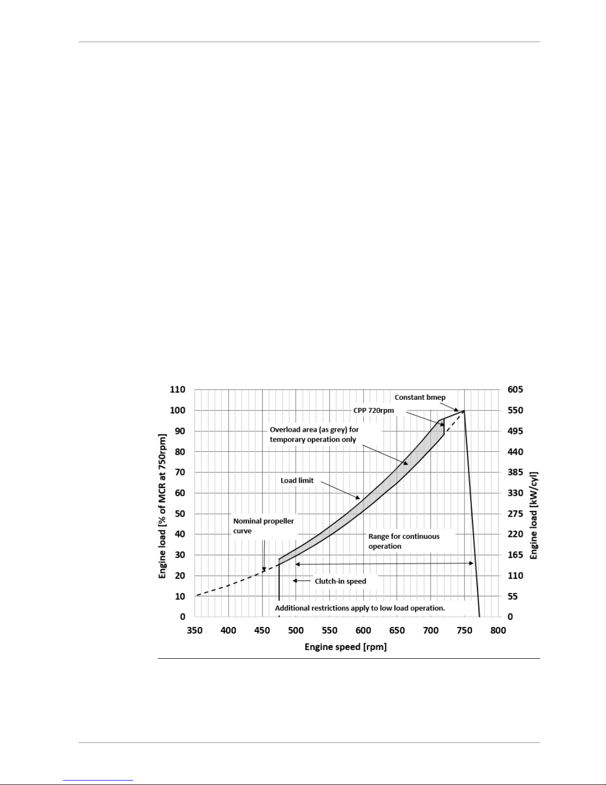
2.1 Engine operating range
Running below nominal speed the load must be limited according to the diagrams in this
chapter in order to maintain engine operating parameters within acceptable limits. Operation
in the shaded area is permitted only temporarily during transients. Minimum speed is indicated
in the diagram, but project specific limitations may apply.
2.1.1 Controllable pitch propellers
An automatic load control system is required to protect the engine from overload. The load
control reduces the propeller pitch automatically, when a pre-programmed load versus speed
curve (“engine limit curve”) is exceeded, overriding the combinator curve if necessary. Engine
load is determined from measured shaft power and actual engine speed. The shaft power
meter is Wärtsilä supply.
The propeller efficiency is highest at design pitch. It is common practice to dimension the
propeller so that the specified ship speed is attained with design pitch, nominal engine speed
and 85% output in the specified loading condition. The power demand from a possible shaft
generator or PTO must be taken into account. The 15% margin is a provision for weather
conditions and fouling of hull and propeller. An additional engine margin can be applied for
most economical operation of the engine, or to have reserve power.
The propulsion control must also include automatic limitation of the load increase rate.
Maximum loading rates can be found later in this chapter.
Fig 2-1 Operating field for CP Propeller (DAAF389037B)
DBAE248994 2-1
2. Operating RangesWärtsilä 31DF Product Guide
Page 16

NOTE
1) Valid for both gas operation and diesel operation.
2) Minimum engine speed is restricted to 472rpm with engine driven oil pump.
3) Additional restrictions apply to low load operation.
4) Project specific idling and clutch in speed depends on clutch, gearbox and the
Torsional Vibration Calculations.
Remarks: The maximum output may have to be reduced depending on gas properties and
gas pressure. The permissible output will in such case be reduced with same percentage at
all revolution speeds.
2.2 Loading capacity
Controlled load increase is essential for highly supercharged diesel engines, because the
turbocharger needs time to accelerate before it can deliver the required amount of air. A slower
loading ramp than the maximum capability of the engine permits a more even temperature
distribution in engine components during transients.
The engine can be loaded immediately after start, provided that the engine is pre-heated to:
● High Temperature (HT) water temperature is minimum 70°C
● Lubricating oil temperature is minimum 40°C
The ramp for normal loading applies to engines that have reached normal operating
temperature.
2-2 DBAE248994
Wärtsilä 31DF Product Guide2. Operating Ranges
Page 17
2.2.1 Mechanical propulsion
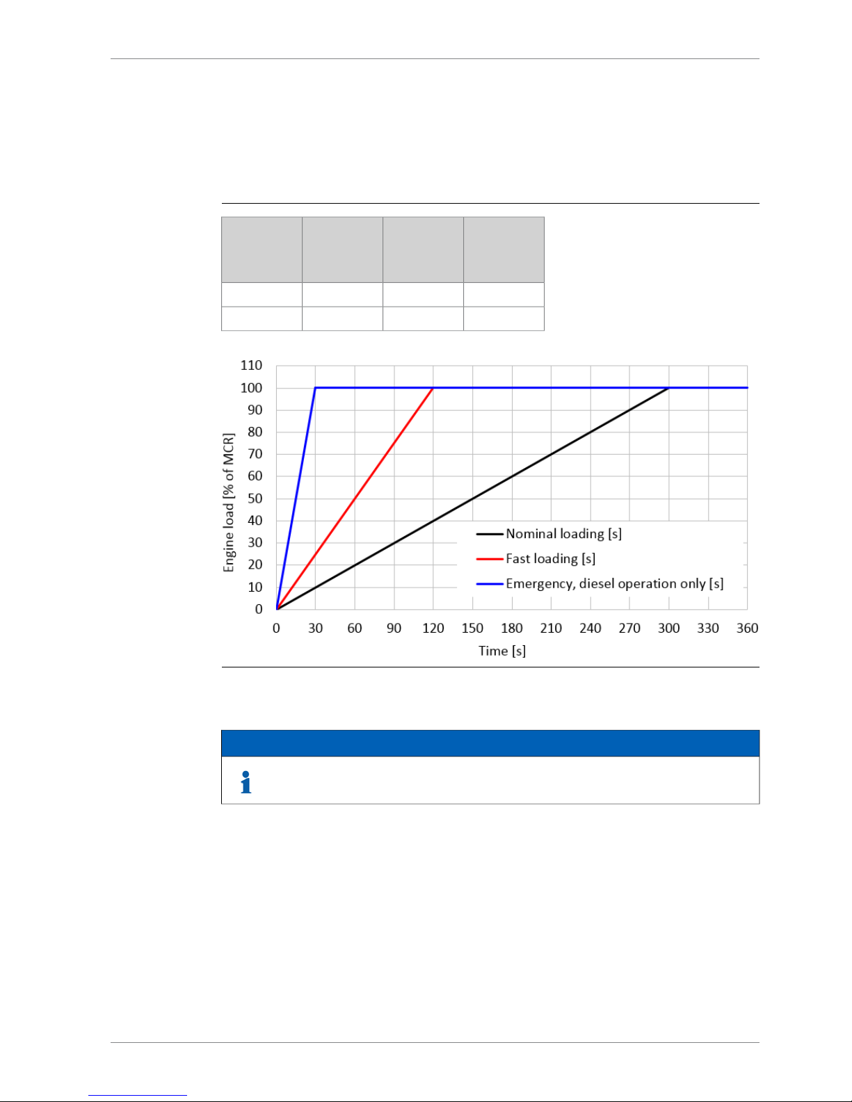
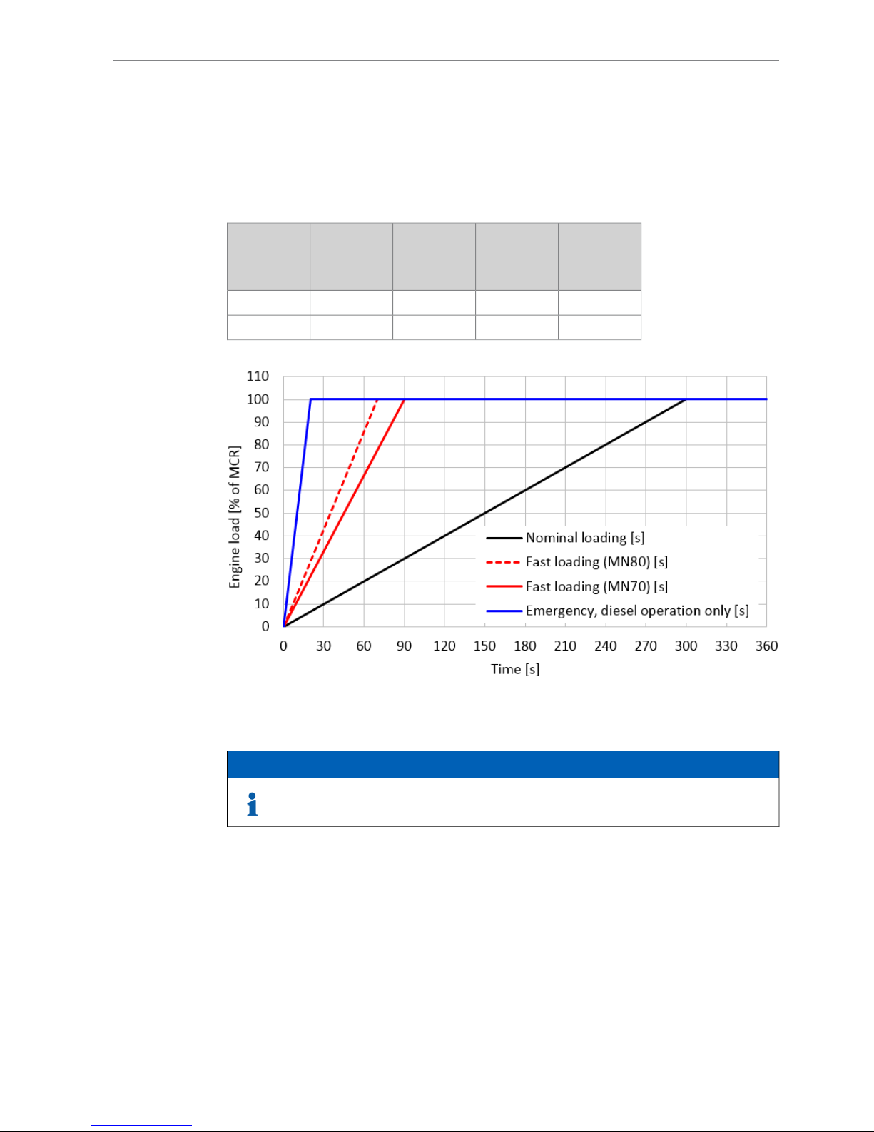
2.2.1.1 Loading Rates Variable speed engines (CPP)
Normal loading rate, variable speed engines, 750 rpm
Table 2-1 Loading rate
Emergency,
diesel operation only
[s]
Fast loading
[s]
Nominal
loading
[s]
Engine load
[% of MCR]
0000
30120300100
Fig 2-2 Normal Loading rate, variable speed engines, 750 rpm
NOTE
If normal loading rate is chosen low load running is limited to normal low load
restriction curve. Please see chapter 2.3.1.
DBAE248994 2-3
2. Operating RangesWärtsilä 31DF Product Guide
Page 18

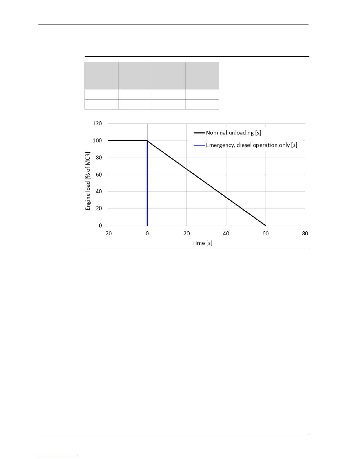
Unloading rate, variable speed engines, 750 rpm
Table 2-2 Unloading rate
Emergency,
diesel opera-
tion only
[s]
Fast loading
[s]
Nominal
loading
[s]
Engine load
[% of MCR]
0N/A
0
100
0N/A
60
0
Fig 2-3 Unloading rate, variable speed engines, 750 rpm
The propulsion control must include automatic limitation of the load increase rate. If the control
system has only one load increase ramp, then the ramp for a preheated engine should be
used. In tug applications the engines have usually reached normal operating temperature
before the tug starts assisting. The “emergency” curve is close to the maximum capability of
the engine.
Large load reductions from high load should also be performed gradually. In normal operation
the load should not be reduced from 100% to 0% in less than 15 seconds. When absolutely
necessary, the load can be reduced as fast as the pitch setting system can react (overspeed
due to windmilling must be considered for high speed ships).
2-4 DBAE248994
Wärtsilä 31DF Product Guide2. Operating Ranges
Page 19
2.2.2 Diesel electric propulsion and auxiliary engines
2.2.2.1 Loading rates Constant speed engines (DE / Aux / CPP)
Normal loading rate, constant speed engines, 720/750 rpm (DE / Aux / CPP)
Table 2-3 Normal Loading rate
Emergency,
diesel operation only
[s]
Fast loading
(MN80)
[s]
Fast loading
(MN70)
[s]
Nominal
loading
[s]
Engine load
[% of MCR]
00000
207090300100
Fig 2-4 Normal Loading rate, constant speed engines, 720/750 rpm (DE / Aux / CPP)
NOTE
If normal loading rate is chosen low load running is limited to normal low load
restriction curve. Please see chapter 2.3.1.
DBAE248994 2-5
2. Operating RangesWärtsilä 31DF Product Guide
Page 20
Unloading rate, constant speed engines, 720/750 rpm (DE / Aux / CPP)
Table 2-4 Unloading rate
Emergency,
diesel opera-
tion only
[s]
Fast loading
[s]
Nominal
loading
[s]
Engine load
[% of MCR]
0N/A
0
100
0N/A
60
0
Fig 2-5 Unloading rate, constant speed engines, 720/750 rpm (DE / Aux / CPP)
In diesel electric installations loading ramps are implemented both in the propulsion control
and in the power management system, or in the engine speed control in case isochronous
load sharing is applied. If a ramp without knee-point is used, it should not achieve 100% load
in shorter time than the ramp in the figure. When the load sharing is based on speed droop,
the load increase rate of a recently connected generator is the sum of the load transfer
performed by the power management system and the load increase performed by the
propulsion control.
The “emergency” curve is close to the maximum capability of the engine and it shall not be
used as the normal limit. In dynamic positioning applications loading ramps corresponding to
20-30 seconds from zero to full load are however normal. If the vessel has also other operating
modes, a slower loading ramp is recommended for these operating modes.
In typical auxiliary engine applications there is usually no single consumer being decisive for
the loading rate. It is recommended to group electrical equipment so that the load is increased
in small increments, and the resulting loading rate roughly corresponds to the “normal” curve.
In normal operation the load should not be reduced from 100% to 0% in less than 15 seconds.
If the application requires frequent unloading at a significantly faster rate, special arrangements
can be necessary on the engine. In an emergency situation the full load can be thrown off
instantly.
2-6 DBAE248994
Wärtsilä 31DF Product Guide2. Operating Ranges
Page 21
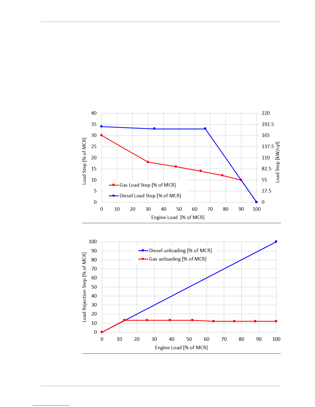
2.2.2.2 Instant Load Application
The maximum permissible load step which may be applied at any given load can be read from
the figure below. The values are valid for engines operating in island mode (speed control).
Furthermore the stated values are limited to a running engine that has reached nominal
operating temperatures, or for an engine which has been operated at above 30% load within
the last 30 minutes.
Cyclic (wave) load-taking capability can be evaluated from the figures below:
● Max instant load step = cyclic load amplitude
○ Example: With cyclic loading at average load 57% the load variation amplitude can be
14%, i.e ±7% (=50% + 14%/2)
Fig 2-6 Load Steps, CS 750 rpm
Fig 2-7 Unloading Steps, CS 750 rpm
DBAE248994 2-7
2. Operating RangesWärtsilä 31DF Product Guide
Page 22

2.3 Low load operation
2.3.1 Normal Low load operation - Normal load acceptance
In order to avoid fouling of the engine, recommended limits to the low load operation are given.
Low load operation is all loads below 20% load. Cumulative low load operation should not
exceed the recommended values given in the chart and table. The time is reset after a cleaning
run at minimum 70% load for a minimum of 1 hour.
Black line (diesel mode) limit is valid in diesel mode when intention is to continue in diesel
mode. In case the intention is to transfer to gas mode and continue operating in gas mode
then blue line (gas mode limit) is valid also for diesel mode.
The loading rates according to Normal low load load operations, chapter load performance
are allowed with these low load operation limits.
If recommended time limits are exceeded then engine shall not be loaded faster than the
nominal loading curve in the chapter loading performance.
Absolute idling time 10 minutes if the engine is to be stopped, 5 hours in gas mode or 10 hours
in diesel mode if engine is loaded afterwards.
2-8 DBAE248994
Wärtsilä 31DF Product Guide2. Operating Ranges
Page 23
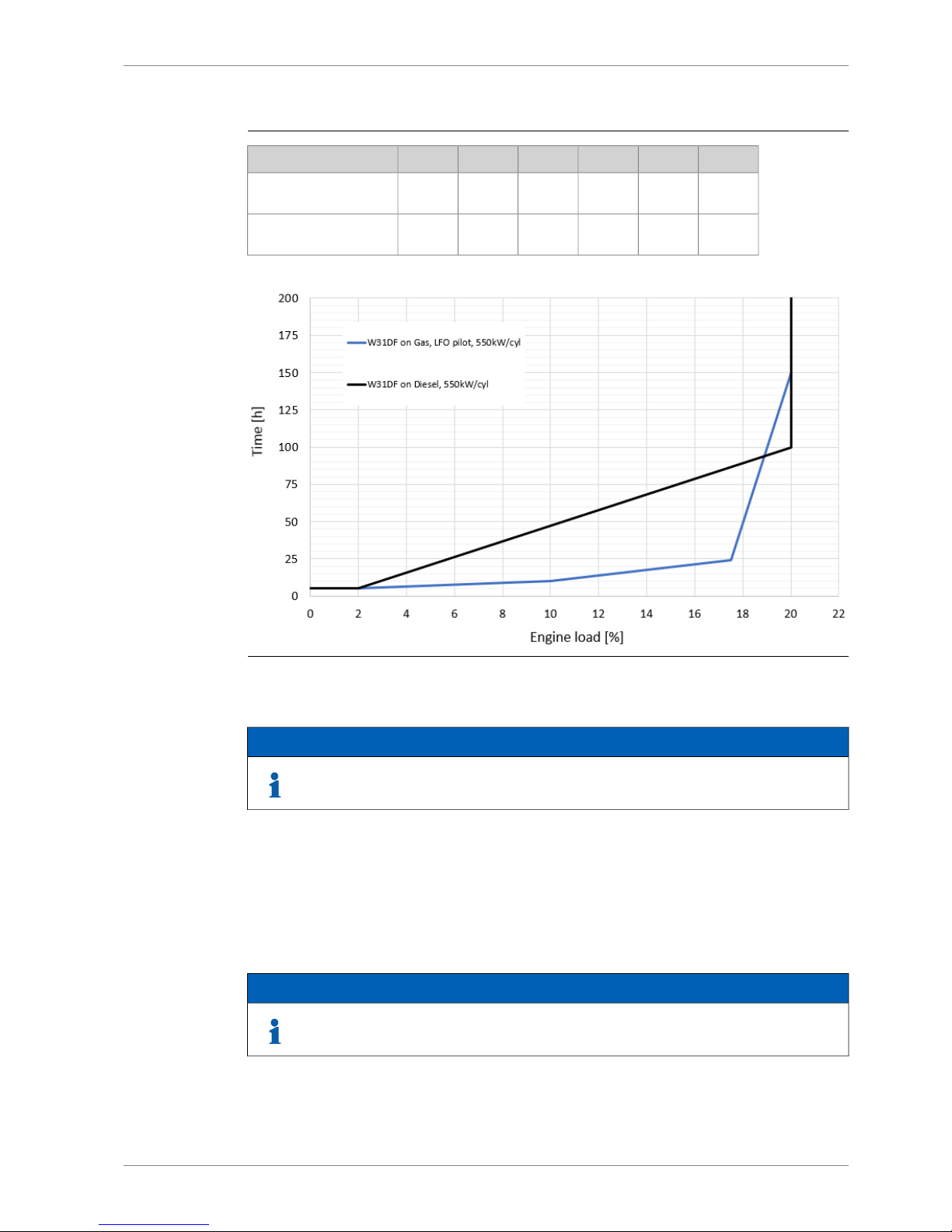
Table 2-5 Max continous low load operation time for load acceptance according to
Normal Load acceptance chapter
2017.510
20%
Load
150
241055h
W31DF on Gas, LFO pilot, 550kW/cyl
100
874755h
W31DF on Diesel,
550kW/cyl
Fig 2-8 Low load operating restrictions
NOTE
Black line is intended for diesel mode operation and blue line is intended for gas
mode operation.
2.3.2 Absolute idling
Absolute idling (declutched main engine, disconnected generator)
- Maximum 10 minutes if the engine is to be stopped after the idling. 3-5 minutes idling before
stop is recommended.
- Maximum 5 hours in gas mode and 10 hours in diesel mode if the engine is to be loaded
after the idling.
NOTE
Operating restrictions on SCR applications in low load operation to be observed.
DBAE248994 2-9
2. Operating RangesWärtsilä 31DF Product Guide
Page 24
2.4 Low air temperature
In standard conditions the following minimum inlet air temperatures apply:
Gas mode:
● Low load + 5ºC
● High load -10ºC
Diesel mode:
● Starting + 5ºC
● Idling - 5ºC
● High load - 10ºC
For further guidelines, see chapter Combustion air system design.
NOTE
Air Waste Gate (AWG) is needed when suction air temperature is below +5°C.
2-10 DBAE248994
Wärtsilä 31DF Product Guide2. Operating Ranges
Page 25
3. Technical Data
3.1 Introduction
This chapter contains technical data of the engine (heat balance, flows, pressures etc.) for
design of auxiliary systems. Further design criteria for external equipment and system layouts
are presented in the respective chapter.
3.1.1 Engine driven pumps
The fuel consumption stated in the technical data tables is with engine driven pumps. The
increase in fuel consumption with engine driven pumps is given in the table below; correction
in g/kWh (Diesel mode) and or kJ/kWh (Gas mode).
3.1.1.1 Diesel mode
Table 3-1 Constant speed engines (DE, CPP, Aux), 750/720rpm, MDF/HFO
Engine load [%]Engine driven
pumps
507585100
-2.6-1.6-1.4-1.2Lube oil
-1.0-0.7-0.6-0.5LT Water
-1.0-0.7-0.6-0.5HT Water
Table 3-2 Variable speed engines (CPP), 750rpm, MDF/HFO
Engine load [%]Engine driven
pumps
507585100
-1.4-1.4-1.3-1.4Lube oil
-0.5-0.5-0.5-0.5LT Water
-0.5-0.5-0.5-0.5HT Water
3.1.1.2 Gas mode
Table 3-3 Constant speed engines (DE, CPP, Aux), 750/720rpm, MDF/HFO
Engine load [%]Engine driven
pumps
507585100
-108.6-68.6-60.0-50.5Lube oil
-44.8-27.6-24.8-21.0LT Water
-44.8-27.6-24.8-21.0HT Water
DBAE248994 3-1
3. Technical DataWärtsilä 31DF Product Guide
Page 26

Table 3-4 Variable speed engines (CPP), 750rpm, MDF/HFO
Engine load [%]Engine driven
pumps
507585100
-58.1-57.1-57.1-57.1Lube oil
-21.0-21.0-21.0-21.0LT Water
-21.0-21.0-21.0-21.0HT Water
3-2 DBAE248994
Wärtsilä 31DF Product Guide3. Technical Data
Page 27

3.2 Wärtsilä 8V31DF
MEAUXAUXDEDE
Wärtsilä 8V31DF
Diesel
mode
Gas
mode
Diesel
mode
Gas
mode
Diesel
mode
Gas
mode
Diesel
mode
Gas
mode
Diesel
mode
Gas
mode
750750720750720rpmEngine speed
550550530550530kWCylinder output
VariableConstantConstantConstantConstantSpeed mode
44004400424044004240kWEngine output
2.712.712.722.712.72MPaMean effective pressure
Tier 2Tier 3Tier 2Tier 3Tier 2Tier 3Tier 2Tier 3Tier 2Tier 3IMO compliance
Combustion air system (Note 1)
8.46.68.46.68.16.48.46.68.16.4kg/sFlow at 100% load
4545454545°CTemperature at turbocharger in-
take, max.
60606060606060606060°CTemperature after air cooler (TE
601)
Exhaust gas system (Note 2)
8.77.48.77.48.17.18.77.48.17.1kg/sFlow at 100% load
7.46.17.46.16.95.97.46.16.95.9kg/sFlow at 85% load
6.65.56.95.46.45.26.95.46.45.2kg/sFlow at 75% load
5.03.84.93.84.63.74.93.84.63.7kg/sFlow at 50% load
270300270300270300270300270300°CTemperature after turbocharger
at 100% load (TE 517)
260320270350270350270350270350°CTemperature after turbocharger
at 85% load (TE 517)
270310260350260350260350260350°CTemperature after turbocharger
at 75% load (TE 517)
270330280370280370280370280370°CTemperature after turbocharger
at 50% load (TE 517)
77777kPaBackpressure, max.
697657697657671647697657671647mmCalculated exhaust diameter for
35 m/s
Heat balance at 100% load (Note 3)
424360424360408344424360408344kWJacket water, HT-circuit
768504768504680472768504680472kWCharge air, HT-circuit
1296106413041072120810241304107212081024kWCharge air, LT-circuit
488408488408472392488408472392kWLubricating oil, LT-circuit
120120120120120120120120120120kWRadiation
Fuel consumption (Note 4)
(Note 5)
-7280-7280-7250-7280-7250kJ/kWhTotal energy consumption at
100% load
-7230-7350-7300-7350-7300kJ/kWhTotal energy consumption at 85%
load
-7250-7500-7430-7500-7430kJ/kWhTotal energy consumption at 75%
load
-7330-7820-7790-7820-7790kJ/kWhTotal energy consumption at 50%
load
-7128-7128-7097-7128-7097kJ/kWhFuel gas consumption at 100%
load
DBAE248994 3-3
3. Technical DataWärtsilä 31DF Product Guide
Page 28

MEAUXAUXDEDE
Wärtsilä 8V31DF
Diesel
mode
Gas
mode
Diesel
mode
Gas
mode
Diesel
mode
Gas
mode
Diesel
mode
Gas
mode
Diesel
mode
Gas
mode
750750720750720rpmEngine speed
550550530550530kWCylinder output
VariableConstantConstantConstantConstantSpeed mode
-7059-7171-7121-7171-7121kJ/kWhFuel gas consumption at 85%
load
-7082-7294-7226-7294-7226kJ/kWhFuel gas consumption at 75%
load
-7157-7515-7484-7515-7484kJ/kWhFuel gas consumption at 50%
load
177.23.8177.23.8176.33.8177.23.8176.33.8g/kWhFuel oil consumption at 100%
load
172.54.2174.44.5173.14.4174.44.5173.14.4g/kWhFuel oil consumption at85% load
176.34.1177.05.1176.85.0177.05.1176.85.0g/kWhFuel oil consumption at75% load
180.44.3185.07.6184.37.6185.07.6184.37.6g/kWhFuel oil consumption 50% load
Fuel gas system
-895-895-895-895-895kPa (a)Gas pressure at engine inlet, min
(PT901)
-1015-1015-1015-1015-1015kPa (a)Gas pressure to Gas Valve Unit,
min
-0...60-0...60-0...60-0...60-0...60°CGas temperature beforeGas Valve
Unit
Fuel oil system
1000±1001000±1001000±1001000±1001000±100kPaPressure before HP pumps (PT
101)
3.63.63.63.63.6m3/hEngine driven pump capacity
(MDF only)
16...24-16...24-16...24-16...24-16...24-cStHFO viscosity before the engine
140-140-140-140-140-°CMax. HFO temperature before
engine (TE 101)
2.02.02.02.02.0cStMDF viscosity, min.
4545454545°CMax. MDF temperature before
engine (TE 101)
0.50.50.50.50.5kg/hLeak fuel quantity (HFO), clean
fuel at 100% load
1.50.91.50.91.50.91.50.91.50.9kg/hLeak fuel quantity (MDF), clean
fuel at 100% load
Lubricating oil system
420420420420420kPaPressure before bearings, nom.
(PT 201)
4040404040kPaSuction ability, including pipe
loss, max.
150150150150150kPaPriming pressure, nom. (PT 201)
3535353535kPaSuction ability priming pump, in-
cluding pipe loss, max.
7070707070°CTemperature before bearings,
nom. (TE 201)
8282828282°CTemperature after engine, approx.
144130125130125m3/hPump capacity (main), engine
driven
100100100100100m3/hPump capacity (main), electrically
driven
40.0 / 40.040.0 / 40.040.0 / 40.040.0 / 40.040.0 / 40.0m3/hPriming pump capacity (50/60Hz)
3-4 DBAE248994
Wärtsilä 31DF Product Guide3. Technical Data
Page 29
MEAUXAUXDEDE
Wärtsilä 8V31DF
Diesel
mode
Gas
mode
Diesel
mode
Gas
mode
Diesel
mode
Gas
mode
Diesel
mode
Gas
mode
Diesel
mode
Gas
mode
750750720750720rpmEngine speed
550550530550530kWCylinder output
VariableConstantConstantConstantConstantSpeed mode
2.82.82.82.82.8
m
3
Oil volume, wet sump, nom.
55555m
3
Oil volume in separate system oil
tank
0.450.350.450.350.450.350.450.350.450.35g/kWhOil consumption at 100% load,
approx.
19601960196019601960l/minCrankcase ventilation flow rate at
full load
0.10.10.10.10.1kPaCrankcase ventilation backpres-
sure, max.
6.0...6.86.0...6.86.0...6.86.0...6.86.0...6.8lOil volume in turning device
Cooling water system
HT cooling water system
358 + static358 + static358 + static358 + static358 + statickPaPressure at engine, after pump,
nom. (PT 401)
600600600600600kPaPressure at engine, after pump,
max. (PT 401)
8383838383°CTemperature before cylinders,
approx. (TE 401)
9696969696°CTemperature after engine, nom.
8080808080m3/hCapacity of engine driven pump,
nom.
210210210210210kPaPressure drop over engine, total
100100100100100
kPaPressure drop in external system,
max.
70...15070...15070...15070...15070...150kPaPressure from expansion tank
0.350.350.350.350.35m
3
Water volume in engine
365365365365365kPaDelivery head of stand-by pump
LT cooling water system
650+ static650+ static650+ static650+ static650+ statickPaPressure at engine, after pump,
nom. (PT 451)
40/ 4540/ 4540/ 4540/ 4540/ 45°CTemperature before engine, nom
(TE 451)
8080808080m3/hCapacity of engine driven pump,
nom.
110110110110110kPaPressure drop over charge air
cooler (two-stage)
100100100100100
kPaPressure drop in external system,
max.
70...15070...15070...15070...15070...150kPaPressure from expansion tank
Starting air system
30003000300030003000kPaPressure, nom.
15001500150015001500kPaPressure at engine during start,
min. (alarm) (20°C)
30003000300030003000kPaPressure, max.
15001500150015001500kPaLow pressure limit in air vessels
5.95.95.95.95.9Nm
3
Starting air consumption, start
(successful)
DBAE248994 3-5
3. Technical DataWärtsilä 31DF Product Guide
Page 30

Notes:
At ISO 15550 conditions (ambient air temperature 25°C, LT-water 25°C) and 100% load. Flow tolerance 9%.Note 1
At ISO 15550 conditions (ambient air temperature 25°C, LT-water 25°C) and 100% load. Flow tolerance 9% and temperature tolerance 10°C in gasmodeoperation. Flow tolerance 9%andtemperaturetolerance 15°C in dieselmode operation.
Note 2
At 100% output and nominal speed. The figures are valid for ambient conditions according to ISO 15550 except for LTwater temperature, which is corresponding to charge air receiver temperature 55ºC in gas operation and 60 ºC in diesel
mode. With engine driven water and lubricating oil pumps. Tolerance for cooling water heat 10%, tolerance for radiation
heat 20%. Fouling factors and a margin to be taken into account when dimensioning heat exchangers. In arctic option
all charge air coolers are in LT circuit.
Note 3
Validity of the data in diesel mode operation: at ambient conditions according to ISO 15550. Lower calorific value 42700
kJ/kg. With engine driven pumps (two cooling water + one lubricating oil pump). Tolerance 5%.
Note 4
Validity of the data in gas fuel operation: total barometric pressure, air temperature and relative humidity according to
ISO 15550:2002(E), LT water temperature corresponding to receiver temperature 55°C, pilot fuel cetane index minimum
50 according to ISO 4264. Lower calorific value 42 700 kJ/kg for pilot fuel and 49 700 kJ/kg for gas fuel. With engine
driven pumps (two cooling water pumps, one lubricating oil pump). Tolerance 5%.
Note 5
ME = Engine driving propeller, variable speed
AE = Auxiliary engine driving generator
DE = Diesel-Electric engine driving generator
Subject to revision without notice.
3-6 DBAE248994
Wärtsilä 31DF Product Guide3. Technical Data
Page 31

MEAUXAUXDEDE
Wärtsilä 8V31DF
Diesel
mode
Gas
mode
Diesel
mode
Gas
mode
Diesel
mode
Gas
mode
Diesel
mode
Gas
mode
Diesel
mode
Gas
mode
750750720750720rpmEngine speed
550550530550530kWCylinder output
VariableConstantConstantConstantConstantSpeed mode
44004400424044004240kWEngine output
2.712.712.722.712.72MPaMean effective pressure
Tier 3Tier 3Tier 3Tier 3Tier 3IMO compliance
Combustion air system (Note 1)
7.96.67.96.67.66.47.96.67.66.4kg/sFlow at 100% load
4545454545°CTemperature at turbocharger in-
take, max.
60606060606060606060°CTemperature after air cooler (TE
601)
Exhaust gas system (Note 2)
8.67.48.67.47.97.18.67.47.97.1kg/sFlow at 100% load
7.26.17.46.16.85.97.46.16.85.9kg/sFlow at 85% load
6.55.56.75.46.25.26.75.46.25.2kg/sFlow at 75% load
5.03.84.93.84.63.74.93.84.63.7kg/sFlow at 50% load
285300285300285300285300285300°CTemperature after turbocharger
at 100% load (TE 517)
285320285350285350285350285350°CTemperature after turbocharger
at 85% load (TE 517)
285310285350285350285350285350°CTemperature after turbocharger
at 75% load (TE 517)
285330285370285370285370285370°CTemperature after turbocharger
at 50% load (TE 517)
77777kPaBackpressure, max.
700657700657673647700657673647mmCalculated exhaust diameter for
35 m/s
Heat balance at 100% load (Note 3)
424360424360408344424360408344kWJacket water, HT-circuit
744504736504648472736504648472kWCharge air, HT-circuit
1280106412881072119210241288107211921024kWCharge air, LT-circuit
488408488408472392488408472392kWLubricating oil, LT-circuit
120120120120120120120120120120kWRadiation
Fuel consumption (Note 4)
(Note 5)
-7280-7280-7250-7280-7250kJ/kWhTotal energy consumption at
100% load
-7230-7350-7300-7350-7300kJ/kWhTotal energy consumption at 85%
load
-7250-7500-7430-7500-7430kJ/kWhTotal energy consumption at 75%
load
-7330-7820-7790-7820-7790kJ/kWhTotal energy consumption at 50%
load
-7128-7128-7097-7128-7097kJ/kWhFuel gas consumption at 100%
load
-7059-7171-7121-7171-7121kJ/kWhFuel gas consumption at 85%
load
DBAE248994 3-7
3. Technical DataWärtsilä 31DF Product Guide
Page 32

MEAUXAUXDEDE
Wärtsilä 8V31DF
Diesel
mode
Gas
mode
Diesel
mode
Gas
mode
Diesel
mode
Gas
mode
Diesel
mode
Gas
mode
Diesel
mode
Gas
mode
750750720750720rpmEngine speed
550550530550530kWCylinder output
VariableConstantConstantConstantConstantSpeed mode
-7082-7294-7226-7294-7226kJ/kWhFuel gas consumption at 75%
load
-7157-7515-7484-7515-7484kJ/kWhFuel gas consumption at 50%
load
177.73.8177.73.8177.23.8177.73.8177.23.8g/kWhFuel oil consumption at 100%
load
173.44.2175.04.5174.04.4175.04.5174.04.4g/kWhFuel oil consumption at85% load
177.24.1178.15.1177.85.0178.15.1177.85.0g/kWhFuel oil consumption at75% load
180.44.3185.37.6184.57.6185.37.6184.57.6g/kWhFuel oil consumption 50% load
Fuel gas system
-895-895-895-895-895kPa (a)Gas pressure at engine inlet, min
(PT901)
-1015-1015-1015-1015-1015kPa (a)Gas pressure to Gas Valve Unit,
min
-0...60-0...60-0...60-0...60-0...60°CGas temperature beforeGas Valve
Unit
Fuel oil system
1000±1001000±1001000±1001000±1001000±100kPaPressure before HP pumps (PT
101)
3.63.63.63.63.6m3/hEngine driven pump capacity
(MDF only)
16...24-16...24-16...24-16...24-16...24-cStHFO viscosity before the engine
140-140-140-140-140-°CMax. HFO temperature before
engine (TE 101)
2.02.02.02.02.0cStMDF viscosity, min.
4545454545°CMax. MDF temperature before
engine (TE 101)
0.50.50.50.50.5kg/hLeak fuel quantity (HFO), clean
fuel at 100% load
1.50.91.50.91.50.91.50.91.50.9kg/hLeak fuel quantity (MDF), clean
fuel at 100% load
Lubricating oil system
420420420420420kPaPressure before bearings, nom.
(PT 201)
4040404040kPaSuction ability, including pipe
loss, max.
150150150150150kPaPriming pressure, nom. (PT 201)
3535353535kPaSuction ability priming pump, in-
cluding pipe loss, max.
7070707070°CTemperature before bearings,
nom. (TE 201)
8282828282°CTemperature after engine, approx.
144130125130125m3/hPump capacity (main), engine
driven
100100100100100m3/hPump capacity (main), electrically
driven
40.0 / 40.040.0 / 40.040.0 / 40.040.0 / 40.040.0 / 40.0m3/hPriming pump capacity (50/60Hz)
2.82.82.82.82.8
m
3
Oil volume, wet sump, nom.
3-8 DBAE248994
Wärtsilä 31DF Product Guide3. Technical Data
Page 33

MEAUXAUXDEDE
Wärtsilä 8V31DF
Diesel
mode
Gas
mode
Diesel
mode
Gas
mode
Diesel
mode
Gas
mode
Diesel
mode
Gas
mode
Diesel
mode
Gas
mode
750750720750720rpmEngine speed
550550530550530kWCylinder output
VariableConstantConstantConstantConstantSpeed mode
55555m
3
Oil volume in separate system oil
tank
0.450.350.450.350.450.350.450.350.450.35g/kWhOil consumption at 100% load,
approx.
19601960196019601960l/minCrankcase ventilation flow rate at
full load
0.10.10.10.10.1kPaCrankcase ventilation backpres-
sure, max.
6.0...6.86.0...6.86.0...6.86.0...6.86.0...6.8lOil volume in turning device
Cooling water system
HT cooling water system
358 + static358 + static358 + static358 + static358 + statickPaPressure at engine, after pump,
nom. (PT 401)
600600600600600kPaPressure at engine, after pump,
max. (PT 401)
8383838383°CTemperature before cylinders,
approx. (TE 401)
9696969696°CTemperature after engine, nom.
8080808080m3/hCapacity of engine driven pump,
nom.
210210210210210kPaPressure drop over engine, total
100100100100100
kPaPressure drop in external system,
max.
70...15070...15070...15070...15070...150kPaPressure from expansion tank
0.350.350.350.350.35m
3
Water volume in engine
365365365365365kPaDelivery head of stand-by pump
LT cooling water system
650+ static650+ static650+ static650+ static650+ statickPaPressure at engine, after pump,
nom. (PT 451)
40/ 4540/ 4540/ 4540/ 4540/ 45°CTemperature before engine, nom
(TE 451)
8080808080m3/hCapacity of engine driven pump,
nom.
110110110110110kPaPressure drop over charge air
cooler (two-stage)
100100100100100
kPaPressure drop in external system,
max.
70...15070...15070...15070...15070...150kPaPressure from expansion tank
Starting air system
30003000300030003000kPaPressure, nom.
15001500150015001500kPaPressure at engine during start,
min. (alarm) (20°C)
30003000300030003000kPaPressure, max.
15001500150015001500kPaLow pressure limit in air vessels
5.95.95.95.95.9Nm
3
Starting air consumption, start
(successful)
Notes:
DBAE248994 3-9
3. Technical DataWärtsilä 31DF Product Guide
Page 34

At ISO 15550 conditions (ambient air temperature 25°C, LT-water 25°C) and 100% load. Flow tolerance 9%.Note 1
At ISO 15550 conditions (ambient air temperature 25°C, LT-water 25°C) and 100% load. Flow tolerance 9% and temperature tolerance 10°C in gasmodeoperation. Flow tolerance 9%andtemperaturetolerance 15°C in dieselmode operation.
Note 2
At 100% output and nominal speed. The figures are valid for ambient conditions according to ISO 15550 except for LTwater temperature, which is corresponding to charge air receiver temperature 55ºC in gas operation and 60 ºC in diesel
mode. With engine driven water and lubricating oil pumps. Tolerance for cooling water heat 10%, tolerance for radiation
heat 20%. Fouling factors and a margin to be taken into account when dimensioning heat exchangers. In arctic option
all charge air coolers are in LT circuit.
Note 3
Validity of the data in diesel mode operation: at ambient conditions according to ISO 15550. Lower calorific value 42700
kJ/kg. With engine driven pumps (two cooling water + one lubricating oil pump). Tolerance 5%.
Note 4
Validity of the data in gas fuel operation: total barometric pressure, air temperature and relative humidity according to
ISO 15550:2002(E), LT water temperature corresponding to receiver temperature 55°C, pilot fuel cetane index minimum
50 according to ISO 4264. Lower calorific value 42 700 kJ/kg for pilot fuel and 49 700 kJ/kg for gas fuel. With engine
driven pumps (two cooling water pumps, one lubricating oil pump). Tolerance 5%.
Note 5
ME = Engine driving propeller, variable speed
AE = Auxiliary engine driving generator
DE = Diesel-Electric engine driving generator
Subject to revision without notice.
3-10 DBAE248994
Wärtsilä 31DF Product Guide3. Technical Data
Page 35

3.3 Wärtsilä 10V31DF
MEAUXAUXDEDE
Wärtsilä 10V31DF
Diesel
mode
Gas
mode
Diesel
mode
Gas
mode
Diesel
mode
Gas
mode
Diesel
mode
Gas
mode
Diesel
mode
Gas
mode
750750720750720rpmEngine speed
550550530550530kWCylinder output
VariableConstantConstantConstantConstantSpeed mode
55005500530055005300kWEngine output
2.712.712.722.712.72MPaMean effective pressure
Tier 2Tier 3Tier 2Tier 3Tier 2Tier 3Tier 2Tier 3Tier 2Tier 3IMO compliance
Combustion air system (Note 1)
10.58.310.58.310.18.010.58.310.18.0kg/sFlow at 100% load
4545454545°CTemperature at turbocharger in-
take, max.
60606060606060606060°CTemperature after air cooler (TE
601)
Exhaust gas system (Note 2)
10.99.210.99.210.18.910.99.210.18.9kg/sFlow at 100% load
9.27.69.37.68.67.49.37.68.67.4kg/sFlow at 85% load
8.36.98.66.78.06.58.66.78.06.5kg/sFlow at 75% load
6.24.86.14.75.74.66.14.75.74.6kg/sFlow at 50% load
270300270300270300270300270300°CTemperature after turbocharger
at 100% load (TE 517)
260320270350270350270350270350°CTemperature after turbocharger
at 85% load (TE 517)
270310260350260350260350260350°CTemperature after turbocharger
at 75% load (TE 517)
270330280370280370280370280370°CTemperature after turbocharger
at 50% load (TE 517)
77777kPaBackpressure, max.
779735779735750723779735750723mmCalculated exhaust diameter for
35 m/s
Heat balance at 100% load (Note 3)
530450530450510430530450510430kWJacket water, HT-circuit
960630960630850590960630850590kWCharge air, HT-circuit
1620133016301340151012801630134015101280kWCharge air, LT-circuit
610510610510590490610510590490kWLubricating oil, LT-circuit
150150150150150150150150150150kWRadiation
Fuel consumption (Note 4)
(Note 5)
-7280-7280-7250-7280-7250kJ/kWhTotal energy consumption at
100% load
-7230-7350-7300-7350-7300kJ/kWhTotal energy consumption at 85%
load
-7250-7500-7430-7500-7430kJ/kWhTotal energy consumption at 75%
load
-7330-7820-7790-7820-7790kJ/kWhTotal energy consumption at 50%
load
-7128-7128-7097-7128-7097kJ/kWhFuel gas consumption at 100%
load
DBAE248994 3-11
3. Technical DataWärtsilä 31DF Product Guide
Page 36

MEAUXAUXDEDE
Wärtsilä 10V31DF
Diesel
mode
Gas
mode
Diesel
mode
Gas
mode
Diesel
mode
Gas
mode
Diesel
mode
Gas
mode
Diesel
mode
Gas
mode
750750720750720rpmEngine speed
550550530550530kWCylinder output
VariableConstantConstantConstantConstantSpeed mode
-7059-7171-7121-7171-7121kJ/kWhFuel gas consumption at 85%
load
-7082-7294-7226-7294-7226kJ/kWhFuel gas consumption at 75%
load
-7157-7515-7484-7515-7484kJ/kWhFuel gas consumption at 50%
load
177.23.8177.23.8176.33.8177.23.8176.33.8g/kWhFuel oil consumption at 100%
load
172.54.2174.44.5173.14.4174.44.5173.14.4g/kWhFuel oil consumption at85% load
176.34.1177.05.1176.85.0177.05.1176.85.0g/kWhFuel oil consumption at75% load
180.44.3185.07.6184.37.6185.07.6184.37.6g/kWhFuel oil consumption 50% load
Fuel gas system
-895-895-895-895-895kPa (a)Gas pressure at engine inlet, min
(PT901)
-1015-1015-1015-1015-1015kPa (a)Gas pressure to Gas Valve Unit,
min
-0...60-0...60-0...60-0...60-0...60°CGas temperature beforeGas Valve
Unit
Fuel oil system
1000±1001000±1001000±1001000±1001000±100kPaPressure before HP pumps (PT
101)
3.63.63.63.63.6m3/hEngine driven pump capacity
(MDF only)
16...24-16...24-16...24-16...24-16...24-cStHFO viscosity before the engine
140-140-140-140-140-°CMax. HFO temperature before
engine (TE 101)
2.02.02.02.02.0cStMDF viscosity, min.
4545454545°CMax. MDF temperature before
engine (TE 101)
0.50.50.50.50.5kg/hLeak fuel quantity (HFO), clean
fuel at 100% load
1.50.91.50.91.50.91.50.91.50.9kg/hLeak fuel quantity (MDF), clean
fuel at 100% load
Lubricating oil system
420420420420420kPaPressure before bearings, nom.
(PT 201)
4040404040kPaSuction ability, including pipe
loss, max.
150150150150150kPaPriming pressure, nom. (PT 201)
3535353535kPaSuction ability priming pump, in-
cluding pipe loss, max.
7070707070°CTemperature before bearings,
nom. (TE 201)
8282828282°CTemperature after engine, approx.
144130125130125m3/hPump capacity (main), engine
driven
120120120120120m3/hPump capacity (main), electrically
driven
50.0 / 50.050.0 / 50.050.0 / 50.050.0 / 50.050.0 / 50.0m3/hPriming pump capacity (50/60Hz)
3-12 DBAE248994
Wärtsilä 31DF Product Guide3. Technical Data
Page 37

MEAUXAUXDEDE
Wärtsilä 10V31DF
Diesel
mode
Gas
mode
Diesel
mode
Gas
mode
Diesel
mode
Gas
mode
Diesel
mode
Gas
mode
Diesel
mode
Gas
mode
750750720750720rpmEngine speed
550550530550530kWCylinder output
VariableConstantConstantConstantConstantSpeed mode
3.43.43.43.43.4
m
3
Oil volume, wet sump, nom.
66666m
3
Oil volume in separate system oil
tank
0.450.350.450.350.450.350.450.350.450.35g/kWhOil consumption at 100% load,
approx.
24502450245024502450l/minCrankcase ventilation flow rate at
full load
0.10.10.10.10.1kPaCrankcase ventilation backpres-
sure, max.
6.0...6.86.0...6.86.0...6.86.0...6.86.0...6.8lOil volume in turning device
Cooling water system
HT cooling water system
383 + static383 + static383 + static383 + static383 + statickPaPressure at engine, after pump,
nom. (PT 401)
600600600600600kPaPressure at engine, after pump,
max. (PT 401)
8383838383°CTemperature before cylinders,
approx. (TE 401)
9696969696°CTemperature after engine, nom.
9090909090m3/hCapacity of engine driven pump,
nom.
210210210210210kPaPressure drop over engine, total
100100100100100
kPaPressure drop in external system,
max.
70...15070...15070...15070...15070...150kPaPressure from expansion tank
0.40.40.40.40.4m
3
Water volume in engine
390390390390390kPaDelivery head of stand-by pump
LT cooling water system
650+ static650+ static650+ static650+ static650+ statickPaPressure at engine, after pump,
nom. (PT 451)
40/ 4540/ 4540/ 4540/ 4540/ 45°CTemperature before engine, nom
(TE 451)
9090909090m3/hCapacity of engine driven pump,
nom.
110110110110110kPaPressure drop over charge air
cooler (two-stage)
100100100100100
kPaPressure drop in external system,
max.
70...15070...15070...15070...15070...150kPaPressure from expansion tank
Starting air system
30003000300030003000kPaPressure, nom.
15001500150015001500kPaPressure at engine during start,
min. (alarm) (20°C)
30003000300030003000kPaPressure, max.
15001500150015001500kPaLow pressure limit in air vessels
6.16.16.16.16.1Nm
3
Starting air consumption, start
(successful)
DBAE248994 3-13
3. Technical DataWärtsilä 31DF Product Guide
Page 38

Notes:
At ISO 15550 conditions (ambient air temperature 25°C, LT-water 25°C) and 100% load. Flow tolerance 9%.Note 1
At ISO 15550 conditions (ambient air temperature 25°C, LT-water 25°C) and 100% load. Flow tolerance 9% and temperature tolerance 10°C in gasmodeoperation. Flow tolerance 9%andtemperaturetolerance 15°C in dieselmode operation.
Note 2
At 100% output and nominal speed. The figures are valid for ambient conditions according to ISO 15550 except for LTwater temperature, which is corresponding to charge air receiver temperature 55ºC in gas operation and 60 ºC in diesel
mode. With engine driven water and lubricating oil pumps. Tolerance for cooling water heat 10%, tolerance for radiation
heat 20%. Fouling factors and a margin to be taken into account when dimensioning heat exchangers. In arctic option
all charge air coolers are in LT circuit.
Note 3
Validity of the data in diesel mode operation: at ambient conditions according to ISO 15550. Lower calorific value 42700
kJ/kg. With engine driven pumps (two cooling water + one lubricating oil pump). Tolerance 5%.
Note 4
Validity of the data in gas fuel operation: total barometric pressure, air temperature and relative humidity according to
ISO 15550:2002(E), LT water temperature corresponding to receiver temperature 55°C, pilot fuel cetane index minimum
50 according to ISO 4264. Lower calorific value 42 700 kJ/kg for pilot fuel and 49 700 kJ/kg for gas fuel. With engine
driven pumps (two cooling water pumps, one lubricating oil pump). Tolerance 5%.
Note 5
ME = Engine driving propeller, variable speed
AE = Auxiliary engine driving generator
DE = Diesel-Electric engine driving generator
Subject to revision without notice.
3-14 DBAE248994
Wärtsilä 31DF Product Guide3. Technical Data
Page 39

MEAUXAUXDEDE
Wärtsilä 10V31DF
Diesel
mode
Gas
mode
Diesel
mode
Gas
mode
Diesel
mode
Gas
mode
Diesel
mode
Gas
mode
Diesel
mode
Gas
mode
750750720750720rpmEngine speed
550550530550530kWCylinder output
VariableConstantConstantConstantConstantSpeed mode
55005500530055005300kWEngine output
2.712.712.722.712.72MPaMean effective pressure
Tier 3Tier 3Tier 3Tier 3Tier 3IMO compliance
Combustion air system (Note 1)
9.98.39.98.39.58.09.98.39.58.0kg/sFlow at 100% load
4545454545°CTemperature at turbocharger in-
take, max.
60606060606060606060°CTemperature after air cooler (TE
601)
Exhaust gas system (Note 2)
10.79.210.79.29.98.910.79.29.98.9kg/sFlow at 100% load
9.07.69.27.68.57.49.27.68.57.4kg/sFlow at 85% load
8.16.98.46.77.86.58.46.77.86.5kg/sFlow at 75% load
6.24.86.14.75.74.66.14.75.74.6kg/sFlow at 50% load
285300285300285300285300285300°CTemperature after turbocharger
at 100% load (TE 517)
285320285350285350285350285350°CTemperature after turbocharger
at 85% load (TE 517)
285310285380285350285380285350°CTemperature after turbocharger
at 75% load (TE 517)
285330285370285370285370285370°CTemperature after turbocharger
at 50% load (TE 517)
77777kPaBackpressure, max.
782735782735752723782735752723mmCalculated exhaust diameter for
35 m/s
Heat balance at 100% load (Note 3)
530450530450510430530450510430kWJacket water, HT-circuit
930630920630810590920630810590kWCharge air, HT-circuit
1600133016101340149012801610134014901280kWCharge air, LT-circuit
610510610510590490610510590490kWLubricating oil, LT-circuit
150150150150150150150150150150kWRadiation
Fuel consumption (Note 4)
(Note 5)
-7280-7280-7250-7280-7250kJ/kWhTotal energy consumption at
100% load
-7230-7350-7300-7350-7300kJ/kWhTotal energy consumption at 85%
load
-7250-7500-7430-7500-7430kJ/kWhTotal energy consumption at 75%
load
-7330-7820-7790-7820-7790kJ/kWhTotal energy consumption at 50%
load
-7128-7128-7097-7128-7097kJ/kWhFuel gas consumption at 100%
load
-7059-7171-7121-7171-7121kJ/kWhFuel gas consumption at 85%
load
DBAE248994 3-15
3. Technical DataWärtsilä 31DF Product Guide
Page 40

MEAUXAUXDEDE
Wärtsilä 10V31DF
Diesel
mode
Gas
mode
Diesel
mode
Gas
mode
Diesel
mode
Gas
mode
Diesel
mode
Gas
mode
Diesel
mode
Gas
mode
750750720750720rpmEngine speed
550550530550530kWCylinder output
VariableConstantConstantConstantConstantSpeed mode
-7082-7294-7226-7294-7226kJ/kWhFuel gas consumption at 75%
load
-7157-7515-7484-7515-7484kJ/kWhFuel gas consumption at 50%
load
177.73.8177.73.8177.23.8177.73.8177.23.8g/kWhFuel oil consumption at 100%
load
173.44.2175.04.5174.04.4175.04.5174.04.4g/kWhFuel oil consumption at85% load
177.24.1178.15.1177.85.0178.15.1177.85.0g/kWhFuel oil consumption at75% load
180.44.3185.37.6184.57.6185.37.6184.57.6g/kWhFuel oil consumption 50% load
Fuel gas system
-895-895-895-895-895kPa (a)Gas pressure at engine inlet, min
(PT901)
-1015-1015-1015-1015-1015kPa (a)Gas pressure to Gas Valve Unit,
min
-0...60-0...60-0...60-0...60-0...60°CGas temperature beforeGas Valve
Unit
Fuel oil system
1000±1001000±1001000±1001000±1001000±100kPaPressure before HP pumps (PT
101)
3.63.63.63.63.6m3/hEngine driven pump capacity
(MDF only)
16...24-16...24-16...24-16...24-16...24-cStHFO viscosity before the engine
140-140-140-140-140-°CMax. HFO temperature before
engine (TE 101)
2.02.02.02.02.0cStMDF viscosity, min.
4545454545°CMax. MDF temperature before
engine (TE 101)
0.50.50.50.50.5kg/hLeak fuel quantity (HFO), clean
fuel at 100% load
1.50.91.50.91.50.91.50.91.50.9kg/hLeak fuel quantity (MDF), clean
fuel at 100% load
Lubricating oil system
420420420420420kPaPressure before bearings, nom.
(PT 201)
4040404040kPaSuction ability, including pipe
loss, max.
150150150150150kPaPriming pressure, nom. (PT 201)
3535353535kPaSuction ability priming pump, in-
cluding pipe loss, max.
7070707070°CTemperature before bearings,
nom. (TE 201)
8282828282°CTemperature after engine, approx.
144130125130125m3/hPump capacity (main), engine
driven
120120120120120m3/hPump capacity (main), electrically
driven
50.0 / 50.050.0 / 50.050.0 / 50.050.0 / 50.050.0 / 50.0m3/hPriming pump capacity (50/60Hz)
3.43.43.43.43.4
m
3
Oil volume, wet sump, nom.
3-16 DBAE248994
Wärtsilä 31DF Product Guide3. Technical Data
Page 41

MEAUXAUXDEDE
Wärtsilä 10V31DF
Diesel
mode
Gas
mode
Diesel
mode
Gas
mode
Diesel
mode
Gas
mode
Diesel
mode
Gas
mode
Diesel
mode
Gas
mode
750750720750720rpmEngine speed
550550530550530kWCylinder output
VariableConstantConstantConstantConstantSpeed mode
66666m
3
Oil volume in separate system oil
tank
0.450.350.450.350.450.350.450.350.450.35g/kWhOil consumption at 100% load,
approx.
24502450245024502450l/minCrankcase ventilation flow rate at
full load
0.10.10.10.10.1kPaCrankcase ventilation backpres-
sure, max.
6.0...6.86.0...6.86.0...6.86.0...6.86.0...6.8lOil volume in turning device
Cooling water system
HT cooling water system
383 + static383 + static383 + static383 + static383 + statickPaPressure at engine, after pump,
nom. (PT 401)
600600600600600kPaPressure at engine, after pump,
max. (PT 401)
8383838383°CTemperature before cylinders,
approx. (TE 401)
9696969696°CTemperature after engine, nom.
9090909090m3/hCapacity of engine driven pump,
nom.
210210210210210kPaPressure drop over engine, total
100100100100100
kPaPressure drop in external system,
max.
70...15070...15070...15070...15070...150kPaPressure from expansion tank
0.40.40.40.40.4m
3
Water volume in engine
390390390390390kPaDelivery head of stand-by pump
LT cooling water system
650+ static650+ static650+ static650+ static650+ statickPaPressure at engine, after pump,
nom. (PT 451)
40/ 4540/ 4540/ 4540/ 4540/ 45°CTemperature before engine, nom
(TE 451)
9090909090m3/hCapacity of engine driven pump,
nom.
110110110110110kPaPressure drop over charge air
cooler (two-stage)
100100100100100
kPaPressure drop in external system,
max.
70...15070...15070...15070...15070...150kPaPressure from expansion tank
Starting air system
30003000300030003000kPaPressure, nom.
15001500150015001500kPaPressure at engine during start,
min. (alarm) (20°C)
30003000300030003000kPaPressure, max.
15001500150015001500kPaLow pressure limit in air vessels
6.16.16.16.16.1Nm
3
Starting air consumption, start
(successful)
Notes:
DBAE248994 3-17
3. Technical DataWärtsilä 31DF Product Guide
Page 42

At ISO 15550 conditions (ambient air temperature 25°C, LT-water 25°C) and 100% load. Flow tolerance 9%.Note 1
At ISO 15550 conditions (ambient air temperature 25°C, LT-water 25°C) and 100% load. Flow tolerance 9% and temperature tolerance 10°C in gasmodeoperation. Flow tolerance 9%andtemperaturetolerance 15°C in dieselmode operation.
Note 2
At 100% output and nominal speed. The figures are valid for ambient conditions according to ISO 15550 except for LTwater temperature, which is corresponding to charge air receiver temperature 55ºC in gas operation and 60 ºC in diesel
mode. With engine driven water and lubricating oil pumps. Tolerance for cooling water heat 10%, tolerance for radiation
heat 20%. Fouling factors and a margin to be taken into account when dimensioning heat exchangers. In arctic option
all charge air coolers are in LT circuit.
Note 3
Validity of the data in diesel mode operation: at ambient conditions according to ISO 15550. Lower calorific value 42700
kJ/kg. With engine driven pumps (two cooling water + one lubricating oil pump). Tolerance 5%.
Note 4
Validity of the data in gas fuel operation: total barometric pressure, air temperature and relative humidity according to
ISO 15550:2002(E), LT water temperature corresponding to receiver temperature 55°C, pilot fuel cetane index minimum
50 according to ISO 4264. Lower calorific value 42 700 kJ/kg for pilot fuel and 49 700 kJ/kg for gas fuel. With engine
driven pumps (two cooling water pumps, one lubricating oil pump). Tolerance 5%.
Note 5
ME = Engine driving propeller, variable speed
AE = Auxiliary engine driving generator
DE = Diesel-Electric engine driving generator
Subject to revision without notice.
3-18 DBAE248994
Wärtsilä 31DF Product Guide3. Technical Data
Page 43

3.4 Wärtsilä 12V31DF
MEAUXAUXDEDE
Wärtsilä 12V31DF
Diesel
mode
Gas
mode
Diesel
mode
Gas
mode
Diesel
mode
Gas
mode
Diesel
mode
Gas
mode
Diesel
mode
Gas
mode
750750720750720rpmEngine speed
550550530550530kWCylinder output
VariableConstantConstantConstantConstantSpeed mode
66006600636066006360kWEngine output
2.712.712.722.712.72MPaMean effective pressure
Tier 2Tier 3Tier 2Tier 3Tier 2Tier 3Tier 2Tier 3Tier 2Tier 3IMO compliance
Combustion air system (Note 1)
12.69.912.69.912.29.612.69.912.29.6kg/sFlow at 100% load
4545454545°CTemperature at turbocharger in-
take, max.
60606060606060606060°CTemperature after air cooler (TE
601)
Exhaust gas system (Note 2)
13.111.013.111.012.110.713.111.012.110.7kg/sFlow at 100% load
11.09.111.29.110.38.911.29.110.38.9kg/sFlow at 85% load
10.08.310.38.09.67.810.38.09.67.8kg/sFlow at 75% load
7.45.87.35.66.85.57.35.66.85.5kg/sFlow at 50% load
270300270300270300270300270300°CTemperature after turbocharger
at 100% load (TE 517)
260320270350270350270350270350°CTemperature after turbocharger
at 85% load (TE 517)
270310260350260350260350260350°CTemperature after turbocharger
at 75% load (TE 517)
270330280370280370280370280370°CTemperature after turbocharger
at 50% load (TE 517)
77777kPaBackpressure, max.
853805853805821792853805821792mmCalculated exhaust diameter for
35 m/s
Heat balance at 100% load (Note 3)
636540636540612516636540612516kWJacket water, HT-circuit
11527561152756102070811527561020708kWCharge air, HT-circuit
1944159619561608181215361956160818121536kWCharge air, LT-circuit
732612732612708588732612708588kWLubricating oil, LT-circuit
180180180180180180180180180180kWRadiation
Fuel consumption (Note 4)
(Note 5)
-7280-7280-7250-7280-7250kJ/kWhTotal energy consumption at
100% load
-7230-7350-7300-7350-7300kJ/kWhTotal energy consumption at 85%
load
-7250-7500-7430-7500-7430kJ/kWhTotal energy consumption at 75%
load
-7330-7820-7790-7820-7790kJ/kWhTotal energy consumption at 50%
load
-7128-7128-7097-7128-7097kJ/kWhFuel gas consumption at 100%
load
DBAE248994 3-19
3. Technical DataWärtsilä 31DF Product Guide
Page 44

MEAUXAUXDEDE
Wärtsilä 12V31DF
Diesel
mode
Gas
mode
Diesel
mode
Gas
mode
Diesel
mode
Gas
mode
Diesel
mode
Gas
mode
Diesel
mode
Gas
mode
750750720750720rpmEngine speed
550550530550530kWCylinder output
VariableConstantConstantConstantConstantSpeed mode
-7059-7171-7121-7171-7121kJ/kWhFuel gas consumption at 85%
load
-7082-7294-7226-7294-7226kJ/kWhFuel gas consumption at 75%
load
-7157-7515-7484-7515-7484kJ/kWhFuel gas consumption at 50%
load
177.23.8177.23.8176.33.8177.23.8176.33.8g/kWhFuel oil consumption at 100%
load
172.54.2174.44.5173.14.4174.44.5173.14.4g/kWhFuel oil consumption at85% load
176.34.1177.05.1176.85.0177.05.1176.85.0g/kWhFuel oil consumption at75% load
180.44.3185.07.6184.37.6185.07.6184.37.6g/kWhFuel oil consumption 50% load
Fuel gas system
-895-895-895-895-895kPa (a)Gas pressure at engine inlet, min
(PT901)
-1015-1015-1015-1015-1015kPa (a)Gas pressure to Gas Valve Unit,
min
-0...60-0...60-0...60-0...60-0...60°CGas temperature beforeGas Valve
Unit
Fuel oil system
1000±1001000±1001000±1001000±1001000±100kPaPressure before HP pumps (PT
101)
7.27.27.27.27.2m3/hEngine driven pump capacity
(MDF only)
16...24-16...24-16...24-16...24-16...24-cStHFO viscosity before the engine
140-140-140-140-140-°CMax. HFO temperature before
engine (TE 101)
2.02.02.02.02.0cStMDF viscosity, min.
4545454545°CMax. MDF temperature before
engine (TE 101)
1.11.11.11.11.1kg/hLeak fuel quantity (HFO), clean
fuel at 100% load
3.01.83.01.83.01.83.01.83.01.8kg/hLeak fuel quantity (MDF), clean
fuel at 100% load
Lubricating oil system
420420420420420kPaPressure before bearings, nom.
(PT 201)
4040404040kPaSuction ability, including pipe
loss, max.
150150150150150kPaPriming pressure, nom. (PT 201)
3535353535kPaSuction ability priming pump, in-
cluding pipe loss, max.
7070707070°CTemperature before bearings,
nom. (TE 201)
8282828282°CTemperature after engine, approx.
170144138144138m3/hPump capacity (main), engine
driven
137137137137137m3/hPump capacity (main), electrically
driven
60.0 / 60.060.0 / 60.060.0 / 60.060.0 / 60.060.0 / 60.0m3/hPriming pump capacity (50/60Hz)
3-20 DBAE248994
Wärtsilä 31DF Product Guide3. Technical Data
Page 45

MEAUXAUXDEDE
Wärtsilä 12V31DF
Diesel
mode
Gas
mode
Diesel
mode
Gas
mode
Diesel
mode
Gas
mode
Diesel
mode
Gas
mode
Diesel
mode
Gas
mode
750750720750720rpmEngine speed
550550530550530kWCylinder output
VariableConstantConstantConstantConstantSpeed mode
4.24.24.24.24.2
m
3
Oil volume, wet sump, nom.
00000m
3
Oil volume in separate system oil
tank
0.450.350.450.350.450.350.450.350.450.35g/kWhOil consumption at 100% load,
approx.
29402940294029402940l/minCrankcase ventilation flow rate at
full load
0.10.10.10.10.1kPaCrankcase ventilation backpres-
sure, max.
6.0...6.86.0...6.86.0...6.86.0...6.86.0...6.8lOil volume in turning device
Cooling water system
HT cooling water system
363 + static363 + static363 + static363 + static363 + statickPaPressure at engine, after pump,
nom. (PT 401)
600600600600600kPaPressure at engine, after pump,
max. (PT 401)
8383838383°CTemperature before cylinders,
approx. (TE 401)
9696969696°CTemperature after engine, nom.
110110110110110m3/hCapacity of engine driven pump,
nom.
210210210210210kPaPressure drop over engine, total
100100100100100
kPaPressure drop in external system,
max.
70...15070...15070...15070...15070...150kPaPressure from expansion tank
0.550.550.550.550.55m
3
Water volume in engine
370370370370370kPaDelivery head of stand-by pump
LT cooling water system
650+ static650+ static650+ static650+ static650+ statickPaPressure at engine, after pump,
nom. (PT 451)
40/ 4540/ 4540/ 4540/ 4540/ 45°CTemperature before engine, nom
(TE 451)
110110110110110m3/hCapacity of engine driven pump,
nom.
110110110110110kPaPressure drop over charge air
cooler (two-stage)
100100100100100
kPaPressure drop in external system,
max.
70...15070...15070...15070...15070...150kPaPressure from expansion tank
Starting air system
30003000300030003000kPaPressure, nom.
15001500150015001500kPaPressure at engine during start,
min. (alarm) (20°C)
30003000300030003000kPaPressure, max.
15001500150015001500kPaLow pressure limit in air vessels
6.46.46.46.46.4Nm
3
Starting air consumption, start
(successful)
DBAE248994 3-21
3. Technical DataWärtsilä 31DF Product Guide
Page 46

Notes:
At ISO 15550 conditions (ambient air temperature 25°C, LT-water 25°C) and 100% load. Flow tolerance 9%.Note 1
At ISO 15550 conditions (ambient air temperature 25°C, LT-water 25°C) and 100% load. Flow tolerance 9% and temperature tolerance 10°C in gasmodeoperation. Flow tolerance 9%andtemperaturetolerance 15°C in dieselmode operation.
Note 2
At 100% output and nominal speed. The figures are valid for ambient conditions according to ISO 15550 except for LTwater temperature, which is corresponding to charge air receiver temperature 55ºC in gas operation and 60 ºC in diesel
mode. With engine driven water and lubricating oil pumps. Tolerance for cooling water heat 10%, tolerance for radiation
heat 20%. Fouling factors and a margin to be taken into account when dimensioning heat exchangers. In arctic option
all charge air coolers are in LT circuit.
Note 3
Validity of the data in diesel mode operation: at ambient conditions according to ISO 15550. Lower calorific value 42700
kJ/kg. With engine driven pumps (two cooling water + one lubricating oil pump). Tolerance 5%.
Note 4
Validity of the data in gas fuel operation: total barometric pressure, air temperature and relative humidity according to
ISO 15550:2002(E), LT water temperature corresponding to receiver temperature 55°C, pilot fuel cetane index minimum
50 according to ISO 4264. Lower calorific value 42 700 kJ/kg for pilot fuel and 49 700 kJ/kg for gas fuel. With engine
driven pumps (two cooling water pumps, one lubricating oil pump). Tolerance 5%.
Note 5
ME = Engine driving propeller, variable speed
AE = Auxiliary engine driving generator
DE = Diesel-Electric engine driving generator
Subject to revision without notice.
3-22 DBAE248994
Wärtsilä 31DF Product Guide3. Technical Data
Page 47

MEAUXAUXDEDE
Wärtsilä 12V31DF
Diesel
mode
Gas
mode
Diesel
mode
Gas
mode
Diesel
mode
Gas
mode
Diesel
mode
Gas
mode
Diesel
mode
Gas
mode
750750720750720rpmEngine speed
550550530550530kWCylinder output
VariableConstantConstantConstantConstantSpeed mode
66006600636066006360kWEngine output
2.712.712.722.712.72MPaMean effective pressure
Tier 3Tier 3Tier 3Tier 3Tier 3IMO compliance
Combustion air system (Note 1)
11.99.911.99.911.49.611.99.911.49.6kg/sFlow at 100% load
4545454545°CTemperature at turbocharger in-
take, max.
60606060606060606060°CTemperature after air cooler (TE
601)
Exhaust gas system (Note 2)
12.811.012.811.011.910.712.811.011.910.7kg/sFlow at 100% load
10.89.111.09.110.28.911.09.110.28.9kg/sFlow at 85% load
9.78.310.18.09.47.810.18.09.47.8kg/sFlow at 75% load
7.45.87.35.66.85.57.35.66.85.5kg/sFlow at 50% load
285300285300285300285300285300°CTemperature after turbocharger
at 100% load (TE 517)
285320285350285350285350285350°CTemperature after turbocharger
at 85% load (TE 517)
285310285350285350285350285350°CTemperature after turbocharger
at 75% load (TE 517)
285330285370285370285370285370°CTemperature after turbocharger
at 50% load (TE 517)
77777kPaBackpressure, max.
857805857805824792857805824792mmCalculated exhaust diameter for
35 m/s
Heat balance at 100% load (Note 3)
636540636540612516636540612516kWJacket water, HT-circuit
111675611047569727081104756972708kWCharge air, HT-circuit
1920159619321608178815361932160817881536kWCharge air, LT-circuit
732612732612708588732612708588kWLubricating oil, LT-circuit
180180180180180180180180180180kWRadiation
Fuel consumption (Note 4)
(Note 5)
-7280-7280-7250-7280-7250kJ/kWhTotal energy consumption at
100% load
-7230-7350-7300-7350-7300kJ/kWhTotal energy consumption at 85%
load
-7250-7500-7430-7500-7430kJ/kWhTotal energy consumption at 75%
load
-7330-7820-7790-7820-7790kJ/kWhTotal energy consumption at 50%
load
-7128-7128-7097-7128-7097kJ/kWhFuel gas consumption at 100%
load
-7059-7171-7121-7171-7121kJ/kWhFuel gas consumption at 85%
load
DBAE248994 3-23
3. Technical DataWärtsilä 31DF Product Guide
Page 48

MEAUXAUXDEDE
Wärtsilä 12V31DF
Diesel
mode
Gas
mode
Diesel
mode
Gas
mode
Diesel
mode
Gas
mode
Diesel
mode
Gas
mode
Diesel
mode
Gas
mode
750750720750720rpmEngine speed
550550530550530kWCylinder output
VariableConstantConstantConstantConstantSpeed mode
-7082-7294-7226-7294-7226kJ/kWhFuel gas consumption at 75%
load
-7157-7515-7484-7515-7484kJ/kWhFuel gas consumption at 50%
load
177.73.8177.73.8177.23.8177.73.8177.23.8g/kWhFuel oil consumption at 100%
load
173.44.2175.04.5174.04.4175.04.5174.04.4g/kWhFuel oil consumption at85% load
177.24.1178.15.1177.85.0178.15.1177.85.0g/kWhFuel oil consumption at75% load
180.44.3185.37.6184.57.6185.37.6184.57.6g/kWhFuel oil consumption 50% load
Fuel gas system
-895-895-895-895-895kPa (a)Gas pressure at engine inlet, min
(PT901)
-1015-1015-1015-1015-1015kPa (a)Gas pressure to Gas Valve Unit,
min
-0...60-0...60-0...60-0...60-0...60°CGas temperature beforeGas Valve
Unit
Fuel oil system
1000±1001000±1001000±1001000±1001000±100kPaPressure before HP pumps (PT
101)
7.27.27.27.27.2m3/hEngine driven pump capacity
(MDF only)
16...24-16...24-16...24-16...24-16...24-cStHFO viscosity before the engine
140-140-140-140-140-°CMax. HFO temperature before
engine (TE 101)
2.02.02.02.02.0cStMDF viscosity, min.
4545454545°CMax. MDF temperature before
engine (TE 101)
1.11.11.11.11.1kg/hLeak fuel quantity (HFO), clean
fuel at 100% load
3.01.83.01.83.01.83.01.83.01.8kg/hLeak fuel quantity (MDF), clean
fuel at 100% load
Lubricating oil system
420420420420420kPaPressure before bearings, nom.
(PT 201)
4040404040kPaSuction ability, including pipe
loss, max.
150150150150150kPaPriming pressure, nom. (PT 201)
3535353535kPaSuction ability priming pump, in-
cluding pipe loss, max.
7070707070°CTemperature before bearings,
nom. (TE 201)
8282828282°CTemperature after engine, approx.
170144138144138m3/hPump capacity (main), engine
driven
137137137137137m3/hPump capacity (main), electrically
driven
60.0 / 60.060.0 / 60.060.0 / 60.060.0 / 60.060.0 / 60.0m3/hPriming pump capacity (50/60Hz)
4.24.24.24.24.2
m
3
Oil volume, wet sump, nom.
3-24 DBAE248994
Wärtsilä 31DF Product Guide3. Technical Data
Page 49

MEAUXAUXDEDE
Wärtsilä 12V31DF
Diesel
mode
Gas
mode
Diesel
mode
Gas
mode
Diesel
mode
Gas
mode
Diesel
mode
Gas
mode
Diesel
mode
Gas
mode
750750720750720rpmEngine speed
550550530550530kWCylinder output
VariableConstantConstantConstantConstantSpeed mode
00000m
3
Oil volume in separate system oil
tank
0.450.350.450.350.450.350.450.350.450.35g/kWhOil consumption at 100% load,
approx.
29402940294029402940l/minCrankcase ventilation flow rate at
full load
0.10.10.10.10.1kPaCrankcase ventilation backpres-
sure, max.
6.0...6.86.0...6.86.0...6.86.0...6.86.0...6.8lOil volume in turning device
Cooling water system
HT cooling water system
363 + static363 + static363 + static363 + static363 + statickPaPressure at engine, after pump,
nom. (PT 401)
600600600600600kPaPressure at engine, after pump,
max. (PT 401)
8383838383°CTemperature before cylinders,
approx. (TE 401)
9696969696°CTemperature after engine, nom.
110110110110110m3/hCapacity of engine driven pump,
nom.
210210210210210kPaPressure drop over engine, total
100100100100100
kPaPressure drop in external system,
max.
70...15070...15070...15070...15070...150kPaPressure from expansion tank
0.550.550.550.550.55m
3
Water volume in engine
370370370370370kPaDelivery head of stand-by pump
LT cooling water system
650+ static650+ static650+ static650+ static650+ statickPaPressure at engine, after pump,
nom. (PT 451)
40/ 4540/ 4540/ 4540/ 4540/ 45°CTemperature before engine, nom
(TE 451)
110110110110110m3/hCapacity of engine driven pump,
nom.
110110110110110kPaPressure drop over charge air
cooler (two-stage)
100100100100100
kPaPressure drop in external system,
max.
70...15070...15070...15070...15070...150kPaPressure from expansion tank
Starting air system
30003000300030003000kPaPressure, nom.
15001500150015001500kPaPressure at engine during start,
min. (alarm) (20°C)
30003000300030003000kPaPressure, max.
15001500150015001500kPaLow pressure limit in air vessels
6.46.46.46.46.4Nm
3
Starting air consumption, start
(successful)
Notes:
DBAE248994 3-25
3. Technical DataWärtsilä 31DF Product Guide
Page 50

At ISO 15550 conditions (ambient air temperature 25°C, LT-water 25°C) and 100% load. Flow tolerance 9%.Note 1
At ISO 15550 conditions (ambient air temperature 25°C, LT-water 25°C) and 100% load. Flow tolerance 9% and temperature tolerance 10°C in gasmodeoperation. Flow tolerance 9%andtemperaturetolerance 15°C in dieselmode operation.
Note 2
At 100% output and nominal speed. The figures are valid for ambient conditions according to ISO 15550 except for LTwater temperature, which is corresponding to charge air receiver temperature 55ºC in gas operation and 60 ºC in diesel
mode. With engine driven water and lubricating oil pumps. Tolerance for cooling water heat 10%, tolerance for radiation
heat 20%. Fouling factors and a margin to be taken into account when dimensioning heat exchangers. In arctic option
all charge air coolers are in LT circuit.
Note 3
Validity of the data in diesel mode operation: at ambient conditions according to ISO 15550. Lower calorific value 42700
kJ/kg. With engine driven pumps (two cooling water + one lubricating oil pump). Tolerance 5%.
Note 4
Validity of the data in gas fuel operation: total barometric pressure, air temperature and relative humidity according to
ISO 15550:2002(E), LT water temperature corresponding to receiver temperature 55°C, pilot fuel cetane index minimum
50 according to ISO 4264. Lower calorific value 42 700 kJ/kg for pilot fuel and 49 700 kJ/kg for gas fuel. With engine
driven pumps (two cooling water pumps, one lubricating oil pump). Tolerance 5%.
Note 5
ME = Engine driving propeller, variable speed
AE = Auxiliary engine driving generator
DE = Diesel-Electric engine driving generator
Subject to revision without notice.
3-26 DBAE248994
Wärtsilä 31DF Product Guide3. Technical Data
Page 51

3.5 Wärtsilä 14V31DF
MEAUXAUXDEDE
Wärtsilä 14V31DF
Diesel
mode
Gas
mode
Diesel
mode
Gas
mode
Diesel
mode
Gas
mode
Diesel
mode
Gas
mode
Diesel
mode
Gas
mode
750750720750720rpmEngine speed
550550530550530kWCylinder output
VariableConstantConstantConstantConstantSpeed mode
77007700742077007420kWEngine output
2.712.712.722.712.72MPaMean effective pressure
Tier 2Tier 3Tier 2Tier 3Tier 2Tier 3Tier 2Tier 3Tier 2Tier 3IMO compliance
Combustion air system (Note 1)
14.711.614.711.614.211.214.711.614.211.2kg/sFlow at 100% load
4545454545°CTemperature at turbocharger in-
take, max.
60606060606060606060°CTemperature after air cooler (TE
601)
Exhaust gas system (Note 2)
15.312.915.312.914.112.515.312.914.112.5kg/sFlow at 100% load
12.910.613.010.612.010.413.010.612.010.4kg/sFlow at 85% load
11.69.712.09.411.29.112.09.411.29.1kg/sFlow at 75% load
8.76.78.56.68.06.48.56.68.06.4kg/sFlow at 50% load
270300270300270300270300270300°CTemperature after turbocharger
at 100% load (TE 517)
260320270350270350270350270350°CTemperature after turbocharger
at 85% load (TE 517)
270310260350260350260350260350°CTemperature after turbocharger
at 75% load (TE 517)
270330280370280370280370280370°CTemperature after turbocharger
at 50% load (TE 517)
77777kPaBackpressure, max.
921870921870887855921870887855mmCalculated exhaust diameter for
35 m/s
Heat balance at 100% load (Note 3)
742630742630714602742630714602kWJacket water, HT-circuit
13448821344882119082613448821190826kWCharge air, HT-circuit
2268186222821876211417922282187621141792kWCharge air, LT-circuit
854714854714826686854714826686kWLubricating oil, LT-circuit
210210210210210210210210210210kWRadiation
Fuel consumption (Note 4)
(Note 5)
-7280-7280-7250-7280-7250kJ/kWhTotal energy consumption at
100% load
-7230-7350-7300-7350-7300kJ/kWhTotal energy consumption at 85%
load
-7250-7500-7430-7500-7430kJ/kWhTotal energy consumption at 75%
load
-7330-7820-7790-7820-7790kJ/kWhTotal energy consumption at 50%
load
-7128-7128-7097-7128-7097kJ/kWhFuel gas consumption at 100%
load
DBAE248994 3-27
3. Technical DataWärtsilä 31DF Product Guide
Page 52

MEAUXAUXDEDE
Wärtsilä 14V31DF
Diesel
mode
Gas
mode
Diesel
mode
Gas
mode
Diesel
mode
Gas
mode
Diesel
mode
Gas
mode
Diesel
mode
Gas
mode
750750720750720rpmEngine speed
550550530550530kWCylinder output
VariableConstantConstantConstantConstantSpeed mode
-7059-7171-7121-7171-7121kJ/kWhFuel gas consumption at 85%
load
-7082-7294-7226-7294-7226kJ/kWhFuel gas consumption at 75%
load
-7157-7515-7484-7515-7484kJ/kWhFuel gas consumption at 50%
load
177.23.8177.23.8176.33.8177.23.8176.33.8g/kWhFuel oil consumption at 100%
load
172.54.2174.44.5173.14.4174.44.5173.14.4g/kWhFuel oil consumption at85% load
176.34.1177.05.1176.85.0177.05.1176.85.0g/kWhFuel oil consumption at75% load
180.44.3185.07.6184.37.6185.07.6184.37.6g/kWhFuel oil consumption 50% load
Fuel gas system
-895-895-895-895-895kPa (a)Gas pressure at engine inlet, min
(PT901)
-1015-1015-1015-1015-1015kPa (a)Gas pressure to Gas Valve Unit,
min
-0...60-0...60-0...60-0...60-0...60°CGas temperature beforeGas Valve
Unit
Fuel oil system
1000±1001000±1001000±1001000±1001000±100kPaPressure before HP pumps (PT
101)
7.27.27.27.27.2m3/hEngine driven pump capacity
(MDF only)
16...24-16...24-16...24-16...24-16...24-cStHFO viscosity before the engine
140-140-140-140-140-°CMax. HFO temperature before
engine (TE 101)
2.02.02.02.02.0cStMDF viscosity, min.
4545454545°CMax. MDF temperature before
engine (TE 101)
1.11.11.11.11.1kg/hLeak fuel quantity (HFO), clean
fuel at 100% load
3.01.83.01.83.01.83.01.83.01.8kg/hLeak fuel quantity (MDF), clean
fuel at 100% load
Lubricating oil system
420420420420420kPaPressure before bearings, nom.
(PT 201)
4040404040kPaSuction ability, including pipe
loss, max.
150150150150150kPaPriming pressure, nom. (PT 201)
3535353535kPaSuction ability priming pump, in-
cluding pipe loss, max.
7070707070°CTemperature before bearings,
nom. (TE 201)
8282828282°CTemperature after engine, approx.
189170164170164m3/hPump capacity (main), engine
driven
160160160160160m3/hPump capacity (main), electrically
driven
70.0 / 70.070.0 / 70.070.0 / 70.070.0 / 70.070.0 / 70.0m3/hPriming pump capacity (50/60Hz)
3-28 DBAE248994
Wärtsilä 31DF Product Guide3. Technical Data
Page 53

MEAUXAUXDEDE
Wärtsilä 14V31DF
Diesel
mode
Gas
mode
Diesel
mode
Gas
mode
Diesel
mode
Gas
mode
Diesel
mode
Gas
mode
Diesel
mode
Gas
mode
750750720750720rpmEngine speed
550550530550530kWCylinder output
VariableConstantConstantConstantConstantSpeed mode
4.84.84.84.84.8
m
3
Oil volume, wet sump, nom.
00000m
3
Oil volume in separate system oil
tank
0.450.350.450.350.450.350.450.350.450.35g/kWhOil consumption at 100% load,
approx.
34303430343034303430l/minCrankcase ventilation flow rate at
full load
0.10.10.10.10.1kPaCrankcase ventilation backpres-
sure, max.
6.0...6.86.0...6.86.0...6.86.0...6.86.0...6.8lOil volume in turning device
Cooling water system
HT cooling water system
398 + static398 + static398 + static398 + static398 + statickPaPressure at engine, after pump,
nom. (PT 401)
600600600600600kPaPressure at engine, after pump,
max. (PT 401)
8383838383°CTemperature before cylinders,
approx. (TE 401)
9696969696°CTemperature after engine, nom.
130130130130130m3/hCapacity of engine driven pump,
nom.
210210210210210kPaPressure drop over engine, total
100100100100100
kPaPressure drop in external system,
max.
70...15070...15070...15070...15070...150kPaPressure from expansion tank
0.60.60.60.60.6m
3
Water volume in engine
405405405405405kPaDelivery head of stand-by pump
LT cooling water system
650+ static650+ static650+ static650+ static650+ statickPaPressure at engine, after pump,
nom. (PT 451)
40/ 4540/ 4540/ 4540/ 4540/ 45°CTemperature before engine, nom
(TE 451)
130130130130130m3/hCapacity of engine driven pump,
nom.
110110110110110kPaPressure drop over charge air
cooler (two-stage)
100100100100100
kPaPressure drop in external system,
max.
70...15070...15070...15070...15070...150kPaPressure from expansion tank
Starting air system
30003000300030003000kPaPressure, nom.
15001500150015001500kPaPressure at engine during start,
min. (alarm) (20°C)
30003000300030003000kPaPressure, max.
15001500150015001500kPaLow pressure limit in air vessels
6.86.86.86.86.8Nm
3
Starting air consumption, start
(successful)
DBAE248994 3-29
3. Technical DataWärtsilä 31DF Product Guide
Page 54

Notes:
At ISO 15550 conditions (ambient air temperature 25°C, LT-water 25°C) and 100% load. Flow tolerance 9%.Note 1
At ISO 15550 conditions (ambient air temperature 25°C, LT-water 25°C) and 100% load. Flow tolerance 9% and temperature tolerance 10°C in gasmodeoperation. Flow tolerance 9%andtemperaturetolerance 15°C in dieselmode operation.
Note 2
At 100% output and nominal speed. The figures are valid for ambient conditions according to ISO 15550 except for LTwater temperature, which is corresponding to charge air receiver temperature 55ºC in gas operation and 60 ºC in diesel
mode. With engine driven water and lubricating oil pumps. Tolerance for cooling water heat 10%, tolerance for radiation
heat 20%. Fouling factors and a margin to be taken into account when dimensioning heat exchangers. In arctic option
all charge air coolers are in LT circuit.
Note 3
Validity of the data in diesel mode operation: at ambient conditions according to ISO 15550. Lower calorific value 42700
kJ/kg. With engine driven pumps (two cooling water + one lubricating oil pump). Tolerance 5%.
Note 4
Validity of the data in gas fuel operation: total barometric pressure, air temperature and relative humidity according to
ISO 15550:2002(E), LT water temperature corresponding to receiver temperature 55°C, pilot fuel cetane index minimum
50 according to ISO 4264. Lower calorific value 42 700 kJ/kg for pilot fuel and 49 700 kJ/kg for gas fuel. With engine
driven pumps (two cooling water pumps, one lubricating oil pump). Tolerance 5%.
Note 5
ME = Engine driving propeller, variable speed
AE = Auxiliary engine driving generator
DE = Diesel-Electric engine driving generator
Subject to revision without notice.
3-30 DBAE248994
Wärtsilä 31DF Product Guide3. Technical Data
Page 55

MEAUXAUXDEDE
Wärtsilä 14V31DF
Diesel
mode
Gas
mode
Diesel
mode
Gas
mode
Diesel
mode
Gas
mode
Diesel
mode
Gas
mode
Diesel
mode
Gas
mode
750750720750720rpmEngine speed
550550530550530kWCylinder output
VariableConstantConstantConstantConstantSpeed mode
77007700742077007420kWEngine output
2.712.712.722.712.72MPaMean effective pressure
Tier 3Tier 3Tier 3Tier 3Tier 3IMO compliance
Combustion air system (Note 1)
13.911.613.911.613.311.213.911.613.311.2kg/sFlow at 100% load
4545454545°CTemperature at turbocharger in-
take, max.
60606060606060606060°CTemperature after air cooler (TE
601)
Exhaust gas system (Note 2)
15.012.915.012.913.912.515.012.913.912.5kg/sFlow at 100% load
12.610.612.910.611.910.412.910.611.910.4kg/sFlow at 85% load
11.39.711.89.410.99.111.89.410.99.1kg/sFlow at 75% load
8.76.78.56.68.06.48.56.68.06.4kg/sFlow at 50% load
285300285300285300285300285300°CTemperature after turbocharger
at 100% load (TE 517)
285320285350285350285350285350°CTemperature after turbocharger
at 85% load (TE 517)
285310285350285350285350285350°CTemperature after turbocharger
at 75% load (TE 517)
285330285370285370285370285370°CTemperature after turbocharger
at 50% load (TE 517)
77777kPaBackpressure, max.
926870926870890855926870890855mmCalculated exhaust diameter for
35 m/s
Heat balance at 100% load (Note 3)
742630742630714602742630714602kWJacket water, HT-circuit
13028821288882113482612888821134826kWCharge air, HT-circuit
2240186222541876208617922254187620861792kWCharge air, LT-circuit
854714854714826686854714826686kWLubricating oil, LT-circuit
210210210210210210210210210210kWRadiation
Fuel consumption (Note 4)
(Note 5)
-7280-7280-7250-7280-7250kJ/kWhTotal energy consumption at
100% load
-7230-7350-7300-7350-7300kJ/kWhTotal energy consumption at 85%
load
-7250-7500-7430-7500-7430kJ/kWhTotal energy consumption at 75%
load
-7330-7820-7790-7820-7790kJ/kWhTotal energy consumption at 50%
load
-7128-7128-7097-7128-7097kJ/kWhFuel gas consumption at 100%
load
-7059-7171-7121-7171-7121kJ/kWhFuel gas consumption at 85%
load
DBAE248994 3-31
3. Technical DataWärtsilä 31DF Product Guide
Page 56

MEAUXAUXDEDE
Wärtsilä 14V31DF
Diesel
mode
Gas
mode
Diesel
mode
Gas
mode
Diesel
mode
Gas
mode
Diesel
mode
Gas
mode
Diesel
mode
Gas
mode
750750720750720rpmEngine speed
550550530550530kWCylinder output
VariableConstantConstantConstantConstantSpeed mode
-7082-7294-7226-7294-7226kJ/kWhFuel gas consumption at 75%
load
-7157-7515-7484-7515-7484kJ/kWhFuel gas consumption at 50%
load
177.73.8177.73.8177.23.8177.73.8177.23.8g/kWhFuel oil consumption at 100%
load
173.44.2175.04.5174.04.4175.04.5174.04.4g/kWhFuel oil consumption at85% load
177.24.1178.15.1177.85.0178.15.1177.85.0g/kWhFuel oil consumption at75% load
180.44.3185.37.6184.57.6185.37.6184.57.6g/kWhFuel oil consumption 50% load
Fuel gas system
-895-895-895-895-895kPa (a)Gas pressure at engine inlet, min
(PT901)
-1015-1015-1015-1015-1015kPa (a)Gas pressure to Gas Valve Unit,
min
-0...60-0...60-0...60-0...60-0...60°CGas temperature beforeGas Valve
Unit
Fuel oil system
1000±1001000±1001000±1001000±1001000±100kPaPressure before HP pumps (PT
101)
7.27.27.27.27.2m3/hEngine driven pump capacity
(MDF only)
16...24-16...24-16...24-16...24-16...24-cStHFO viscosity before the engine
140-140-140-140-140-°CMax. HFO temperature before
engine (TE 101)
2.02.02.02.02.0cStMDF viscosity, min.
4545454545°CMax. MDF temperature before
engine (TE 101)
1.11.11.11.11.1kg/hLeak fuel quantity (HFO), clean
fuel at 100% load
3.01.83.01.83.01.83.01.83.01.8kg/hLeak fuel quantity (MDF), clean
fuel at 100% load
Lubricating oil system
420420420420420kPaPressure before bearings, nom.
(PT 201)
4040404040kPaSuction ability, including pipe
loss, max.
150150150150150kPaPriming pressure, nom. (PT 201)
3535353535kPaSuction ability priming pump, in-
cluding pipe loss, max.
7070707070°CTemperature before bearings,
nom. (TE 201)
8282828282°CTemperature after engine, approx.
189170164170164m3/hPump capacity (main), engine
driven
160160160160160m3/hPump capacity (main), electrically
driven
70.0 / 70.070.0 / 70.070.0 / 70.070.0 / 70.070.0 / 70.0m3/hPriming pump capacity (50/60Hz)
4.84.84.84.84.8
m
3
Oil volume, wet sump, nom.
3-32 DBAE248994
Wärtsilä 31DF Product Guide3. Technical Data
Page 57

MEAUXAUXDEDE
Wärtsilä 14V31DF
Diesel
mode
Gas
mode
Diesel
mode
Gas
mode
Diesel
mode
Gas
mode
Diesel
mode
Gas
mode
Diesel
mode
Gas
mode
750750720750720rpmEngine speed
550550530550530kWCylinder output
VariableConstantConstantConstantConstantSpeed mode
00000m
3
Oil volume in separate system oil
tank
0.450.350.450.350.450.350.450.350.450.35g/kWhOil consumption at 100% load,
approx.
34303430343034303430l/minCrankcase ventilation flow rate at
full load
0.10.10.10.10.1kPaCrankcase ventilation backpres-
sure, max.
6.0...6.86.0...6.86.0...6.86.0...6.86.0...6.8lOil volume in turning device
Cooling water system
HT cooling water system
398 + static398 + static398 + static398 + static398 + statickPaPressure at engine, after pump,
nom. (PT 401)
600600600600600kPaPressure at engine, after pump,
max. (PT 401)
8383838383°CTemperature before cylinders,
approx. (TE 401)
9696969696°CTemperature after engine, nom.
130130130130130m3/hCapacity of engine driven pump,
nom.
210210210210210kPaPressure drop over engine, total
100100100100100
kPaPressure drop in external system,
max.
70...15070...15070...15070...15070...150kPaPressure from expansion tank
0.60.60.60.60.6m
3
Water volume in engine
405405405405405kPaDelivery head of stand-by pump
LT cooling water system
650+ static650+ static650+ static650+ static650+ statickPaPressure at engine, after pump,
nom. (PT 451)
40/ 4540/ 4540/ 4540/ 4540/ 45°CTemperature before engine, nom
(TE 451)
130130130130130m3/hCapacity of engine driven pump,
nom.
110110110110110kPaPressure drop over charge air
cooler (two-stage)
100100100100100
kPaPressure drop in external system,
max.
70...15070...15070...15070...15070...150kPaPressure from expansion tank
Starting air system
30003000300030003000kPaPressure, nom.
15001500150015001500kPaPressure at engine during start,
min. (alarm) (20°C)
30003000300030003000kPaPressure, max.
15001500150015001500kPaLow pressure limit in air vessels
6.86.86.86.86.8Nm
3
Starting air consumption, start
(successful)
Notes:
DBAE248994 3-33
3. Technical DataWärtsilä 31DF Product Guide
Page 58

At ISO 15550 conditions (ambient air temperature 25°C, LT-water 25°C) and 100% load. Flow tolerance 9%.Note 1
At ISO 15550 conditions (ambient air temperature 25°C, LT-water 25°C) and 100% load. Flow tolerance 9% and temperature tolerance 10°C in gasmodeoperation. Flow tolerance 9%andtemperaturetolerance 15°C in dieselmode operation.
Note 2
At 100% output and nominal speed. The figures are valid for ambient conditions according to ISO 15550 except for LTwater temperature, which is corresponding to charge air receiver temperature 55ºC in gas operation and 60 ºC in diesel
mode. With engine driven water and lubricating oil pumps. Tolerance for cooling water heat 10%, tolerance for radiation
heat 20%. Fouling factors and a margin to be taken into account when dimensioning heat exchangers. In arctic option
all charge air coolers are in LT circuit.
Note 3
Validity of the data in diesel mode operation: at ambient conditions according to ISO 15550. Lower calorific value 42700
kJ/kg. With engine driven pumps (two cooling water + one lubricating oil pump). Tolerance 5%.
Note 4
Validity of the data in gas fuel operation: total barometric pressure, air temperature and relative humidity according to
ISO 15550:2002(E), LT water temperature corresponding to receiver temperature 55°C, pilot fuel cetane index minimum
50 according to ISO 4264. Lower calorific value 42 700 kJ/kg for pilot fuel and 49 700 kJ/kg for gas fuel. With engine
driven pumps (two cooling water pumps, one lubricating oil pump). Tolerance 5%.
Note 5
ME = Engine driving propeller, variable speed
AE = Auxiliary engine driving generator
DE = Diesel-Electric engine driving generator
Subject to revision without notice.
3-34 DBAE248994
Wärtsilä 31DF Product Guide3. Technical Data
Page 59

3.6 Wärtsilä 16V31DF
MEAUXAUXDEDE
Wärtsilä 16V31DF
Diesel
mode
Gas
mode
Diesel
mode
Gas
mode
Diesel
mode
Gas
mode
Diesel
mode
Gas
mode
Diesel
mode
Gas
mode
750750720750720rpmEngine speed
550550530550530kWCylinder output
VariableConstantConstantConstantConstantSpeed mode
88008800848088008480kWEngine output
2.712.712.722.712.72MPaMean effective pressure
Tier 2Tier 3Tier 2Tier 3Tier 2Tier 3Tier 2Tier 3Tier 2Tier 3IMO compliance
Combustion air system (Note 1)
16.813.216.813.216.212.816.813.216.212.8kg/sFlow at 100% load
4545454545°CTemperature at turbocharger in-
take, max.
60606060606060606060°CTemperature after air cooler (TE
601)
Exhaust gas system (Note 2)
17.414.717.414.716.214.217.414.716.214.2kg/sFlow at 100% load
14.712.214.912.213.811.814.912.213.811.8kg/sFlow at 85% load
13.311.013.810.712.810.413.810.712.810.4kg/sFlow at 75% load
9.97.79.87.59.17.49.87.59.17.4kg/sFlow at 50% load
270300270300270300270300270300°CTemperature after turbocharger
at 100% load (TE 517)
260320270350270350270350270350°CTemperature after turbocharger
at 85% load (TE 517)
270310260350260350260350260350°CTemperature after turbocharger
at 75% load (TE 517)
270330280370280370280370280370°CTemperature after turbocharger
at 50% load (TE 517)
77777kPaBackpressure, max.
985930985930948914985930948914mmCalculated exhaust diameter for
35 m/s
Heat balance at 100% load (Note 3)
848720848720816688848720816688kWJacket water, HT-circuit
15361008153610081360944153610081360944kWCharge air, HT-circuit
2592212826082144241620482608214424162048kWCharge air, LT-circuit
976816976816944784976816944784kWLubricating oil, LT-circuit
240240240240240240240240240240kWRadiation
Fuel consumption (Note 4)
(Note 5)
-7280-7280-7250-7280-7250kJ/kWhTotal energy consumption at
100% load
-7230-7350-7300-7350-7300kJ/kWhTotal energy consumption at 85%
load
-7250-7500-7430-7500-7430kJ/kWhTotal energy consumption at 75%
load
-7330-7820-7790-7820-7790kJ/kWhTotal energy consumption at 50%
load
-7128-7128-7097-7128-7097kJ/kWhFuel gas consumption at 100%
load
DBAE248994 3-35
3. Technical DataWärtsilä 31DF Product Guide
Page 60

MEAUXAUXDEDE
Wärtsilä 16V31DF
Diesel
mode
Gas
mode
Diesel
mode
Gas
mode
Diesel
mode
Gas
mode
Diesel
mode
Gas
mode
Diesel
mode
Gas
mode
750750720750720rpmEngine speed
550550530550530kWCylinder output
VariableConstantConstantConstantConstantSpeed mode
-7059-7171-7121-7171-7121kJ/kWhFuel gas consumption at 85%
load
-7082-7294-7226-7294-7226kJ/kWhFuel gas consumption at 75%
load
-7157-7515-7484-7515-7484kJ/kWhFuel gas consumption at 50%
load
177.23.8177.23.8176.33.8177.23.8176.33.8g/kWhFuel oil consumption at 100%
load
172.54.2174.44.5173.14.4174.44.5173.14.4g/kWhFuel oil consumption at85% load
176.34.1177.05.1176.85.0177.05.1176.85.0g/kWhFuel oil consumption at75% load
180.44.3185.07.6184.37.6185.07.6184.37.6g/kWhFuel oil consumption 50% load
Fuel gas system
-895-895-895-895-895kPa (a)Gas pressure at engine inlet, min
(PT901)
-1015-1015-1015-1015-1015kPa (a)Gas pressure to Gas Valve Unit,
min
-0...60-0...60-0...60-0...60-0...60°CGas temperature beforeGas Valve
Unit
Fuel oil system
1000±1001000±1001000±1001000±1001000±100kPaPressure before HP pumps (PT
101)
7.27.27.27.27.2m3/hEngine driven pump capacity
(MDF only)
16...24-16...24-16...24-16...24-16...24-cStHFO viscosity before the engine
140-140-140-140-140-°CMax. HFO temperature before
engine (TE 101)
2.02.02.02.02.0cStMDF viscosity, min.
4545454545°CMax. MDF temperature before
engine (TE 101)
1.11.11.11.11.1kg/hLeak fuel quantity (HFO), clean
fuel at 100% load
3.01.83.01.83.01.83.01.83.01.8kg/hLeak fuel quantity (MDF), clean
fuel at 100% load
Lubricating oil system
420420420420420kPaPressure before bearings, nom.
(PT 201)
4040404040kPaSuction ability, including pipe
loss, max.
150150150150150kPaPriming pressure, nom. (PT 201)
3535353535kPaSuction ability priming pump, in-
cluding pipe loss, max.
7070707070°CTemperature before bearings,
nom. (TE 201)
8282828282°CTemperature after engine, approx.
223189182189182m3/hPump capacity (main), engine
driven
176176176176176m3/hPump capacity (main), electrically
driven
80.0 / 80.080.0 / 80.080.0 / 80.080.0 / 80.080.0 / 80.0m3/hPriming pump capacity (50/60Hz)
3-36 DBAE248994
Wärtsilä 31DF Product Guide3. Technical Data
Page 61

MEAUXAUXDEDE
Wärtsilä 16V31DF
Diesel
mode
Gas
mode
Diesel
mode
Gas
mode
Diesel
mode
Gas
mode
Diesel
mode
Gas
mode
Diesel
mode
Gas
mode
750750720750720rpmEngine speed
550550530550530kWCylinder output
VariableConstantConstantConstantConstantSpeed mode
5.55.55.55.55.5
m
3
Oil volume, wet sump, nom.
00000m
3
Oil volume in separate system oil
tank
0.450.350.450.350.450.350.450.350.450.35g/kWhOil consumption at 100% load,
approx.
39203920392039203920l/minCrankcase ventilation flow rate at
full load
0.10.10.10.10.1kPaCrankcase ventilation backpres-
sure, max.
6.0...6.86.0...6.86.0...6.86.0...6.86.0...6.8lOil volume in turning device
Cooling water system
HT cooling water system
373 + static373 + static373 + static373 + static373 + statickPaPressure at engine, after pump,
nom. (PT 401)
600600600600600kPaPressure at engine, after pump,
max. (PT 401)
8383838383°CTemperature before cylinders,
approx. (TE 401)
9696969696°CTemperature after engine, nom.
150150150150150m3/hCapacity of engine driven pump,
nom.
210210210210210kPaPressure drop over engine, total
100100100100100
kPaPressure drop in external system,
max.
70...15070...15070...15070...15070...150kPaPressure from expansion tank
0.650.650.650.650.65m
3
Water volume in engine
380380380380380kPaDelivery head of stand-by pump
LT cooling water system
650+ static650+ static650+ static650+ static650+ statickPaPressure at engine, after pump,
nom. (PT 451)
40/ 4540/ 4540/ 4540/ 4540/ 45°CTemperature before engine, nom
(TE 451)
150150150150150m3/hCapacity of engine driven pump,
nom.
110110110110110kPaPressure drop over charge air
cooler (two-stage)
100100100100100
kPaPressure drop in external system,
max.
70...15070...15070...15070...15070...150kPaPressure from expansion tank
Starting air system
30003000300030003000kPaPressure, nom.
15001500150015001500kPaPressure at engine during start,
min. (alarm) (20°C)
30003000300030003000kPaPressure, max.
15001500150015001500kPaLow pressure limit in air vessels
7.37.37.37.37.3Nm
3
Starting air consumption, start
(successful)
DBAE248994 3-37
3. Technical DataWärtsilä 31DF Product Guide
Page 62

Notes:
At ISO 15550 conditions (ambient air temperature 25°C, LT-water 25°C) and 100% load. Flow tolerance 9%.Note 1
At ISO 15550 conditions (ambient air temperature 25°C, LT-water 25°C) and 100% load. Flow tolerance 9% and temperature tolerance 10°C in gasmodeoperation. Flow tolerance 9%andtemperaturetolerance 15°C in dieselmode operation.
Note 2
At 100% output and nominal speed. The figures are valid for ambient conditions according to ISO 15550 except for LTwater temperature, which is corresponding to charge air receiver temperature 55ºC in gas operation and 60 ºC in diesel
mode. With engine driven water and lubricating oil pumps. Tolerance for cooling water heat 10%, tolerance for radiation
heat 20%. Fouling factors and a margin to be taken into account when dimensioning heat exchangers. In arctic option
all charge air coolers are in LT circuit.
Note 3
Validity of the data in diesel mode operation: at ambient conditions according to ISO 15550. Lower calorific value 42700
kJ/kg. With engine driven pumps (two cooling water + one lubricating oil pump). Tolerance 5%.
Note 4
Validity of the data in gas fuel operation: total barometric pressure, air temperature and relative humidity according to
ISO 15550:2002(E), LT water temperature corresponding to receiver temperature 55°C, pilot fuel cetane index minimum
50 according to ISO 4264. Lower calorific value 42 700 kJ/kg for pilot fuel and 49 700 kJ/kg for gas fuel. With engine
driven pumps (two cooling water pumps, one lubricating oil pump). Tolerance 5%.
Note 5
ME = Engine driving propeller, variable speed
AE = Auxiliary engine driving generator
DE = Diesel-Electric engine driving generator
Subject to revision without notice.
3-38 DBAE248994
Wärtsilä 31DF Product Guide3. Technical Data
Page 63

MEAUXAUXDEDE
Wärtsilä 16V31DF
Diesel
mode
Gas
mode
Diesel
mode
Gas
mode
Diesel
mode
Gas
mode
Diesel
mode
Gas
mode
Diesel
mode
Gas
mode
750750720750720rpmEngine speed
550550530550530kWCylinder output
VariableConstantConstantConstantConstantSpeed mode
88008800848088008480kWEngine output
2.712.712.722.712.72MPaMean effective pressure
Tier 3Tier 3Tier 3Tier 3Tier 3IMO compliance
Combustion air system (Note 1)
15.913.215.913.215.212.815.913.215.212.8kg/sFlow at 100% load
4545454545°CTemperature at turbocharger in-
take, max.
60606060606060606060°CTemperature after air cooler (TE
601)
Exhaust gas system (Note 2)
17.114.717.114.715.814.217.114.715.814.2kg/sFlow at 100% load
14.412.214.712.213.611.814.712.213.611.8kg/sFlow at 85% load
13.011.013.410.712.510.413.410.712.510.4kg/sFlow at 75% load
9.97.79.87.59.17.49.87.59.17.4kg/sFlow at 50% load
285300285300285300285300285300°CTemperature after turbocharger
at 100% load (TE 517)
285320285350285350285350285350°CTemperature after turbocharger
at 85% load (TE 517)
285310285350285350285350285350°CTemperature after turbocharger
at 75% load (TE 517)
285330285370285370285370285370°CTemperature after turbocharger
at 50% load (TE 517)
77777kPaBackpressure, max.
989930989930952914989930952914mmCalculated exhaust diameter for
35 m/s
Heat balance at 100% load (Note 3)
848720848720816688848720816688kWJacket water, HT-circuit
14881008147210081296944147210081296944kWCharge air, HT-circuit
2560212825762144238420482576214423842048kWCharge air, LT-circuit
976816976816944784976816944784kWLubricating oil, LT-circuit
240240240240240240240240240240kWRadiation
Fuel consumption (Note 4)
(Note 5)
-7280-7280-7250-7280-7250kJ/kWhTotal energy consumption at
100% load
-7230-7350-7300-7350-7300kJ/kWhTotal energy consumption at 85%
load
-7250-7500-7430-7500-7430kJ/kWhTotal energy consumption at 75%
load
-7330-7820-7790-7820-7790kJ/kWhTotal energy consumption at 50%
load
-7128-7128-7097-7128-7097kJ/kWhFuel gas consumption at 100%
load
-7059-7171-7121-7171-7121kJ/kWhFuel gas consumption at 85%
load
DBAE248994 3-39
3. Technical DataWärtsilä 31DF Product Guide
Page 64

MEAUXAUXDEDE
Wärtsilä 16V31DF
Diesel
mode
Gas
mode
Diesel
mode
Gas
mode
Diesel
mode
Gas
mode
Diesel
mode
Gas
mode
Diesel
mode
Gas
mode
750750720750720rpmEngine speed
550550530550530kWCylinder output
VariableConstantConstantConstantConstantSpeed mode
-7082-7294-7226-7294-7226kJ/kWhFuel gas consumption at 75%
load
-7157-7515-7484-7515-7484kJ/kWhFuel gas consumption at 50%
load
177.73.8177.73.8177.23.8177.73.8177.23.8g/kWhFuel oil consumption at 100%
load
173.44.2175.04.5174.04.4175.04.5174.04.4g/kWhFuel oil consumption at85% load
177.24.1178.15.1177.85.0178.15.1177.85.0g/kWhFuel oil consumption at75% load
180.44.3185.37.6184.57.6185.37.6184.57.6g/kWhFuel oil consumption 50% load
Fuel gas system
-895-895-895-895-895kPa (a)Gas pressure at engine inlet, min
(PT901)
-1015-1015-1015-1015-1015kPa (a)Gas pressure to Gas Valve Unit,
min
-0...60-0...60-0...60-0...60-0...60°CGas temperature beforeGas Valve
Unit
Fuel oil system
1000±1001000±1001000±1001000±1001000±100kPaPressure before HP pumps (PT
101)
7.27.27.27.27.2m3/hEngine driven pump capacity
(MDF only)
16...24-16...24-16...24-16...24-16...24-cStHFO viscosity before the engine
140-140-140-140-140-°CMax. HFO temperature before
engine (TE 101)
2.02.02.02.02.0cStMDF viscosity, min.
4545454545°CMax. MDF temperature before
engine (TE 101)
1.11.11.11.11.1kg/hLeak fuel quantity (HFO), clean
fuel at 100% load
3.01.83.01.83.01.83.01.83.01.8kg/hLeak fuel quantity (MDF), clean
fuel at 100% load
Lubricating oil system
420420420420420kPaPressure before bearings, nom.
(PT 201)
4040404040kPaSuction ability, including pipe
loss, max.
150150150150150kPaPriming pressure, nom. (PT 201)
3535353535kPaSuction ability priming pump, in-
cluding pipe loss, max.
7070707070°CTemperature before bearings,
nom. (TE 201)
8282828282°CTemperature after engine, approx.
223189182189182m3/hPump capacity (main), engine
driven
176176176176176m3/hPump capacity (main), electrically
driven
80.0 / 80.080.0 / 80.080.0 / 80.080.0 / 80.080.0 / 80.0m3/hPriming pump capacity (50/60Hz)
5.55.55.55.55.5
m
3
Oil volume, wet sump, nom.
3-40 DBAE248994
Wärtsilä 31DF Product Guide3. Technical Data
Page 65

MEAUXAUXDEDE
Wärtsilä 16V31DF
Diesel
mode
Gas
mode
Diesel
mode
Gas
mode
Diesel
mode
Gas
mode
Diesel
mode
Gas
mode
Diesel
mode
Gas
mode
750750720750720rpmEngine speed
550550530550530kWCylinder output
VariableConstantConstantConstantConstantSpeed mode
00000m
3
Oil volume in separate system oil
tank
0.450.350.450.350.450.350.450.350.450.35g/kWhOil consumption at 100% load,
approx.
39203920392039203920l/minCrankcase ventilation flow rate at
full load
0.10.10.10.10.1kPaCrankcase ventilation backpres-
sure, max.
6.0...6.86.0...6.86.0...6.86.0...6.86.0...6.8lOil volume in turning device
Cooling water system
HT cooling water system
373 + static373 + static373 + static373 + static373 + statickPaPressure at engine, after pump,
nom. (PT 401)
600600600600600kPaPressure at engine, after pump,
max. (PT 401)
8383838383°CTemperature before cylinders,
approx. (TE 401)
9696969696°CTemperature after engine, nom.
150150150150150m3/hCapacity of engine driven pump,
nom.
210210210210210kPaPressure drop over engine, total
100100100100100
kPaPressure drop in external system,
max.
70...15070...15070...15070...15070...150kPaPressure from expansion tank
0.650.650.650.650.65m
3
Water volume in engine
380380380380380kPaDelivery head of stand-by pump
LT cooling water system
650+ static650+ static650+ static650+ static650+ statickPaPressure at engine, after pump,
nom. (PT 451)
40/ 4540/ 4540/ 4540/ 4540/ 45°CTemperature before engine, nom
(TE 451)
150150150150150m3/hCapacity of engine driven pump,
nom.
110110110110110kPaPressure drop over charge air
cooler (two-stage)
100100100100100
kPaPressure drop in external system,
max.
70...15070...15070...15070...15070...150kPaPressure from expansion tank
Starting air system
30003000300030003000kPaPressure, nom.
15001500150015001500kPaPressure at engine during start,
min. (alarm) (20°C)
30003000300030003000kPaPressure, max.
15001500150015001500kPaLow pressure limit in air vessels
7.37.37.37.37.3Nm
3
Starting air consumption, start
(successful)
Notes:
DBAE248994 3-41
3. Technical DataWärtsilä 31DF Product Guide
Page 66

At ISO 15550 conditions (ambient air temperature 25°C, LT-water 25°C) and 100% load. Flow tolerance 9%.Note 1
At ISO 15550 conditions (ambient air temperature 25°C, LT-water 25°C) and 100% load. Flow tolerance 9% and temperature tolerance 10°C in gasmodeoperation. Flow tolerance 9%andtemperaturetolerance 15°C in dieselmode operation.
Note 2
At 100% output and nominal speed. The figures are valid for ambient conditions according to ISO 15550 except for LTwater temperature, which is corresponding to charge air receiver temperature 55ºC in gas operation and 60 ºC in diesel
mode. With engine driven water and lubricating oil pumps. Tolerance for cooling water heat 10%, tolerance for radiation
heat 20%. Fouling factors and a margin to be taken into account when dimensioning heat exchangers. In arctic option
all charge air coolers are in LT circuit.
Note 3
Validity of the data in diesel mode operation: at ambient conditions according to ISO 15550. Lower calorific value 42700
kJ/kg. With engine driven pumps (two cooling water + one lubricating oil pump). Tolerance 5%.
Note 4
Validity of the data in gas fuel operation: total barometric pressure, air temperature and relative humidity according to
ISO 15550:2002(E), LT water temperature corresponding to receiver temperature 55°C, pilot fuel cetane index minimum
50 according to ISO 4264. Lower calorific value 42 700 kJ/kg for pilot fuel and 49 700 kJ/kg for gas fuel. With engine
driven pumps (two cooling water pumps, one lubricating oil pump). Tolerance 5%.
Note 5
ME = Engine driving propeller, variable speed
AE = Auxiliary engine driving generator
DE = Diesel-Electric engine driving generator
Subject to revision without notice.
NOTE
Fuel consumptions in SCR operation guaranteed only when using Wärtsilä SCR
unit.
3-42 DBAE248994
Wärtsilä 31DF Product Guide3. Technical Data
Page 67

4. Description of the Engine
4.1 Definitions
Fig 4-1 Engine definitions (V93C0028)
4.2 Main components and systems
4.2.1 Engine block
The engine block, made of nodular cast iron, is cast in one piece for all cylinder numbers and
it supports the underslung crankshaft. The block has been given a stiff and durable design to
absorb internal forces and the engine can therefore also be resiliently mounted not requiring
any intermediate foundations. It incorporates water and charge air main and side channels.
Also camshaft bearing housings are incorporated in the engine block. The engines are equipped
with crankcase explosion relief valve with flame arrester.
The main bearing caps, made of nodular cast iron, are fixed with two hydraulically tensioned
screws from below. They are guided sideways and vertically by the engine block. Hydraulically
tensioned horizontal side screws at the lower guiding provide a very rigid crankshaft bearing
assembly.
A hydraulic jack, supported in the oil sump, offers the possibility to lower and lift the main
bearing caps, e.g. when inspecting the bearings. Lubricating oil is led to the bearings through
this jack.
The oil sump, a light welded design, is mounted on the engine block from below. The oil sump
is available in two alternative designs, wet or dry sump, depending on the type of application.
The wet oil sump includes a suction pipe to the lubricating oil pump. For wet sump there is a
main distributing pipe for lubricating oil, suction pipes and return connections for the separator.
For the dry sump there is a main distributing oil pipe for lubricating oil and drains at either end
to a separate system oil tank.
The engine holding down bolts are hydraulically tightened in order to facilitate the engine
installation to both rigid and resilient foundation.
4.2.2 Crankshaft
Crankshaft line is built up from several pieces: crankshaft, counter weights, split camshaft
gear wheel and pumpdrive arrangement.
DBAE248994 4-1
4. Description of the EngineWärtsilä 31DF Product Guide
Page 68

Crankshaft itself is forged in one piece. Both main bearings and big end bearings temperatures
are continuously monitored.
Counterweights are fitted on every web. High degree of balancing results in an even and thick
oil film for all bearings.
The connecting rods are arranged side-by-side and the diameters of the crank pins and journals
are equal irrespective of the cylinder number.
All crankshafts can be provided with torsional vibration dampers or tuning masses at the free
end of the engine, if necessary. Main features of crankshaft design: clean steel technology
minimizes the amount of slag forming elements and guarantees superior material durability.
The crankshaft alignment is always done on a thoroughly warm engine after the engine is
stopped.
4.2.3 Connecting rod
The connecting rod is of forged alloy steel. All connecting rod studs are hydraulically tightened.
The connecting rod is of a three-piece design, which gives a minimum dismantling height and
enables the piston to be dismounted without opening the big end bearing.
4.2.4 Main bearings and big end bearings
The main bearings and the big end bearings are of tri-metal design with steel back, lead-bronze
lining and a soft running layer. The bearings are covered with a Sn-flash for corrosion protection.
Even minor form deviations can become visible on the bearing surface in the running in phase.
This has no negative influence on the bearing function. A wireless system for real-time
temperature monitoring of connecting rod big end bearings, "BEB monitoring system", is as
standard.
4.2.5 Cylinder liner
The cylinder liners are centrifugally cast of a special alloyed cast iron. The top collar of the
cylinder liner is provided with a water jacket for distributing cooling water through the cylinder
liner cooling bores. This will give an efficient control of the liner temperature. An oil lubrication
system inside the cylinder liner lubricates the gudgeon pin bearing and also cools piston crown
through the oil channels underside of the piston.
4.2.6 Piston
The piston is of composite type with steel crown and nodular cast iron skirt. A piston skirt
lubricating system, featuring oil bores in a groove on the piston skirt, lubricates the piston
skirt/cylinder liner. The piston top is oil cooled by the same system mentioned above. The
piston ring grooves are hardened for extended lifetime.
4.2.7 Piston rings
The piston ring set are located in the piston crown and consists of two directional compression
rings and one spring-loaded conformable oil scraper ring. Running face of compression rings
are chromium-ceramic-plated.
4.2.8 Cylinder head
The cross flow cylinder head is made of cast iron. The mechanical load is absorbed by a flame
plate, which together with the upper deck and the side walls form a rigid box section. There
are four hydraulically tightened cylinder head bolts. The exhaust valve seats and the flame
deck are efficiently and direct water-cooled. The valve seat rings are made of alloyed steel,
for wear resistance. All valves are hydraulic controlled with valve guides and equipped with
valve springs and rotators.
4-2 DBAE248994
Wärtsilä 31DF Product Guide4. Description of the Engine
Page 69

A small side air receiver is located in the hot box, including charge air bends with integrated
hydraulics and charge air riser pipes.
Following components are connected to the cylinder head:
● Charge air components for side receiver
● Exhaust gas pipe to exhaust system
● Cooling water collar
● Quill pipe with High Pressure (HP) fuel pipe connections
● Main gas admission valve
4.2.9 Camshaft and valve mechanism
The cams are integrated in the drop forged shaft material. The bearing journals are made in
separate pieces, which are fitted, to the camshaft pieces by flange connections. The camshaft
bearing housings are integrated in the engine block casting and are thus completely closed.
The bearings are installed and removed by means of a hydraulic tool. The camshaft covers,
one for each cylinder, seal against the engine block with a closed O-ring profile. The valve
tappets are of piston type with self-adjustment of roller against cam to give an even distribution
of the contact pressure. Inlet and exhaust valves have a special steam coating and hard facing
on the seat surface, for long lifetime. The valve springs make the valve mechanism dynamically
stable.
The step-less valve mechanism makes it possible to control the timing of both inlet & exhaust
valves. It allows to always use a proper scavenging period. This is needed to optimize and
balance emissions, fuel consumption, operational flexibility & load taking, whilst maintaining
thermal and mechanical reliability. The design enables clearly longer maintenance interval,
due to the reduced thermal and mechanical stress on most of the components in the valve
mechanism.
4.2.10 Camshaft drive
The camshafts are driven by the crankshaft through a gear train.
4.2.11 Turbocharging and charge air cooling
The selected 2-stage turbocharging offers ideal combination of high-pressure ratios and good
efficiency both at full and part load. The turbochargers can be placed at the free end or fly
wheel end of the engine. For cleaning of the turbochargers during operation there is, as
standard, a water washing device for the air (compressor) and exhaust gas (turbine) side of
the LP stage and for the exhaust gas (turbine) side of the HP stage. The water washing device
is to be connected to an external unit. The turbochargers are lubricated by engine lubricating
oil with integrated connections.
An Exhaust gas Waste Gate (EWG) system controls the exhaust gas flow by-passing for both
high pressure (HP) and low pressure (LP) turbine stages. EWG is needed in case of engines
equipped with exhaust gas after treatment based on Selective Catalytic Reaction (SCR).
By using Air Waste Gate (AWG) the charge air pressure and the margin from LP compressor
is controlled.
A step-less Air By-pass valve (ABP) system is used in all engine applications for preventing
surging of turbocharger compressors in case of rapid engine load reduction.
The Charge Air Coolers (CAC) consist of a 2-stage type cooler (LP CAC) between the LP and
HP compressor stages and a 1-stage cooler (HP CAC) between the HP compressor stage
and the charge air receiver. The LP CAC is cooled with LT-water or in some cases by both
HT- and LT-water. The HP CAC is always cooled by LT-water and fresh water is used for both
circuits. When there is a risk for over-speeding of the engine due to presence of combustible
gas or vapour in the inlet air, a UNIC automation controlled Charge Air Blocking device, can
be installed.
DBAE248994 4-3
4. Description of the EngineWärtsilä 31DF Product Guide
Page 70

See chapter Exhaust gas & charge air systems for more information.
4.2.12 Fuel injection equipment
The fuel injection equipment and system piping are located in a hotbox, providing maximum
reliability and safety when using preheated heavy fuels. In the Wärtsilä electronic fuel injection
system, the fuel is pressurized in the high pressure HP-pumps from where the fuel is fed to
the injection valves which are rate optimized. The fuel system consists of different numbers
of fuel oil HP pumps, depending of the cylinder configuration. HP pumps are located at the
engine pump cover and from there high pressure pipes are connected to the system piping.
A valve block is mounted at the fuel outlet pipe, including Pressure Drop and Safety Valve
(PDSV), Circulation Valve (CV) and a fuel pressure discharge volume. The PDSV acts as
mechanical safety valve and the fuel volume lowers the system pressure. The injection valves
are electronic controlled and the injection timing is pre-set in the control system software.
When operating the engine in gas mode, the gas is injected through gas admission valves into
the inlet channel of each cylinder. The gas is mixed with the combustion air immediately
upstream of the inlet valve in the cylinder head and the gas/air mixture will flow into the cylinder
during the intake stroke. Since the gas valve is timed independently of the inlet valve,
scavenging of the cylinder is possible without risk that unburned gas is escaping directly from
the inlet to the exhaust. The compressed gas/air mixture is ignited with a small amount of
diesel fuel (pilot injection) which is integrated to the main fuel injection system and is also
electronically controlled.
4.2.13 Lubricating oil system
The engine internal lubricating oil system include the engine driven lubricating oil pump, the
electrically driven prelubricating oil pump, thermostatic valve, filters and lubricating oil cooler.
The lubricating oil pumps are located in the free end of the engine, while the automatic filter,
cooler and thermostatic valve are integrated into one module.
4.2.14 Cooling water system
The fresh water cooling system is divided into a high temperature (HT) and a low temperature
(LT) circuit.
For engines operating in normal conditions the HT-water is cooling the cylinders (jacket) and
the first stage of the low pressure 2-stage charge air cooler. The LT-water is cooling the
lubricating oil cooler, the second stage of the low pressure 2-stage charge air cooler and the
high pressure 1-stage charge air cooler.
For engines operating in cold conditions the HT-water is cooling the cylinders (Jacket). A
HT-water pump is circulating the cooling water in the circuit and a thermostatic valve mounted
in the internal cooling water system, controls the outlet temperature of the circuit. The LT-circuit
is cooling the Lubricating Oil Cooler (LOC), the second stage of the Low Pressure 2-stage
charge air cooler, the High Pressure 1-stage charge air cooler and the first stage of the low
pressure 2-stage charge air cooler. An LT-thermostatic valve mounted in the external cooling
water system, controls the inlet temperature to the engine for achieving correct receiver
temperature.
4.2.15 Exhaust pipes
The exhaust manifold pipes are made of special heat resistant nodular cast iron alloy.
The complete exhaust gas system is enclosed in an insulating box consisting of easily
removable panels. Mineral wool is used as insulating material.
4.2.16 Automation system
The Wärtsilä 31 engine is equipped with an UNIC electronic control system. UNIC have
hardwired interface for control functions and a bus communication interface for alarm and
4-4 DBAE248994
Wärtsilä 31DF Product Guide4. Description of the Engine
Page 71

monitoring. Additionally UNIC includes fuel injection control for engines with electronic fuel
injection rate optimized nozzles.
For more information, see chapter Automation system.
DBAE248994 4-5
4. Description of the EngineWärtsilä 31DF Product Guide
Page 72

4.3 Time between Inspection or Overhaul & Expected Life
Time
NOTE
● Time Between Overhaul data can be found in Services Engine Operation and
Maintenance Manual (O&MM)
● Expected lifetime values may differ from values found in Services O&MM manual
● Achieved life times very much depend on the operating conditions, average
loading of the engine, fuel quality used, fuel handling systems, performance of
maintenance etc
● Lower value in life time range is for engine load more than 75%. Higher value
is for loads less than 75%
● Based on the fuel quality, intermediate mechanical cleaning might be necessary
Expected life time (h)Time between inspection or overhaul
(h)
Component
HFO operation
1)
MDF/ GAS opera-
tion
HFO operation
1)
MDF/ GAS opera-
tion
Min. 72000Min. 960002400032000Piston
24000320002400032000Piston rings
960001280002400032000Cylinder liner
48000...9600064000...1280002400032000Cylinder head
24000320002400032000Inlet valve
24000320002400032000Exhaust valve
48000640002400032000Main bearing
24000320002400032000Big end bearing
64000640006400064000Intermediate gear
bearings
32000320003200032000Balancing shaft
bearings
N/AN/A80008000Injection valve
(wear parts)
24000240002400024000High Pressure fuel
pump
N/A16000N/A16000Main gas admis-
sion valve
64000640001600016000LP and the HP tur-
bochargers
NOTE
1) For detailed information of HFO1 and HFO2 qualities, please see chapter 6.1.2.3
4-6 DBAE248994
Wärtsilä 31DF Product Guide4. Description of the Engine
Page 73

4.4 Engine storage
At delivery the engine is provided with VCI coating and a tarpaulin. For storage longer than 3
months please contact Wärtsilä Finland Oy.
DBAE248994 4-7
4. Description of the EngineWärtsilä 31DF Product Guide
Page 74

This page intentionally left blank
Page 75

5. Piping Design, Treatment and Installation
This chapter provides general guidelines for the design, construction and planning of piping
systems, however, not excluding other solutions of at least equal standard. Installation related
instructions are included in the project specific instructions delivered for each installation.
Fuel, lubricating oil, fresh water and compressed air piping is usually made in seamless carbon
steel (DIN 2448) and seamless precision tubes in carbon or stainless steel (DIN 2391), exhaust
gas piping in welded pipes of corten or carbon steel (DIN 2458). Sea-water piping should be
in Cunifer or hot dip galvanized steel.
Gas piping between Gas Valve Unit and the engine is to be made of stainless steel.
NOTE
The pipes in the freshwater side of the cooling water system must not be galvanized!
Attention must be paid to fire risk aspects. Fuel supply and return lines shall be designed so
that they can be fitted without tension. Flexible hoses must have an approval from the
classification society. If flexible hoses are used in the compressed air system, a purge valve
shall be fitted in front of the hose(s).
It is recommended to make a fitting order plan prior to construction.
The following aspects shall be taken into consideration:
● Pockets shall be avoided. When not possible, drain plugs and air vents shall be installed
● Leak fuel drain pipes shall have continuous slope
● Vent pipes shall be continuously rising
● Flanged connections shall be used, cutting ring joints for precision tubes
● Flanged connections shall be used in fuel oil, lubricating oil, compressed air and fresh
water piping
● Welded connections (TIG) must be used in gas fuel piping as far as practicable, but flanged
connections can be used where deemed necessary
Maintenance access and dismounting space of valves, coolers and other devices shall be
taken into consideration. Flange connections and other joints shall be located so that
dismounting of the equipment can be made with reasonable effort.
5.1 Pipe dimensions
When selecting the pipe dimensions, take into account:
● The pipe material and its resistance to corrosion/erosion.
● Allowed pressure loss in the circuit vs delivery head of the pump.
● Required net positive suction head (NPSH) for pumps (suction lines).
● In small pipe sizes the max acceptable velocity is usually somewhat lower than in large
pipes of equal length.
● The flow velocity should not be below 1 m/s in sea water piping due to increased risk of
fouling and pitting.
● In open circuits the velocity in the suction pipe is typically about 2/3 of the velocity in the
delivery pipe.
DBAE248994 5-1
5. Piping Design, Treatment and InstallationWärtsilä 31DF Product Guide
Page 76

Table 5-1 Recommended maximum velocities on pump delivery side for guidance
Max velocity [m/s]Pipe materialPiping
3Stainless steelLNG piping
20Stainless steel / Carbon
steel
Fuel gas piping
1.0Black steelFuel oil piping (MDF and HFO)
1.5Black steelLubricating oil piping
2.5Black steelFresh water piping
2.5Galvanized steelSea water piping
2.5Aluminum brass
3.010/90 copper-nickel-iron
4.570/30 copper-nickel
4.5Rubber lined pipes
NOTE
The diameter of gas fuel piping depends only on the allowed pressure loss in the
piping, which has to be calculated project specifically.
Compressed air pipe sizing has to be calculated project specifically. The pipe sizes may be
chosen on the basis of air velocity or pressure drop. In each pipeline case it is advised to
check the pipe sizes using both methods, this to ensure that the alternative limits are not being
exceeded.
Pipeline sizing on air velocity: For dry air, practical experience shows that reasonable
velocities are 25...30 m/s, but these should be regarded as the maximum above which noise
and erosion will take place, particularly if air is not dry. Even these velocities can be high in
terms of their effect on pressure drop. In longer supply lines, it is often necessary to restrict
velocities to 15 m/s to limit the pressure drop.
Pipeline sizing on pressure drop: As a rule of thumb the pressure drop from the starting air
vessel to the inlet of the engine should be max. 0.1 MPa (1 bar) when the bottle pressure is 3
MPa (30 bar).
It is essential that the instrument air pressure, feeding to some critical control instrumentation,
is not allowed to fall below the nominal pressure stated in chapter "Compressed air system"
due to pressure drop in the pipeline.
5.2 Trace heating
The following pipes shall be equipped with trace heating (steam, thermal oil or electrical). It
shall be possible to shut off the trace heating.
● All heavy fuel pipes
● All leak fuel and filter flushing pipes carrying heavy fuel
5.3 Pressure class
The pressure class of the piping should be higher than or equal to the design pressure, which
should be higher than or equal to the highest operating (working) pressure. The highest
operating (working) pressure is equal to the setting of the safety valve in a system.
5-2 DBAE248994
Wärtsilä 31DF Product Guide5. Piping Design, Treatment and Installation
Page 77

The pressure in the system can:
● Originate from a positive displacement pump
● Be a combination of the static pressure and the pressure on the highest point of the pump
curve for a centrifugal pump
● Rise in an isolated system if the liquid is heated
Within this publication there are tables attached to drawings, which specify pressure classes
of connections. The pressure class of a connection can be higher than the pressure class
required for the pipe.
Example 1:
The fuel pressure before the engine should be 0.7 MPa (7 bar). The safety filter in dirty condition
may cause a pressure loss of 0.1 MPa (1.0 bar). The viscosimeter, automatic filter, preheater
and piping may cause a pressure loss of 0.25 MPa (2.5 bar). Consequently the discharge
pressure of the circulating pumps may rise to 1.05 MPa (10.5 bar), and the safety valve of the
pump shall thus be adjusted e.g. to 1.2 MPa (12 bar).
● A design pressure of not less than 1.2 MPa (12 bar) has to be selected.
● The nearest pipe class to be selected is PN16.
● Piping test pressure is normally 1.5 x the design pressure = 1.8 MPa (18 bar).
Example 2:
The pressure on the suction side of the cooling water pump is 0.1 MPa (1 bar). The delivery
head of the pump is 0.3 MPa (3 bar), leading to a discharge pressure of 0.4 MPa (4 bar). The
highest point of the pump curve (at or near zero flow) is 0.1 MPa (1 bar) higher than the nominal
point, and consequently the discharge pressure may rise to 0.5 MPa (5 bar) (with closed or
throttled valves).
● Consequently a design pressure of not less than 0.5 MPa (5 bar) shall be selected.
● The nearest pipe class to be selected is PN6.
● Piping test pressure is normally 1.5 x the design pressure = 0.75 MPa (7.5 bar).
Standard pressure classes are PN4, PN6, PN10, PN16, PN25, PN40, etc.
5.4 Pipe class
Classification societies categorize piping systems in different classes (DNV) or groups (ABS)
depending on pressure, temperature and media. The pipe class can determine:
● Type of connections to be used
● Heat treatment
● Welding procedure
● Test method
Systems with high design pressures and temperatures and hazardous media belong to class
I (or group I), others to II or III as applicable. Quality requirements are highest on class I.
Examples of classes of piping systems as per DNV rules are presented in the table below.
Gas piping is to be designed, manufactured and documented according to the rules of the
relevant classification society.
In the absence of specific rules or if less stringent than those of DNV, the application of DNV
rules is recommended.
Relevant DNV rules:
● Ship Rules Part 4 Chapter 6, Piping Systems
● Ship Rules Part 5 Chapter 5, Liquefied Gas Carriers
DBAE248994 5-3
5. Piping Design, Treatment and InstallationWärtsilä 31DF Product Guide
Page 78

● Ship Rules Part 6 Chapter 13, Gas Fuelled Engine Installations
Table 5-2 Classes of piping systems as per DNV rules
Class IIIClass IIClass IMedia
°CMPa (bar)°CMPa (bar)°CMPa (bar)
and < 170< 0.7 (7)and < 300< 1.6 (16)or > 300> 1.6 (16)Steam
and < 60< 0.7 (7)and < 150< 1.6 (16)or > 150> 1.6 (16)Flammable fluid
----AllAllFuel gas
and < 200< 1.6 (16)and < 300< 4 (40)or > 300> 4 (40)Other media
5.5 Insulation
The following pipes shall be insulated:
● All trace heated pipes
● Exhaust gas pipes
● Exposed parts of pipes with temperature > 60°C
Insulation is also recommended for:
● Pipes between engine or system oil tank and lubricating oil separator
● Pipes between engine and jacket water preheater
5.6 Local gauges
Local thermometers should be installed wherever a new temperature occurs, i.e. before and
after heat exchangers, etc.
Pressure gauges should be installed on the suction and discharge side of each pump.
5.7 Cleaning procedures
Instructions shall be given at an early stage to manufacturers and fitters how different piping
systems shall be treated, cleaned and protected.
5.7.1 Cleanliness during pipe installation
All piping must be verified to be clean before lifting it onboard for installation. During the
construction time uncompleted piping systems shall be maintained clean. Open pipe ends
should be temporarily closed. Possible debris shall be removed with a suitable method. All
tanks must be inspected and found clean before filling up with fuel, oil or water.
Piping cleaning methods are summarised in table below:
Table 5-3 Pipe cleaning
MethodsSystem
A,B,C
D,F
1)
Fuel gas
A,B,C,D,FFuel oil
A,B,C,D,FLubricating oil
5-4 DBAE248994
Wärtsilä 31DF Product Guide5. Piping Design, Treatment and Installation
Page 79

MethodsSystem
A,B,CStarting air
A,B,CCooling water
A,B,CExhaust gas
A,B,CCharge air
1)
In case of carbon steel pipes
Methods applied during prefabrication of pipe spools
A = Washing with alkaline solution in hot water at 80°C for degreasing (only if pipes have been greased)
B = Removal of rust and scale with steel brush (not required for seamless precision tubes)
D = Pickling (not required for seamless precision tubes)
Methods applied after installation onboard
C = Purging with compressed air
F = Flushing
5.7.2 Fuel oil pipes
Before start up of the engines, all the external piping between the day tanks and the engines
must be flushed in order to remove any foreign particles such as welding slag.
Disconnect all the fuel pipes at the engine inlet and outlet . Install a temporary pipe or hose
to connect the supply line to the return line, bypassing the engine. The pump used for flushing
should have high enough capacity to ensure highly turbulent flow, minimum same as the max
nominal flow. Heaters, automatic filters and the viscosimeter should be bypassed to prevent
damage caused by debris in the piping. The automatic fuel filter must not be used as flushing
filter.
The pump used should be protected by a suction strainer. During this time the welds in the
fuel piping should be gently knocked at with a hammer to release slag and the filter inspected
and carefully cleaned at regular intervals.
The cleanliness should be minimum ISO 4406 (c) 20/18/15, NAS9. A measurement certificate
shows required cleanliness has been reached there is still risk that impurities may occur after
a time of operation.
Note! The engine must not be connected during flushing.
5.7.3 Lubricating oil pipes
Flushing of the piping and equipment built on the engine is not required and flushing oil shall
not be pumped through the engine oil system (which is flushed and clean from the factory).
It is however acceptable to circulate the flushing oil via the engine sump if this is advantageous.
Cleanliness of the oil sump shall be verified after completed flushing and is acceptable when
the cleanliness has reached a level in accordance with ISO 4406 (c) 21/19/15, NAS10. All
pipes connected to the engine, the engine wet sump or to the external engine wise oil tank
hall be flushed. Oil used for filling shall have a cleanliness of ISO 4406 (c) 21/19/15, NAS10.
Note! The engine must not be connected during flushing
5.7.4 Pickling
Prefabricated pipe spools are pickled before installation onboard.
DBAE248994 5-5
5. Piping Design, Treatment and InstallationWärtsilä 31DF Product Guide
Page 80

Pipes are pickled in an acid solution of 10% hydrochloric acid and 10% formaline inhibitor for
4-5 hours, rinsed with hot water and blown dry with compressed air.
After acid treatment the pipes are treated with a neutralizing solution of 10% caustic soda
and 50 grams of trisodiumphosphate per litre of water for 20 minutes at 40...50°C, rinsed with
hot water and blown dry with compressed air.
Great cleanliness shall be approved in all work phases after completed pickling.
5.8 Flexible pipe connections
All external pipes must be precisely aligned to the fitting or the flange of the engine to minimize
causing external forces to the engine connection.
Adding adapter pieces to the connection between the flexible pipe and engine, which are not
approved by Wärtsilä are forbidden. Observe that the pipe clamp for the pipe outside the
flexible connection must be very rigid and welded to the steel structure of the foundation to
prevent vibrations and external forces to the connection, which could damage the flexible
connections and transmit noise. The support must be close to the flexible connection. Most
problems with bursting of the flexible connection originate from poor clamping.
Proper installation of pipe connections between engines and ship’s piping to be ensured.
● Flexible pipe connections must not be twisted
● Installation length of flexible pipe connections must be correct
● Minimum bending radius must be respected
● Piping must be concentrically aligned
● When specified, the flow direction must be observed
● Mating flanges shall be clean from rust, burrs and anticorrosion coatings
● If not otherwise instructed, bolts are to be tightened crosswise in several stages
● Painting of flexible elements is not allowed
● Rubber bellows must be kept clean from oil and fuel
● The piping must be rigidly supported close to the flexible piping connections.
5-6 DBAE248994
Wärtsilä 31DF Product Guide5. Piping Design, Treatment and Installation
Page 81

Fig 5-1 Flexible hoses
Drawing V60L0796 below is showing how pipes shall be clamped.
DBAE248994 5-7
5. Piping Design, Treatment and InstallationWärtsilä 31DF Product Guide
Page 82

Fig 5-2 Flexible pipe connections (V60L0796)
NOTE
Pressurized flexible connections carrying flammable fluids or compressed air have
to be type approved.
5.9 Clamping of pipes
It is very important to fix the pipes to rigid structures next to flexible pipe connections in order
to prevent damage caused by vibration. The following guidelines should be applied:
● Pipe clamps and supports next to the engine must be very rigid and welded to the steel
structure of the foundation.
● The first support should be located as close as possible to the flexible connection. Next
support should be 0.3-0.5 m from the first support.
● First three supports closest to the engine or generating set should be fixed supports. Where
necessary, sliding supports can be used after these three fixed supports to allow thermal
expansion of the pipe.
● Supports should never be welded directly to the pipe. Either pipe clamps or flange supports
should be used for flexible connection.
Examples of flange support structures are shown in Figure 5-3. A typical pipe clamp for a
fixed support is shown in Figure 5-4. Pipe clamps must be made of steel; plastic clamps or
similar may not be used.
5-8 DBAE248994
Wärtsilä 31DF Product Guide5. Piping Design, Treatment and Installation
Page 83

Fig 5-3 Flange supports of flexible pipe connections (4V60L0796)
Fig 5-4 Pipe clamp for fixed support (4V61H0842)
DBAE248994 5-9
5. Piping Design, Treatment and InstallationWärtsilä 31DF Product Guide
Page 84

This page intentionally left blank
Page 85

6. Fuel Oil System
6.1 Acceptable fuel characteristics
6.1.1 Gas fuel specification
As a dual fuel engine, the Wärtsilä 31DF engine is designed for continuous operation in gas
operating mode or diesel operating mode. For continuous operation in the rated output, the
gas used as main fuel in gas operating mode has to fulfill the below mentioned quality
requirements.
Table 6-1 Fuel Gas Specifications
ValueUnitProperty
70Methane number (MN), min
3)
70% volumeMethane (CH4), min
0.05% volumeHydrogen sulphide (H2S), max
3% volumeHydrogen (H2), max
4)
0,01mg/m3NOil content, max.
25mg/m3NAmmonia, max
50mg/m3NChlorine + Fluorines, max
50mg/m3NParticles or solids at engine inlet, max
5umParticles or solids at engine inlet, max size
0…60°CGas inlet temperature
Water and hydrocarbon condensates at engine inlet not allowed
5)
The methane number (MN) of the gas is to be defined by using AVL’s “Methane 3.20” software. The MN is a calculated value
that gives a scale for evaluation of the resistance to knock of gaseous fuels. Above table is valid for a low MN optimized engine.
Minimum value is depending on engine configuration, which will affect the performance data.
However, if the total content of hydrocarbons C5 and heavier is more than 1% volume Wärtsilä has to be contacted for further
evaluation.
3)
Hydrogen content higher than 3% volume has to be considered project specifically.4)
Dew point of natural gas is below the minimum operating temperature and pressure.5)
6.1.2 Liquid fuel specification
The fuel specifications are based on the ISO 8217:2017(E) standard. Observe that a few
additional properties not included in the standard are listed in the tables. For maximum fuel
temperature before the engine, see chapter "Technical Data".
The fuel shall not contain any added substances or chemical waste, which jeopardizes the
safety of installations or adversely affects the performance of the engines or is harmful to
personnel or contributes overall to air pollution.
6.1.2.1 Light fuel oil operation (distillate)
The fuel specification is based on the ISO 8217:2017(E) standard and covers the fuel grades
ISO-F-DMX, DMA, DFA, DMZ, DFZ, DMB and DFB.
The distillate grades mentioned above can be described as follows:
● DMX: A fuel which is suitable for use at ambient temperatures down to –15 °C without
heating the fuel. Especially in merchant marine applications its use is restricted to lifeboat
engines and certain emergency equipment due to reduced flash point.
DBAE248994 6-1
6. Fuel Oil SystemWärtsilä 31DF Product Guide
Page 86

● DMA: A high quality distillate, generally designated MGO (Marine Gas Oil) in the marine
field.
● DFA: A similar quality distillate fuel compared to DMA category fuels but a presence of
max. 7,0 % v/v of Fatty acid methyl ester (FAME) is allowed.
● DMZ: A high quality distillate, generally designated MGO (Marine Gas Oil) in the marine
field. An alternative fuel grade for engines requiring a higher fuel viscosity than specified
for DMA grade fuel.
● DFZ: A similar quality distillate fuel compared to DMZ category fuels but a presence of
max. 7,0 % v/v of Fatty acid methyl ester (FAME) is allowed.
● DMB: A general purpose fuel which may contain trace amounts of residual fuel and is
intended for engines not specifically designed to burn residual fuels. It is generally
designated MDO (Marine Diesel Oil) in the marine field.
● DFB: A similar quality distillate fuel compared to DMB category fuels but a presence of
max. 7,0 % v/v of Fatty acid methyl ester (FAME) is allowed.
For maximum fuel temperature before the engine, see the Installation Manual.
Table 6-2 Light fuel oils
Test method(s)
and references
Category ISO-F
Lim-
it
UnitCharacteristics
DFBDMBDFZDMZDFADMADMX
ISO 3104
11,006,0006,0005,500Max
mm2/s
a)
Kinematic viscosity at 40
°C
i)
2,0003,0002,000
1,400
i)
Min
ISO 3675 or ISO
12185
900,0890,0890,0-Maxkg/m³Density at 15 °C
ISO 426435404045MinCetane index
ISO 8754 or ISO
14596, ASTM
D4294
1,501,001,001,00Max% m/m
Sulphur
b, j)
ISO 271960,060,060,0
43,0
k)
Min°CFlash point
IP 5702,002,002,002,00Maxmg/kgHydrogen sulfide
ASTM D6640,50,50,50,5Max
mg
KOH/g
Acid number
ISO 10307-1
0,10
c)
---Max% m/m
Total sediment by hot filtration
ISO 12205
25
d)
252525Maxg/m³Oxidation stability
ASTM D7963 or IP
579
7,0-7,0-7,0--Max% v/v
Fatty acid methyl ester
(FAME)
e)
ISO 10370-0,300,300,30Max% m/m
Carbon residue – Micro
method
On 10% distillation
residue
ISO 103700,30---Max% m/m
Carbon residue – Micro
method
ISO 3015
-ReportReport-16
Max°C
winter
Cloud point
f)
----16summer
IP 309 or IP 612
-ReportReport-
Max°C
winter
Cold filter
plugging point
f)
----summer
6-2 DBAE248994
Wärtsilä 31DF Product Guide6. Fuel Oil System
Page 87

Test method(s)
and references
Category ISO-F
Lim-
it
UnitCharacteristics
DFBDMBDFZDMZDFADMADMX
ISO 3016
0-6-6-
Max°C
winter
Pour point
(upper)
f)
600-summer
-
c)
Clear and bright
g)
Appearance
ISO 3733, ASTM
D6304-C
m)
0,30
c)
---Max% v/vWater
ISO 62450,0100,0100,0100,010Max% m/mAsh
ISO 12156-1
520
d)
520520520Maxµm
Lubricity, corr. wear scar
diam.
h)
NOTE
a) 1 mm²/s = 1 cSt.
b) Notwithstanding the limits given, the purchaser shall define the maximum sulphur
content in accordance with relevant statutory limitations.
c) If the sample is not clear and bright, the total sediment by hot filtration and water
tests shall be required.
d) If the sample is not clear and bright, the Oxidation stability and Lubricity tests
cannot be undertaken and therefore, compliance with this limit cannot be shown.
e) See ISO 8217:2017(E) standard for details.
f) Pour point cannot guarantee operability for all ships in all climates. The purchaser
should confirm that the cold flow characteristics (pour point, cloud point, cold filter
clogging point) are suitable for ship’s design and intended voyage.
g) If the sample is dyed and not transparent, see ISO 8217:2017(E) standard for
details related to water analysis limits and test methods.
h) The requirement is applicable to fuels with sulphur content below 500 mg/kg
(0,050 % m/m).
Additional notes not included in the ISO 8217:2017(E) standard:
i) Low min. viscosity of 1,400 mm²/s can prevent the use ISO-F-DMX category
fuels in Wärtsilä®engines unless the fuel can be cooled down enough to meet the
distillate fuel injection viscosity limit of Wärtsilä 31DF which is 2,0 - 24 mm2/s.
j) There doesn’t exist any minimum sulphur content limit for Wärtsilä 31DF engines
and also the use of Ultra Low Sulphur Diesel (ULSD) is allowed provided that the
fuel quality fulfils other specified requirements.
k) Low flash point (min. 43 °C) can prevent the use ISO-F-DMX category fuels in
Wärtsilä®engines in marine applications unless the ship’s fuel system is built
according to special requirements allowing the use or that the fuel supplier is able
to guarantee that flash point of the delivered fuel batch is above 60 °C being a
requirement of SOLAS and classification societies.
l) Alternative test method.
DBAE248994 6-3
6. Fuel Oil SystemWärtsilä 31DF Product Guide
Page 88

6.1.2.2 0,10% m/m sulphur fuels for SECA areas
Due to the tightened sulphur emission legislation being valid since 01.01.2015 in the specified
SECA areas many new max. 0,10 % m/m sulphur content fuels have entered the market.
Some of these fuels are not pure distillate fuels, but contain new refinery streams, like
hydrocracker bottoms or can also be blends of distillate and residual fuels. The new 0,10 %
m/m sulphur fuels are also called as Ultra Low Sulphur Fuel Oils (ULSFO) or “hybrid” fuels,
since those can contain properties of both distillate and residual fuels. In the existing ISO
8217:2017(E) standard the fuels are classed as RMA 10, RMB 30 or RMD 80, if not fulling the
DM grade category requirements, though from their properties point of view this is generally
not an optimum approach.
These fuels can be used in the Wärtsilä 31DF engine type in back-up and diesel mode, but
special attention shall be paid to optimum operating conditions. See also Services Instruction
WS02Q312.
RMA 10, RMB 30 and RMD 80 category fuels are accepted only when operating the engine
in back-upor diesel mode. Use of these fuel qualities as a pilot fuel in gas mode is not allowed,
but a fuel quality fulfilling the distillate fuel specification included in chapter 6.1.2.1 has to be
used.
Test method
reference
RMD
80
RMB
30
RMA
10
UnitCharacteristics
-
6,0 -
24
6,0 -
24
6,0 -
24
mm2/s
a)
Kinematic viscosity bef. inj. pumps
c)
ISO 310480,0030,0010,00
mm2/s
a)
Kinematic viscosity at 50 °C, max.
ISO 3675 or ISO
12185
975,0960,0920,0
kg/m
3
Density at 15 °C, max.
ISO 8217, Annex F860860850-
CCAI, max.
e)
ISO 8574 or ISO
14596
0,100,100,10
%
m/m
Sulphur, max.
b), f)
ISO 271960,060,060,0°CFlash point, min.
IP 5702,002,002,00mg/kgHydrogen sulfide, max.
ASTM D6642,52,52,5
mg
KOH/g
Acid number, max.
ISO 10307-20,100,100,10
%
m/m
Total sediment existent, max.
ISO 1037014,0010,002,50
%
m/m
Carbon residue, micro method, max.
ASTM D32798,06,01,5
%
m/m
Asphaltenes, max.
c)
ISO 30163000°C
Pour point (upper), max., winter quality
d)
ISO 30163066°C
Pour point (upper), max., summer quality
d)
ISO 3733 or ASTM
D6304-C
c)
0,500,500,30% v/vWater max.
ISO 3733 or ASTM
D6304-C
c)
0,300,300,30% v/v
Water bef. engine, max.
c)
ISO 6245 or
LP1001
c, h)
0,0700,0700,040
%
m/m
Ash, max.
6-4 DBAE248994
Wärtsilä 31DF Product Guide6. Fuel Oil System
Page 89

Test method
reference
RMD
80
RMB
30
RMA
10
UnitCharacteristics
IP 501, IP 470 or
ISO 14597
15015050mg/kg
Vanadium, max.
f)
IP 501 or IP 47010010050mg/kg
Sodium, max.
f)
IP 501 or IP 470303030mg/kg
Sodium bef. engine, max.
c, f)
IP 501, IP 470 or
ISO 10478
404025mg/kgAluminium + Silicon, max.
IP 501, IP 470 or
ISO 10478
151515mg/kg
Aluminium + Silicon bef. engine, max.
c)
IP 501 or IP 470
IP 501 or IP 470
IP 501 or IP 500
30
15
15
30
15
15
30
15
15
mg/kg
mg/kg
mg/kg
Used lubricating oil:
g)
- Calcium, max.
- Zinc, max.
- Phosphorus, max.
NOTE
a) 1 mm²/s = 1 cSt.
b) The purchaser shall define the maximum sulphur content in accordance with
relevant statutory limitations.
c) Additional properties specified by the engine manufacturer, which are not
included in the ISO 8217:2017(E) standard.
d) Purchasers shall ensure that this pour point is suitable for the equipment on
board / at the plant, especially if the ship operates / plant is located in cold climates.
e) Straight run residues show CCAI values in the 770 to 840 range and are very
good ignitors. Cracked residues delivered as bunkers may range from 840 to – in
exceptional cases – above 900. Most bunkers remain in the max. 850 to 870 range
at the moment. CCAI value cannot always be considered as an accurate tool to
determine fuels’ ignition properties, especially concerning fuels originating from
modern and more complex refinery processes.
f) Sodium contributes to hot corrosion on exhaust valves when combined with
high sulphur and vanadium contents. Sodium also strongly contributes to fouling
of the exhaust gas turbine blading at high loads. The aggressiveness of the fuel
depends on its proportions of sodium and vanadium, but also on the total amount
of ash. Hot corrosion and deposit formation are, however, also influenced by other
ash constituents. It is therefore difficult to set strict limits based only on the sodium
and vanadium content of the fuel. Also a fuel with lower sodium and vanadium
contents than specified above, can cause hot corrosion on engine components.
g) The fuel shall be free from used lubricating oil (ULO). A fuel shall be considered
to contain ULO when either one of the following conditions is met:
● Calcium > 30 mg/kg and zinc > 15 mg/kg OR
● Calcium > 30 mg/kg and phosphorus > 15 mg/kg
h) Ashing temperatures can vary when different test methods are used having an
influence on the test result.
DBAE248994 6-5
6. Fuel Oil SystemWärtsilä 31DF Product Guide
Page 90

6.1.2.3 Heavy fuel oil operation (residual)
The fuel specification “HFO 2” is based on the ISO 8217:2017(E) standard and covers the fuel
categories ISO-F-RMA 10 – RMK 700. Additionally, the engine manufacturer has specified
the fuel specification “HFO 1”. This tighter specification is an alternative and by using a fuel
fulfilling this specification, longer overhaul intervals of specific engine components are
guaranteed (See the Engine Manual of a specific engine type).
HFO is accepted only for back-up fuel system. Use of HFO as pilot fuel is not allowed, but a
fuel quality fulfilling the MDF specification included in section Light fuel oil operation (distillate)
has to be used.
Table 6-3 Heavy fuel oils
Test method reference
Limit
HFO 2
Limit
HFO 1
UnitCharacteristics
-20 ± 420 ± 4
mm2/s
b)
Kinematic viscosity before maininjection
pumps
d)
ISO 3104700,0700,0
mm2/s
b)
Kinematic viscosity at 50 °C, max.
ISO 3675 or ISO 12185
991,0 /
1010,0
a)
991,0 /
1010,0
a)
kg/m
3
Density at 15 °C, max.
ISO 8217
, Annex F
870850-
CCAI, max.
f)
ISO 8754 or ISO 14596
Statutory require-
ments, but max.
4,50 % m/m
% m/m
Sulphur, max.
c, g)
ISO 271960,060,0°C
Flash point, min.
IP 5702,002,00mg/kg
Hydrogen sulfide, max.
ASTM D6642,52,5mg KOH/g
Acid number, max.
ISO 10307-20,100,10% m/m
Total sediment aged, max.
ISO 1037020,0015,00% m/m
Carbon residue, micro method, max.
ASTM D327914,08,0% m/m
Asphaltenes, max.
d)
ISO 30163030°C
Pour point (upper), max.
e)
ISO 3733 or ASTM
D6304-C
d)
0,500,50% V/V
Water, max.
ISO 3733 or ASTM
D6304-C
d)
0,300,30% V/V
Water before engine, max.
d)
ISO 6245 or LP1001
d, i)
0,1500,050% m/m
Ash, max.
IP 501, IP 470 or ISO
14597
450100mg/kg
Vanadium, max.
g)
IP 501 or IP 47010050mg/kg
Sodium, max.
g)
IP 501 or IP 4703030mg/kg
Sodium before engine, max.
d, g)
IP 501, IP 470 or ISO
10478
6030mg/kg
Aluminium + Silicon, max.
IP 501, IP 470 or ISO
10478
1515mg/kg
Aluminium +Silicon before engine,max.
d)
6-6 DBAE248994
Wärtsilä 31DF Product Guide6. Fuel Oil System
Page 91

Test method reference
Limit
HFO 2
Limit
HFO 1
UnitCharacteristics
IP 501 or IP 470
IP 501 or IP 470
IP 501 or IP 500
30
15
15
30
15
15
mg/kg
mg/kg
mg/kg
Used lubricating oil:
h)
- Calcium, max.
h)
- Zinc, max.
h)
- Phosphorus, max.
h)
NOTE
a) Max. 1010 kg/m³ at 15 °C, provided the fuel treatment system can reduce water
and solids (sediment, sodium, aluminium, silicon) before engine to the specified
levels.
b) 1 mm²/s = 1 cSt.
c) The purchaser shall define the maximum sulphur content in accordance with
relevant statutory limitations.
d) Additional properties specified by the engine manufacturer, which are not
included in the ISO 8217:2017(E) standard.
e) Purchasers shall ensure that this pour point is suitable for the equipment on
board / at the plant, especially if the ship operates / plant is located in cold climates.
f) Straight run residues show CCAI values in the 770 to 840 range and are very
good ignitors. Cracked residues delivered as bunkers may range from 840 to – in
exceptional cases – above 900. Most bunkers remain in the max. 850 to 870 range
at the moment. CCAI value cannot always be considered as an accurate tool to
determine fuels’ ignition properties, especially concerning fuels originating from
modern and more complex refinery processes.
g) Sodium contributes to hot corrosion on exhaust valves when combined with
high sulphur and vanadium contents. Sodium also strongly contributes to fouling
of the exhaust gas turbine blading at high loads. The aggressiveness of the fuel
depends on its proportions of sodium and vanadium, but also on the total amount
of ash. Hot corrosion and deposit formation are, however, also influenced by other
ash constituents. It is therefore difficult to set strict limits based only on the sodium
and vanadium content of the fuel. Also a fuel with lower sodium and vanadium
contents than specified above, can cause hot corrosion on engine components.
h) The fuel shall be free from used lubricating oil (ULO). A fuel shall be considered
to contain ULO when either one of the following conditions is met:
● Calcium > 30 mg/kg and zinc > 15 mg/kg OR
● Calcium > 30 mg/kg and phosphorus > 15 mg/kg
i) The ashing temperatures can vary when different test methods are used having
an influence on the test result.
6.1.2.4 Crude oil operation
NOTE
- CRO is accepted only for back-up fuel system, but a NSR is always to be made.
For maximum fuel temperature before the engine, see the Installation Manual.
DBAE248994 6-7
6. Fuel Oil SystemWärtsilä 31DF Product Guide
Page 92

Table 6-4 Crude oils
Test method referenceLimitUnitProperty
-
2,0
e)
mm²/s
a)
Kinematic viscosity before maininjection
pumps, min.
-
24
e)
mm²/s
a)
Kinematic viscosity before maininjection
pumps, max.
ISO 3104700,0
mm²/s
a)
Kinematic viscosity at 50 °C, max.
ISO 3675 or ISO 12185
991,0 / 1010,0
b)
kg/m
3
Density at 15 °C, max.
ISO 8217, Annex F870-CCAI, max.
ISO 3733 or ASTM D6304-C0,30% v/vWater before engine, max.
ISO 8574 or ISO 145964,50% m/m
Sulphur, max.
c)
ISO 6245 or LP1001
f)
0,150% m/mAsh, max.
IP 501, IP 470 or ISO 14597450mg/kgVanadium, max.
IP 501 or IP 470100mg/kgSodium, max.
IP 501 or IP 47030mg/kgSodium bef. engine, max.
IP 501, IP 470 or ISO 1047830mg/kgAluminium + Silicon, max.
IP 501, IP 470 or ISO 1047815mg/kgAluminium + Silicon bef. engine, max.
IP 501 or 500 for Ca and ISO
10478 for K and Mg
50mg/kg
Calcium + Potassium + Magnesium bef.
engine, max.
ISO 1037020,00% m/mCarbon residue, micro method, max.
ASTM D327914,0% m/mAsphaltenes, max.
ASTM D32365kPa
Reid vapour pressure, max. at 37.8°C,
max.
ISO 301630°CPour point (upper), max.
ISO 3015
IP 309
60
d)
°CCloud point, max. or
Cold filter plugging point, max.
ISO 10307-20,10% m/mTotal sediment aged, max.
IP 399 or IP 5705,00mg/kgHydrogen sulfide, max.
ASTM D6643,0mg KOH/gAcid number, max.
6-8 DBAE248994
Wärtsilä 31DF Product Guide6. Fuel Oil System
Page 93

NOTE
a) 1 mm²/s = 1 cSt
b) Max. 1010 kg/m³ at 15 °C, provided the fuel treatment system can reduce water
and solids (sediment, sodium, aluminium, silicon, calcium, potassium, magnesium)
before engine to the specified levels.
c) Notwithstanding the limits given, the purchaser shall define the maximum sulphur
content in accordance with relevant statutory limitations.
d) Fuel temperature in the whole fuel system including storage tanks must be kept
during stand-by, start-up and operation 10 – 15 °C above the cloud point in order
to avoid crystallization and formation of solid waxy compounds (typically paraffins)
causing blocking of fuel filters and small size orifices. Additionally, fuel viscosity
sets a limit to cloud point so that fuel must not be heated above the temperature
resulting in a lower viscosity before the injection pumps than specified above.
e) Viscosity of different crude oils varies a lot. The min. limit is meant for low viscous
crude oils being comparable with distillate fuels. The max. limit is meant for high
viscous crude oils being comparable with heavy fuels.
f) The ashing temperatures can vary when different test methods are used having
an influence on the test result.
The fuel should not include any added substance, used lubricating oil or chemical waste,
which jeopardizes the safety of installations or adversely affects the performance of the engines
or is harmful to personnel or contributes overall to additional air pollution.
NOTE
b) if not within the given limits, the maximum sulphur content to be defined in
accordance with relevant statutory limitations.
c) It shall be ensured that the pour point is suitable for the equipment on board,
especially if the ship operates in cold climates.
d) If the sample is not clear and bright, the total sediment by hot filtration and water
tests shall be required.
e) If the sample is not clear and bright, the test cannot be undertaken and hence
the oxidation stability limit shall not apply.
f) If the sample is not clear and bright, the test cannot be undertaken and hence
the lubricity limit shall not apply.
g) The requirement is applicable to fuels with a sulphur content below 500 mg/kg
(0.050 % mass).
h) Additional properties specified by Wärtsilä, which are not included in the ISO
specification.
i) If the sample is dyed and not transparent, then the water limit and test method
ISO 12937 shall apply.
6.2 Operating principles
Wärtsilä 31DF engines are usually installed for dual fuel operation meaning the engine can be
run either in gas or diesel operating mode. The operating mode can be changed while the
engine is running, within certain limits, without interruption of power generation. If the gas
supply would fail, the engine will automatically transfer to diesel mode operation (MDF).
DBAE248994 6-9
6. Fuel Oil SystemWärtsilä 31DF Product Guide
Page 94

6.2.1 Gas mode operation
In gas operating mode the main fuel is natural gas which is injected into the engine at a low
pressure. The gas is ignited by injecting a small amount of pilot diesel fuel (MDF). Gas and
pilot fuel injection are solenoid operated and electronically controlled common rail systems.
6.2.2 Diesel mode operation
In diesel operating mode the engine operates only on liquid fuel oil. MDF or HFO is used as
fuel with a common rail system / Electronic fuel injection rate optimized nozzle system. Pilot
fuel injection is active in order to avoid clogging of pilot nozzle.
6.3 Fuel gas system
6.3.1 External fuel gas system
6.3.1.1 Fuel gas system, with open type GVU
Fig 6-1 Example of fuel gas operation with open type GVU (DAAF022750F)
SupplierSystem components
-Gas detector01
-Gas double wall system ventilation fan02
WärtsiläGas valve unit10N05
WärtsiläLNGPAC10N08
SizePipe connections
DN50/DN65Gas inlet108
DN25 (DN50 16V)Gas system ventilation708
DN25Air inlet to double wall gas system726
6-10 DBAE248994
Wärtsilä 31DF Product Guide6. Fuel Oil System
Page 95

6.3.1.2 Fuel gas system, with enclosed GVU
Fig 6-2 Example of fuel gas system with enclosed GVU (DAAF077105B)
SupplierSystem components
-Gas detector01
-Gas double wall system ventilation fan02
WärtsiläGas valve unit10N05
WärtsiläLNGPAC10N08
SizePipe connections
DN50/DN65Gas inlet108
DN25 (DN50 16V)Gas system ventilation708
DN25Air inlet to double wall gas system726
DBAE248994 6-11
6. Fuel Oil SystemWärtsilä 31DF Product Guide
Page 96

The fuel gas can typically be contained as CNG, LNG at atmospheric pressure, or pressurized
LNG. The design of the external fuel gas feed system may vary, but every system should
provide natural gas with the correct temperature and pressure to each engine.
6.3.1.3 Double wall gas piping and the ventilation of the piping
The annular space in double wall piping is ventilated artificially by underpressure created by
ventilation fans. The first ventilation air inlet to the annular space is located at the engine. The
ventilation air is recommended to be taken from a location outside the engine room, through
dedicated piping. The second ventilation air inlet is located at the outside of the tank connection
space at the end of the double wall piping. To balance the air intake of the two air intakes a
flow restrictor is required at the air inlet close to the tank connection space. The ventilation
air is taken from both inlets and lead through the annular space of the double wall pipe to the
GVU room or to the enclosure of the gas valve unit. From the enclosure of the gas valve unit
a dedicated ventilation pipe is connected to the ventilation fans and from the fans the pipe
continues to the safe area. The 1,5 meter hazardous area will be formed at the ventilation air
inlet and outlet and is to be taken in consideration when the ventilation piping is designed.
According to classification societies minimum ventilation capacity has to be at least 30 air
changes per hour. With enclosed GVU this 30 air changes per hour normally correspond to
-20 mbar inside the GVU enclosure according to experience from existing installations. However,
in some cases required pressure in the ventilation might be slightly higher than -20 mbar and
can be accepted based on case analysis and measurements.
Fig 6-3 Example arrangement drawing of ventilation in double wall piping system
with enclosed GVUs (DBAC588146)
6-12 DBAE248994
Wärtsilä 31DF Product Guide6. Fuel Oil System
Page 97

6.3.1.4 Gas valve unit (10N05)
Before the gas is supplied to the engine it passes through a Gas Valve Unit (GVU). The GVU
include a gas pressure control valve and a series of block and bleed valves to ensure reliable
and safe operation on gas.
The unit includes a manual shut-off valve, inerting connection, filter, fuel gas pressure control
valve, shut-off valves, ventilating valves, pressure transmitters/gauges, a gas temperature
transmitter and control cabinets.
The filter is a full flow unit preventing impurities from entering the engine fuel gas system. The
fineness of the filter is 5 μm absolute mesh size. The pressure drop over the filter is monitored
and an alarm is activated when pressure drop is above permitted value due to dirty filter.
The fuel gas pressure control valve adjusts the gas feed pressure to the engine according to
engine load. The pressure control valve is controlled by the engine control system. The system
is designed to get the correct fuel gas pressure to the engine common rail pipe at all times.
Readings from sensors on the GVU as well as opening and closing of valves on the gas valve
unit are electronically or electro-pneumatically controlled by the GVU control system. All
readings from sensors and valve statuses can be read from Local Display Unit (LDU). The LDU
is mounted on control cabinet of the GVU.
The two shut-off valves together with gas ventilating valve (between the shut-off valves) form
a double-block-and-bleed function. The block valves in the double-block-and-bleed function
effectively close off gas supply to the engine on request. The solenoid operated venting valve
in the double-block-and-bleed function will relief the pressure trapped between the block
valves after closing of the block valves. The block valves V03 and V05 and inert gas valve V07
are operated as fail-to-close, i.e. they will close on current failure. Venting valves V02 and V04
are fail-to-open, they will open on current failure. There is a connection for inerting the fuel
gas pipe with nitrogen, see figure "Gas valve unit P&I diagram". The inerting of the fuel gas
pipe before double block and bleed valves in the GVU is done from gas storage system. Gas
is blown downstream the fuel gas pipe and out via vent valve V02 on the GVU when inerting
from gas storage system.
During a stop sequence of DF-engine gas operation (i.e. upon gas trip, pilot trip, stop,
emergency stop or shutdown in gas operating mode, or transfer to diesel operating mode)
the GVU performs a gas shut-off and ventilation sequence. Both block valves (V03 and V05)
on the gas valve unit are closed and ventilation valve V04 between block valves is opened.
Additionally on emergency stop ventilation valve V02 will open and on certain alarm situations
the V07 will inert the gas pipe between GVU and the engine.
The gas valve unit will perform a leak test procedure before engine starts operating on gas.
This is a safety precaution to ensure the tightness of valves and the proper function of
components.
One GVU is required for each engine. The GVU has to be located close to the engine to ensure
engine response to transient conditions. The maximum length of fuel gas pipe between the
GVU and the engine gas inlet is 30 m.
Inert gas and compressed air are to be dry and clean. Inert gas pressure max 0.9 MPa (9 bar).
The requirements for compressed air quality are presented in chapter "Compressed air system".
DBAE248994 6-13
6. Fuel Oil SystemWärtsilä 31DF Product Guide
Page 98

Fig 6-4 Gas valve unit P&I diagram (DAAF051037D)
Unit components:
Shut off valveV08First block valveV03Gas filterB01
Shut off valveV09Vent valveV04Control air filterB02
Pressure regulatorV10Second block valveV05Inert gas filterB03
Solenoid valveCV-
V0#
Gas control valveV06Manual shut off valveV01
Mass flow meterFT01Inerting valveV07Vent valveV02
Non return valveV11
Sensors and indicators
Pressure difference transmitterPDT07Pressure transmitter, gas outletPT04Pressure transmitter, gas inletPT01
Mass flow meterFT01Pressure transmitter, inert gasPT05Pressure manometer, gas inletPI02
Temperature sensor, gas inletTE01Pressure transmitter, control airPT06Pressure transmitterPT03
Pipe connections
Air ventingD2Inert gas [5 - 9 bar(g)]B2Gas inlet [5 - 14 bar(g)]A1
Instrument air [6-8 bar(g)]X1Gas ventingD1Gas to engineB1
Pipe size
DN100 GVUDN80 GVUDN50 GVUPosDN100 GVUDN80 GVUDN50 GVUPos
DN150DN125DN100P6DN100DN80DN50P1
DN100DN80DN50P7DN100DN80DN40P2
OD42OD28OD18P8DN80DN50DN40P3
OD28OD28OD22P9DN80DN50DN40P4
10mm10mm10mmP10DN100DN80DN65P5
6-14 DBAE248994
Wärtsilä 31DF Product Guide6. Fuel Oil System
Page 99

Fig 6-5 Main dimensions of the enclosed GVU (DAAF060741A)
Fig 6-6 Main dimensions of the open GVU (DAAW010186A)
1266Height
2000Width
950Depth
DBAE248994 6-15
6. Fuel Oil SystemWärtsilä 31DF Product Guide
Page 100

Fig 6-7 Gas valve unit P&I diagram, open type (DAAF085795A)
System components:
Vent valveV04Pressure transmitterP05Gas filterB01
Second block valveV05Pressure transmitterP06Air filter with water drainB02
Gas control valveV06Mass flow meterQ01Inert gas filterB03
Inerting valveV07Temperature transmitterT01Pressure transmitterP01
Shut off valveV08Manual shut off valveV01Local pressure indicatorP02
Shut off valveV09Vent valveV02Pressure transmitterP03
Pressure regulatorV10First block valveV03Pressure transmitterP04
Pipe connections
Gas inletA1
Gas to engineB1
Optional gas to engineB1'
Inert gasB2
Gas ventingD1
Control airX1
DN100
GVU
DN80
GVU
DN50
GVU
Pipe
size
DN100DN80DN50P1
DN100DN80DN40P2
DN80DN50N/AP3
DN80DN50DN40P4
DN100DN80DN65P5
6-16 DBAE248994
Wärtsilä 31DF Product Guide6. Fuel Oil System
 Loading...