

wysLink WHS200 Quick Start Manual
WHS200
Cloud IP Camera
Quick Start Manual
Package Contents
In a the package, there are
two poly form containers,
you will find:
WHS200 camera (qty. 1)
power adapter (qty. 1)
antenna (qty. 1)
brackets (qty. 2)
bolts (qty. 2)
nut (qty. 1)
wall anchors with screws
(qty. 2).
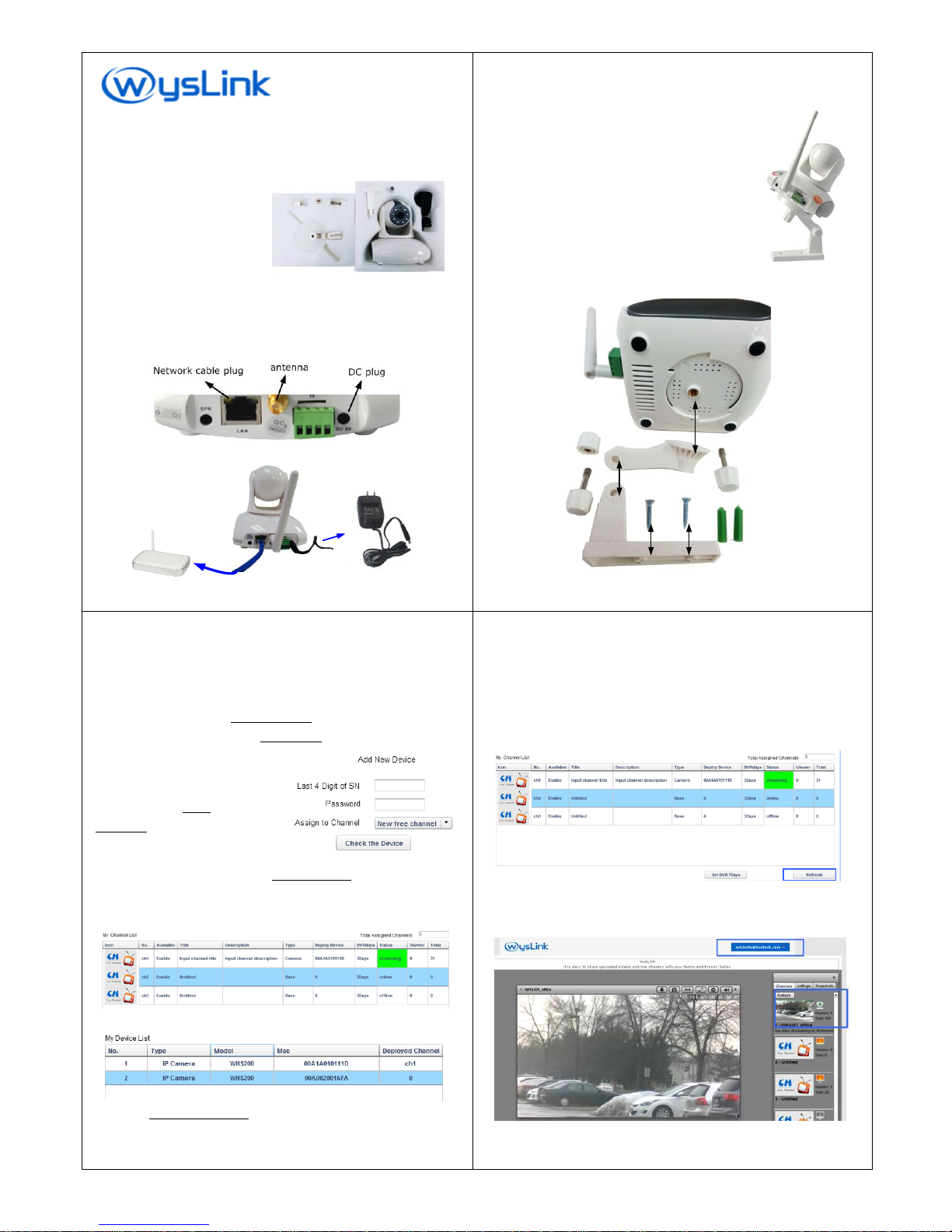
Camera Connection
1. Install the antenna on the camera.
2. Plug one side of a network cable into the LAN port on rear panel
and the other side into your router.
3. Connect the provided 5VDC power adapter to the camera.
Power Adapter
Router
1/8
Camera Mounting
WHS200 is able to be mounted on the wall.
Mounting steps are:
1. Mount bracket 1 on the wall using two wall
anchors with screws;
2. Set WHS200 on bracket 2 using blot 2;
3. Fix bracket 2 on bracket 1 using blot 1 and
nut;
4. Adjust the angle of bracket 1 and bracket
2 to find a proper direction.
blot 1 & nut
bracket 1
blot 2
bracket 2
wall anchors with
screws
2/8
Camera Registration on wysLink.com
Please register your IP camera on wyslink.com following the next
steps.
1. Create an account on www.wysLink.com and activate it. If
you already have a wysLink account, please ignore this step.
Then log in and enter Channel Editor.
2. In Channel Editor, click the Edit Device button.
Add Your Device:
Input the last 4 digit of S/N and
Password to find your camera.
S/N: HS201311E023
Password is printed on the label.
3. Now, your camera is listed in My Device List.
Assign Your Device to a Channel: (omit this step if it is directly assigned to a
channel already at step 2 )
Click an available channel that is not assigned to other devices.
Click your camera row to select it.
Then click Assign to Channel button to put this camera into your
selected channel.
3/8
Watch Live Video
After registration, please connect your camera with network, then
power on.
1. After power on your camera, please wait about 30 seconds.
2. Click Refresh button below My Channel List.
3. When the channel status displays “streaming”, your camera
streams live video to your channel,.
4. Click your account dropdown list at the top-right corner of the
webpage and then click My Stage. Now you enter your stage.
5. Click your channel icon. You can watch your video on stage.
4/8
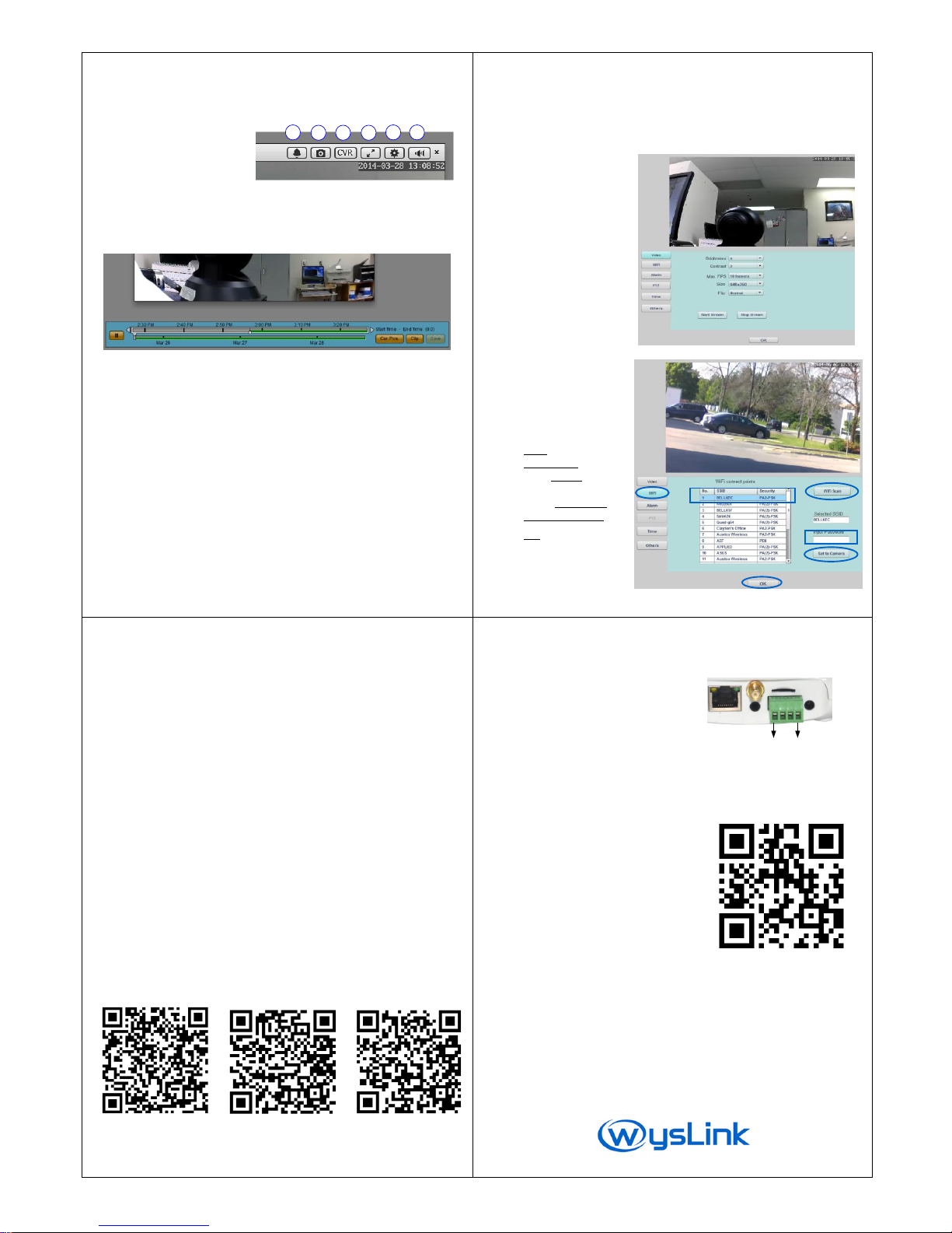
Control on My Stage
All control buttons are located on the top of the displayer on My
Stage.
Alarm Indicator
Snapshot
Watch Recorded Video
Full Screen Display
Camera Settings
Volume Control
1
2 3 4
5 6
Watch Recorded Video on Cloud
This function is for premium member only.
1. Drag the white marker on the date bar (the lower bar) to
select the video date.
2. Click the time bar (the upper bar) to select the exact time.
Save Recorded Video at Local
1. Ctrl + click the time bar to select the start time.
2. Alt + click the time bar to select the end time.
3. Click Clip button and wait for finishing download.
4. Click Save button and select the save path.
5. Click Live button on the top of the player to return live
video.
5/8
Camera Settings on Channel Editor
1. Enter Channel Editor Webpage.
2. Click the channel assigned to your camera.
3. Click Device Config button below My Channel List. You can set
video, Wi-Fi, alarm, PTZ, Time.
Video Settings:
Brightness
Contrast
Frame rate (FPS)
Image size
Image direction
If you would like to
save your network
traffic, please set
small size and low FPS.
Wi-Fi Setting:
Before setting up WiFi,
Please make sure power
Cable and LAN cable are
Connected to camera.
Click WiFi button.
Click WiFi Scan button.
Click WiFi name to
select your WiFi.
Input WiFi password.
Click Set to Camera.
Click OK button.
Please turn off the power
and remove LAN cable.
Wait for about 4 minutes
then turn on the power to restart your camera . 6/8
Camera Specification
Vide o
compression format
H. 26 4
Resolution
HD(1 28 0×720 ), VG A( 64 0×360)
QVGA ( 32 0×18 0)
Image sensor
CM OS 1 M Pi xe l s
Lens
3. 6 mm ( ad justabl e)
Frame rate
up to 25 f ps
Image adjustment
bright ne ss , con tr as t
WB, BLC
auto
Audi o
G.711 / G.726
only f or l iv e v id eo
Networ k
Interface
RJ-45 /1 00 Mb
Wireless
Wi-F i 8 02. 1 1 b/ g/ n
Protocols TC P/ IP , H TT P, D HCP , SM TP , R TM P, w ys Li nk Pl ug &P lay
Alar m
Motion detection
sup p or t
Input/Output
1chane l /1 c h an ne l
Alarm notification
by m ai l or s hot m es sage vi a wy sLink .c om
(P remi um m em b er o nl y)
Pan/Ti lt
Horizontal/ Vertical
355° / 120°
Preset position
7 p o si ti on s
Nig ht Vi si on
LED
8×Φ5 L ED l ig h ts
IR distance
10 m et er
Smart Phone Apps
Android iPhone iPad
Please scan above QR codes to download the application. Or please
search wysLink on Google show for Android, itunes iphone or iPad.
7/8
Camera I/O Panel
Alarm connector Pin assignment
Input
Pin 3 TTL Input,
low active or short with pin4
Pin 4 COM of input
Output
Pin 1 COM of output
1 2 3 4
Pin 2 TTL high level when alarm event occurs;
it keeps for 30 seconds then returns low level.
More Information
For more information about your
camera or related software
applications, please visit our
website www.wyslink.com.
Notes:
It is a cloud IP camera to be accessed via our cloud service platform,
wysLink.com. The camera can also be locally or globally accessed by inputting its
local IP address on a browser, which is available to users who have some
knowledge about IT and network. If changed camera parameters during local
access cause camera abnormal on wysLink.com, users assume responsibility.
Designs and specifications are subject to change without notice,
please visit www.wyslink.com for updated information.
2014/12/05 version 1.2
8/8
 Loading...