

Wyrestorm SW-0501-HDBT Installation Manual
Copyright © 2015 WyreStorm Technologies | wyrestorm.com
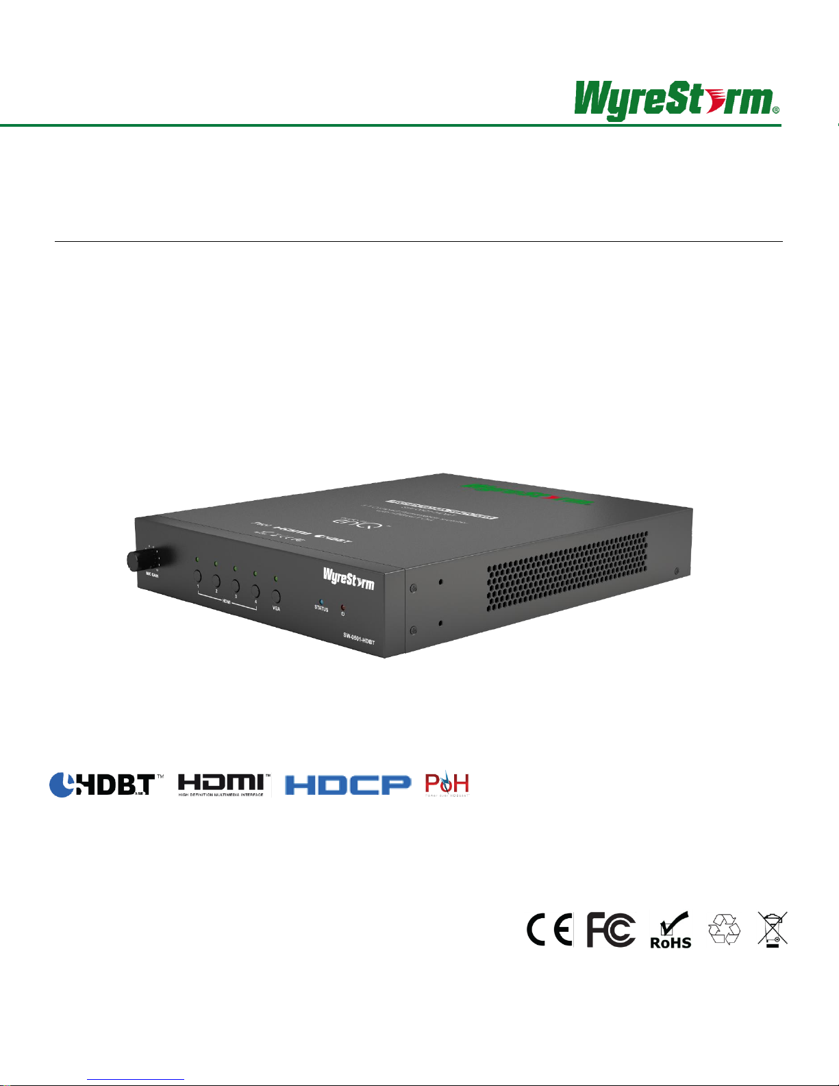
SW-0501-HDBT
5x1 Presentation Switcher/Scaler with Mic Input | CEC Control (1080p to 100m/328ft)
Installation Guide
Thank you for choosing this WyreStorm product.
Please read these instructions carefully before installing to avoid complications later.
2 of 22
SW-0501-HDBT HDBaseT Presentation Switcher/Scaler Installation Guide | 160211-1512
Note:
Provides special information for installing, configuring, and operating the equipment.
IMPORTANT!
Provides special information that is critical to installing, configuring, and operating the
equipment.
CAUTION!
Provides special information on avoiding situations that may cause damage to
equipment.
WARNING!
Provides special information on avoiding situations that may cause physical danger to
the installer, end user, etc.
ELECTRIC SHOCK!
The source power poses an electric shock hazard that has the potential to cause
serious injury to installers and end users.
ELECTRICAL DISCONNECT:
The source power outlet and power supply input power sockets should be easily
accessible to disconnect power in the event of an electrical hazard or malfunction.
WEIGHT INJURY!
Installing some of the equipment requires two installers to ensure safe handling during
installation. Failure to use two installers may result in injury.
IMPORTANT! Safety Information
Safety Classifications
Safety Statements
1. Read these instructions in their entirety and retain a copy for later reference.
2. Follow all instructions and heed all warnings.
3. Do not expose this apparatus to rain, moisture, sprays, drips or splashes and ensure that no objects containing liquids are placed on the
apparatus, including cups, glasses and vases.
4. Do not place this unit in a confined space such as enclosed shelving, cabinets or bookshelves. Ensure the unit is adequately ventilated.
5. To prevent the risk of electric shock or fire hazard due to overheating, do not cover the unit or obstruct ventilation openings with material,
newspaper, cardboard or anything that may restrict airflow into the unit.
6. Do not install near external heat sources such as radiators, heat registers, boilers or any device that produces heat such as amplifiers or
computers and do not place near sources of naked flame.
7. Unplug apparatus from power supply during lightning storms or when unused for long periods of time.
8. Protect the power cable from being walked on, pinched or restricted in any way, especially at plug connections.
9. Only use attachments/accessories specified by the manufacturer.
10. Units contain non-serviceable parts - Refer all servicing to qualified service personnel.
IMPORTANT!
Do Not Hot swap HDMI or HDBaseT connections - Please insert and extract cables carefully with the power SWITCHED OFF. Power is
passed along transmissions so connecting and disconnecting cables while powered can result in damage to circuitry or possible injury.

Copyright © 2015 WyreStorm Technologies | wyrestorm.com
3 of 22
Contents
IMPORTANT! Safety Information ...................................................................................................................................... 2
1. Product Overview .......................................................................................................................................................... 4
Key Features ...................................................................................................................................................................................................... 4
In the Box ........................................................................................................................................................................................................... 4
Front Panel ......................................................................................................................................................................................................... 5
Rear Panel .......................................................................................................................................................................................................... 6
Specifications ..................................................................................................................................................................................................... 7
2. Wiring and Connections ............................................................................................................................................... 8
HDMI and VGA Wiring ........................................................................................................................................................................................ 8
Microphone Wiring .............................................................................................................................................................................................. 8
Audio In Wiring ................................................................................................................................................................................................... 8
Audio Out Wiring ................................................................................................................................................................................................ 8
Local Area Network (LAN) Wiring ....................................................................................................................................................................... 8
HDBaseT Wiring ................................................................................................................................................................................................. 8
IR Wiring ............................................................................................................................................................................................................. 9
Remote I/O Control Device Wiring ..................................................................................................................................................................... 9
RS-232 Wiring .................................................................................................................................................................................................. 10
3. Installation .................................................................................................................................................................... 12
Basic Wiring Diagram ....................................................................................................................................................................................... 12
Audio/Video Connections ................................................................................................................................................................................. 13
Control and LAN Connections .......................................................................................................................................................................... 14
4. Switcher Configuration ............................................................................................................................................... 15
First Time Use Configuration ............................................................................................................................................................................ 15
Accessing the Web User Interface (Web-UI) .................................................................................................................................................... 15
Configuring Source Auto Switching .................................................................................................................................................................. 15
Configuring EDID Operation ............................................................................................................................................................................. 16
Configuring the Audio Output ........................................................................................................................................................................... 16
Display Power Management Configuration ...................................................................................................................................................... 17
Changing Web-UI Login Password .................................................................................................................................................................. 17
Rebooting and Restoring Factory Defaults ....................................................................................................................................................... 18
Viewing Switcher Information ........................................................................................................................................................................... 18
5. Troubleshooting .......................................................................................................................................................... 19
6. Warranty and Service .................................................................................................................................................. 20
Warranty Limits & Exclusions ........................................................................................................................................................................... 20
Obtaining Warranty Service .............................................................................................................................................................................. 20
7. Glossary of Terms ....................................................................................................................................................... 21
Publication Disclaimer .................................................................................................................................................... 22

4 of 22
SW-0501-HDBT HDBaseT Presentation Switcher/Scaler Installation Guide | 160211-1512
1. Product Overview
The SW-0501-HDBT allows for up to 4 HDMI and 1 VGA inputs (+audio). The internal scaler provides instant source switching by
matching the resolution of the sink device up to 1920x1200p. There is also an adjustable microphone input with selectable phantom
power, which can be mixed with source audio and sent via the audio output. Signal transmission is via HDMI or by HDBaseT for
transmission up to 100m. PoH and control signals can be all sent to the RX-70-4K HDBaseT receiver (sold separately).
Key Features
4 HDMI inputs & 1 VGA input
HDBaseT Output with PoH up to 100m
Duplicate HDMI output
Fast seamless switching, with auto-scaler up to 1920x1200
Auto switching between sources, uses last-in/first-out logic
Audio inputs for microphone, and VGA audio embed
Use either dynamic or condenser mics with switchable phantom power
Rotary knob on front panel for Mic gain control
5x I/O ports for signal switching and LED out for desk-mounted connection panel
Automatic CEC trigger on output—Switcher can send power commands to sink devices via CEC or RS-232 Port
Controls power of sink devices, according to the status of input sources via CEC, or RS-232. Supports Bi-directional IR and RS-232
pass-through
Control via RS-232 or LAN
Built-in Web UI for customization of sink device power on/off and advanced settings
In the Box
1x SW-0501-HDBT Presentation Switcher/Scaler
1x AC Power Cord
1x 11-pin Screw Down Phoenix Connector
1x 5-pin Screw Down Phoenix Connector
2x 4-pin Screw Down Phoenix Connector
4x 3-pin Screw Down Phoenix Connector
2x Mounting brackets
1x Quickstart guide
Copyright © 2015 WyreStorm Technologies | wyrestorm.com
5 of 22
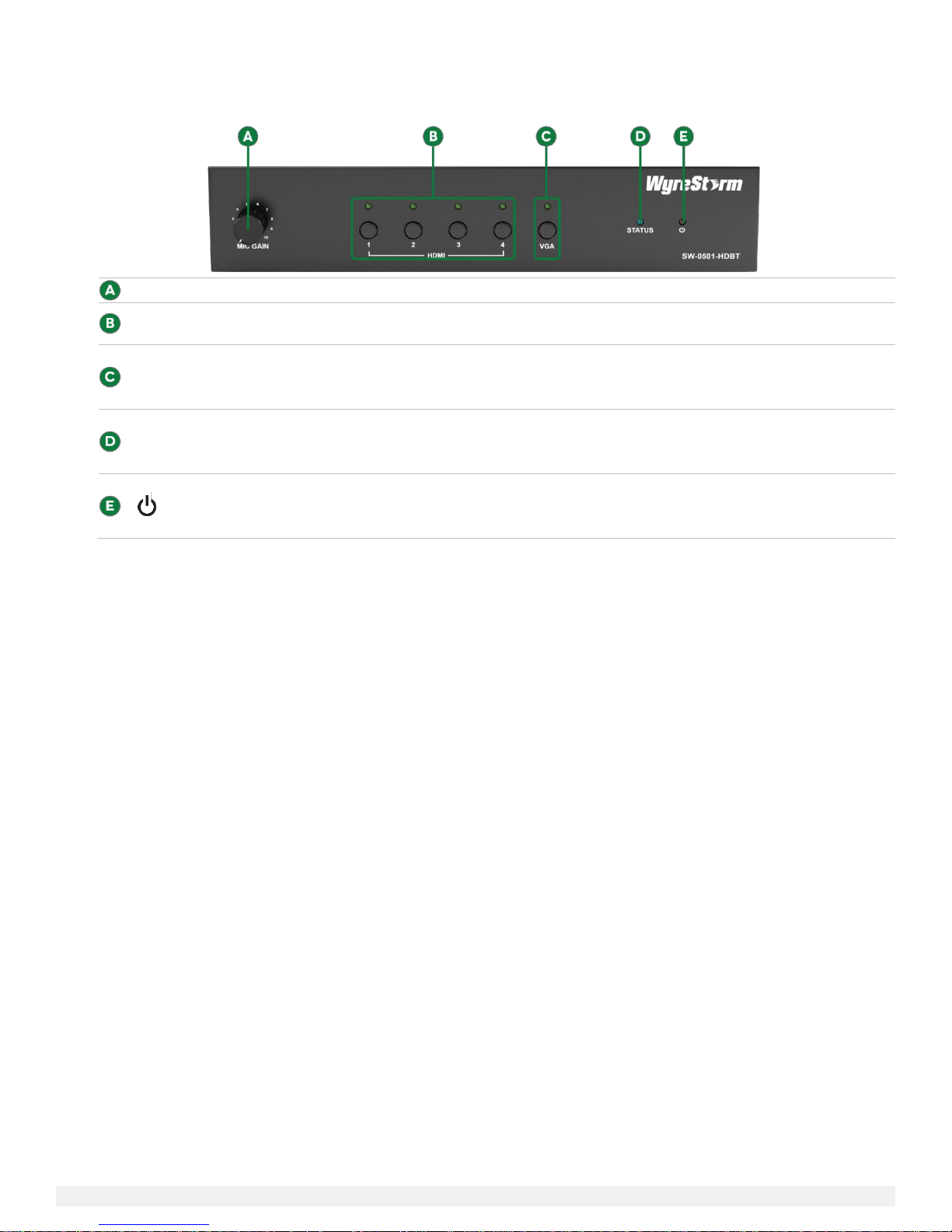
Mic Gain
Adjusts the gain of the Mic Input from 0 to 40db.
HDMI Input 1-4
Selection
Press to select an HDMI input as the current source. An illuminated LED indicates the currently selected
HDMI source.
VGA Input Selection
Press to select VGA input as the current source. An illuminated LED indicates the currently selected source
is VGA.
Status
Flashing (at 2 second intervals): The SW-0501-HDBT is operating normally.
(Power)
Solid: The SW-0501-HDBT is powered On.
Front Panel
6 of 22
SW-0501-HDBT HDBaseT Presentation Switcher/Scaler Installation Guide | 160211-1512
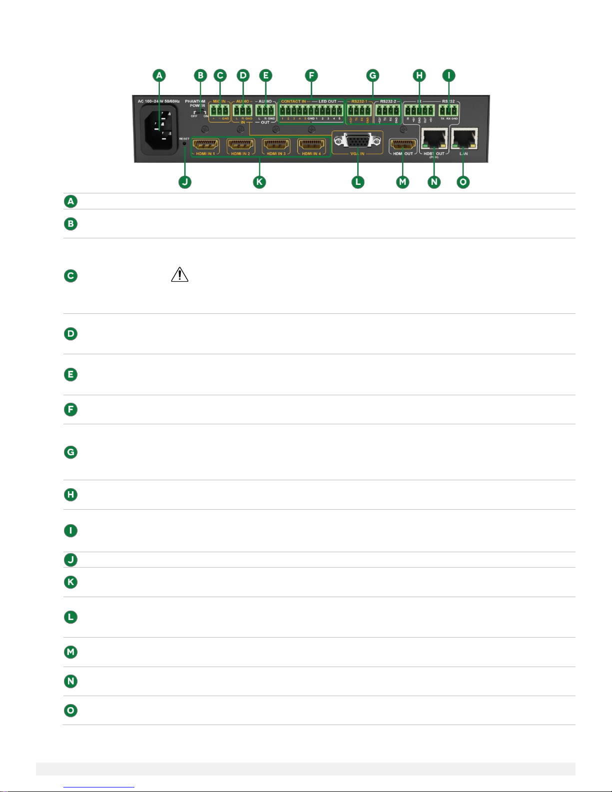
AC Power
Connect to a 100~240V AC 50/60Hz AC mains outlet.
Phantom Power
On: Provides 48V DC 100mA to a microphone connected to Mic In
Off: No power supplied – Use this setting for dynamic (passive) microphones.
Mic In
3-pin Screw Down Phoenix Connector
Connect to a microphone to allow for combining with selected source audio.
IMPORTANT!
Verify that Phantom Power switch on the rear panel is set to Off before connecting dynamic (passive)
microphones.
Audio In
3-pin Screw Down Phoenix Connector
Connect to the analog audio output of the VGA source connected to the VGA In. Audio signal received on
this port is played only when the VGA input is selected.
Audio Out
3-pin Screw Down Phoenix Connector
Connect to the line level input of an audio pre-amplifier or powered speaker for audio output from selected
sources.
Contact In/
LED Out
11-pin Screw Down Phoenix Connector
Connect to a remote I/O control device such as a panel switch for selecting inputs remotely.
RS-232 1-2
4-pin Screw Down Phoenix Connector
RS-232 1 is used for controlling the SW-0501-HDBT via an external control system.
RS-232 2 is used for controlling local devices such as connected sources.
Refer to RS-232 Wiring for more details.
IR
5-pin Screw Down Phoenix Connector
Used to send and receive IR signals to/from the remote display location via HDBaseT.
RS-232
3-pin Screw Down Phoenix Connector
Used to send RS-232 signals to/from devices connected to an HDBaseT receiver via the HDBaseT Out port.
Refer to RS-232 Wiring for more details.
Reset
Press and hold for 5 seconds while the SW-0501-HDBT is powered on to restore factory default settings.
HDMI In 1-4
19-pin type A HDMI female digital video/audio input.
Supports HDMI and DVI/D (requires adapter-not included).
VGA In
15-pin VGA VESA (DSUB 15)
Connect to DSUB 15 VGA output of device such as a computer
15-pin VGA cable is required.
HDMI Out
19-pin type A HDMI female digital video/audio input.
Supports HDMI and DVI/D (requires adapter-not included).
HDBaseT Out
8-pin RJ-45 female
Connect to an HDBaseT receiver.
LAN
8-pin RJ-45 female | 10/100 Mbps auto-negotiating
Connect to a network router or switch for accessing the Web UI or IP Control.
Rear Panel

Copyright © 2015 WyreStorm Technologies | wyrestorm.com
7 of 22
Audio and Video
Audio Formats
2ch analog/2ch PCM
Video Resolution
HDMI: Up to 1920x1200p@60Hz
VGA: Up to 1920x1200@60Hz
Color Depth
36bit
Maximum Pixel Clock
275MHz
Communication and Control
HDBaseT
EDID | CEC | PoH | Bi-directional pass-through IR and RS-232
HDMI
EDID | CEC
DVI/D supported with adapter (not included)
Ethernet
10/100 Mbps auto-negotiating
IR
Bi-directional pass-through over HDBaseT (no switcher control)
RS-232
Switcher Input Selection | Local Device (1x) |
Bi-directional pass-through over HDBaseT (1x)
CEC
Power Management for display connected via HDMI or HDBaseT
Contact Closure
Switcher Input Selection with LED Feedback
Front Panel Buttons
Switcher Input Selection with LED Feedback
Power
Input Power
100~240V AC 50/50Hz
Max Power Consumption
26.5W
PoH
48V 15.4W
Microphone Phantom Power
48V DC 100mA
Environmental
Operating Temperature
32°F ~ 113°F (0°C ~ 45°C)
10% ~ 90%, non-condensing
Storage Temperature
-4°F to ~ 158°F (-20°C ~ +70°C)
10% ~ 90%, non-condensing
Dimensions and Weight
Height
50mm / 1.9in
Width
220mm / 8.6in
Depth
270mm / 10.6in
Weight
2.0kg / 4.40lbs
Regulatory
Safety and Emission
CE | FCC
Specifications
 Loading...