

Wyrestorm NHD-400-RX v1, NHD-400-TX Quick Start Manual
IMPORTANT! Installation Requirements!
• Visit the NetworkHD product pages download section at wyrestorm.
com to check for the latest rmware, document versions, and WyreStorm
Management Suite conguration tools.
• Install the latest rmware onto all encoders and decoders using the
Maintenance Tool found in the Management Suite and via the NHD-000CTL web interface. Full rmware update instructions are included with the
rmware download.
• NetworkHD requires a Layer 2 managed switch network with support for
Multicast & IGMP snooping enabled.
• WyreStorm highly recommends using network switches listed in the
NetworkHD Switch Recommendation Guide. These switches have been
veried by WyreStorm to meet the requirements of a NetworkHD system.
• Congure all network switches to the exact specication of the guides at
wyrestorm.com prior to connecting any NetworkHD devices.
• NetworkHD uses AutoIP to assign IP addresses in the range of 169.254.x.x
to encoders and decoders out of the box. Your PC must be set to an
address in this range in order to discover the encoders, decoders and
NHD-000-CTL.
• WyreStorm recommends the use of the NHD-000-RACK2 for installations
containing multiple NetworkHD devices. Use of this product provides an
enclosure to mount and secure all NetworkHD devices in a rack.
• If using a mix of HD & UHD resolution displays with differing HDCP versions
and for HDMI 1.4/HDCP 1.4 displays – Ensure the decoder is set to HDCP
1.x by right clicking the unit in the NetworkHD Console and opening the
video settings option.
In the Box
1x NHD-400-TX or NHD-400-RX
1x 12V DC 1A Power Supply
1x Wide-band IR Emitter
1x Wide-band IR Receiver (30-50KHz)
2x Mounting Brackets
1x Quick Start Guide (This Document)
Additional Information
More information and required software can be found within the Download
section of the product page on wyrestorm.com.
• Management Suite v1.1.0 or Higher
• NetworkHD Switch Recommendations
• NetworkHD Switch Mapping Worksheet
• NetworkHD Switch Conguration Guides
• NetworkHD Touch Installation Guide
• NetworkHD Touch User Guide
• Drivers for Popular Control Systems
Copyright © 2017 WyreStorm Technologies | wyrestorm.com
NHD-400-TX | NHD-400-RX v1 Quickstart Guide | 170406
North America: 518-289-1294 | EMEA/ROW: 44 (0) 1793 230 343
support@wyrestorm.com
1 of 4
WyreStorm recommends reading through this document in its entirety to become familiar with the product’s features prior to starting the
installation process.
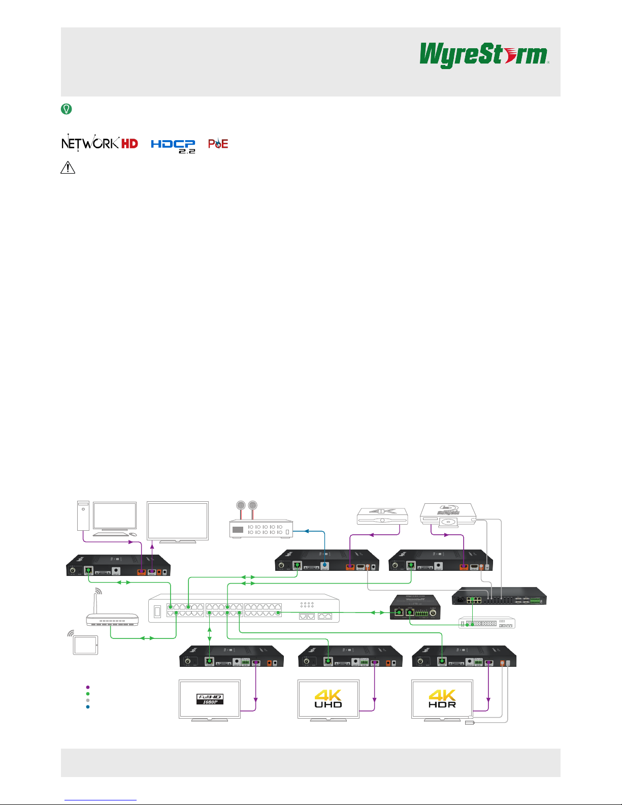
Basic Wiring Diagram
Quickstart Guide
NHD-400-TX | NHD-400-RX v1
4K UHD IP JPEG2000 Streaming Encoder and Decoder
Wifi Router
Local DisplayPersonal Computer
NHD-400-TX
NHD-400-TX
NHD-400-RX NHD-400-RX NHD-400-RX
iPad with
NetworkHD Touch
NHD-400-TX
UHD Sattellite Box
Audio Distribution
Amplifier
UHD BluRay Player
NHD-000-CTL
Control System
Key
Digital Video/DVI/HDMI
Ethernet
IR
Analog Audio
Copyright © 2017 WyreStorm Technologies | wyrestorm.com
NHD-400-TX | NHD-400-RX v1 Quickstart Guide | 170406
North America: 518-289-1294 | EMEA/ROW: 44 (0) 1793 230 343
support@wyrestorm.com
2 of 4
Wiring and Connections
WyreStorm recommends that all wiring for the installation is run and terminated prior to making connections to the switcher. Read through this section in this
entirety before running or terminating the wires to ensure proper operation and to avoid damaging equipment.
HDMI / Cat5e/6 Wiring
IMPORTANT! Wiring Guidelines
• The use of patch panels, wall plates, cable extenders, kinks in cables, and
electrical or environmental interference will have an adverse effect on HDMI
and Ethernet transmission limiting performance. Steps should be taken to
minimize or remove these factors completely during installation for best
results.
HDMI Wiring
WyreStorm recommends using pre-terminated HDMI cables due to the
complexity of these connector types. Using pre-terminated cables will
ensure that these connections are accurate and will not interfere with the
performance of the product.
Control Wiring
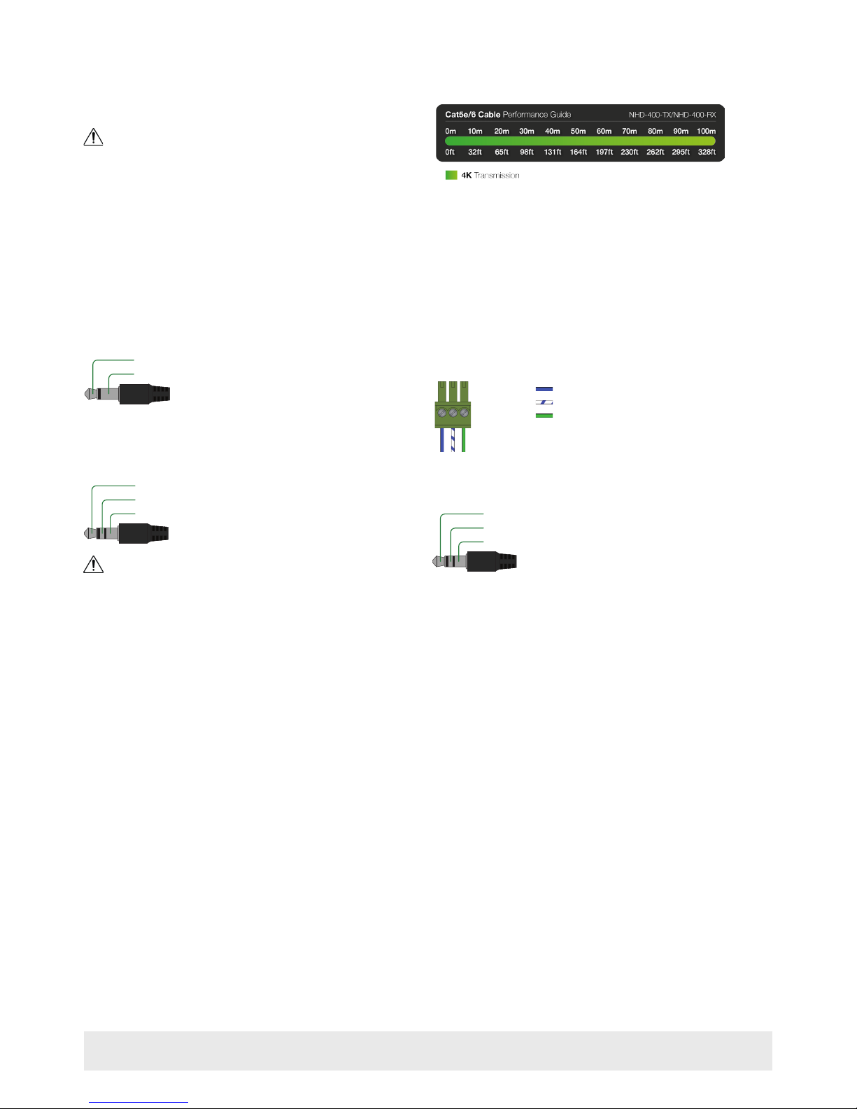
IR TX (Emitter) Wiring
Connection for IR TX (transmit) uses a 3.5mm (1/8in) mono plug.
Tip: IR Signal
Sleeve: Ground (GND)
IR RX (Receiver) Wiring
Connection for IR RX (receive) uses a 3.5mm (1/8in) stereo jack that outputs
+5V DC to power the included IR receiver.
Tip:
Ring: IR Signal
+5V DC
Sleeve: Ground (GND)
IMPORTANT! IR TX Connection Guidelines
• 3rd party IR receivers may require a different voltage, refer to the
documentation provided with the IR receiver before making any connections
to avoid damaging the device.
• When connecting to an IR control system use the WyreStorm CAB-IR-LINK
cable. This cable compensates for differences between the WyreStorm RX
and the control systems TX connection. Visit the CAB-IR-LINK product
page for details.
RS-232 and Debug Wiring
Most control systems and computers are DTE where pin 2 is RX, this can vary
from device to device. Refer to the documentation for the connected device
for pin functionally to ensure that the correct connections can be made.
Wire colors shown follow EIA-561 standard.
Pin 1:
Pin 2:
TX (Transmit)
RX (Receive)
Pin 3:
Ground (GND)
1 2 3
Audio Out Wiring
The audio connections use a 3.5mm (1/8in) TRS Stereo Jack.
Tip:
Ring:
Left Channel
Right Channel
Sleeve: Ground (GND)
 Loading...