

Wyrestorm NHD-220-RX Quick Start Manual
NetworkHD™ 200 Series AV Over IP H.264
Multiview Decoder
NHD-220-RX Quickstart Guide
IMPORTANT! Installation Requirements!
• Visit the product page to download the latest rmware, document
versions, and the WyreStorm Maintenance Suite conguration tools.
• Install the latest rmware onto all NetworkHD devices in the system.
• NetworkHD requires a Layer 2 managed switch network with support
for Multicast & IGMP snooping enabled.
• NetworkHD uses AutoIP to assign IP addresses in the range of
169.254.x.x to encoders and decoders out of the box. The use of DHCP
addresses is not recommended. Errors in static IP settings can result
in a complicated reset procedure.
• WyreStorm highly recommends using our recommended switch
manufacturers. Congure all network switches to the exact
specication of the guides at wyrestorm.com prior to connecting any
NetworkHD devices.
• Due to the way H.264 compression encodes the video, interlaced video
sources are not recommended. Please use progressive scan sources
for best video quality - even at lower resolutions.
• WyreStorm recommends the use of the NHD-000-RACK for
installations containing multiple NetworkHD devices. Use of this
product provides an enclosure to mount and secure all NetworkHD
devices in a rack.
In the Box
1 x NHD-200-RX Main Unit
1 x Power Adapter (12V 1A DC)
3 x 3-pin Phoenix Connectors
2 x Mounting Brackets
1 x Quickstart guide (This Document)
Additional Information
The following information can be found on the WyreStorm website under
the NHD-220-RX Product Page.
• NetworkHD 100-200 Series Firmware
• NetworkHD 200 Series Installation Guide
• NetworkHD Switch Recommendations
• NetworkHD IP Switch Mapping Worksheet
• NetworkHD Switch Conguration Guides
• Drivers for Popular Control Systems
Copyright © 2016 WyreStorm Technologies | wyrestorm.com
NHD-220-RX Quickstart Guide | 160330
North America: 518-289-1294 | EMEA/ROW: 44 (0) 1793 230 343
support@wyrestorm.com
1 of 4
WyreStorm recommends reading through this document in its entirety to become familiar with the product’s features prior to starting the
installation process.
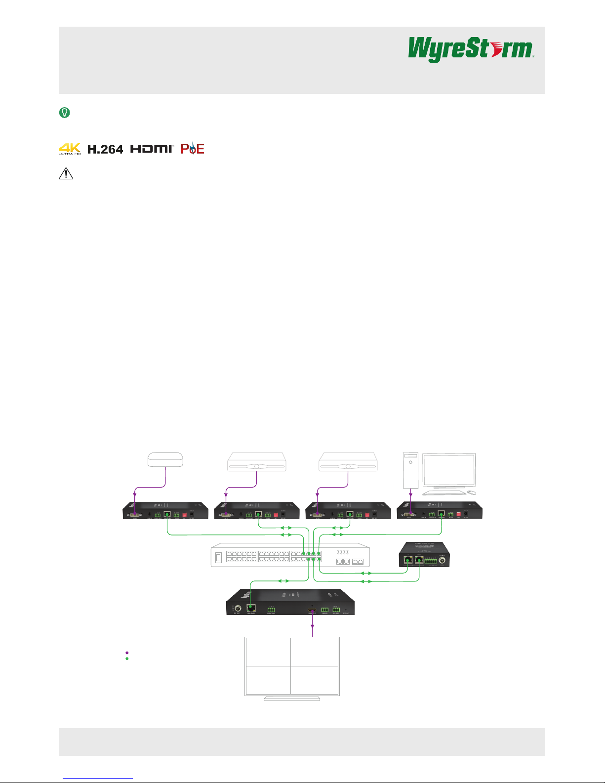
Basic Wiring Diagram
The following diagram is provided to illustrate a typical basic system containing the NHD-220-RX.
Network Switch
NHD-220-RX
NHD-200-TX NHD-200-TX
NHD-200-TX
NHD-200-TX
NHD-000-CTL
Ethernet
Ethernet
Ethernet
Digital Video Digital Video Digital Video
Digital Video
Digital Video
Media Player
Ethernet
Sattellite Box 1 Sattellite Box 2 PC
Satellite Box 1 Satellite Box 2
PCMedia Player
Digital Video/DVI/HDMI
Key
Ethernet
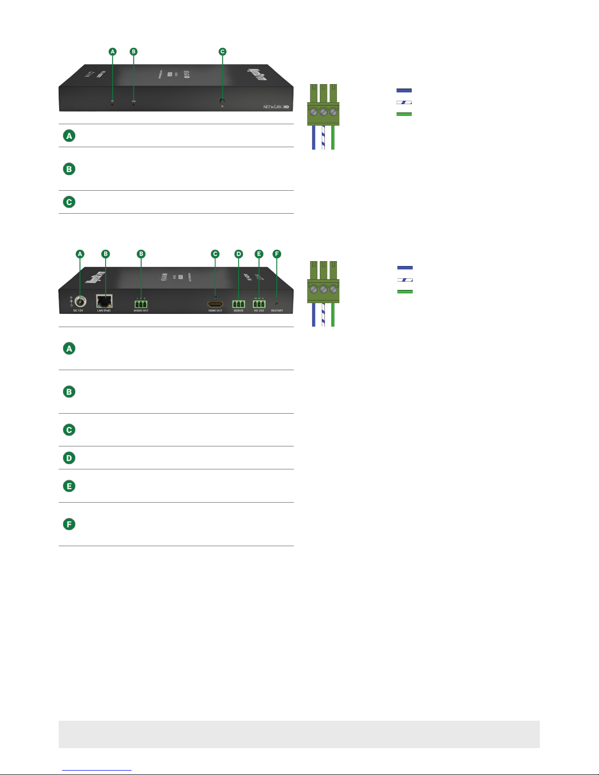
Front Panel
Power Button
On – Device is On
Off – Device is Off
Link LED
On – Device is operating and in a normal
working state.
Off – Device is not in a normal state and
may experience incorrect operation.
ID
Displays the decoder and encoder MAC
addresses onscreen.
Rear Panel
Power Input
5.5mm Screw Down Barrel Jack
Connect to the included18V DC 1A power
supply when not powering via PoE from the
switch
LAN (PoE)
8-pin RJ-45 female | 10/100 Mbps auto-
negotiating
Connect to the same network switch that
the NetworkHD encoders are connected to.
Audio Out
3-pin Phoenix Connector
Provides 2ch stereo audio from the currently
playing stream
HDMI Out
19-pin type A HDMI female
Supports HDMI and DVI/D with adapter
Debug
3-pin Phoenix Connector
Connect to a PCs serial port for debugging
the device.
RS-232
3-pin Phoenix Connector
Provides RS-232 pass-through of
commands from the NHD-000-CTL to
control the display device.
Audio Out Wiring
The decoder contains an Audio Out that can be used to distribute the
audio throughout the room by connecting to an audio pre-amplier
or powered speaker. This connection uses a 3-pin phoenix connector
(supplied).
Pin 1:
Pin 2:
Left Positive (+)
Right Positive (+)
Pin 3: Ground (GND)
Wire colors shown are for pin identificaiton only and do not
represent any wiring standard.
1 2 3
RS-232 and Debug Wiring
Connection Guidelines
The following wiring diagram shows the pinouts for the decoder.
While not shown, connect the TX (transmit) to RX (receive) pins at the
controlled device or PC side of the cable.
Most controllable devices are DCE where pin 2 is TX, this can vary from
device to device. Refer to the documentation for the connected device for
pin functionally to ensure that the correct connections can be made.
Wire colors shown follow EIA-561 standard.
Pin 1:
Pin 2:
TX (Transmit)
RX (Receive)
Pin 3:
Ground (GND)
1 2 3
Copyright © 2016 WyreStorm Technologies | wyrestorm.com
NHD-220-RX Quickstart Guide | 160726
North America: 518-289-1294 | EMEA/ROW: 44 (0) 1793 230 343
support@wyrestorm.com
2 of 4
 Loading...