

Wyrestorm MX-0816-HDBT Instruction Manual
Thank you for choosing this WyreStorm product.
Please read these instructions carefully before installing to avoid complications later.
Instruction Manual
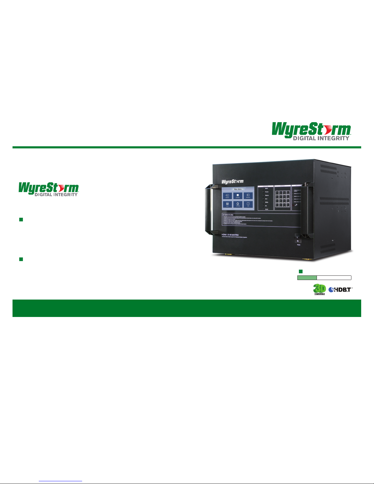
8 x 16 Output Full HD Matrix Switch
Part Number
MX-0816-HDBT
www.wyrestorm.com
WyreStorm Offices
US Office: 6991 Appling Farms Parkway, Suite 104, Memphis, TN 38133
Tel: + 901 384 3575 Fax: + 901 384 3574
Unit 22, Ergo Business Park, Swindon, Wiltshire, SN3 3JW UK
Tel: +44 (0) 1793 230 343 Fax: +44 (0) 1793 230 583
WyreStorm Technical Support
US: +86 6677 0053
UK:- +44 (0) 1793 238 338
Email: support@wyrestorm.com
We reserve the right to change specification or product dimensions at any time.
3
Technical Support: support@wyrestorm.com US: +866 677 0053 EU: +44 (0) 1793 230 343
4
Technical Support: support@wyrestorm.com US: +866 677 0053 EU: +44 (0) 1793 230 343
FEATURES AND SAFETY PRE CAUTIONS
CONTENTS AND INTR ODUCTION
1 Introduction
2 Features
3 Safety Precautions
4 Package Contents
5 Specifications
6 Front Panel Description
7 Rear Panel Description
8 Typical Application
9 Connections
10 Basic Operation
11 Advanced Operation
12 Troubleshooting
13 FAQs
14 Maintenance
15 Provided Service
16 Mail-in- Service
17 Warranty
18 Warranty limits and Exclusions
19 Reference Logs
• Allows up to 8 HDM I audio/video devices to be independently
switched through up to 16 HDMI displays or projectors
• Each output requires a UTP receiver behind each display used:
Contents 2. Features
3. Safety Precautions
1. Do not expose this apparatus to rain, moisture, sprays,
drips or splashes and ensure that no objects containing
liquids are placed on the apparatus, including cups,
glasses and vases.
2. Do not place this unit in a confined space such as
enclosed shelving, cabinets or bookshelves. Ensure the
unit is adequately ventilated.
3. To prevent the risk of electric shock or fire hazard due to
overheating, do not cover the unit or obstruct ventilation
openings with material, newspaper, cardboard or
anything that may restrict airflow into the unit.
4. Do not install near external heat sources such as
radiators, heat registers, boilers or any device that
produces heat such as amplifiers or computers and do
not place near sources of naked flame.
5. Unplug apparatus from power supply during lightening
storms or when unused for long periods of time.
6. Protect the power cable from being walked on, pinched
or restricted in any way, especially at plug connections.
7. Only use attachments/accessories specified by the
manufacturer.
8. Units contain non-servicable parts - Refer all servicing to
qualified service personnel.
WARNING
To reduce the risk of fire, electric shock
or product damage:
• Each output features integrated single RJ45 outputs
• Reads and copies EDI D from connected devices
• 3D compatible and fully supports all high denition resolutions:
1080p. 1080i, 720p
• Each output card offers RS232 pass-through
• Each port supports both HDM I and DVI signals
• Choose from eight switching modes – remote control, touch
screen, panel buttons, Local IR, IR call back from remote
locations, RS232, RS485, and Ethernet
• Memory function to save your matrix settings
• Touch screen/display screen previews and observes the source
• IR code edit function
• Rened for Custom Install and Home Theatre installations
• Constant HDC P preventing screen drop-outs
• Control signals can be sent from matrix to screen via 2-way IR
• Single cable solution including transmission of full
HD audio/video, RS232, 2-Way IR and Ethernet
• 1080p up to 100m (328ft) range using Cat5e/6/7 UTP
(including 3D applications)
• Fully supports 48bit Deep Colour
• HDC P compliant, EDID Management
• Totally discrete IR source control allowing easy install of
duplicate HD sources
• Accessories include: 19” rack brackets, IR receiver,
IR emitters and matrix remote control
• Open source RS232 drivers available for third
party products
• 10.2 Gbps bandwidth output capacity.
NOTE: WyreStorm reserves the right to make changes to
hardware, packaging and any accompanying documentation
without prior written notice.
The MX-0816-HDBT is a 8x16 matrix switcher that allows
any of its 8 HDMI inputs to be routed over distance to
any combination of the 16 display outputs via UTP cable,
regardless of HDCP source encryption.
The use of HDBaseT ‘one cable’ technology enables the
MX-0816 to deliver HD audio and video, multiple control options
and high speed internet access through a single Cat 5e/6/7
cable, with a transmission distance of up to 100m (328ft) for
1080p.
The system has versatile control, with users able to choose from
several methods of controlling the matrix – Infrared (IR) emitters
and receivers, RS232, RS485, LAN, touch screen, panel button, or
by using the remote control included in the package.
The MX-0816-HDBT offers incredible flexibility and reliability
of signal distribution combined with innovative features and an
ease of use that provides solutions where HD transmission over
distance to multiple displays is required, whilst also eliminating
the need for additional control and video cables on installation,
whether in a residential or commercial setting.
Part Number
MX-0816-HDBT
1. Introduction
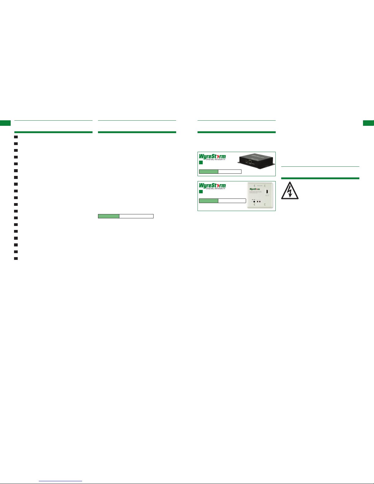
HDBaseT Single
Cat5e/6/7 Display Receiver
Part Number
RX-100IR-HDBT
In-wall HDBaseT Single
Cat5e/6/7 Display Receiver
Part Number
RX-100IR-HDBT-IW
5
Technical Support: support@wyrestorm.com US: +866 677 0053 EU: +44 (0) 1793 230 343
6
Technical Support: support@wyrestorm.com US: +866 677 0053 EU: +44 (0) 1793 230 343
FUNCTION KEYPAD INDICATOR
FRONT PANEL, REAR PANEL
PACKAGE CONTENTS, SPECIFICATIONS, FRONT PANEL, R EAR PANEL
• MX-0816-HDBT main unit
• Instruction manual
• CD including PC software and copy of instruction manual
• Mounting brackets
• Stylus (for touch screen)
• 1 x 100-240v AC power cable/adapter
• 1 x USB to RS232 cable
• 1 x RS232 to RS485 converter
• 1 x IR RX Receiver (larger sensor for H D display)
• 8 x IR TX Emitters (small sensor for Input source)
• 1 x MX-0816-HDBT remote control (incl. battery)
4. Package Contents
Operating Temperature
Range
-5 to +35°C (-41 to +95°C)
Operating Humidity Range 5 to 90 % RH
(no condensation)
Video Amplier Bandwidth 2.25Gbps
Input Video Signal 0.5-1.0 volts p-p
Input DDC Signal 5 volts p-p (TTL)
Maximum Single Link Range 1080p Deep Colour
Transmission distance 1080p signal up to
100m / 328ft (under perfect
transmission conditions. See
FAQ on p.19)
Video Format Supported VESA: 640x480, 800x600,
1024x768, 1280x1024,
1600x1200, 1920x1200
DTV/HDTV:
480i/576i/480p/576p/720p/
1080i/1080p
Output Video High Speed HDMI
(or ‘category 2’) See FAQ on
p.19 for details.
Power Consumption 60 Watts (max.)
Power Supply 100-240V AC
Dimensions 440mm / 17.3” (W)
350mm / 13.7” (H)
390mm / 15.5” (D)
Weight 20 Kg / 44lbs
5. Specifications
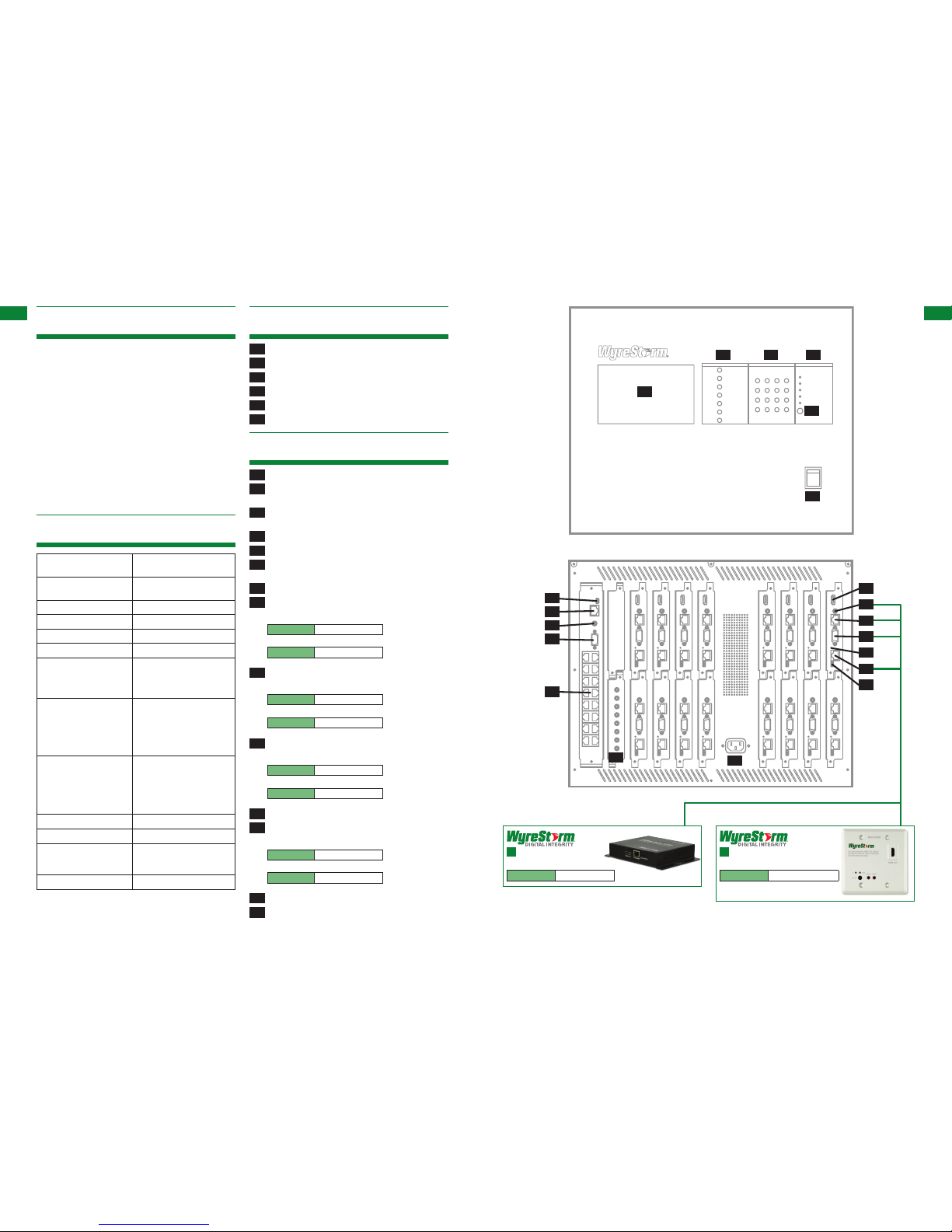
6. Front Panel
01 Touch panel / preview display
02 Function options (for alternative selection)
03 Numeric keypad (for source / display selection)
04 Operational LED (lit when active)
05 Remote control IR sensor
06 Power on/off switch
7. Rear Panel
07 ISP port - for firmware updates
08 LAN port - for controlling the matrix remotely over an I P
network
09 I R extension port - for control when the matrix is out of view
out of view, such as in a rack or enclosed shelving system.
10
RS232 port - alternative control of the matrix via RS232 cable
11
RS485 port - alternative control of the matrix via RS485 cable
12 IR TX Emitter ports - numbered 1-8 to correspond to inputs
1-8
13 HDMI inputs - numbered 1-8
14 IR RX Receiver ports - numbered 1-16 to connect to:
HDBaseT Single Cat5e/6/7 Display Receiver
Part Number
RX-100IR-HDBT
In-wall HDBaseT Single Cat5e/6/7 Display Receiver
Part Number
RX-100IR-HDBT-IW
15 Ethernet port - to connect to display receiver:
HDBaseT Single Cat5e/6/7 Display Receiver
Part Number
RX-100IR-HDBT
In-wall HDBaseT Single Cat5e/6/7 Display Receiver
Part Number
RX-100IR-HDBT-IW
16 RS232 port to connect to display receiver:
HDBaseT Single Cat5e/6/7 Display Receiver
Part Number
RX-100IR-HDBT
In-wall HDBaseT Single Cat5e/6/7 Display Receiver
Part Number
RX-100IR-HDBT-IW
17 Link status LED - lit when UTP connection established
18 UTP output - to connect to display receiver
HDBaseT Single Cat5e/6/7 Display Receiver
Part Number
RX-100IR-HDBT
In-wall HDBaseT Single Cat5e/6/7 Display Receiver
Part Number
RX-100IR-HDBT-IW
19 ISP port for firmware updates
20 Power cable input
01
02 03 04
05
06
07
08
09
10
11
14
15
16
17
18
19
20
12
13
HDBaseT Single
Cat5e/6/7 Display Receiver
Part Number
RX-100IR-HDBT
In-wall HDBaseT Single
Cat5e/6/7 Display Receiver
Part Number
RX-100IR-HDBT-IW
Front Panel
Rear Panel
7
Technical Support: support@wyrestorm.com US: +866 677 0053 EU: +44 (0) 1793 230 343
8
Technical Support: support@wyrestorm.com US: +866 677 0053 EU: +44 (0) 1793 230 343
BASIC OPERATION
TYPICAL APPLICATION, CONNECTION
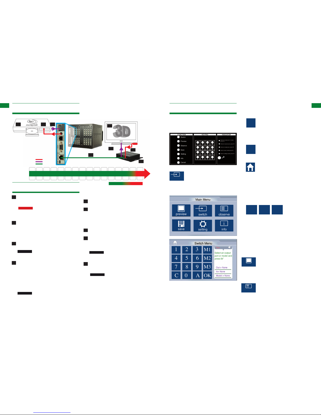
49ft32ft16ft 65ft 82ft 98ft 114ft 131ft147ft 164ft 196ft 229ft 262ft 295ft 328ft
15m10m5m 20m 25m 30m 35m 40m 45m 50m 60m 70m 80m 90m 100m
KEY
IR
HDMI
Cat 5e
HDMI Source
IR TX emitter
placed over or
near device
infrared sensor
IR TX jack
plugged in to
IR RX port of
Matrix
Cat5e (up to 100m 328ft)
Screen
HDMI
Cable
IR RX receiver
placed discretely
on the display
with a clear line
of sight to the
infrared remote
control being
used.
1080p 1080i
HDBaseT 1080p
Cat5e
5V Power
Cat 5e/6
cable
performance
8. Typical Application
9. Connection
01 Connect your HDMI input sources (such as: HD-DVD,
PS3/, XBOX360, satellite/cable, Blu-Ray etc.) to HDMI
inputs 1 – 8 of the MX-0816-HDBT MATRIX.
ATTENTION
Do Not Hotplug! - Please insert and
extract cables carefully with the power SWITCHED OFF.
Connecting and disconnecting while the unit is powered
can result in damage to circuitry.
02 Attach the IR TX emitter sensor directly over the infrared
receiving area of the input source using the adhesive
backing. You may need to adjust the position of the emitter
after installation to achieve the best results. Sometimes
moving the sensor to different areas of the source facia can
improve IR performance.
03 Plug the 3.5mm jack of the IR TX emitter into your chosen
number IR RX port on the rear panel of the MATRIX.
ATTENTION
Locate the infrared sensor on devices by
shining a flashlight onto the display panel of sources and
look for a small sensor.
04 Connect a good quality, well terminated Cat 5e/6/7 cable
with an RJ45 connector wired to 568B standard at both
ends from the UTP Out port of the MATRIX to the UTP
IN of the DISPLAY RECEIVER. Ensure both connectors
are pushed securely into each port and supported by the
connector strain relief clip to prevent them from becoming
loose. The quality of termination for your RJ45 is essential.
Poor quality terminations lead to intermittent performance
and longer install times.
ATTENTION
We strongly recommend using the supplied
mounting brackets to secure the MATRIX and the
accompanying TRANSMIT TER & DISPLAY RECEIVER
baluns. Any sudden movement of these devices could lead
to loss of picture and sound if connections become loose
10. Basic Operation
Main Menu
All basic set up functions can be controlled from the touch panel
main menu or the function buttons and numeric keypad to the
right of the screen.
Switch Mode
Providing all your HDMI sources, UTP outs,
display receiver, and IR inputs and outputs
have been correctly connected, setting your
sources to the desired displays is very simple.
Just follow the tips on the right hand side of the
touch screen.
or strained, resulting in unnecessary service call backs.
05 Connect the HDMI OUT of the DI SPLAY RECEIVER to the
HDMI IN of the display.
06 Plug the 3.5mm jack of the IR RX receiver into the IR RX
port of the display receiver balun. Place the IR RX receiver
sensor discretely on the front of the display with care taken
to achieve a clear line of sight with the remote control to
be used. Again, you may need to adjust the position of the
receiver to achieve the best signal reception.
07 Connect the display receiver balun to the 5v power adaptor
(included with the receiver)
08 Switch on the power to your input sources, displays,
and any display receiver baluns used. Finally, power up
the MATRIX. Your MX-0816-HDBT should now be fully
connected and ready for use.
ATTENTION
Remember, always switch off the matrix
before unplugging any inputs or outputs – follow last on,
first off protocol
09 If your IR emitters and receivers are correctly placed you
should now be able control your sources from each individual
display location.
ATTENTION
If there is electrical interference or cable
bends/kinks within the set up the IR is one of the first
functions to fail. If you do not have IR control:
• Check your cables are straight with jacks rmly
connected to ports.
• Check your IR sensors are unobstructed and able to
receive infrared signals.
• Check direct sunlight on the emitters/receivers is
not affecting the infrared signal.
switch
1. Press the Switch option to select your choice of source
and display. Follow the Tips on the right hand side of the
screen and first press your OUTPUT/DIS PLAY number - for
example, display number 1 – and press OK.
If you have multiple displays but only one source, you can
save time by pressing the “A” (All displays) button to
automatically select all display outputs connected to the
matrix.
Attention – if you make a mistake, press “C” (Clear) to
clear the previous number and go back a step.
Alternatively, you can always return to the Main Menu by
pressing the “home” button.
2. Again, follow the prompts from the Tips box – choose
your source number – for example, your Blu-ray might be
connected to HDMI input number 3 – select and press OK.
Your selected source will now be shown on your chosen
display.
Attention – if you have previously saved a source and
display combination on either of three memory settings, you
can bypass stages 1 and 2 by pressing your saved memory
setting number. See Save Mode for details on setting.
Preview and Observe Modes:
As the touch panel is also an LCD display, the Preview and
Observe modes allow the user to check what source is on a
particular output display within the matrix. Both modes follow the
same method of source and display selection as Switch mode.
Follow the tips on the right side of the screen.
switch
save
preview
A
C
M1
M2 M3
C
switch
save
C
M1
M2 M3
switch
C
M1
M2 M3
Preview Mode:
Lets the user check a particular source on the
touch screen before actually switching the source
to the display. This allows picture/signal quality
to be reviewed in a test environment before
confirming the selection to the display.
switch
save
preview
Output Mode:
Lets the user check what source is running on a
specific screen at any time. This allows the user
to ensure all sources are on the correct displays
within the matrix and are functioning normally.
switch
save
observe
preview
setting
010203
08
04
05
06
07
 Loading...