

Wyrestorm MX-0808-PP-pOH-4K Instruction Manual
1
Technical Support: support@wyrestorm.com US: +1 866 677 0053 EU: +44 (0) 1793 230 343
Instruction Manual
WyreStorm 4K Matrix
Solutions
MX-0808-PP-pOH-4K
4K HDBaseT™ 5-Play™ 8x8 Matrix including
PoH, Bidirectional IR and RS232 Serial Control
Thank you for choosing this WyreStorm product.
Please read these instructions carefully before installing to avoid complications later.
REV0115A

2
Technical Support: support@wyrestorm.com US: +1 866 677 0053 EU: +44 (0) 1793 230 343
Contents
1. Introduction
CONTENTS AND INTRODUCTION
As the agship model of the WyreStorm matrix range,
the MX‐0808‐PP-POH-4K 8x8 matrix oers distribution
and control of both UltraHD 4K content @ 30Hz up to
70m/230ft as well as HDBaseT Class A transmissions of
1080p/48bit @ 60Hz up to 100m/328ft along a single Cat6
cable.
Boasting a full HDBaseT 5Play feature set including video,
multichannel HD audio, discrete internal IR routing with RS232
control and network switching for LAN, Ethernet pass-through
and 100W power to display zones, this latest evolution of the
diverse WyreStorm matrix range makes an already strong feature
set future-proof by oering 4K support at 30Hz with 24bit true
color and chroma sub-sampling rates of 4:2:2 for a superior
color palette in UltraHD.
Featuring a module‐based chassis design consisting of HDMI In,
HDBaseT Out and switched HDMI out, the MX-0808‐PP-POH4K is capable of feeding up to 16 screens from a single unit in
an 8x8+8 conguration, each including serial control and Power‐
over‐HDBaseT functionality to display zones to power super-slim
PoH display receivers (sold separately) for more convenient
installations behind even the slimmest display wall mounts.
As with other models in the PP-POH range, the MX-0808- PPPOH-4K includes extensive internal EDID management using
pre-set, stored or recalled settings via control software to
negotiate communication between connected source/display
devices with full compatibility with leading third party control
systems including the WyreStorm Enado multi-platform browserbased control interface.
Seeking to avoid compatibility issues encountered by some
manufacturers with certain display devices, the WyreStorm
MX-0808-PP-POH-4K is tested compatible with all currently
available 4K screens, CI and commercial control systems,
graphics cards and consumer devices that may form part of
any present 4K project, while future 4K compatibility is assured
through exible modular transmission capable up being updated
as technical standards such as HDCP 2.2 come into eect or
should client distribution needs change to include 4K at a later
date.
For further information on this product and other WyreStorm
ranges, visit our website or download our latest product guide.
wyrestom.com
Features
Safety precautions
Package contents
Front panel description
Rear panel description
Connection and operation
Front panel control
Matrix IR remote control
i. Matrix control at matrix location (local)
ii. Remotecontrol at display location
iii. Advanced remote control
RS232 control
i. Com control software home screen
ii. Message receive window
iii. Send message window
iv. Connecting the matrix to a COM port
v. Set panel introduction
vi. Input or output switch
vii. Control commands and codes
viii. Controlling IR devices remotely
EDID management
i. EDID presets
ii. Copying output port EDID
LAN control
i. Matrix control screen log in
ii. Matrix control
iii. Telnet
Troubleshooting
FAQ
Maintenance
Provided service
Mail in service
Installation reference logs
Installation Notes
Glossary
Warranty
Warranty limits and exclusions
Specications
Introduction
1
2
3
4
5
6
7
8
9
10
11
12
13
14
15
16
17
18
19
20
21
22
3
Technical Support: support@wyrestorm.com US: +1 866 677 0053 EU: +44 (0) 1793 230 343
2. Features
FEATURES AND SAFETY PRECAUTIONS
• Independent switching and control of UltraHD 4K or full HD
HDMI sources to 8 individual HDBaseT or HDMI outputs for a
total of 16 possible UltraHD 4K display outputs*
• Transmits 4K transmissions up to up to 70m/230ft and 1080p
HDBaseT transmissions up to 100m/328ft
• Supports UHD (3840) & DCI (4096) 2160p resolutions up to
30Hz
• 4K chroma sub-sampling color palette 4:2:2 @ 4K/24bit at
30Hz // 1080p/48bit Deep Color at 60Hz
• HDBaseT Class A with full 5-Play compliance for one-cable
transmissions of full HD 1080p video @60Hz, HD multichannel
audio, Ethernet, serial control and power up to 100m/328ft
under recommended conditions**
• Multichannel audio up to 7.1 including DTS Master HD & Dolby
TrueHD
• Full 3D up to 1080p @60Hz - frame packing (Blu-ray) &
stereoscopic (satellite/cable)
• HDMI 1.4b with 4Kx2K – 10m/33ft distance supported
(7m/23ft recommended)
• Flexible control options – front panel buttons, local IR, IR callback from remote locations, RS232, RS485 and LAN (Telnet and
Web GUI)
• Bidirectional, wide range IR control of inputs/outputs from
source and display locations via discrete IR control (30 KHz to
56 KHz frequency) with IR Code Edit function
• RS232 serial control with third party control integration (see
website for compatible systems)
• Additional infrared extension port for longer IR connections
• Remote control can be learned into a universal remote handset
to allow the control of multiple devices from one handset
• Supports Ethernet routing through matrix to any of the eight
HDBaseT receivers at display zones location for network
communication
• PoH – No mains supply required at display locations -
power passed from matrix within HDBaseT transmission to all
connected PoH-enabled receivers
• EDID management via DIP switches to read and copy EDID
from connected devices to aid communication and device
compatibility
• Outputs cascadable up to 7 times for even larger distributions
spanning 56 displays covering a transmission distance of up to
1.2Km/ 0.74miles
• Quick Sync™ technology for virtually instantaneous I/O
switching
• HDCP compliant with constant feed to prevent screen drop-
outs
• Conforms to IEEE-568B standards
• 2U chassis size
* HDMI mirror outputs require EXP-SCL-DAC-4K scalers
on each output for UHD 4K
** Recommended transmission conditions denote cable
run within specied distance range of product, no
electrical interference, the use of straight cable runs
with no bends or kinks and no patch panels or wall
outlets used. The presence of any of these factors may
compromise bandwidth and signal strength.
1. Do not expose this apparatus to rain, moisture,
sprays, drips or splashes and ensure that no
objects containing liquids are placed on the
apparatus, including cups, glasses and vases.
2. Do not place this unit in a conned space such as
enclosed shelving, cabinets or bookshelves.
Ensure the unit is adequately ventilated.
3. To prevent the risk of electric shock or re hazard
due to overheating, do not cover the unit or
obstruct ventilation openings with material,
newspaper, cardboard or anything that may restrict
airow into the unit.
4. Do not install near external heat sources such as
radiators, heat registers, boilers or any device that
produces heat such as ampliers or computers and
do not place near sources of naked ame.
5. Unplug apparatus from power supply during
lightening storms or when unused for long periods
of time.
6. Protect the power cable from being walked on,
pinched or restricted in any way, especially at plug
connections.
7. Only use attachments/accessories specied by the
manufacturer.
8. Units contain non-servicable parts - Refer all
servicing to qualied service personnel.
3. Safety Precautions
WARNING
To reduce the risk of re, electric shock
or product damage:
FEATURES AND SAFETY PR ECAUTIONS
3. Safety Precautions
WARNING
To reduce the risk of fire, electric shock
or product damage:
• Protection against ESD (electrostatic discharge) included within
the unit to further stabilise transmission.
• LED indications for clear power and video signal selection.
• 5v mains supply included but receivers may be powered through the
USB port of the display using Wyrestorm USB to 5v power adaptor)
• Fully cascadable to further lengthen transmission.
*NOTE: ideal conditions denote cable run is within
specified distance range of product, no electrical
interference, the use of straight cable runs with no bends
or kinks and no patch panels or wall outlets used. Please
be advised that the presence of any of these factors in
your installation may compromise bandwidth and signal
strength. For longer transmission distances, RS232 control
and Ethernet pass-through, please see our full HDBaseT
or HDBT Lite range of matrices, transmitters, receivers and
extender sets.
USB to 5V Cable
Part Number
CAB-USB-5V
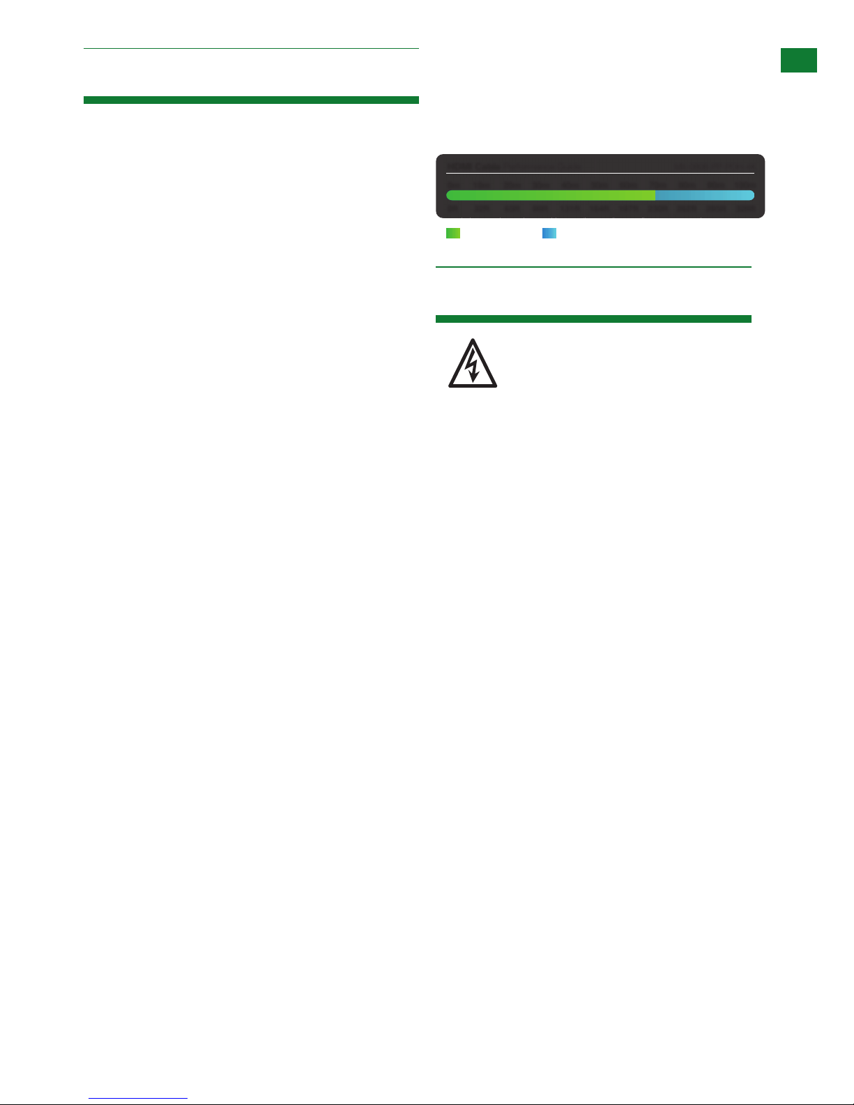
HDMI Cable Performance Guide
MX-0808-PP-POH-4K
0ft 328ft32ft 65ft 98ft 131ft 164ft 197ft 230ft 262ft 295ft
0m 100m
10m
20m 30m 40m 50m 60m 70m 80m 90m
4K Transmission HD Transmission

4
Technical Support: support@wyrestorm.com US: +1 866 677 0053 EU: +44 (0) 1793 230 343
PACKAGE CONTENTS AND SPECIFICATIONS
4. Package Contents
5. Specication
1 x MX-0808-PP-POH-4K main chassis unit
1 x Printed instruction manual
1 x Flash memory USB stick containing PC control software and
digital copy of instruction manual (digital version downloadable
from product page)
8 x IR Receivers (30KHz to 50KHz)
8 x IR Emitters (For source devices)
1 x IR RX extension cable (38KHz for local IR control)
1 x 100-240v AC power supply
1 x USB to Serial cable
1 x pair matrix mounting brackets
I/O Connections 8 x HDMI IN
8 x HDBT OUT
8 x HDMI OUT
8 x IR RX
8 x IR TX
1 x IR Extension
1 x EDID DIP Switch
1 x Ethernet
1 x LAN
1 x RS232
1 x RS485
Output Bandwidth Signaling Rate 6.75Gbps
Input video Signal 0.5-1.0 volts p-p
Input DDC Signal 5 volts p-p (TTL)
Maximum Pixel Clock 297MHz
Video Impedence 100 Ω
Power Supply AC 100~240V 50/60Hz
Power Consumption 180W Max
BTU Rating 614
Video Format Supported 480i, 576i, 480p, 576p, 720p, 1080i, 1080p @ up to 60Hz
3840x2160 @ 30Hz, 4096 x 2160 @ 30Hz
Audio Format Supported Stereo, LPCM 5.1, LPCM 7.1, Dolby True HD, DTS-HD Master Audio
Output Video HDMI 1.4 with HDCP + full 3D
Storage Temperature -4°F to 140°F (-20°C to 70°C) 10% to 90%, non-condensing
Control Method IR control
Front panel buttons
RS232
RS485
LAN
Operating Temperature 32°F to 95°F (0°C to 35°C) 10% to 90%, non-condensing
Storage Temperature -4°F to 140°F (-20°C to 70°C) 10% to 90%, non-condensing
ESD Protection ±8kV (air-gap discharge) ±4kV (contact discharge)
Surge Protection Voltage: ±1kV
Technical
5
Technical Support: support@wyrestorm.com US: +1 866 677 0053 EU: +44 (0) 1793 230 343
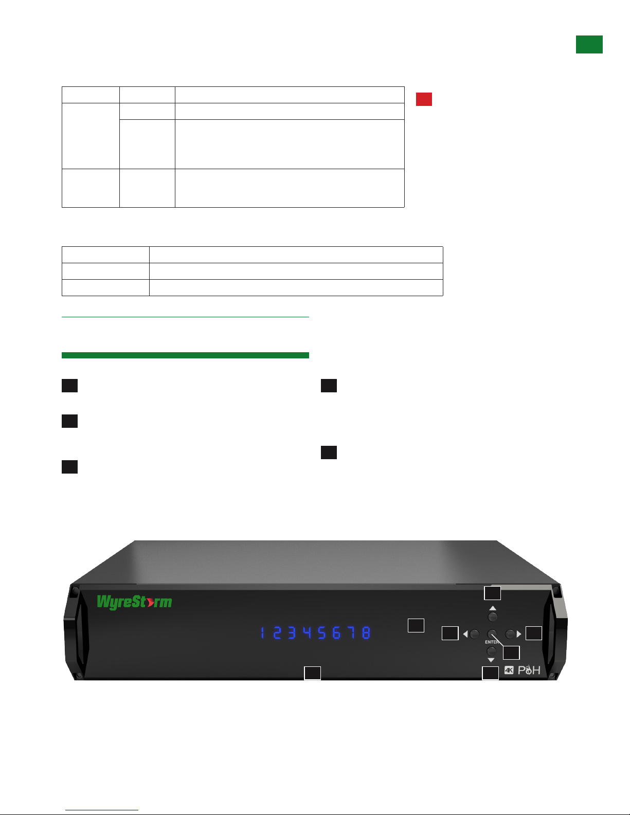
6. Front Panel Description
FRONT PANEL DESCRIPTION
1
LED input/output select screen - Displays matrix
switching status for each connected input/output
4
Output select buttons (left/right) - Selects output using
the left /right selection button - Press ENTER to conrm
selection
Note: Selection will not be made unless Enter is
pressed
2
IR receive window - Receives control signals from IR
control handset (accepts commands for this
model matrix only)
5
Enter - Press to conrm input/output selection
3
Input select buttons (UP/DOWN) - Selects input source
by pressing up/down selection - Press ENTER to conrm
selection
Note: Selection will not be made unless Enter is
pressed
Cable Type Range Supported Video
Cat5e/6 100m/328ft 1080p @ 60Hz / 36bit Deep Colour
70m/230ft 1080p @ 60Hz / 48bit Deep Colour
1080p @ 60Hz 3D
4Kx2K @ 30Hz / 4:2:2 chroma sub-sampling
Cat6a/7 100m/328ft 1080p @ 60Hz / 48bit Deep Colour
1080p @ 60Hz 3D
4Kx2K @ 30Hz / 4:2:2 chroma sub-sampling
Cable Specications
NOTE: Cable types below are for reference only. It is strongly recommended that you use the cables recommended by HDBaseT.
WyreStorm suggest the use of straight-through Ethernet cables terminated to T568B standards.
Dimensions (WxHxD) 438mm x 87.7mm x 396mm / 17.2’’ x 3.5’’ x 15.6’’
Mass (Main unit) 7.46kg / 16.45lbs
Certiication CE, FCC, RoHS
General
2
3
3
4
5
4
1
Please note cable type,
range and supported video
limitations. Successful
transmission may not be
achievable with cable or
distances other than those
specified. Please ensure cable
distance does not exceed
stated range.
!
6
Technical Support: support@wyrestorm.com US: +1 866 677 0053 EU: +44 (0) 1793 230 343
REAR PANEL DESCRIPTION
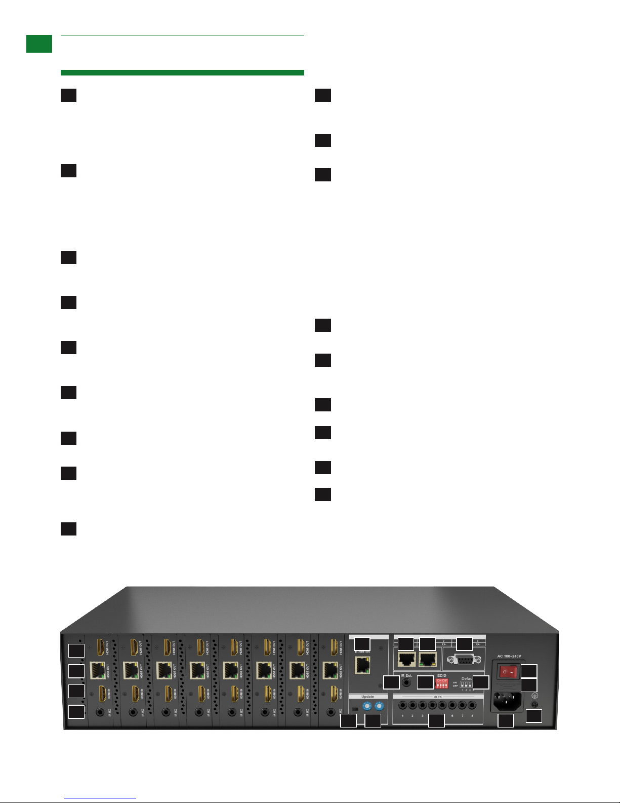
7. Rear Panel Description
1
Mirrored HDMI OUT ports 1~8 (From left to right) Mirrored to HDBaseT output, connects to the local HDMI
devices with HDMI or DVI to HDMI cables.
NOTE: this port supports up to 1080p resolution only.
A 4K source cannot be duplicated
2
HDBaseT OUT ports 1~8 (From left to right) - Connects to
HDBT IN ports of compatible HDBaseT Receivers (such
as RX-70-4K) with single Cat5e/6 cable for transmission
of HDMI Audio/Video, IR, RS232, Ethernet and 100W
power.
NOTE: HDMI OUT has higher priority over HDBT OUT
if both are connected.
3
HDMI IN ports 1~8 (left to right) - Connects to the local
HDMI source devices with HDMI cables or DVI to HDMI
cables.
4
IR RX Receiver ports 1~8 (left to right) - Connects to the
supplied broadband IR receivers for IR signal reception to
control the IR devices remotely from the matrix side.
5
Ethernet port - Connects to an active IP network to share
network access with any of the eight Ethernet equipped
devices at the HDBaseT end.
6
RS485 port - Connects to a RS485 device, such as a PC
or control system device, with a RJ45 to RS485 converter
and a serial cable for matrix control.
7
LAN port - Connects to an active IP network for control
of matrix via LAN (Telnet & Web GUI).
8
RS232 port - Connect to a RS232 device, such as a
PC or control system device, with the supplied USB to
UART cable or a direct serial cable for matrix control or
rmware upgrading.
9
IR Ext. port - Connects to a supplied IR receiver (not
broadband cable) for IR signal reception to locally control
the matrix.
10
EDID DIP switch - Manual DIP setting for EDID
management for improved device connection
compatibility. (See EDID section for settings)
11
EDID DIP switch default setting diagram - Default factory
setting reference
13
Firmware Upgrade DIP switches - DIP settings to update
transmission card rmware.
14
IR TX ports 1~8 - Connects to the supplied IR emitters
for IR signal transmission to control the IR devices
remotely from the sink side.
15
Power switch - Powers matrix on/o
16
Fuse - To prevent voltage/current excess that can
damage circuitry. Lift cover to replace fuse
17
Power - AC 100~240V 50/60Hz power input.
18
GND - Electrical grounding to prevent static build up
12
Update mode switch
• Left position for Normal mode (default) – Normal
matrix function including RS232 control.
Note: Matrix software cannot be updated in this
setting.
• Right position for Update mode – normal matrix
function without RS232 control functionality. RS232
required for rmware update.
Note: Ensure switch is returned to the left
‘Normal’ mode after updating for full RS232 control
functionality.
RS232 cable required for rmware update.
2
3
5 6 7 8
9 10 11
12 13 14
15
16
17
18
4
1
7
Technical Support: support@wyrestorm.com US: +1 866 677 0053 EU: +44 (0) 1793 230 343
8. Connection & Operation
CONNECTION & OPERATION
The matrix allows any eight input channels (HDMI) to be
routed to any eight output channels (HDBaseT or HDMI),
regardless of source HDCP status, with HDMI OUT (up
to 1080p) a higher output priority over HDBT OUT (up to
4Kx2K) if both are connected.
NOTES BEFORE INSTALLATION:
• Please be mindful of cable type and distance limitations
stated in Specification (Section 5 of this manual) 4K:
70m/230ft 1080p: 100m/328ft
• PoH functionality of the matrix is designed for powering
compatible HDBaseT RX-70-4K receiver units only. NonPoH receivers will require their own local power supply.
Non-WyreStorm display receivers may not be compatible
with this matrix product
• Use of straight-through Ethernet cables wired to
T568B standards is advised to achieve best results as
recommended by HDBaseT
• Connect/disconnect all cables gently during installation
and ensure power supplies are disconnected from all
devices before installation
• Ensure that any 4K sources and 4K display devices
used are compatible and outputting the correct
resolutions for EDID to be successfully negotiated and
signals received.
NOTE Both 4K and 1080p HD sources and displays
may be contained within the same distribution–
to combine 4K and HD sources and displays a
WyreStorm EXP-SCL-DAC-4K to HD/HD to 4K
scaler must be used between connected HDMI
display device
Visit wyrestorm.com for more information on 4K/HD
scaling and Dolby downmixing.
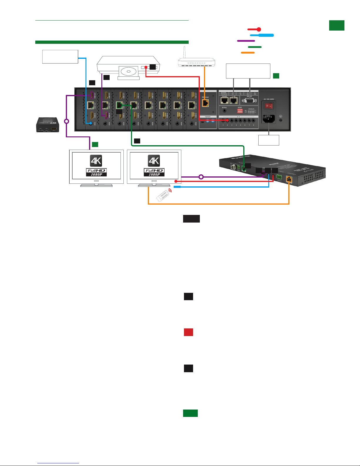
CONNECTION:
Connect source devices (such as: Blu-ray, computer,
games console, satellite/cable, music streaming device,
CCTV etc.) to the relevant input ports of the matrix output
modules 1-8.
Do Not Hotswap HDMI plugs or HDBaseT
connectors – Insert/extract cables carefully with
devices and mains SWITCHED OFF to avoid power
passed over the cable damaging circuitry.
For IR control of sources from a display zone,
connect an IR transmitter from the matrix to each source,
ensuring the IR emitter is attached directly over the
infrared receiving area of the device, using the adhesive
backing to secure in place.
HINT Locate the infrared sensor on devices by shining a
flashlight onto the display panel of sources and look for a
small sensor.
1
2
!
RX-70-4K
4K Source Device
Display 1 Mirror
Duplicate HDMI
IR receiver and IR emitter placed discretely on the
display with a clear line of sight to the remote handset
being used
IR emitter placed securely over
input device infrared sensor window
Power
LAN / Serial based
Control System
CAB-IR-LINK Cable
connecting from Control
System to IR RX port of
matrix
4K: 70m/230ft 1080p: 100m/328ft
Display 1
Control
System
Wi Router
1
1
2
5
5
3
726
4
8
Connection
KEY
IRTX Emitter
IRRX Receiver
HDMI
optional
IR Emitter
IR Receiver
HDMI
UTP Cat5e/6
Ethernet
Connection
Control System
LANRS485
optional
RX RX
1
1
2
11. Basic Remote Control
OUTPUT
CHANNEL
INPUT SELECT
1
2
3
4
5
6
7
8
To change handset battery
Pinch here and pull out
Install battery ‘+’ side
up and only use CR
2025 3V batteries. Slide
compartment back into
OUTPUT
CHANNEL
INPUT SELECT
1
2
3
4
5
6
7
8
The default system setting is 0x00 to control one matrix, but
pressing the SYSTEM CODE button on the handset THREE
TIMES rapidly activates the alternative Matrix SYSTEM CODE
0x4e, allowing independent control of a second unit. Pressing the
button three times again to reverts back to default 0x00 setting.
Optional
EXP-SCL-DAC-4K
4K/HD Scaler
Optional
EXP-SCL-DAC-4K
4K/HD Scaler

8
Technical Support: support@wyrestorm.com US: +1 866 677 0053 EU: +44 (0) 1793 230 343
5
7
6
8
9
CONNECTION & OPERATION
Adjustment of the IR emitter position after installation
may be required to achieve the best results as moving
to different areas of the source fascia can improve IR
performance.
Plug the 3.5mm jack of the IR emitter into the
corresponding number IR TX port on the rear panel of the
MATRIX.
NOTE HDMI output supports up to 1080p only. 4K
source cannot be duplicated. EXP-SCL-DAC-4K
scaler is required to scale up the 1080p signal for
connection to a local 4K screen
For two-way IR control of display from source
location:
i. Connect a WyreStorm IR link cable (CAB-IR-LINK)
between the IR RX port on the matrix output modules to a
control system.
or
ii. Connect 3.5mm jack of the IR receiver into the
corresponding IR RX port on matrix output cards,
ensuring the IR receiver eye is placed in clear view to
receive an IR signal from the handset to be used to
control.
Connect a good quality, well-terminated Cat 5e/6/7
cable with an RJ45 connector wired to 568B standard
at both ends from the HDBaseT Output port of matrix
transmission cards the UTP IN of the RX-70-4K display
receiver. *
* Please be mindful of cable type, transmission
range and 4K or HD support as stated in
Specification (Section 5 of this manual)
NOTE Although all WyreStorm products are tested
using Cat5e as standard, we suggest using Cat6 as
the preferred cable due to its improved transmission
capabilities.
Ensure both RJ45 connectors are pushed securely
into each port and supported by the connector strain relief
clip to prevent loosening.
If using a WyreStorm extender set, connect the
transmitter device to the matrix via the HDMI port and
connect to the RX-70-4K receiver via Cat5e/6/7.
NOTE No power supply is required to the RX-70-4K
if connected from the MX-0808-PP-POH-4K matrix
or other PoH-enabled transmission device.
The 12v power input on the display receiver is
optional, and should be used only if there is
insufficient power from the transmission device.
Power is passed along the Cat5e/6/7 cable so
the quality of termination, cable and condition are
essential for successful delivery of video, audio,
control and power to receivers.
Poor quality terminations lead to intermittent
performance and longer install times.
PoH functionality will not be possible if using a nonPoH enabled Receiver.
Sudden movement of the matrix and receivers could
lead to loss of picture and sound if connections
become loose or strained, resulting in unnecessary
service call-backs. We strongly recommend using
the mounting brackets supplied to secure devices.
Connect HDMI OUT of the RX-70-4K to the HDMI IN
of the display device.
Plug the 3.5mm jack of the IR receiver into the IR RX
port of the display receiver.
Place the IR receiver discretely on the front of the display
with care taken to achieve a clear line of sight with the
remote control to be used.
For two-way IR controlling the display from the matrix
end: Plug the 3.5mm jack of the IR emitter into the IR TX
port on the display receiver, ensuring the emitter is placed
directly over the infrared receiving sensor of the display
using the adhesive backing.
Again, adjustment of receiver and emitter position may be
needed to achieve the best IR signal distribution.
Switch on the power to your input sources, displays,
and any display receivers used.
All receivers must be connected to the matrix
via UTP cable before matrix is powered on.
As power forms part of the HDBaseT carrier
signal, if a transmission link can not be established
between matrix and display receiver, it is unlikely
the receiver will be able to draw power.
Should such problems be experienced between
transmission and receiving device, investigate the
root cause of the issue by following the checklist in
the Troubleshooting section of this guide.
Finally, switch on the matrix at the rear and your
WyreStorm system should now be fully connected and
ready for use.
If IR transmitters and receivers are correctly placed
discrete control of both sources and displays will be
possible from either location.
4
3
!
!
9
Technical Support: support@wyrestorm.com US: +1 866 677 0053 EU: +44 (0) 1793 230 343
9. Front Panel Control
FRONT PANEL CONTROL
!
Remember, always switch off the matrix before
unplugging any inputs or outputs – follow last on,
first off protocol.
OPTIONAL CONNECTION:
If using a duplicate display or AVR mirrored to the
HDBaseT Output, connect the display via the HDMI OUT
port of the transmission card
NOTE HDMI output supports up to 1080p only. 4K
source cannot be duplicated.
For control system integration, connect additional
RJ45 terminated category cable or RS232 serial cable.
See section 11 - RS232 Control for more details
Combined 4K and HD Distribution
If your distribution contains both 4K and 1080p sources
and displays, the matrix will search for the most
compatible EDID screen resolution between all connected
devices, (typically the highest resolution ALL displays
can support), which will in most cases result in resolution
disparity and automatic downscaling 4K content to 1080p
across all screens.
To maintain 4K resolutions to 4K screens in distributions
containing lower resolution legacy displays, a WyreStorm
EXP-SCL-DAC-4K scaler and Dolby downmixer should
be used inline between HDMI devices to scale down 4K
transmissions to 1080p HD 24fps, upscale 1080p HD to
4K at 30Hz or allow signal pass-through.
Furthermore, Dolby downmixing to stereo PCM enables
multichannel audio up to 5.1 to be distributed to zones
that can support it and automatically scaled down to
compatible stereo PCM for those that cannot without
sacrificing the integrity of the distribution.
Visit wyrestorm.com for more information on 4K/HD
scaling and Dolby downmixing.
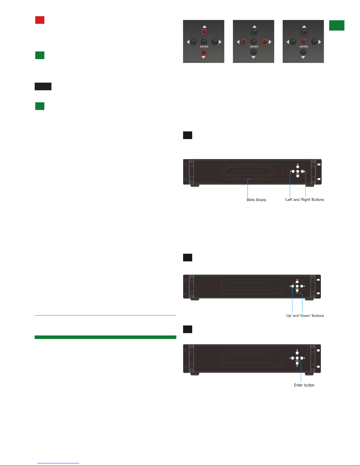
The matrix is designed with ease of connection and
control in mind with basic switching of source inputs to
output displays achieved via the front panel control of the
matrix and the front LED screen displaying the current
input and output status of the matrix.
On power up, the front panel will flash as the matrix
initialises. When the display stops flashing, the matrix is
ready to use.
OUTPUTS are selected by pressing the LEFT and
RIGHT arrow buttons to scroll forwards and backwards
numerically through the displays connected to the matrix.
The corresponding OUTPUT channel number will blink on
the display when reached.
Press the LEFT ARROW or RIGHT ARROW key to
select an output. After the selection is complete, the
corresponding LED indicator blinks.
Likewise, the UP and DOWN arrow buttons scroll
numerically through any INPUT sources connected to
the system. When the desired OUTPUT and INPUT is
reached, push the ENTER button to confirm the selection.
The display will stop blinking to confirm the matrix has
been set.
Press the UP ARROW or DOWN ARROW key to
select an input.
Press the ENTER key to confirm the selection. After
the selection takes effect, the LED stops blinking.
Repeated pressing of the select button of a specific
output scrolls numerically through the HDMI input devices
connected to the matrix, with the corresponding LEDs
illustrating when a device has been selected for that
OUTPUT
selection
INPUT
selection
Confirm
OUTPUT/INPUT
1
2
2
3
1
10
Technical Support: support@wyrestorm.com US: +1 866 677 0053 EU: +44 (0) 1793 230 343
particular output. The chosen input will automatically store
for the output so, even when the matrix is powered off
and on, the last selected input/output combination will
remain.
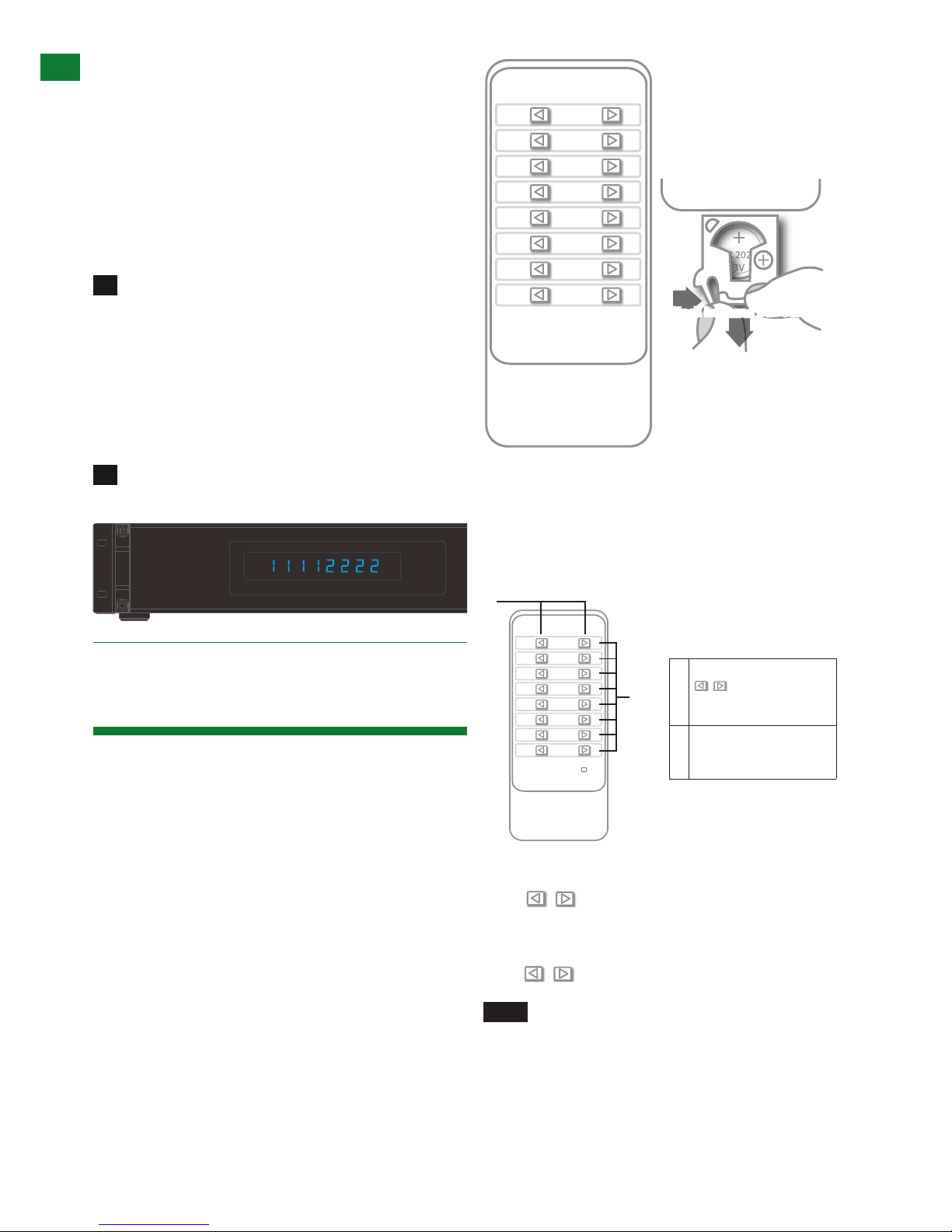
Example
If outputs 1-4 need to be set to input 1 and outputs
5-8 need to be set to input 2, the following sequence of
button presses need to be performed.
To switch output/input selection:
Set the output 1 to the input 1.
i. Press left/right selection button to highlight the Output
1. LED blinks slowly to indicate the output has been
chosen.
ii. Press up/down selection button to switch that Output
to Input 1.
iii. Press Enter button for the selection take effect. LED
stops blinking to indicate the operation is successful and
the Output has been set to the chosen input.
Repeat steps above to perform the other output/
input selections. The final configuration is as follows.
The same basic switching functions can also be accessed
via the remote control.
Simply toggle through the INPUT sources connected to
the matrix by pressing the left/right arrow buttons in each
numbered OUTPUT section on the handset.
Operation of the handset is the same regardless of
location – locally (source/matrix location - IR TX) or
Remotely (display location - IR RX).
Note:
• Ensure IR receivers and IR emitters are fully
connected to correct matrix ports and placed in clear
view to receive IR signals from the remote (IR RX) and
transmit signals to the matrix (IR TX)
• The remote handset must be pointed directly at the
IR receiver window on the matrix fascia or the IR RX
Extension receiver eye for signals to be received by
the matrix.
i) Matrix Control at Matrix Location (Local)
Local control of the matrix from the matrix location is
achieved by sending IR command signals to the IR
receiver window on the matrix or IR RX Extension receiver
connected to the IR Ext. port at the rear of the matrix.
When using the matrix remote locally, point the handset
directly at the matrix or IR RX extension receiver and
press are used to scroll between the connected
input sources for each individual output display. For
example, to select output display 1 to be set to input
source 2, find row 1 on the matrix control handset and
scroll to input source 2.
NOTE Ensure IR emitters are securely placed
over source IR sensor windows. You can locate
IR sensors on devices by shining a flashlight onto
the fascia – the sensor should be visible as a small
round diode behind the device panel.
BASIC RE MOTE CONTROL
System Code Switch
INPUT SELECT
BASIC RE MOTE CONTROL
System Code Switch
INPUT SELECT
BASIC RE MOTE CONTROL
BASIC RE MOTE CONTROL
BASIC RE MOTE CONTROL
OUTPUT
CHANNEL
INPUT SELECT
1
2
3
4
5
6
7
8
To change handset battery
Pinch here and pull out
Install battery ‘+’ side
up and only use CR
2025 3V batteries. Slide
compartment back into
the handset.
OUTPUT
CHANNEL
INPUT SELECT
1
2
3
4
5
6
7
8
System Code Switch
The default system setting is 0x00 to control one matrix, but
pressing the SYSTEM CODE button on the handset THREE
TIMES rapidly activates the alternative Matrix SYSTEM CODE
0x4e, allowing independent control of a second unit. Pressing the
button three times again to reverts back to default 0x00 setting.
NOTE
Changing the System Code is only necessary if you
are using two identical units within close range of the IR
signal. If using in different parts of the same room it is likely
that you will not need to change the setting.
HINT
If your remote control is not working, before changing the
battery, try changing the System Code on the handset in case it
has accidentally been switched to an alternative matrix control
mode.
Remote Control at the Display End (Remote IR)
When controlling the matrix remotely from the display side, the
1
2
BASIC REM OTE CONTROL
System Code Switch
INPUT SELECT
BASIC REM OTE CONTROL
1 Previous and next buttons
Scrolls between Input
sources
2 Rows 1~8 represent
Outputs ports for Input
selection
MATRIX IR REMOTE CONTROL
BASIC REMOTE CONTROL
OUTPUT
CHANNEL
INPUT SELECT
1
2
3
4
5
6
7
8
To change handset battery
Pinch here and pull out
Install battery ‘+’ side
up and only use CR
2025 3V batteries. Slide
compartment back into
the handset.
OUTPUT
CHANNEL
INPUT SELECT
1
2
3
4
5
6
7
8
System Code Switch
The default system setting is 0x00 to control one matrix, but
pressing the SYSTEM CODE button on the handset THREE
TIMES rapidly activates the alternative Matrix SYSTEM CODE
0x4e, allowing independent control of a second unit. Pressing the
button three times again to reverts back to default 0x00 setting.
NOTE
Changing the System Code is only necessary if you
are using two identical units within close range of the IR
signal. If using in different parts of the same room it is likely
that you will not need to change the setting.
HINT
If your remote control is not working, before changing the
battery, try changing the System Code on the handset in case it
has accidentally been switched to an alternative matrix control
mode.
Remote Control at the Display End (Remote IR)
When controlling the matrix remotely from the display side, the
Install battery ‘+’ side up
and only use a CR2025 3v
battery. Slide compartment
back into the handset.
10. Matrix IR Remote
Control
2
1
 Loading...