

Wyrestorm MX-0404-HDBT-H2A-KIT Quick Start Manual
4x4 4K UHD HDBaseT (35m/115ft) Matrix with audio breakout,
HDCP 2.2 and PoH Receivers
MX-0404-HDBT-H2A-KIT
Quickstart Guide
IMPORTANT! Installation Requirements
• Visit the product page to download the latest rmware, document
version, additional documentation, and conguration tools.
• Install the latest rmware (if available) to ensure that all features
described in this document are available during and after installation.
• Read through the Wiring and Connections section for important wiring
guidelines before creating or choosing premade cables.
In the Box
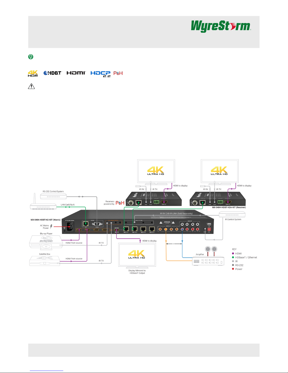
1 x MX-0404-HDBT-H2A HDBaseT Matrix Switcher
4 x HDBaseT PoC display receivers
1 x Handheld IR Remote
4 x IR emitters
4 x IR Broadband Receiver (30KHz to 50KHz)
1 x IR Extension Cable
1x AC Power Cord with US Plug
1x AC Power Cord with UK Plug
1x AC Power Cord with EU Plug
2x Mounting Brackets and accessories (matrix)
1x Quickstart Guide
Basic Wiring Diagram
Copyright © 2017 WyreStorm Technologies | wyrestorm.com
MX-0404-HDBT-H2A-KIT Quickstart Guide | 170725
UK: +44 (0) 1793 230 343 | ROW: 844.280.WYRE (9973)
support@wyrestorm.com
1 of 4
WyreStorm recommends reading through this document in its entirety to become familiar with the product’s features prior to starting the installation
process.
Wiring and Connections
WyreStorm recommends that all wiring for the installation is run and terminated prior to making connections to the switcher. Read through this section in this
entirety before running or terminating the wires to ensure proper operation and to avoid damaging equipment.
HDMI/HDBaseT Wiring
IMPORTANT! Wiring Guidelines
• The use of patch panels, wall plates, cable extenders, kinks in cables, and
electrical or environmental interference will have an adverse effect on HDMI
and Ethernet transmission limiting performance. Steps should be taken to
minimize or remove these factors completely during installation for best
results.
• WyreStorm recommends using high quality HDMI cables such as
WyreStorm Express to ensure the highest content performance available.
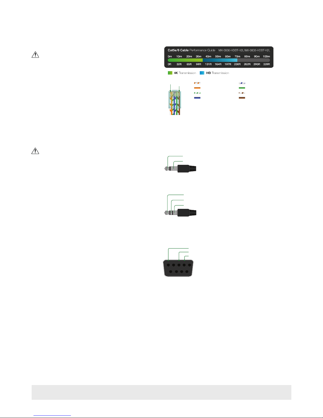
• The type of category cable and length used can restrict the available video
resolution. While Cat5e can be used, WyreStorm recommends using Cat6
or higher to ensure the highest content performance available. See Video
Resolutions in the Specications table before determining cable type and
length.
Pin 1
Pin 8
Wire colors shown follow EIA/TIA-568B standard.
Pin 1:
Pin 2:
Pin 3:
Pin 4:
Pin 5:
Pin 6:
Pin 7:
Pin 8:
White/Orange
Orange
White/Green
Blue
White/Blue
Green
White/Brown
Brown
IR TX/RX Wiring
IMPORTANT! IR TX/RX Guidelines
• WyreStorm IR ports function differently than standard IR ports. For this
reason only WyreStorm IR emitters and receivers can be used.
• WyreStorm IR emitter and receiver cables cannot be spliced as cutting
into the cables will short the shield. While an extension cable may be used,
WyreStorm assumes no responsibility for operation using an extension
cable.
• When connecting the IR TX to an IR connecting blocks or control system
with different plugs, a cable must be made following the IR TX Port Pinout
diagram.
• When connecting to an IR control system use the WyreStorm CAB-IR-LINK
cable. This cable compensates for differences between the WyreStorm
RX and the control systems TX connection. Visit the CAB-IR-LINK product
page for details.
IR TX Port Pinout
Tip: Anode/5V
Sleeve: Cathode/IR Signal
IR RX/Ext Port Pinout
Tip:
Ring: IR Signal
+5V DC
Sleeve: Ground (GND)
RS-232 Wiring
Most control systems and computers are DTE where pin 2 is RX, this can vary
from device to device. Refer to the documentation for the connected device
for pin functionally to ensure that the correct connections can be made.
5
9 8 7 6
4 3 2 1
Outside of DB9 chassis port shown.
Unidnetified pins have no function and should
Pin 3: RX (Receive)
Pin 2: TX (Transmit)
Pin 5: GND (Ground)
Copyright © 2017 WyreStorm Technologies | wyrestorm.com
MX-0404-HDBT-H2A-KIT Quickstart Guide | 170725
UK: +44 (0) 1793 230 343 | ROW: 844.280.WYRE (9973)
support@wyrestorm.com
2 of 4
 Loading...