

Wyott Y32HH Installation Manual
R
INSTALLATION AND OPERATING INSTRUCTIONS
HOT WELL TABLES
Models: Y46HHH, Y32HH, YTS1 & Y60HC
Y46HHH
YTS1
WARNING: Improper installation, operation, service or maintenance can cause
property damage, injury or death. Utility location is CRITICAL. Read and understand
!
these instructions thoroughly before positioning, installing, maintaining or servicing
this equipment.
Y32HH
Y60HC
!
P/N 8806304 9/05
APW WYOTT Foodservice Equipment Company
P.O. Box 1829
Cheyenne, WY 82003
+1 (307) 634-5801 Phone +1 (800) 752-0863 Toll Free
+1 (307) 637-8071 Fax www.apwwyott.com
1
GENERAL INFORMATION
THIS MANUAL SHOULD BE RETAINED FOR FUTURE REFERENCE
Congratulations on your purchase ofAPW Wyott Modular Assembly Pack Station. APW Wyott takes pride
in the design and quality of our products. When used as intended and with proper care and maintenance,
you will experience years of reliable operation from this equipment. To ensure best results, it is important
that you read and follow the instructions in this manual carefully.
Before installing and operating this equipment be sure everyone involved in this operation is fully trained
and is aware of all precautions. Accidents and problems can result by a failure to follow fundamental rules
and precautions.
The following words and symbols, found in this manual, alert you to the hazards to the operator, service
personnel or the equipment. The wordsare defined as follows.
WARNING: This symbolrefers to a potential hazard or unsafe practice, which could result
in serious injury or death.
!
CAUTION: This symbol refers to a potential hazard or unsafe practice, whichmay result in
minor or moderate injury or product or property damage.
!
NOTICE: This symbol refers to information that needs special attention or must be fully
understood even though not dangerous.
!
!
!
!
SAFETY PRECAUTIONS
CAUTION: These models are designed, built, and sold for commercial use. If these
models are positioned so the general public can use the equipment make sure that
cautions, warnings, and operating instructions are clearly posted near each unit so that
!
anyone using the equipment will use it correctly and not injure themselves or harm the
equipment.
IMPORTANT: We strongly recommend having a licensed electrician install this
equipment. The electrician should be familiar with all local and national codes.
!
WARNING: Check the data plate on this unit before installation. Connect the unit only to
the voltage and frequency listed on the data plate. Connect only to 1 or 3 phase as listed on
!
the data plate.
WARNING: Electrical and grounding connections must comply with the applicable
portions of the national electrical code and/or other local electrical codes.
!
WARNING: Disconnect device from electrical power supply and place a Tag Out-Lockout
on the power plug, indicating that you are working on the circuit.
!
!
!
!
!
!
WARNING:Afactory authorized agent should handle all maintenance and repair. Before
!
doing any maintenance or repair, contactAPW Wyott.
WARNING: An earthing cable must connect the appliance to all other units in the
!
complete installation and from there to an independent earth connection.
2
!
!
NOTICE: This productis intended for commercial use only.Not for household use.
!
WARNING:SHOCK HAZARD: Do not open any panels that require the use of tools.
!
WARNING: Improper installation, adjustment, alteration, service or maintenance can
cause property damage, injury or death. Read installation, operating and maintenance
!
instructions thoroughly before installing or servicingthis equipment.
NOTICE: The unit when installed, must be electrically grounded and comply with local
codes, or in the absence of local codes, with the national electrical code ANSI/NFPA70latest edition. Canadian installation must comply with CSA-STANDARD C.22.2 Number0
!
M1982 General Requirements-Canadian Electrical Code Part II, 109-M1981Commercial CookingAppliances.
NOTICE: Local codes regarding installation vary greatly from one area to another. The
National Fire Protection Association, Inc. states in its NFPA96 latest edition that local
!
codes are “Authority Having Jurisdiction” when it comes to requirement for installation of
equipment. Therefore, installation shouldcomply with all local codes.
!
!
!
!
!
SECTION
1
2
3
4
5
6
TABLE OF CONTENTS
ITEM
General Information
Safety Precautions
Installation Check List
Installation
Electrical Wiring
Operation & Maintenance
A Initial Cleaning
B Cleaning
C Maintenance
Troubleshooting Chart
Specifications
A Y46HHH
B Y32HH
C YTS1
D YDS5
PAGE
2
2
4
4
6
11
11
11
12
13
14
14
15
16
17
Parts Lists & Exploded Views
7
8
Warranty
A
B Y32HH
C YTS1
D YDS5
Y46HHH
3
18
18
19
20
21
24
1. INSTALLATION CHECK LIST
Examine Equipment for Damage
All containers should be examined for damage before and during unloading. The freight carrier has
assumed responsibility for its safe transit and delivery. If equipment is received damaged, eitherapparent or
concealed, a claim must be made with the delivering carrier.
1. Apparent damage or loss must be noted on the freight bill at the time of delivery. The carrier
representative (Driver) the freight bill. If this is not done, the carrier may refuse the
claim. The carriercan supply the necessary forms.
2. Concealed damage or loss if not apparent until after the equipment is uncrated; a request for
inspection must be made to the carrier within 15 days. The carrier should arrange an inspection.
sure to hold all contents and packaging material.
NOTICE: Installation and start-up should be performed by a qualified installer who
!
thoroughly read, understands and followsthese instructions.
NOTICE: If you have questions concerning the installation, operation, maintenance or
service of this product, write Technical Service Department APW WYOTT Foodservice
!
Equipment Company, P.O. Box 1829, Cheyenne, WY 82003.
IMPORTANT: Check Store Layout for Placement and Location of MAPS2 System -Hot
Table, Cold Table, Fries Table, and Toaster Table.
!
must sign
Be
!
!
!
IMPORTANT:Check Store Layout for Placement and Location of Utilities.
!
NOTE: All electrical connections to be hardwired by electrician.
!
!
!
2. INSTALLATION
A qualified installer who thoroughly reads, understands and follows these instructions should perform
installation and start-up.
If you have questions concerning the installation, operation, maintenance or service of this product,
Call: APW Wyott Technical Services Department 1-800-752-0863, ask for Technical Service Department Monday through Friday 9AM 6:30PM Eastern Time.
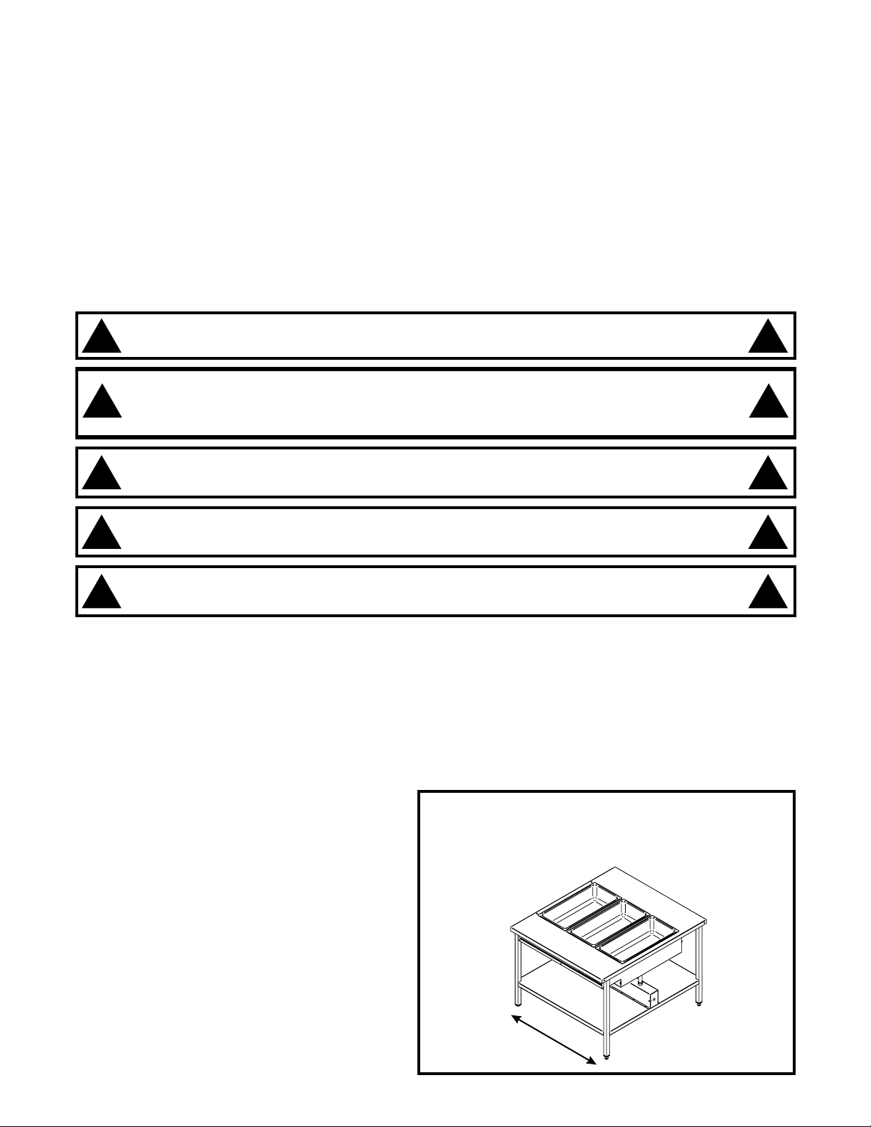
STEP 1. POSITIONTABLE
REVIEW STORE LAYOUT FOR EXACT
LOCATION OFTABLE
Place the over shelf in the designated area.
Level table by using a level and turning the
footpad on theadjustable legs.
Plumbing and electrical wiring must run parallel to,
or under center channel. (It must run in the
direction of arrow)
If table is being used in conjunction with other
tables bolt tables together thru holes in corners
of the top using provided hardware. Make sure
tables all face the same direction (control panels
should be on same side).
4
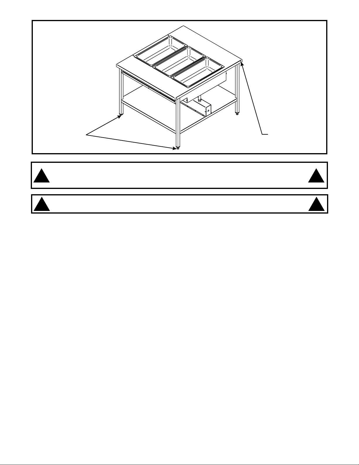
Adjust Legs
WARNING: Check the data plate on this unit before installation. Connect the unit only to
the voltage and frequencylisted on the data plate. Connect only to 1 or 3 phase as listed on
!
the data plate.
WARNING: Electrical and grounding connections must comply with the applicable
portions of the national electrical code and/or other local electrical codes.
!
Holes for bolting
tables together
!
!
5
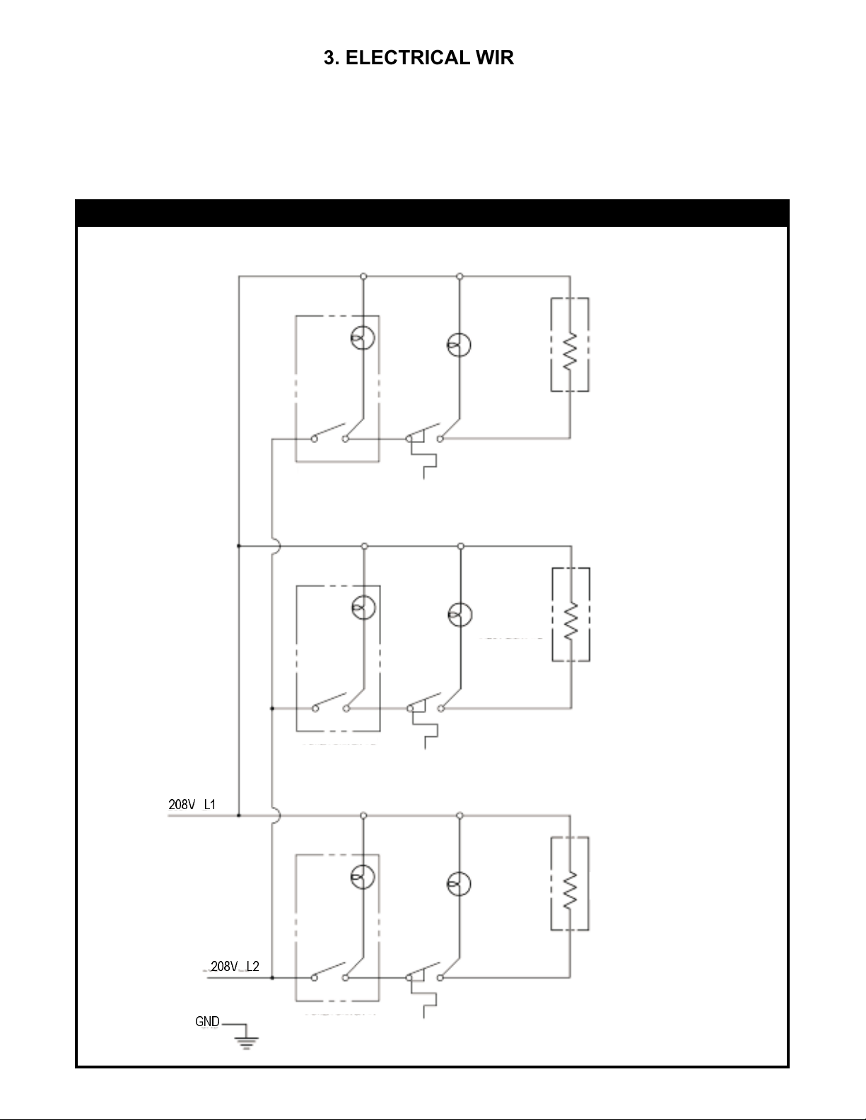
3. ELECTRICAL WIRING
ELECTRICAL CONNECTIONS FOR Y46HHH
Check the data plate to determine what voltage this
unit is wired for and what voltage service is to be used.
SUPPLY REQUIREMENT:
Y46HHH WIRING SCHEMATIC
POWER SWITCH #3
5400W, 208V, 26Amp, 1 Ph
PILOT
LIGHT #3
ELEMENT 1800W
HOTWELL #3
208V L1
GND
208V L2
POWER SWITCH #2
POWER SWITCH #1
PILOT
LIGHT #2
PILOT
LIGHT #1
HOTWELL #2
ELEMENT 1800W
HOTWELL #1
ELEMENT 1800W
6
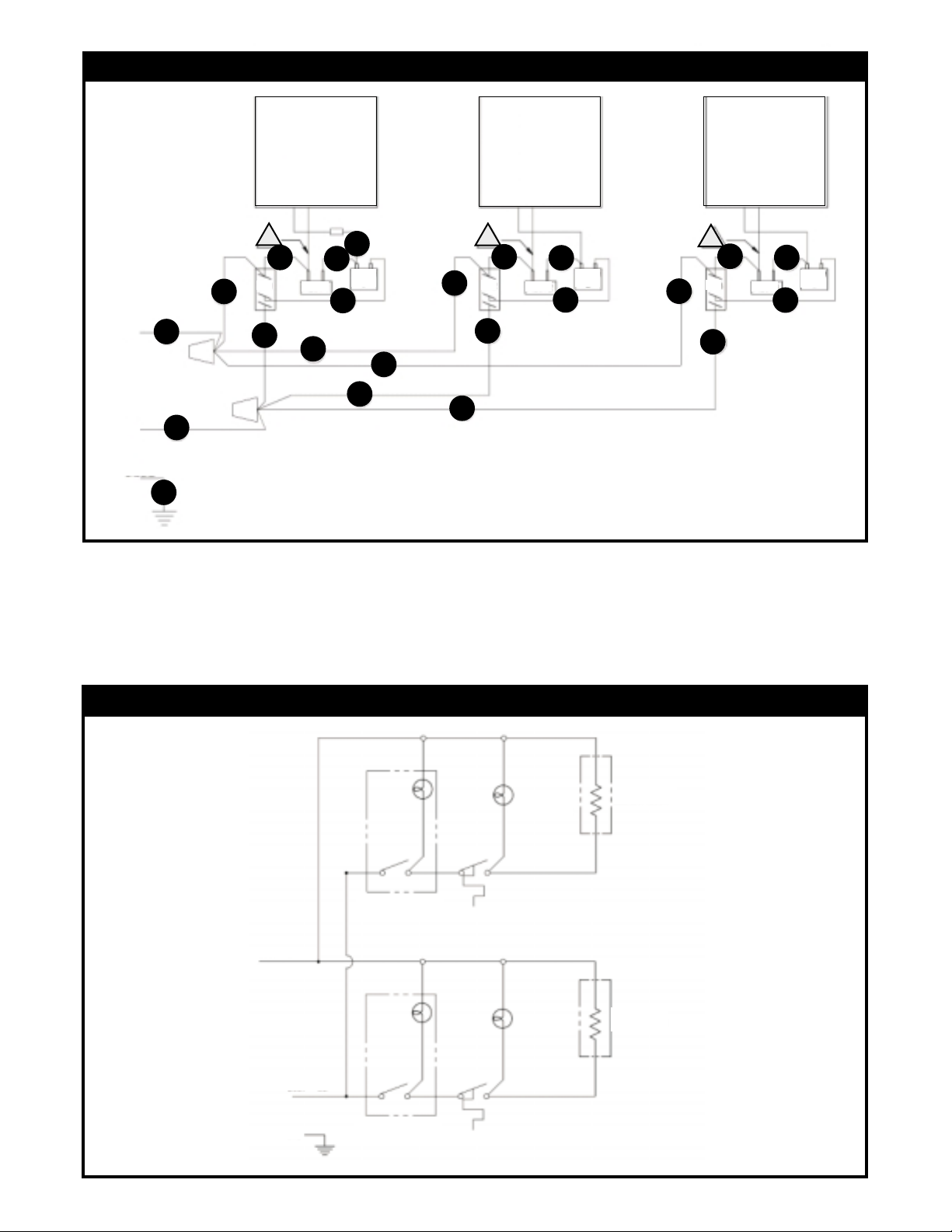
Y46HHH WIRING DIAGRAM
L1
L2
GND
19
17
18
H
O
T
W
E
L
L
1
3
SW 1
1
PILOT 1
6
5
THERM 1
4
2
1
SW 2
7
8
7
H
O
T
W
E
L
L
1
9
PILOT 2
11
10
THERM 2
12
SW 3
13
14
H
O
T
W
E
L
L
PILOT 3
16
THERM 3
15
12
8
13
ELECTRICAL CONNECTIONS FOR Y32HH
Check the data plate to determine what voltage this
unit is wired for and what voltage service is to be used.
SUPPLY REQUIREMENT:
3600 W, 208V, 17.3 Amp, 1 Ph
Y32HH WIRING SCHEMATIC
PILOT
LIGHT #2
POWER
SWITCH #2
208V L1
PILOT
LIGHT #1
ELEMENT 1800W
ELEMENT 1800W
HOTWELL #2
HOTWELL #1
208V L2
GND
POWER
SWITCH #1
7
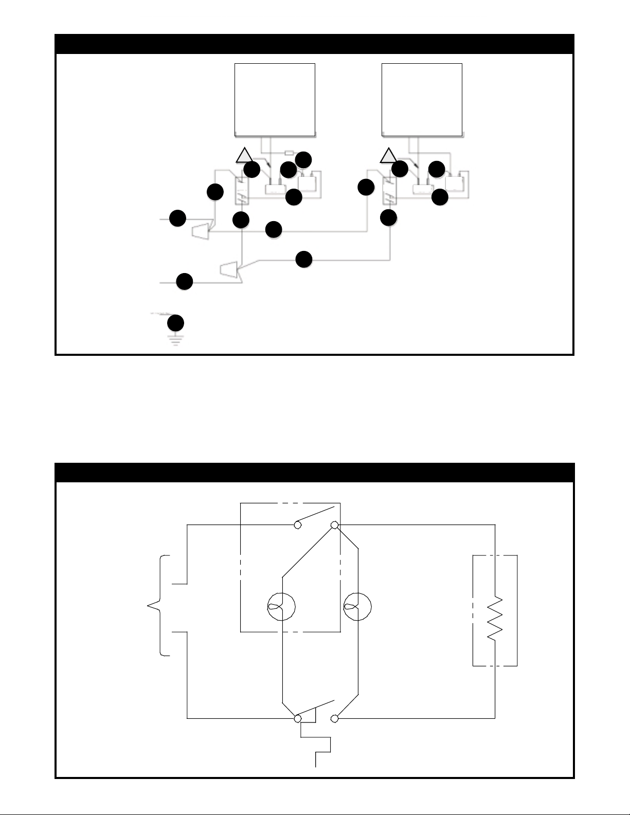
Y32HH WIRING DIAGRAM
L1
L2
GND
14
12
13
H
O
T
W
E
L
L
1
3
SW 1
1
PILOT 1
6
5
THERM 1
SW 2
7
4
2
H
O
T
W
E
L
L
1
9
PILOT 2
11
THERM 2
10
8
7
8
20V15A
CIRCUI T
ELECTRICAL CONNECTIONS FOR YTS1
Check the data plate to determine what voltage this
unit is wired for and what voltage service is to be used.
SUPPLY REQUIREMENT:
YTS1 WIRING SCHEMATIC
POWER S WIT CH # 1
208/240V, 900/1200W, 4.33/5.0 Amp, 1 Ph
HOTWELL #1
ELEMENT
900/1200W
PILOT LIGHT #1
8
 Loading...