

Wyott HCB-2436 Installation Manual
INSTALLATION
AND
OPERATING
INSTRUCTIONS
Heavy Duty Radiant Gas Char-Broilers
MODELS: HCB-2424, HCB-2436, HCB-2448, HCB-2460, HCB-2472
&
Heavy Duty Lavarock Gas Char-Broilers
MODELS: HCRB-2424, HCRB-2436, HCRB-2448, HCRB-2460, HCRB-2472
IMPORTANT FOR FUTURE REFERENCE
Please complete this information and retain this manual for the life of the equipment. For
Warranty Service and/or Parts, this information is required.
Model Number Serial Number Date Purchased
FOR YOUR SAFETY: Do not store or use gasoline or other flammable vapors or liquids
in the vicinity of this or any other appliance.
WARNING: Improper installation, adjustment, alteration, service or maintenance can
cause property damage, injury or death. Read the installation, operating and
maintenance instructions thoroughly before installing, or servicing this equipment.
WARNING: Instructions must be posted in a prominent location. All safety precautions
must be taken in the event the user smells gas. Safety information can be obtained from
your local gas supplier.
GAS-FIRED
U
C
L
US
LISTED
APW Wyott Foodservice Equipment Company
Dallas Plant
729 Third Ave. Dallas, TX 75226
Local: 1-(214) 421-7366
Toll Free: 1-(800) 527-2100
Parts/Service Fax: 1-(214) 565-0976
E-mail: info@apwwyott.com
www.apwwyott.com
U
L
EPH
ANSI/NSF4
P/N 8835300 2-09
Cheyenne Plant
1938 Wyott Drive, Cheyenne, WY 82007
Local: 1-(307) 634-5801
Toll Free: 1-(800) 752-0863
Parts/Service Fax: 1-(307) 772-0460
1

TABLE OF CONTENTS:
ITEM PAGE
Safety Precautions ........................................3
General Installation Instructions....................4
Specifications & Dimensions.........................4
Conversion ....................................................8
Lighting Instructions ......................................9
Operating Instructions ...................................10
CAUTION: These models are designed, built, and sold for commercial use. If these models
are positioned so the general public can use the equipment, make sure that cautions,
warnings, and operating instructions are clearly posted near each unit so that anyone using
the equipment will use it correctly and not injure themselves or harm the equipment.
WARNING: Improper installation, adjustment, alteration, service or maintenance can
cause property damage, injury or death. Read the installation, operating and
maintenance instructions thoroughly before installing, or servicing this equipment.
ITEM PAGE
Cleaning/Maintenance ......................................11
Service/Repair ..................................................12
Troubleshooting Guide......................................12
Replacement Parts Lists & Exploded View.......13
Warranty ...........................................................20
WARNING: For your safety do not store or use gasoline or other flammable vapors and
liquids in the vicinity of this or any other appliance. Keep the area free and clear of
combustibles. (See ANZI Z83. 14B, 1991).
NOTICE: Instructions to be followed if anyone smells gas should be posted in a prominent
place. These may be obtained from the gas supplier.
GAS PRESSURE
The appliance and it’s individual shutoff valve (to be supplied by user) must be disconnected from the gas
supply piping system during any pressure testing of that system at test pressures in excess of ½ psi (3.45
kPa). NOTE: Gas shutoff valve is supplied on CE models.
The appliance must be isolated from the gas supply piping system by closing it’s individual manual shut-off
valve during any pressure testing of the gas supply piping system at test pressures equal to or less than ½
psi (3.45 kPa).
WARNING: A factory authorized agent should handle all maintenance and repair. Before
!
doing any maintenance or repair, contact APW Wyott.
Congratulations on your purchase of APW Wyott commercial cooking or refrigeration equipment.
APW Wyott takes pride in the design and quality of our products. When used as intended and with proper
care and maintenance, you will experience years of reliable operation from this equipment. To ensure best
results, it is important that you read and follow the instructions in this manual carefully.
!
LOCATION OF DATA PLATE
The data plate is located on the right side panel.
2

IMMEDIATELY INSPECT FOR SHIPPING DAMAGE
All containers should be examined for damage before and during unloading. The freight carrier has
assumed responsibility for its safe transit and delivery. If equipment is received damaged, either apparent or
concealed, a claim must be made with the delivering carrier.
A) Apparent damage or loss must be noted on the freight bill at the time of delivery. It must then be signed by
the carrier representative (Driver). If this is not done, the carrier may refuse the claim. The carrier can supply
the necessary forms.
B) Concealed damage or loss if not apparent until after equipment is uncrated, a request for inspection must
be made to the carrier within 15 days. The carrier should arrange an inspection. Be certain to hold all
contents and packaging material.
Installation and start-up should be performed by a qualified installer who thoroughly read, understands and
follows these instruction.
If you have questions concerning the installation, operation, maintenance or service of this product, write
Technical Service Department APW Wyott Foodservice Equipment Company, 1938 Wyott Drive,
Cheyenne, WY 82007.
SAFETY PRECAUTIONS
DANGER: This symbol warns of imminent hazard which will result in serious injury or
death.
WARNING: This symbol refers to a potential hazard or unsafe practice, which could result
in serious injury or death.
CAUTION: This symbol refers to a potential hazard or unsafe practice, which may result in
minor or moderate injury or product or property damage.
NOTICE: This symbol refers to information that needs special attention or must be fully
understood even though not dangerous.
NOTICE: This product is intended for commercial use only. Not for household use.
CAUTION: These models are designed, built, and sold for commercial use. If these
models are positioned so the general public can use the equipment make sure that
cautions, warnings, and operating instructions are clearly posted near each unit so that
anyone using the equipment will use it correctly and not injure themselves or harm the
equipment.
WARNING: Improper installation, operation, service or maintenance can cause property
damage, injury or death. Read and understand these instructions thoroughly before
positioning, installing, maintaining or servicing this equipment.
NOTICE: Local codes regarding installation vary greatly from one area to another. The
National Fire Protection Association, Inc., states in its NFPA96 latest edition that local
codes are “Authority Having Jurisdiction” when it comes to requirement for installation of
equipment. Therefore, installation should comply with all local codes.
3

GENERAL INSTALLATION INSTRUCTIONS
Ensure gas supply and gas type, as shown on unit nameplate agree.
Unit installation must conform with the National Fuel Gas Code, ANSI Z223.1/NFPA 54, the National Gas
Installation Code, CSA-B149.1, or the Propane Installation Code, CSA-B149.2 as applicable and in
accordance with local codes.
Screw legs into the permanently fastened nuts on the four corners of the unit and tighten by hand. Level the
unit by turning the adjustment screw at the bottom of each leg. Do not slide unit with legs mounted, lift if
necessary to move unit.
Pipe threading compound must be resistant to the action of liquefied petroleum gases.
Caution: DO NOT use an open flame to check for leaks. Check all gas piping for leaks with a soap and water
solution before operating unit.
THESE UNITS ARE SUITABLE FOR INSTALLATION ON NON-COMBUSTIBLE SURFACES ONLY.
Noncombustible clearances:
0" sides (0 mm) 0" rear (0 mm) 4” floor (102mm)
Do not obstruct the flow of combustion and ventilation air, under the unit by the legs or behind the unit by the
flue.
Adequate clearance for air openings into the combustion chamber is required. Do not place objects between
the bottom of the unit and the counter top.
There must be adequate clearance for removal of the front panel. All major parts except the burners are
removable thru the front if the gas line is disconnected.
Unit must have adequate clearances for servicing. (Sides = 0”, Rear = 0”, Floor = 4”).
European Community Installation Instructions:
“THIS APPLIANCE MUST BE FITTED BY A COMPETENT PERSON. IN THE UK, CORGI REGISTERED
INSTALLERS (INCLUDING THE REGIONS OF BRITISH GAS) UNDERTAKE TO WORK TO SAFE AND
SATISFACTORY STANDARDS. THIS APPLIANCE MUST BE INSTALLED IN ACCORDANCE WITH THE
GAS SAFETY (INSTALLATION AND USE) REGULATIONS AND THE RELEVANT BUILDING
REGULATIONS / IEE. REGULATIONS. DETAILED RECOMMENDATIONS ARE CONTAINED IN THE
FOLLOWING BRITISH STANDARD CODES OF PRACTICE - BS 6172, BS 5440 PART 2, BS 6891"
"THIS APPLIANCE MUST BE INSTALLED IN ACCORDANCE WITH THE RULES IN FORCE”
"MUST BE INSTALLED IN A WELL VENTILATED AREA. Ventilation requirements ie. B.S. 5440.”
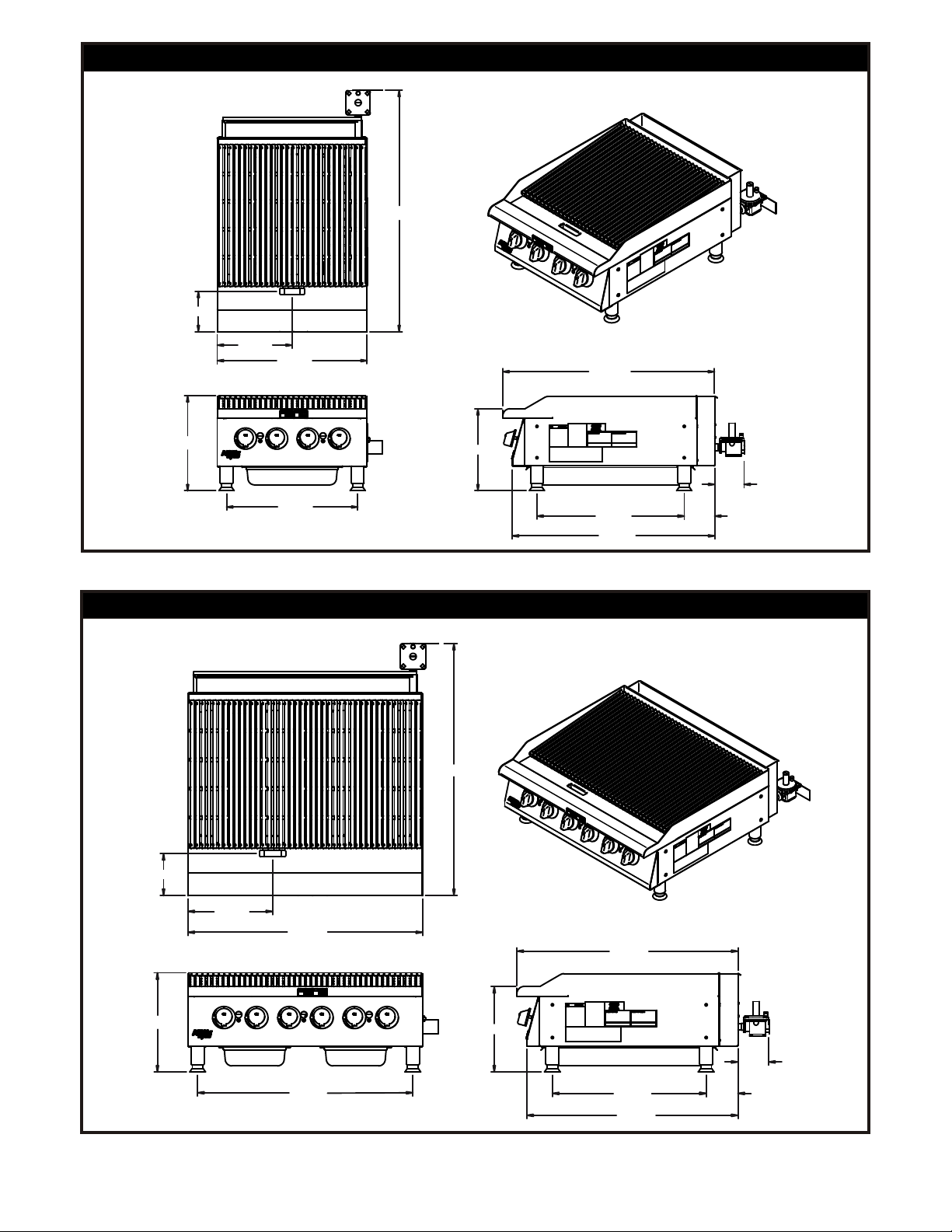
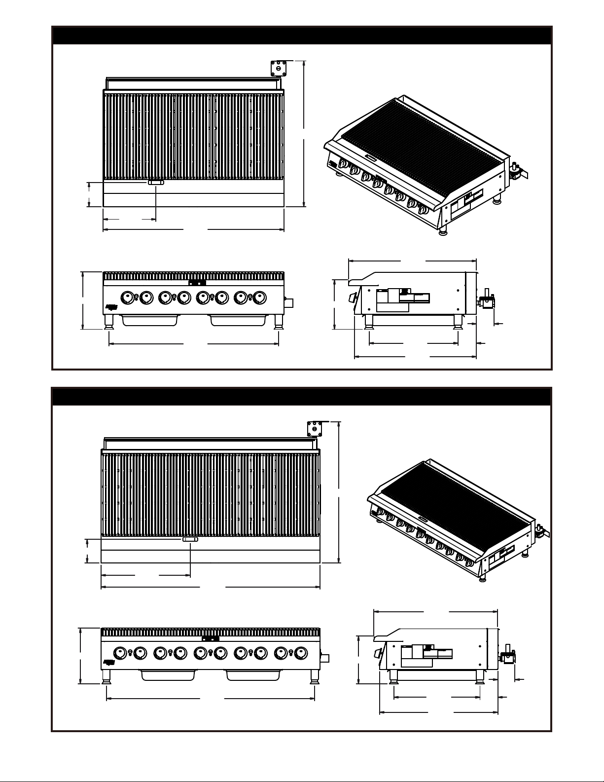
SPECIFICATIONS AND DIMENSIONS
MODEL
HCB-2424 24" (609.6) 34.339” (872.2) 15.217" (386.5) 4 20,000 (5.86) 80,000 (23.4) 5 (12.4)
HCB-2436 36" (914.4) 34.339” (872.2) 15.217" (386.5) 6 20,000 (5.86) 120,000 (35.2) 5 (12.4)
HCB-2448 48" (1219.2) 34.339” (872.2) 15.217" (386.5) 8 20,000 (5.86) 160,000 (46.9) 5 (12.4)
HCB-2460 60" (1524.0) 34.339” (872.2) 15.217" (386.5) 10 20,000 (5.86) 200,000 (58.6) 5 (12.4)
HCB-2472 72" (1828.8) 34.339” (872.2) 15.217" (386.5) 12 20,000 (5.86) 240,000 (70.3) 5 (12.4)
HCRB-2424 24" (609.6) 34.339” (872.2) 15.217" (386.5) 4 20,000 (5.86) 80,000 (23.4) 5 (12.4)
HCRB-2436 36" (914.4) 34.339” (872.2) 15.217" (386.5) 6 20,000 (5.86) 120,000 (35.2) 5 (12.4)
HCRB-2448 48" (1219.2) 34.339” (872.2) 15.217" (386.5) 8 20,000 (5.86) 160,000 (46.9) 5 (12.4)
HCRB-2460 60" (1524.0) 34.339” (872.2) 15.217" (386.5) 10 20,000 (5.86) 200,000 (58.6) 5 (12.4)
HCRB-2472 72" (1828.8) 34.339” (872.2) 15.217" (386.5) 12 20,000 (5.86) 240,000 (70.3) 5 (12.4)
WIDTH
IN. (MM)
DEPTH
IN. (MM)
HEIGHT
IN. (MM)
# OF
BURNERS
BTU/kW PER
BURNER
NATURAL GAS
TOTAL
BTU/kW HOUR
W.C.
IN. (’Mbar’)
4
21825000
6.446
HCB & HCRB-2424, 24" GAS CHAR BROILER
HCB/HCRB-2424
38.645
12.003
24.000
33.875
21825100
6.446
15.217
13.119
21.000
23.580
32.379
4.875
HCB & HCRB-2436, 36" GAS CHAR BROILER
HCB/HCRB-2436
38.645
4.708
15.217
13.003
36.000
33.000
13.119
5
33.875
23.580
32.379
4.708
4.875
21825200
HCB & HCRB-2448, 48" GAS CHAR BROILER
HCB/HCRB-2448
38.645
6.446
14.003
48.000
33.875
15.217
21825300
6.446
13.119
45.000
23.580
32.379
HCB & HCRB-2460, 60" GAS CHAR BROILER
HCB/HCRB-2460
38.645
24.428
60.000
4.708
4.875
15.217
57.000
33.875
13.119
4.708
23.580
32.379
4.875
6

21825400
6.446
HCB & HCRB-2472, 72" GAS CHAR BROILER
HCB/HCRB-2472
38.645
36.000
72.000
34.339
15.217
69.000
13.119
23.580
32.379
4.708
4.875
7
 Loading...