

35A Series to Harbor Freight and similar collectors
35A Series to “Older
”
Delta 50
-
760 Collectors
(Rim diameter
Included
with
each 35A Series Filter
In
cluded with ETG
-
55 (Edge Trim Gasket):
211 Camars Drive, Warwick, PA 18974
(215) 442-9443, fax (215) 442-9445
www.WynnEnv.com
Filter Kit Instructions
35A Series Assembly Instructions
:
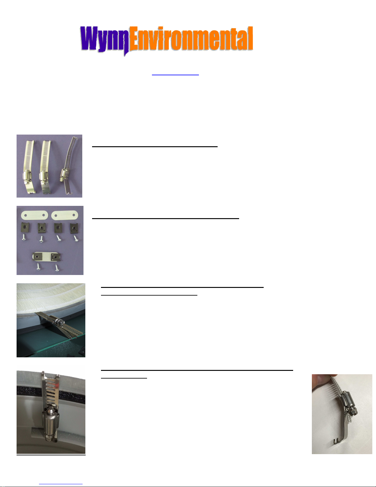
(1) Filter #35A100SBOL, #35A274BLOL or 35A274NANO
(3) FGL-U (Floating Gear Latches. (2) Poly Bag #1940PB
When installing or adjusting these latches please hold the body of the latch firmly
with pliers.
(3) Latch Keepers, (6) Spring Nuts (uni-directional)
(6) Screws
Only used on collectors with an upper rim diameter of less
than 17 inches.
(Rim diameter more than 18” :
• Underside of filter and hole in orifice pan shown in
photo.
• Filter Gasket seats against the surface of the orifice
pans, check the surface for flaws.
• Latches get placed in a triangular pattern on the
underside of the filter (shown at top of photo)
• Collector orifice pan rim show at bottom of photo
• Do not over tighten the latches
less than 18” :
• The filter rests on top of the collector rim so a gasket is
needed. Our ETG-55 edge trim gasket is recommended.
• There is no orifice pan but these collectors have an internal
ring to which the latches get anchored from underneath.
(see Photo left)
• Customer must bend a ½” offset at the bottom of each latch
(see photo right)
• Do not over tighten the latches
35A Series Instructions, Revision G, January 8, 2018
35A Series to a “Newer” Delta 50
-
760 and similar collectors
(Rim diameter
•
Do not over tighten the latches.
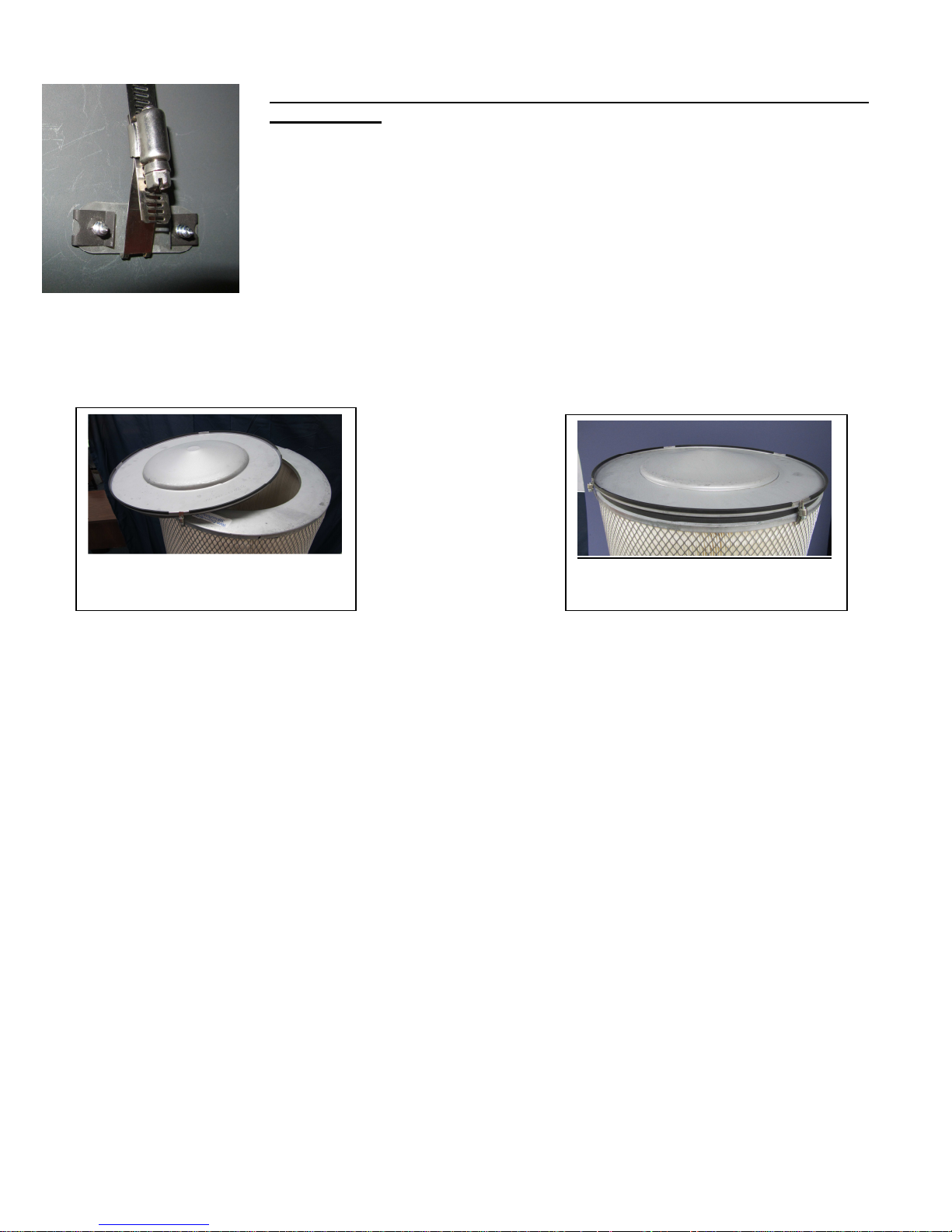
First:
less than 18”:
• The filter rests on top of the collector rim so a gasket is needed. Our ETG-
55 edge trim gasket is recommended. There is no orifice pan or inner ring to
anchor the latches to so the enclosed latch keepers are needed.
• About 2 – ½” from the top, spaced evenly, mark the location where the latch
keepers will go, then with a 3/16” drill bit, drill the mounting holes. Clip the
spring nuts over the holes of each keeper and with the provided screws;
secure the keepers on the inside. (see photo left)
35BA222NANO
Assembly Instructions
Shown Partially Assembled
Open end is shown
Shown With top end cap
secured
Before placing the provided (loose) top end cap onto the filter, install the filter onto your collector.
Installation varies with the configuration of the collector.
Next: (Important)
If you will be Incorporation a DIY “Filter Monitor” (Found under Woodworking Filters on our site), now is
a good time to do it while the end cap is loose.
Next:
Top End cap Preparation:
• Cut the provided thin rubber protective trim into four (4) 12” lengths.
• With about 1–1/2” inches between them, press each segment onto the rim leaving room for the
“provided” (small) floating gear latches.
• With the Trim facing upward and gasket facing downward, place the end cap onto the fixed (open)
filter end cap. Allign it.
• Pre-adjust each of the small provided Floating Gear Latches to about 1-1/4 inches (prong ID to
prong ID.
• Secure it with all the latches as shown. When installing or adjusting the latches, please hold the
body of the latch firmly with pliers. Do not over tighten.
35A Series Instructions, Revision G, January 8, 2018
 Loading...