

Page 1
Electrium Sales Limited, Walkmill Lane, Cannock, WS11 0XE
Tel: 01543 455000 Fax: 01543 455001
LF1726-1.docx Page 1 of 2
Installation Instructions
125A Integral Surge Protection Kit 10kA
NHTNSP125L
DANGER: LIVE PARTS ENCLOSED. Ensure the unit is installed by a qualified competent person in accordance with all
relevant legislation and regulations including building regulations and wiring regulations BS7671. If in doubt, contact a
qualified competent person.
IMPORTANT INFORMATION
Follow the instructions below before working on or inside the equipment.
• Turn off all power supplies
• Always use a calibrated volt-sensing device to confirm the power is off.
• Replace all devices, doors and covers before turning on the power to this equipment.
• To avoid ingress of swarf and similar material, always remove gland plates to allow cutting/slotting for cable entries.
• Do not use power screwdrivers on electrical connections.
Failure to follow these instructions could result in serious injury or death.
DO NOT USE POWER TOOL SCREWDRIVERS ON ELECTRICAL CONNECTIONS
• Remove the front shield from the DB (Distribution Board).
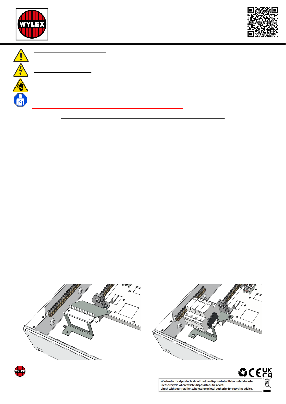
• Fit DIN bracket to bottom left hand side of DB as shown in fig. 1.0. Use screws provided.
• Fit surge assembly onto DIN bracket, see Fig 1.1.
• Remove bottom left hand side knockout from DB shield. Place shield back onto the DB so that the surge
arrestor protrudes through the newly created aperture. Adjust the position of the surge arrestor on the DIN
bracket until the shield aligns with the DB enclosure. Remove shield and fix surge arrestor at defined position
using DIN clips provided.
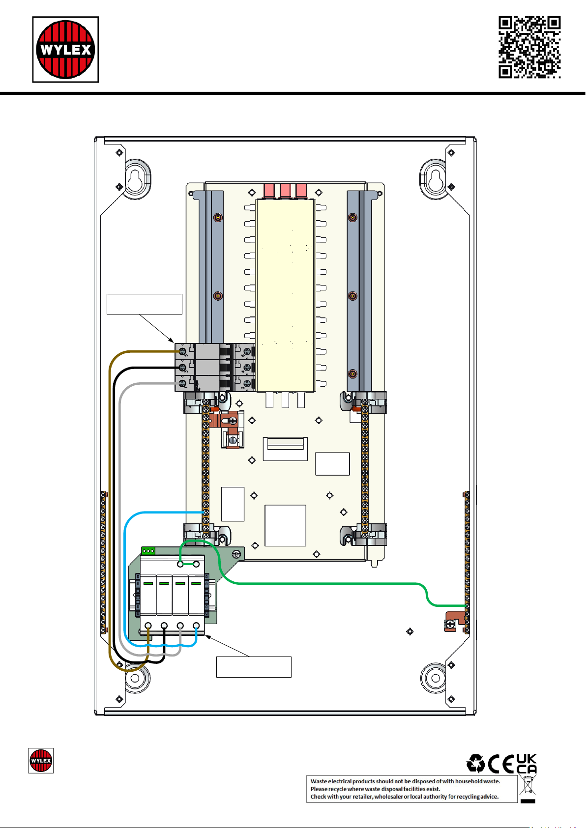
• Connect the supplied MCB to the lower left hand side busbar position as shown in Wiring Diagram - Fig. 2.
Torque as per DB instruction leaflet.
• Connect the brown marked cable between the L1 phase of MCB and L1 terminal of surge device, black
marked cable between L2 terminals and grey marked cable between L3 terminals as shown in Fig. 2.
• Connect the blue marked cable between the DB neutral bar and the surge arrestor neutral terminal as shown
in Fig. 2
• Connect the green and yellow earth cable between the DB earth bar and the surge arrestor earth terminal
(see Fig. 2). Preferable connection point is onto the terminal bar where the incoming earth cable is connected.
• Fully tighten all connections to the torque settings as recommended in the distribution board instruction leaflet
and surge device leaflet.
• NOTE - Disconnect the supply to the device or unplug the protective module before performing an insulation
measurement in the system. Otherwise, inaccurate measurements are possible. Reconnect the supply /reinsert the module into the base element after the insulation measurement.
• Before fitting the front shield, check the tightness of all connections, including factory made connections.
• Re-fit DB shield and place insulation testing label onto the shield (supplied with surge device), below the surge
device.
• Switch on MCB supply to surge device.
• NOTE – for further instructions on surge device, replacement of the plug-in module and more, please refer to
surge device leaflet.
Fig. 1.0
Fig. 1.1
Page 2
Electrium Sales Limited, Walkmill Lane, Cannock, WS11 0XE
Tel: 01543 455000 Fax: 01543 455001
LF1726-1.docx Page 2 of 2
Installation Instructions
125A Integral Surge Protection Kit 10kA
NHTNSP125L
L1
L2
L3
DB NEUTRAL BAR
DB EARTH BAR
SURGE DEVICE
MCB DEVICE
L1 L2 L3 N
PE
Wiring Diagram - Fig. 2.
 Loading...