

Page 1
WYLER AG
MANUAL
Im Hölderli
CH-8405 WINTERTHUR
Switzerland
Tel. 0041 (0) 52 233 66 66
Fax. 0041 (0) 52 233 20 53
Homepage: http://www.wylerag.com
E-Mail: [email protected]
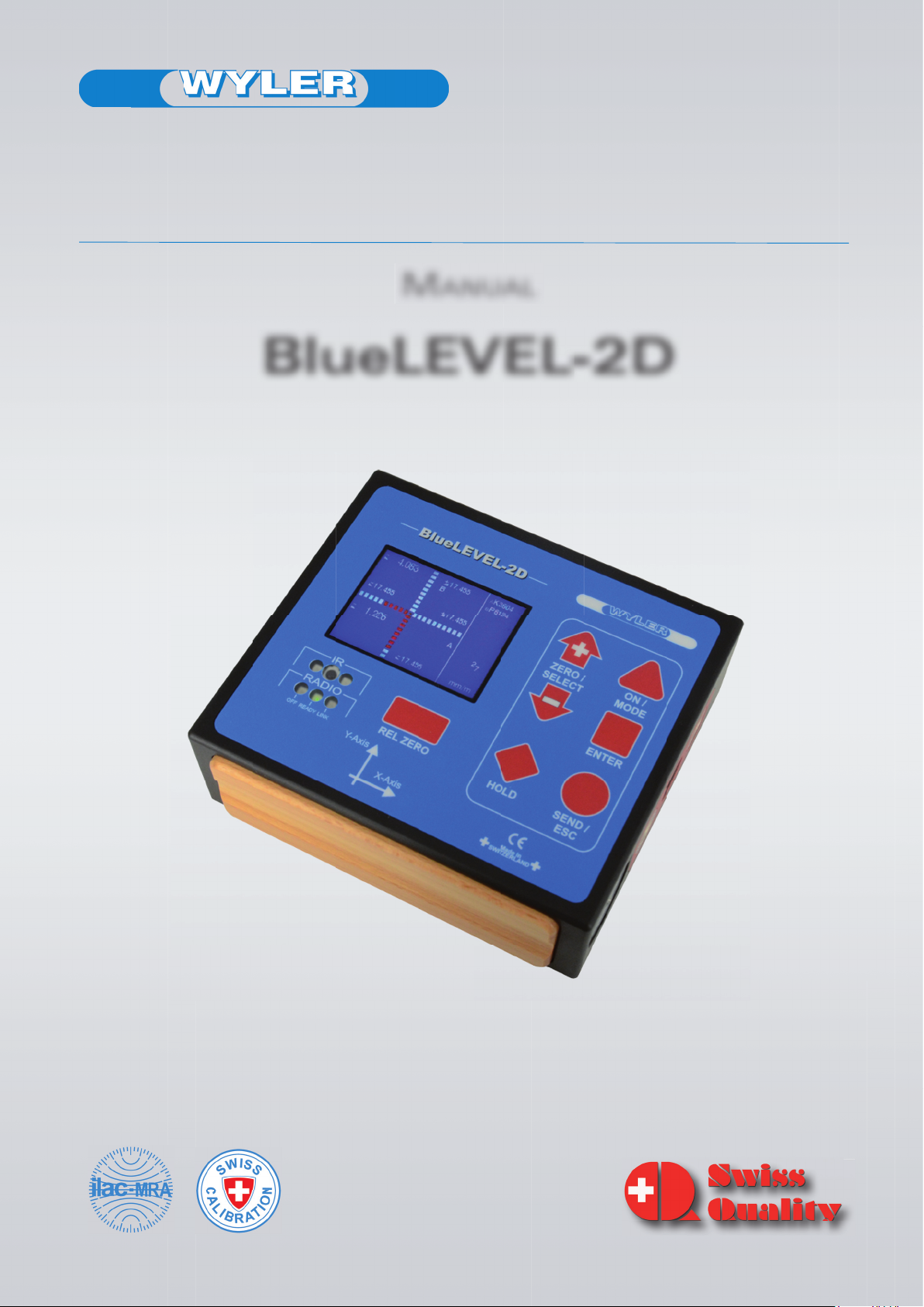
BlueLEVEL-2D
Page 2

Page 3

CONTENT
SUBJECT
PAGE
1. INTRODUCTION
7
1.1. DESCRIPTION OF THE BLUELEVEL-2D
7
1.2 PREPARATION AND START-UP
7
1.2.1 BATTERIES
7
1.2.2 POSSIBLE CONFIGURATIONS
8
2 STARTING
10
2.1 OPERATION/ SHORT DESCRIPTION
10
2.1.1 OVERVIEW KEYBOARD AND DISPLAY
10
2.1.2 HOW TO SWITCH THE INSTRUMENT ON AND OFF
11
2.1.3 KEYS / FUNCTIONS / SHORT DESCRIPTIONS OF EACH SINGLE KEY
11
2.2 DISPLAY
13
2.2.1 SCALING OF THE DISPLAY
13
2.2.2 DISPLAY TYPES
14
2.2.3 BACKGROUND COLOUR
15
2.2.4 BRIGHTNESS
16
2.3 SHORT DESCRIPTION OF THE INDIVIDUAL DISPLAY AREAS
17
3 OPERATING INSTRUCTIONS BLUELEVEL-2D
18
3.1 "ZERO-SETTING" / ABSOLUTE ZERO
18
3.1.1 SET ABSOLUTE ZERO (WITH A REVERSAL MEASUREMENT)
18
3.2 SELECTION OF THE MEASURING UNIT / UNIT
20
3.2.1 STANDARD-UNITS
20
3.2.2 UNITS WITH RELATIVE BASE LENGTH
20
3.3 FUNCTION HOLD
21
3.4 SELECTION OF THE FILTER UNDER DIFFERENT MEASURING CONDITIONS /
FILTER
22
3.5 ABSOLUTE MEASUREMENT / RELATIVE MEASUREMENT
22
3.5.1 ABSOLUTE MEASUREMENT
22
3.5.2 RELATIVE MEASUREMENT / REL ZERO
23
3.6 MEASURING WITH LIMITS / LIMITS
24
3.7 GROUPING OF INSTRUMENTS TO A MEASURING GROUP IN THE WIRELESS MODE
26
3.7.1 GROUPING VIA CABLE CONNECTION / JOIN
26
3.7.2 GROUPING IN THE WIRELESS MODE / JOIN
26
3.8 TEACH-IN of the IR-trigger (Zapper)
27
4 OPTIONS
28
4.1 SET PIN-CODE
29
4.2 DISPLAY SETTINGS
29
4.3 LOGSCALE
30
4.4 PROGRAMMABLE KEYS
31
4.5 FUNCTIONS ON/OFF
32
4.6 HIDE DISABLED FUNCTIONS ON/OFF
32
4.7 RADIO ON/OFF
33
4.8 GRAVITATION
33
4.9 VERSION FIRMWARE
34
4.10 RESET QUICK CALIBRATION (ONLY POSSIBLE WITH QUICK CALIBRATION
OPTION)
34
4.11 FACTORY RESET
35
4.12 FUNCTION CHECK
36
APPENDICES
37
A FLOAT CHARTS GENERAL
37
A1 START THE INSTRUMENT / ON/OFF
37
A2 KEY REL.ZERO
38
A3 KEY HOLD, FREEZING OF A MEASURING VALUE / HOLD
39
A4 MENU SELECTION
40
A5 ADJUSTMENT OF THE DISPLAY / DISPLAY
41
A6 MEASUREMENT ABSOLUTE / MODE ABSOLUTE
42
page 3 of 65 pages
Page 4

A7 MEASURING ABSOLUTE CONSIDERING THE ZERO OFFSET / MODE
ABSOLUTE ZERO
43
A8 MEASURING RELATIVE / MODE REL ZERO
44
A9 ADJUSTMENT OF THE MEASURING UNIT / UNIT
45
A10 SETTING OF LIMITS / LIMITS
46
A11 ADJUSTMENT OF FILTER TYPES / FILTER
47
A12 GROUPING OF INSTRUMENTS WITH WIRELESS TRANSMISSION / JOIN
48
A13 LEAVING A GROUP OF INSTRUMETNS / LEAVE
49
B FLOAT CHARTS OPTIONS
50
B1 PIN-CODE-QUERY FOR ACCESS TO THE OPTIONS
50
B2 SET PIN CODE
51
B3 DISPLAY SETTINGS
52
B4 LOGARITHMIC SCALE ON/OFF / LOGSCALE ON/OFF
53
B5 PROGRAMMABLE KEYS "REL ZERO" AND "ZERO/SELECT" /
PROGRAMMABLE KEYS
54
B6 SWITCHING FUNCTIONS ON OR OFF / FUNCTIONS ON/OFF
55
B7 SWITCHING THE HIDING OF DISABLED FUNCTIONS ON OR OFF /
HIDE DISABLED FUNCTIONS ON/OFF
56
B8 SWITCH THE WIRELESS TRANSMISSION ON OR OFF / RADIO ON/OFF
57
B9 SWITCH THE COMPENSATION OF GRAVITY ON OR OFF / GRAVITATION
COMPENSATION
58
B10 DISPLAY THE FIRMWARE-VERSION / VERSION FIRMWARE
59
B11 RESET TO FACTORY SETTINGS / FACTORY RESET
60
B12 FUNCTION CHECK / DEVICE CHECK
61
C Error Messages
62
D MAINTENANCE
62
D.1 GENERAL
62
D.2 STORAGE/ CARE AND HANDLING OF THE BATTERIES
62
D.3 SPARE PARTS / ACCESSORIES
62
E CONFORMITY DECLARATIONS AND APPROVALS
63
F SERVICE AND REPAIR
63
F1 REPAIR OF MEASURING INSTRUMENTS AND DISPLAY UNITS
63
F2 SERVICE - AND MAINTENANCE CONTRACTS
64
Datum /
Date
Geändert durch /
Modified by
Beschreibung der Änderung /
Description of the modification
1.3.2014
HEH
Initial release
12.3.2014
MG
Some corrections
8.1.2015
HEH
New: CONFORMITY DECLARATIONS AND APPROVALS
Modifications / Änderungen:
In the link list below, you will find more information on different important topics:
• Important Product Information (e.g. Important Conformity Declarations and Approvals)
http://ww w.wylerag.com/en/support/certificates/
• Imagefilms, Instructional videos and Tutorials
https://www .youtube.com/user/wylerag
• Manuals und Compendium
http://ww w.wylerag.com/en/support/documentation/manuals/
• Representatives WYLER AG/ Product Training
http://ww w.wylerag.com/en/contact/representatives/
page 4 of 65 pages
Page 5
INDEX
Key word
Chapter
Page
A
ABSOLUTE MEASUREMENT / RELATIVE MEASUREMENT
3.5
22
ADJUSTMENT OF FILTER TYPES / FILTER
A11
47
ADJUSTMENT OF THE DISPLAY / DISPLAY
A5
41
ADJUSTMENT OF THE MEASURING UNIT / UNIT
A9
45
APPENDICES
A
37
B
BACKGROUND COLOUR
2.2.3
15
BATTERIES
1.2.1
7
BRIGHTNESS
2.2.4
16 C
CONFORMITY DECLARATIONS AND APPROVALS
E
63
D
DESCRIPTION OF THE BLUELEVEL-2D
1.1
7
DIRECTIVE ON WASTE ELECTRICAL & ELECTRONIC EQUIPMENT (WEEE)
D4
63
DISPLAY
2.2
13
DISPLAY SETTINGS
4.2
29
DISPLAY SETTINGS
B2
51
DISPLAY THE FIRMWARE-VERSION / VERSION FIRMWARE
B9
58
DISPLAY TYPES
2.2.2
14
E
Error Messages
C
62
F
FACTORY RESET
4.11
35
FLOAT CHARTS GENERAL
A
37
FLOAT CHARTS OPTIONS
B
50
FUNCTION CHECK
4.12
36
FUNCTION CHECK / DEVICE CHECK
B11
60
FUNCTION CHECK / DEVICE CHECK
B12
61
FUNCTION HOLD
3.3
21
FUNCTIONS ON/OFF
4.5
32 G
GENERAL
D1
62
GRAVITATION
4.8
33
GROUPING IN THE WIRELESS MODE / JOIN
3.7.2
26
GROUPING OF INSTRUMENTS TO A MEASURING GROUP IN THE WIRELESS MODE
3.7
26
GROUPING OF INSTRUMENTS WITH WIRELESS TRANSMISSION / JOIN
A12
48
GROUPING VIA CABLE CONNECTION / JOIN
3.7.1
26
H
HIDE DISABLED FUNCTIONS ON/OFF
4.6
32
HOW TO SWITCH THE INSTRUMENT ON AND OFF
2.1.2
11
I
INTRODUCTION
1
7
K
KEY HOLD, FREEZING OF A MEASURING VALUE / HOLD
A3
39
KEY REL.ZERO
A2
38
KEYS / FUNCTIONS / SHORT DESCRIPTIONS OF EACH SINGLE KEY
2.1.3
11
L
LEAVING A GROUP OF INSTRUMETNS / LEAVE
A13
49
LOGARITHMIC SCALE ON/OFF / LOGSCALE ON/OFF
B3
52
LOGSCALE
4.3
30
M
MAINTENANCE
D
62
MEASUREMENT ABSOLUTE / MODE ABSOLUTE
A6
42
MEASURING ABSOLUTE CONSIDERING THE ZERO OFFSET / MODE ABSOLUTE
A7
43
page 5 of 65 pages
Page 6

page 6 of 65 pages
ZERO
MEASURING RELATIVE / MODE REL ZERO
A8
44
MEASURING WITH LIMITS / LIMITS
3.6
24
MENU SELECTION
A4
40 O
OPERATING INSTRUCTIONS BLUELEVEL-2D
3
18
OPERATION/ SHORT DESCRIPTION
2.1
10
OPTIONS
4
28
OVERVIEW KEYBOARD AND DISPLAY
2.1.1
10
P
PIN-CODE-QUERY FOR ACCESS TO THE OPTIONS
B1
50
POSSIBLE CONFIGURATIONS
1.2.2
8
PREPARATION AND START-UP
1.2
7
PROGRAMMABLE KEYS
4.4
31
PROGRAMMABLE KEYS "REL ZERO" AND "ZERO/SELECT" / PROGRAMMABLE
KEYS
B4
53
R
RADIO ON/OFF
4.7
33
RELATIVE MEASUREMENT / REL ZERO
3.5.2
23
RESET QUICK CALIBRATION (ONLY POSSIBLE WITH QUICK CALIBRATION OPTION)
4.10
34
RESET TO FACTORY SETTINGS / FACTORY RESET
B10
59
S
SCALING OF THE DISPLAY
2.2.1
13
SELECTION OF THE FILTER UNDER DIFFERENT MEASURING CONDITIONS / FILTER
3.4
22
SELECTION OF THE MEASURING UNIT / UNIT
3.2
20
SERVICE AND REPAIR
F
63
SET ABSOLUTE ZERO (WITH A REVERSAL MEASUREMENT)
3.1.1
18
SET PIN-CODE
4.1
29
SETTING OF LIMITS / LIMITS
A10
46
SHORT DESCRIPTION OF THE INDIVIDUAL DISPLAY AREAS
2.3
17
SPARE PARTS / ACCESSORIES
D3
62
STANDARD-UNITS
3.2.1
20
START THE INSTRUMENT / ON/OFF
A1
37
STARTING
2
10
STORAGE/ CARE AND HANDLING OF THE BATTERIES
D2
62
SWITCH THE COMPENSATION OF GRAVITY ON OR OFF / GRAVITATION COMPENSATION
B8
57
SWITCH THE WIRELESS TRANSMISSION ON OR OFF / RADIO ON/OFF
B7
56
SWITCHING FUNCTIONS ON OR OFF / FUNCTIONS ON/OFF
B5
54
SWITCHING THE HIDING OF DISABLED FUNCTIONS ON OR OFF / HIDE DISABLED
FUNCTIONS ON/OFF
B6
55
T
TEACH-IN of the IR-trigger (Zapper)
3.8
27
U
UNITS WITH RELATIVE BASE LENGTH
3.2.2
20 V
VERSION FIRMWARE
4.9
34
Z
ZERO-SETTING / ABSOLUTE ZERO
3.1
18
Page 7
1 INTRODUCTION
The following parameters (among others) can be
set and changed at the BlueLEVEL-2D:
Units
Display of measuring range
Type of display
Filter settings
2 pieces 1.5V, Size “C” ALKALINE
1.1 DESCRIPTION OF BLUELEVEL-2D
The BlueLEVEL-2D is a high precision and compact inclination measuring instrument for 2 axes. In
spite of its small outer dimensions the instrument contains 2 inclination sensors one in X- and one in Ydirection together with a full graphical and color 2D-display.
Thanks to its precision and its size the BlueLEVEL-2D is perfectly suited for the alignment of machines
and machine parts. It can be used as stand-alone unit but can also be used in combination with a
WYLER measuring software.
The Blue Level-2D is designed as a high-precision measuring instrument
It is possible to send the measured data via an RS232 port to a PC/laptop and therewith to the WYLER
software LEVELSOFT PRO, MT-SOFT and LabEXCEL software.
The BlueLEVEL-2D contains two sensors based on the analog measuring principle. The analog
measuring principle is optimized for the measurement of straightness, flatness, etc. with handheld
instruments because this measurement principle provides a stable value very quickly, which is very
important for precise measurements and an efficient measurement process. Furthermore it is very
insensitive to low-frequency interference, as can sometimes occur in machine tools.
1.2 PREPARATION AND START-UP
PRIOR TO STARTING
Please read this manual prior to working with the BlueLEVEL-2D. You will get an overview on all the
functions and possibilities of this instrument. At the same time you get familiar with the handling of the
instrument and wrong handling and specifically the unintentional erasing of the calibration data can
be avoided.
1.2.1 BATTERIES
The batteries are not inserted in the instrument during shipment. It is strongly recommended to remove
the batteries during transport.
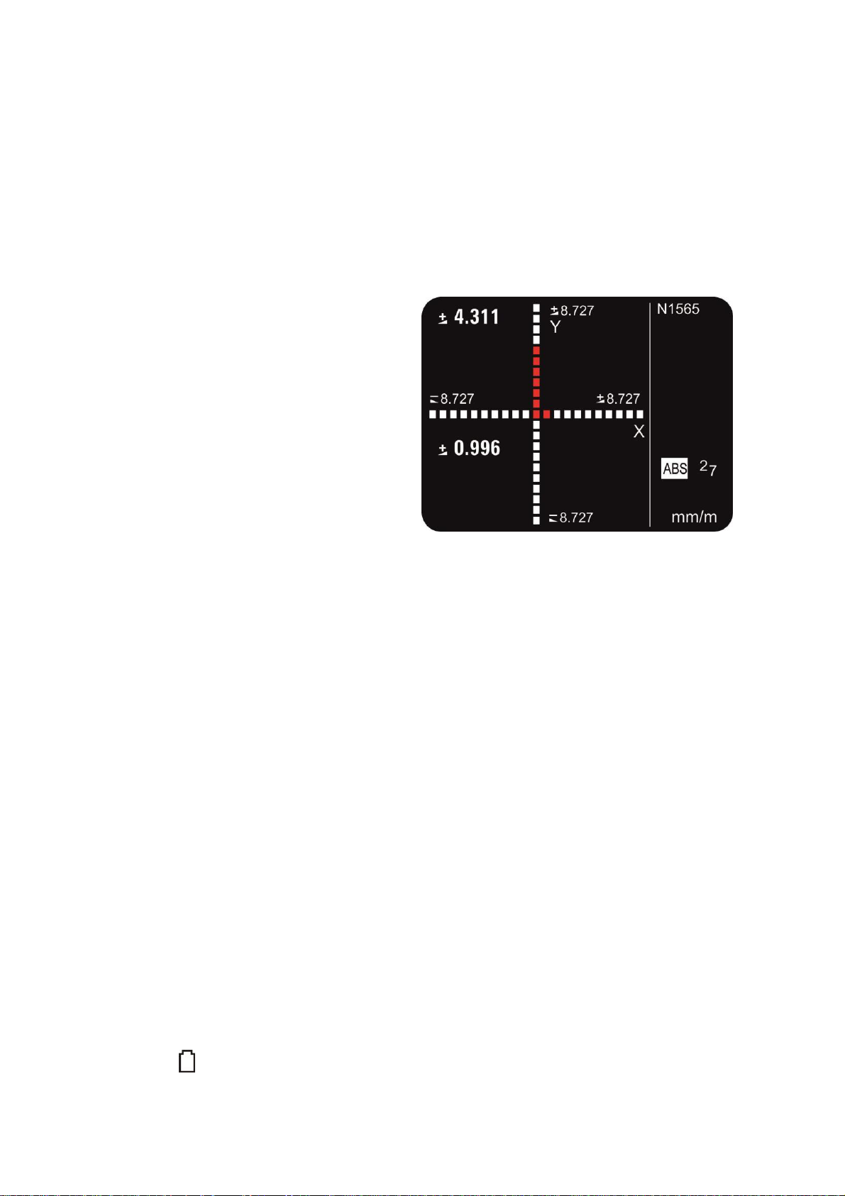
The battery voltage is shown in the display e.g. 27 (2.7 Volt)
Lowest possible battery voltage is 1.7 Volt. If the voltage drops below this value a blinking battery
symbol is shown: The batteries should then be exchanged rather soon.
page 7 of 65 pages
Page 8
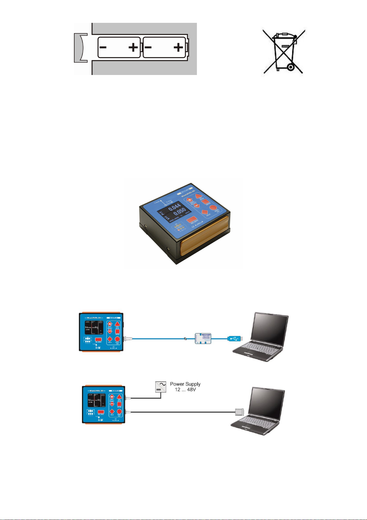
Stand-alone instrument
BlueLEVEL-2D connected via an USB cable to a PC/Laptop
A BlueLEVEL-2D connected to a laptop with the RS232 cable. The instrument is
powered from an external power supply
As an end user you are forced by law to return all used batteries and accumulators, a disposal through
household waste is prohibited.
Batteries/accumulators containing contaminants are marked with the symbol shown, which clearly
indicates the prohibition of disposal through household waste.
You can dispose of your used batteries/accumulators free of charge at the collecting points of your
community, our distribution partners or at each location selling batteries/accumulators. You thus fulfil
your legal obligation and contribute to the protection of the environment.
1.2.2 POSSIBLE CONFIGURATIONS
page 8 of 65 pages
Page 9
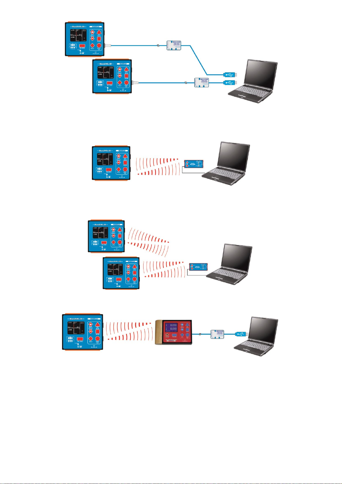
Two BlueLEVEL-2D connected to a laptop with USB cables allowing simultaneous differential
measurement in 2 directions. The instruments are powered from the USB-ports.
A BlueLEVEL-2D connected via Bluetooth to a BlueTC and to a laptop.
Two BlueLEVEL-2D connected via Bluetooth to a BlueTC and to a laptop.
Two BlueLEVEL-2D connected via Bluetooth to a BlueMETER SIGMA and to a laptop.
Please check the respective manuals and data sheets for detai ls on the other products shown above.
page 9 of 65 pages
Page 10
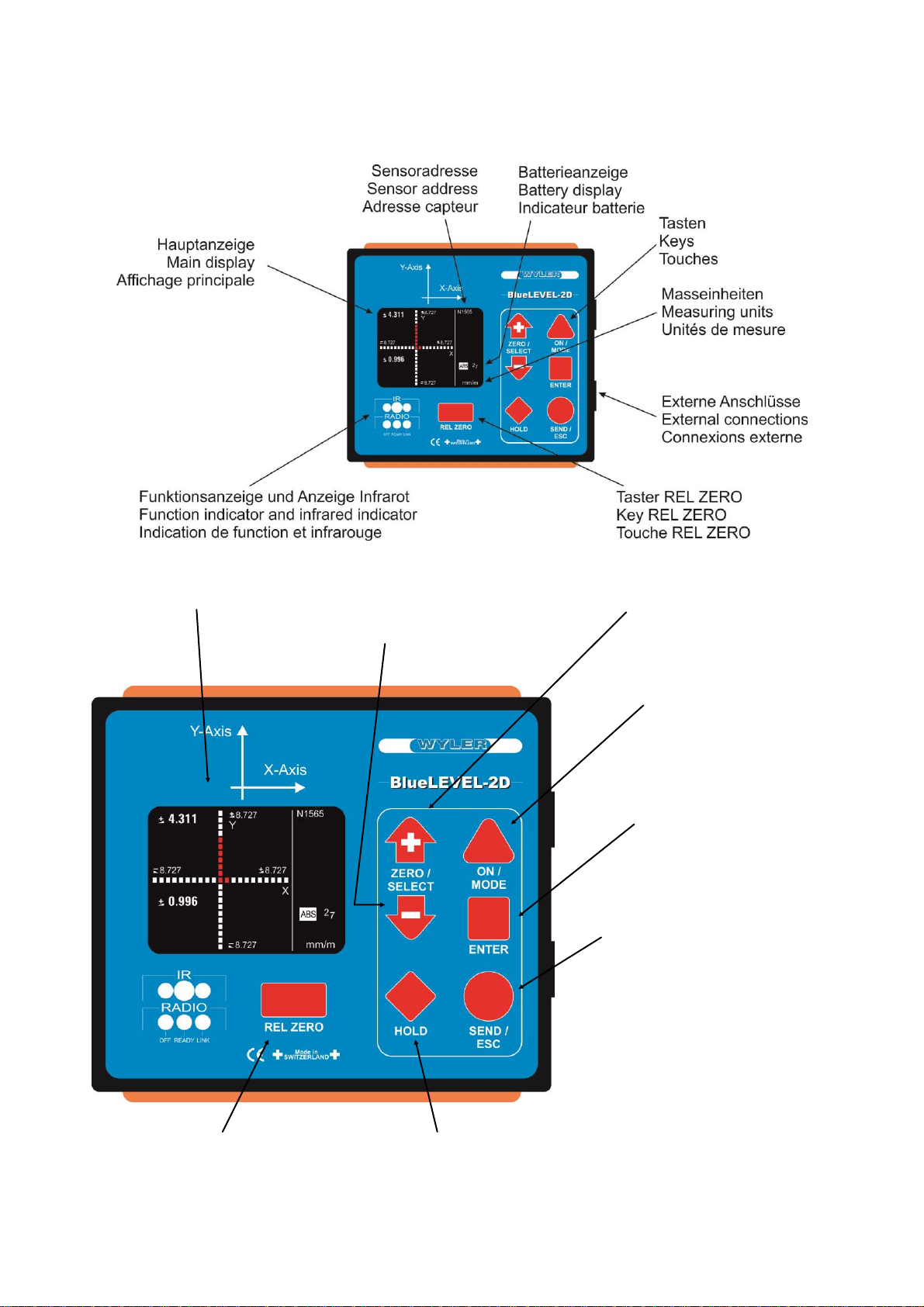
2 STARTING
Colour-display
<ZOOM OUT>
or
<previous option>
<ZOOM IN>
or
<next option>
<ON/OFF>
or
<select menu>
<accept selection>
or
<save entry>
<to print measuring value>
or
<unfreeze and print / transmit
HOLD - inclination value>
or
<escape from the menu>
To use current inclination as
<relative Zero>
<Freeze>
2.1 OPERATION/ SHORT DESCRIPTION
2.1.1 OVERVIEW KEYBOARD AND DISPLAY
page 10 of 65 pages
Page 11
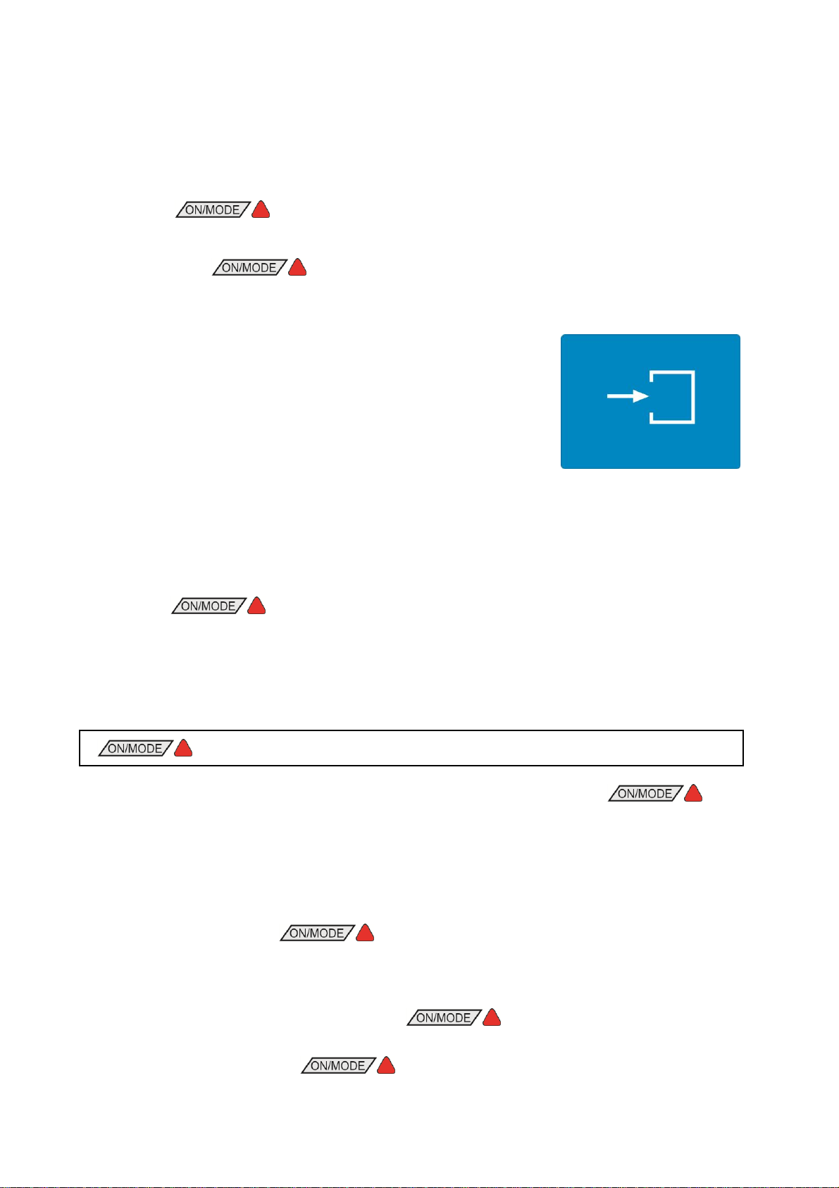
2.1.2 HOW TO SWITCH THE INSTRUMENT ON AND OFF
Keep the key pressed until the display and all LEDs
are lit and release the key. The instrument will automatically shut off
60 minutes after the last key operation.
If you keep the key pressed for more than 10
seconds the automatic OFF function is deactivated. This is
indicated by blinking LEDs.
The instrument carries out a short function test and establishes
connections to other instruments, if any had been available before
switching off the instrument.
The instrument changes into measuring mode. The settings, which
were used prior to switching the instrument off, are reloaded.
Keep the key pressed until the display disappears
(about 3 seconds). All settings are kept and will be reloaded again
next time the instrument is switched on.
ON/MODE - Key
Function - 1 -
To switch the BlueLEVEL-2D ON. When for starting the key is
pressed, a grey picture will appear on the screen and all LEDs will be
illuminated. After releasing the key the BlueLEVEL-2D is switching to the
measuring mode. The current inclination is displayed in the mode and unit
which was used before switching the instrument OFF. In case of an error the
respective error message is shown in the display. The instrument will
automatically shut of 60 minutes after the last key operation.
If the key is pressed for more than 10 seconds the LEDs start
blinking and the automatic OFF function is deactivated.
Exception: If the BlueLEVEL-2D is powered from an external power supply, the
automatic OFF function is deactivated and the instrument will remain ON.
Function - 2 -
To switch OFF, press the key more than 3 seconds, until the
display disappears.
Function - 3 -
With the key you open the menu. Pressing the key repeatedly
will move you through the menu which is indicated by the cursor moving down
to the required function.
The BlueLEVEL-2D features an automatic shut off. In normal mode the instrument is automatically
switched off 60 minutes after the last key operation. This automatic shut OFF function can be
deactivated with a special ON sequence or when using an external power supply
To switch ON
To switch OFF
2.1.3 KEYS / FUNCTIONS / SHORT DESCRIPTIONS OF EACH SINGLE KEY
page 11 of 65 pages
Page 12
ON/MODE - Key
Function - 4 -
While setting a value with the key the default value can be
recalled.
ENTER – key
Function - 1 -
The key is used to confirm a chosen function or to save a value
entered
Function - 2 -
While in the function "REL ZERO" or "ABS ZERO" the measuring can be
started or an ongoing measuring can be finished by pressing the key
SEND/ESC- key
Function - 1 -
The key is used to send / transmit a measuring value to a PC or
to a printer or similar output device through the RS485 port
Data format OUT port:
[sss xxxxxtt sn.nnnnnn xxxxxtt sn.nnnnnn <cr>]
sss = 0 .. 255 – sequence number
xxxxxtt = Sensor Serial Number and Type
e.g. N2473Dx BlueLEVEL-2D X-Axis
N2473Dy BlueLEVEL-2D Y-Axis
sn.nnnnnn = inclination in rad, e.g. +0.226349
+9.999999 -> Positive Overrange
-9.999999 -> Negative Overrange
Example: 112 N2473Dx -0.021033 N2473Dy +0.002289
Format of transmission:
asynchron, 7Bit, 2 Stopbits, no parity, 9600 Baud
Function - 2 -
Unfreeze of the "HOLD"- function to return to the measuring mode.
At the same time the “frozen” value is sent to the RS 485 port to any connected
device
Function - 3 -
Escape function from the menu
page 12 of 65 pages
Page 13
ZERO/SELECT "+/-" - key
Function - 1 -
The key is used to
changing the scale in the display
increase / decrease the display range
This function can, however, be disabled in the instrument settings.
Function - 2 -
The key is used to select possible adjustments, such as
menu selection
modification of a number
HOLD - key
Function - 1 -
The key serves for "freezing" a measuring value. The value is
displayed until the BlueLEVEL-2D returns to the measuring mode by pressing
the key.
Function - 2 -
In the functions "REL.ZERO" and "ABS.ZERO" the key is used
for reading in the actual measuring value again during the manual entering.
REL ZERO - key
Function - 1 -
The key serves for setting the actual inclination as the
relative Zero.
Using the key select the menu point [Options] and
confirm with . Select now [Logscale] and confirm with
2.2 DISPLAY
The BlueLEVEL-2D features various graphic displays which can be scaled according to the
requirements of the measuring task. Also the background colour and the brightness of the display can
be adjusted.
2.2.1 SCALING OF THE DISPLAY
For an optimal use of the graphic display, you have various options for scaling.
With the linear scaling the display precision remains constant over the full range. With the keys
the resolution can be changed. Thus also the range being displayed will be
changed.
With the logarithmic scaling the display precision around Zero is the highest and it is reduced
continuously with higher inclination values. Around Zero the resolution corresponds to the unit
selected.
In the adjustments of the instrument you can switch between linear and logarithmic scaling.
page 13 of 65 pages
Page 14
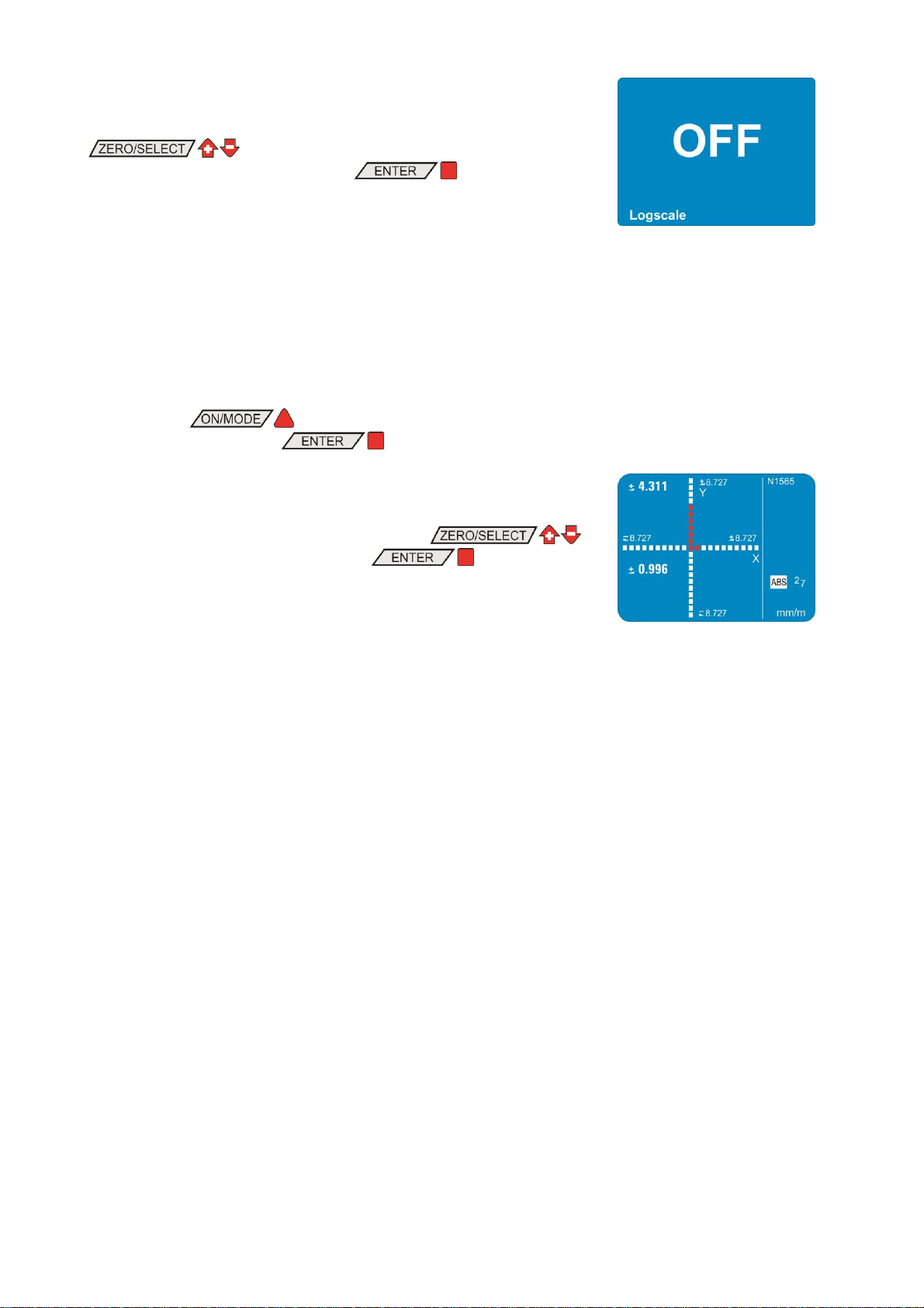
Switch the logarithmic scaling ON or OFF using the keys
. The display will show the requested state of
the instrument. Confirm with the key .
The instrument will return to the measuring mode. If the logarithmic
scaling is enabled, the symbol "LOG" will appear below the graph.
Using the key select the menu point [Display] and
confirm this selection with .
Select the required display type using the keys
and confirm your selection with the key .
The instrument will return to the measuring mode.
2.2.2 DISPLAY TYPES
The display type can be selected in the menu "display".
page 14 of 65 pages
Page 15
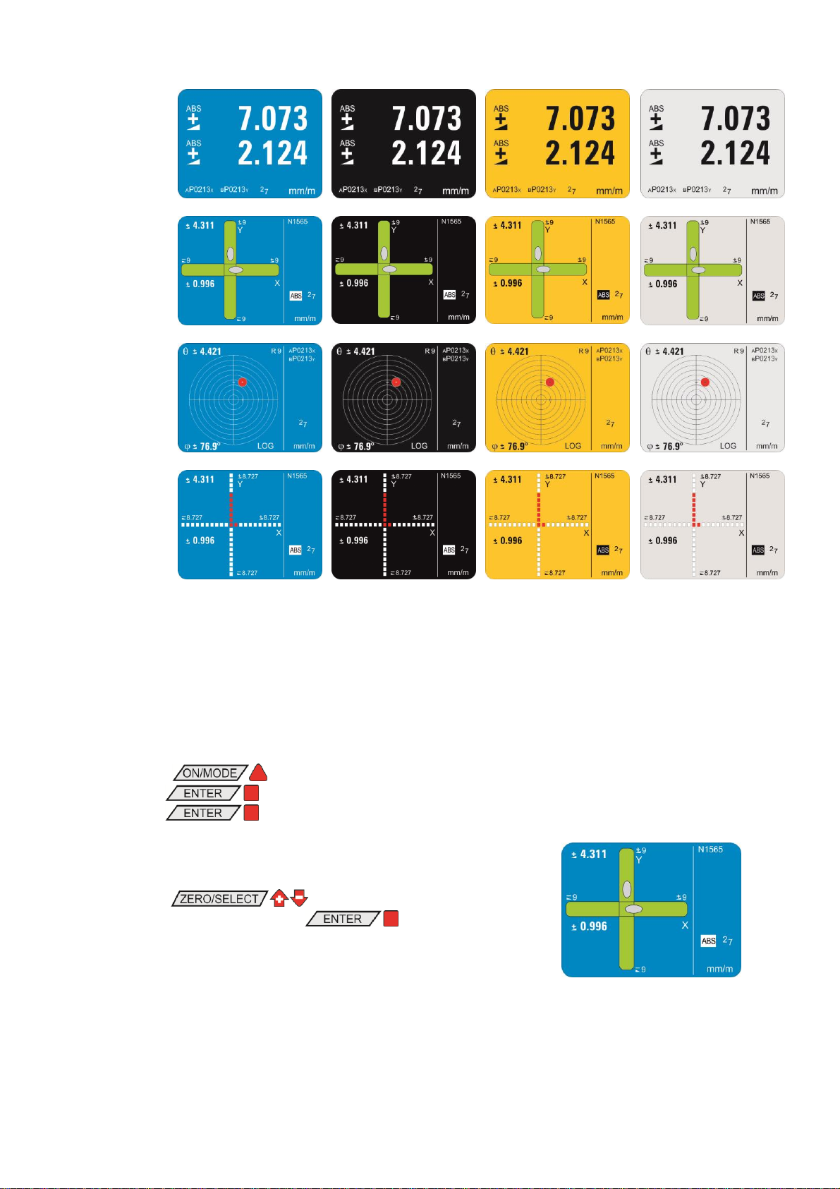
The following display types are available in the BlueLEVEL-2D:
Numeric
display
Display
with cross
vial
Display
target
Display
LED-cross
Using the key select the menu point [Options] and
confirm with . Select now [Display Settings] and
confirm with
With the keys select the display colour and
confirm the selection with the key .
The instrument will return to the measuring mode.
2.2.3 BACKGROUND COLOUR
In the adjustments of the instrument the background colour can be selected. Depending on the
brightness of the colour selected the colour of the fonts and the symbols will change between black
and white.
page 15 of 65 pages
Page 16
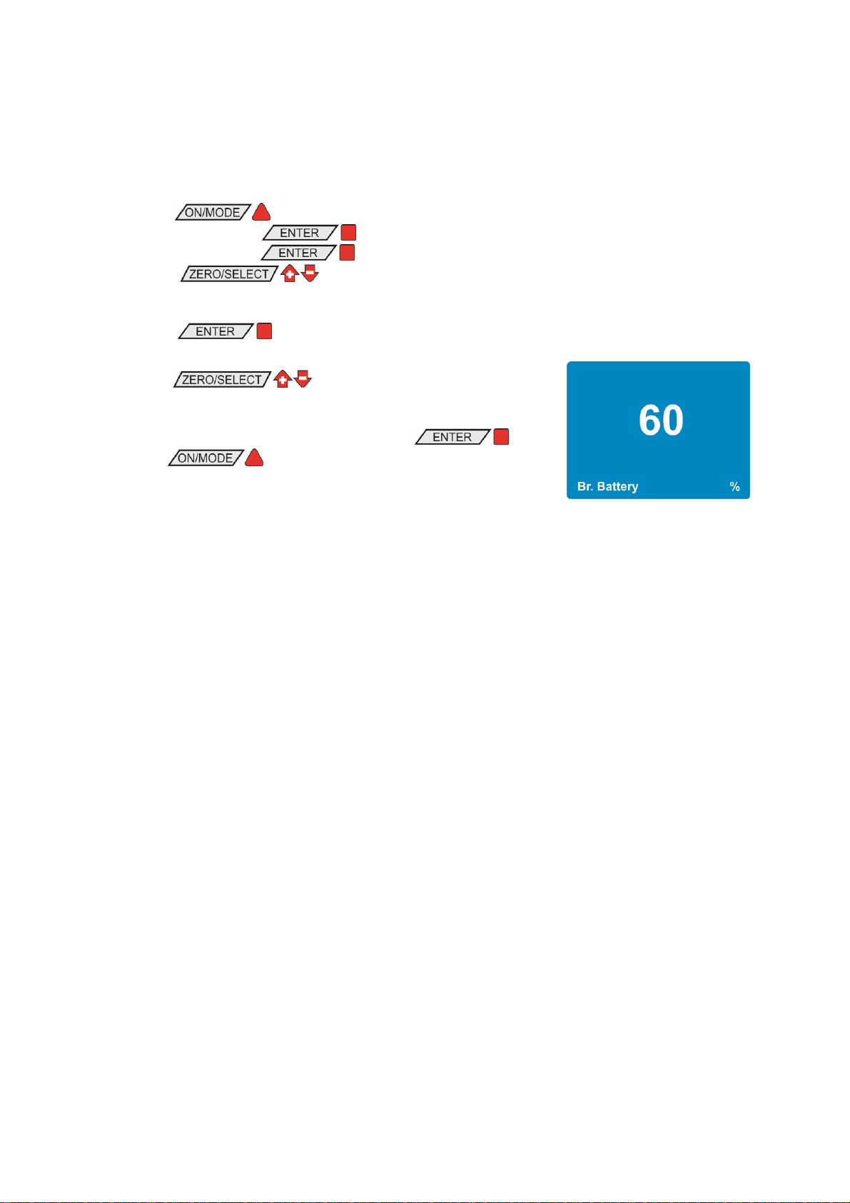
2.2.4 BRIGHTNESS
Using the key on mode select the menu point
[Options] and confirm with . Select now [Display
Settings] and confirm with .
Using the keys select [Brightness] for the
adjustment when using an external power supply and [Brightness
Powersave] for the adjustment in battery operation. Confirm this
selection with .
With the keys you can adjust the brightness
required. The display will show the power consumption in a range
from 10% to 100% of the maximum brightness. Only steps of 10%
are possible. Confirm the adjustment with the key .
With the key the default value of 50% will be
recalled.
The instrument will return to the measuring mode.
Adjustment of the brightness of the display. Difference between battery operation and the use of an
external power supply.
In the adjustments of the instrument the brightness of the display can be adjusted in order to adapt it to
the environmental conditions and to optimise the battery life time. Thus two different values can be set
for the battery operation and the operation with an external power supply
page 16 of 65 pages
Page 17
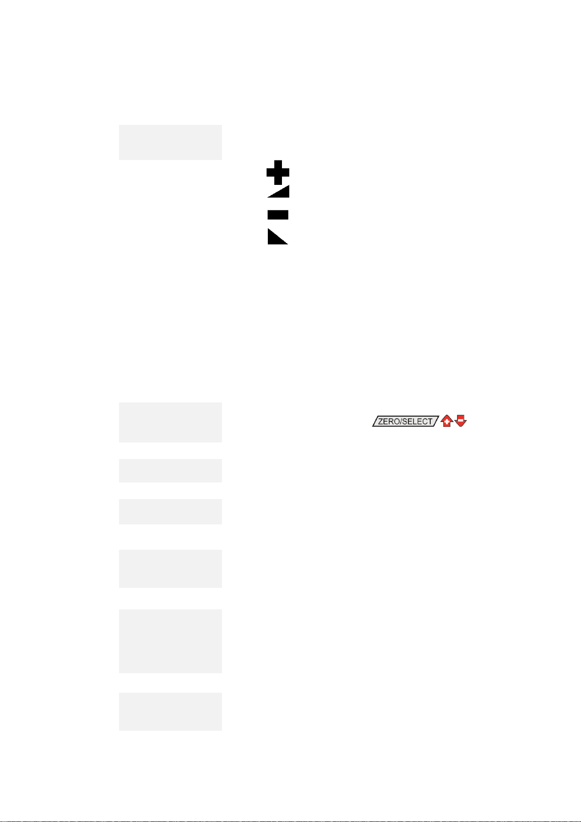
2.3 SHORT DESCRIPTION OF THE INDIVIDUAL DISPLAY AREAS
Main
display
In the main display the actual measuring value will be displayed.
Display of the
direction of the
inclination
A symbol indicates the direction of the inclination of the value
displayed.
inclined to the right
(positive inclination)
declined to the right
(negative inclination)
on hold
The HOLD function is activated, i.e. the measuring value is
"freezed".
ABS
Absolute measurement is activated.
REL
Relative measurement is activated, i.e. the measuring value is
the difference between the current and the reference plane,
i.e. the relative base.
displaying range
60°
Shows the selected displaying range. The displaying range
can be adjusted using the keys provided
that this function is enabled in the options.
scale division
5°
Angle between two tick marks.
Scale division
LOG
Indicates that the logarithmic scale is in use. If this sign is
missing, the linear scale is in use.
Serial number
Shows the serial number of the instrument.
X-Axis: A+Serial number+X
Y-Axis: B+Serial number+Y
Battery voltage
26
Display of the current battery voltage (example 2.6 V). The
lowest possible voltage is 1.7 Volt. After a further voltage drop
a blinking battery symbol will appear. The batteries must then
be exchanged immediately. A plug symbol will appear when
the instrument is powered by an external source.
Measuring unit
Display of the measuring unit in use. There are 10 basic units
available, whereas for each setting various options can be
selected.
page 17 of 65 pages
Page 18
3 OPERATING INSTRUCTIONS BLUELEVEL-2D
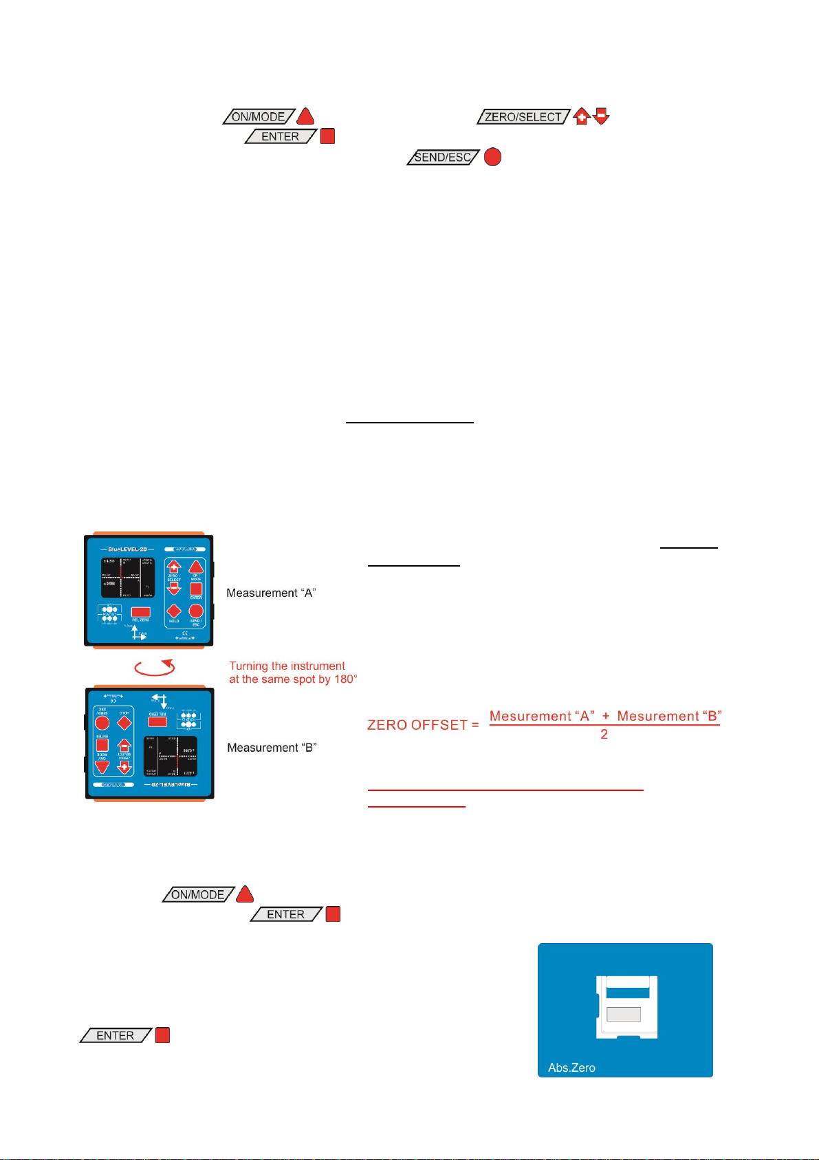
The absolute zero will be determined from a reversal
measurement (two measurements in opposite
direction but at the same spot). Use for this procedure
an adequate surface (rigid and stable support, as flat
as possible and as horizontal as possible), where you
put the BlueLEVEL-2D. Mark the position and the
direction of the BlueLEVEL-2D precisely and turn it on
the same spot by 180 degrees.
The "ZERO-OFFSET" will be stored in the
BlueLEVEL-2D
With the key select the menu item [Abs ZERO] and
confirm this selection with .
In the display the position of the instrument for the first
measurement will be shown.
Put the BlueLEVEL-2D to the first position and press the key
for reading the first measuring value. Alternatively
the first measuring value can also be entered with the zapper.
The BlueLEVEL-2D offers a wide range of functions and adjustment possibilities. The list of functions
appears when the key is pressed. With the keys the desired function
can be selected and with it will be started. If during 10 seconds no further key is
operated, the function list will be left. With the key a function selected can be
abandoned. Already entered changes of param eters wi l l be rejected and the BlueLEVEL-2D will return
to the previously used display mode.
Here after the single functions will be described.
3.1 "ZERO-SETTING" / ABSOLUTE ZERO
Absolute ZERO means that the instrument shows the measuring value "0" if the measuring surface of
the instrument is aligned exactly according to gravity (true horizontal or true vertical).
3.1.1 SET ABSOLUTE ZERO (WITH A REVERSAL MEASUREMENT)
The absolute zero is used as the base for absolute inclination measurements. In order to achieve the
best possible precision please observe that the measuring object (support) and the BlueLEVEL -2D
have the same temperature and that the instrument is in operation for several minutes before starting a
measurement. The surface needs to have a very good flatness.
Mark the precise position and particularly the direction of the BlueLEVEL-2D in order to be able to turn
the instrument by 180 degrees and to put it in opposite direction at the very same spot.
EXAMPLE:
page 18 of 65 pages
Page 19
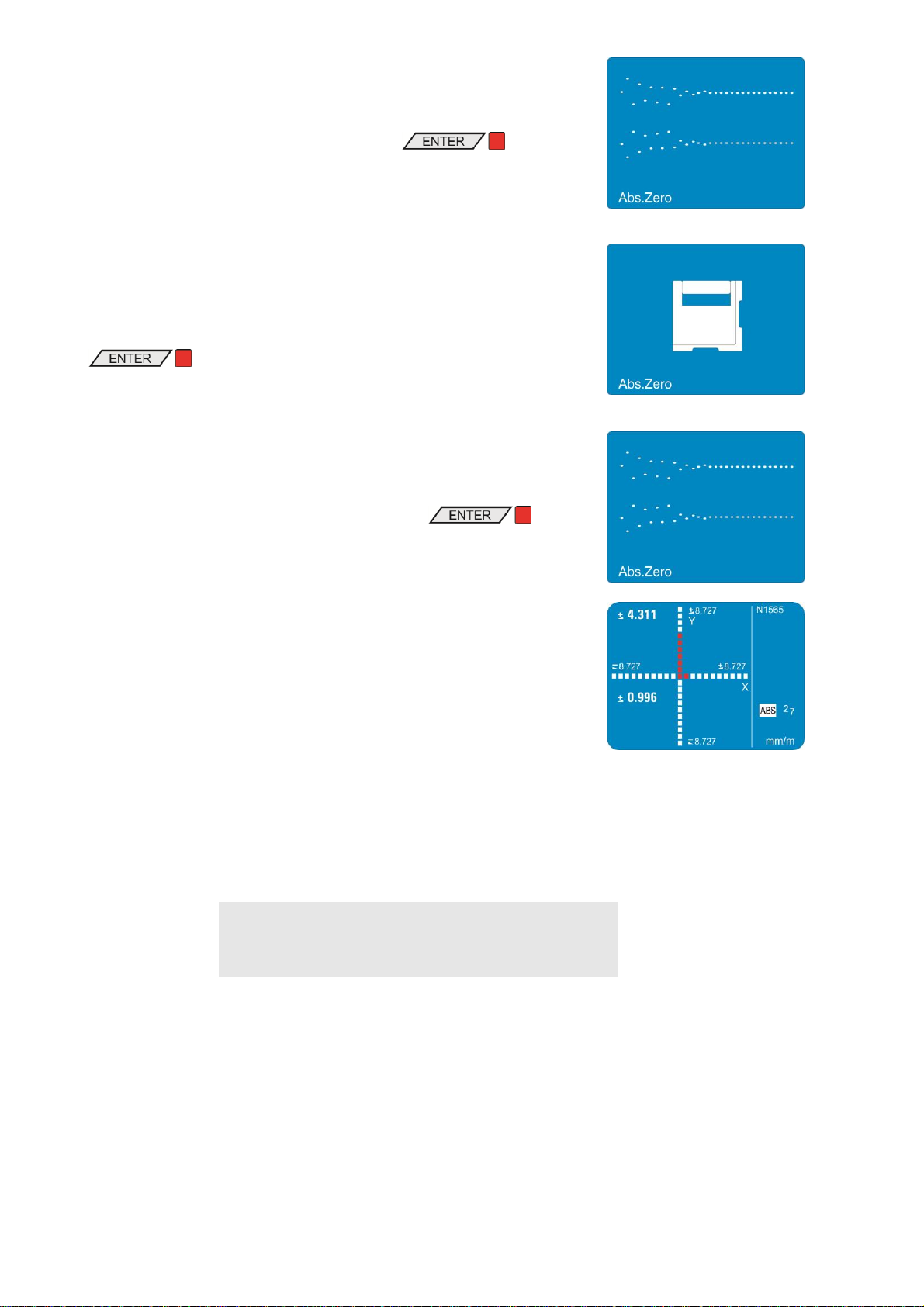
During the measurement the display will graphically show the
current measurement.
Confirm the first measurement with the key or with
the zapper. After 15 seconds the value will automatically be read.
After a successful reading of the first measuring value the position
of the instrument for the second measurement will appear in the
display.
Put the BlueLEVEL-2D now to the second position (turn the
instrument by 180 degrees in the horizontal) and press the key
again for reading the second measuring value.
Alternatively the second measuring value can also be entered with
the zapper.
During the measurement the display will graphically show the
current measurement.
Confirm the second measurement with the key or
with the zapper. After 15 seconds the value will automatically be
read.
After termination of the reversal measurement the display for the
actual measurement under consideration of the ZERO OFFSET
will appear on the screen.
Notice:
The value of the "ZERO OFFSET" determined by a reversal measurement corresponds to the deviation
of the zero point of the BlueLEVEL-2D compared to the absolute Zero (gravity). The displayed
measuring value corresponds to
VALUE displayed =
Value of the BlueLEVEL-2D minus "ZERO OFFSET"
The reversal measurement described above should be repeated periodically in order to achieve a high
measuring precision, particularly when the BlueLEVEL-2D has not been in use for a longer period.
page 19 of 65 pages
Page 20
3.2 SELECTION OF THE MEASURING UNIT / UNIT
xxxx.xx
mm/m
mm per m / 2 decimals
xxx.xxx
mm/m
mm per m / 3 decimals *
xx.xxxx
"/10"
inch per 10 inches / 4 decimals
xx.xxxx
"/12"
inch per 12 inches / 4 decimals
xxxx.xx
mRad
Milliradian / 2 decimals
xxx.xxx
mRad
Milliradian / 3 decimals
xxxx.xx
mm/REL
mm in relation to the relative base / 2 decimals
xxx.xxx
mm/REL
mm in relation to the relative base / 3 decimals *
xx.xxxx
"/REL
inches in relation to the relative base / 4 decimals
xxxx.xx
A %o
artillerie-permille
xxxx.xx
%o
permille
xxx.xxx°
DEG
degrees / 3 decimals
xxx° xx'
DEG
degrees / minutes
xx° xx' xx"
DEG
degrees / minutes / seconds
xxxx' xx"
DEG
minutes / seconds
xxxxxx"
DEG
seconds
xxxxx.x"
DEG
seconds *
xxx.xxx
GON
gon / 3 decimals
xx.xxxx
GON
gon / 4 decimals
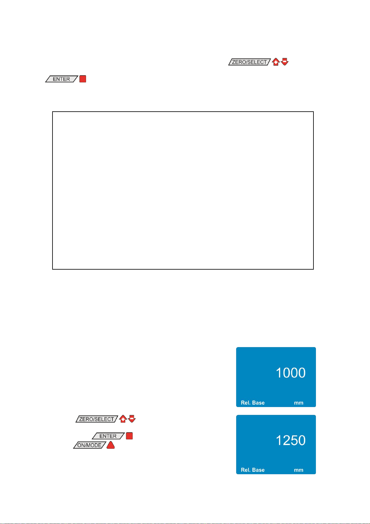
After the selection of the measuring unit in our example the
stored base length of 1000 mm will appear.
With the keys the proposed base length
can be modified. The newly entered value can finally be
confirmed with the key.
With the key the default value 1000 mm will be
recalled.
The following measurements are now related to a base length
of 1250 mm.
3.2.1 STANDARD-UNITS
You can change the measuring unit of the inclination values displayed. If you start the function [UNIT]
the list of the available measuring units will appear. With the keys you can now
select the measuring unit preferred. For memorizing the measuring unit selected you press now the
key . The measuring unit will remain active until you change it again according to the
above procedure.
The following measuring units can be chosen.
Depending on the unit selected the last digit will be rounded to 5" or to the nearest lower integer
(e.g.20 µmm/m).
3.2.2 UNITS WITH RELATIVE BASE LENGTH
The units mm/REL and "/REL are related to a relative, this means selectable, base length. After
selecting one of these units, the relative base length must be entered.
Example: mm/REL / mm in relation to a relative base / 2 decimals.
page 20 of 65 pages
Page 21
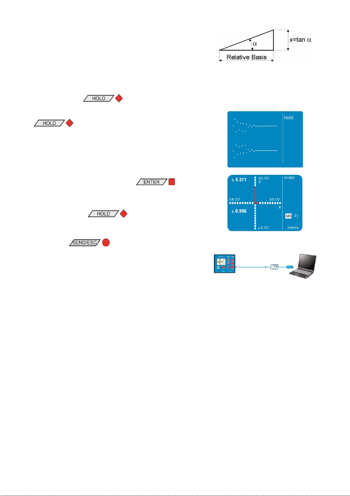
When measuring in the "relative mode" the height "X" will be
displayed as linear measure in the selected unit and in
relation to the set base length (in mm or inches).
Put the BlueLEVEL-2D on a stable support. Press now the key
. While the BlueLEVEL-2D is waiting for a valid
measuring value the display will show graphically the
measuring values read in the form of a shoal of points. As it is
practically impossible to obtain a valid measuring value
during manipulation, the instrument can be set to the final
position even after activating the key.
Complete the measurement with the key or with
the zapper. After 15 seconds the measuring value will
automatically be read.
By pressing the key again a new valid
measuring value will be read.
With the key the "frozen" measuring value will
be transmitted via the "RS485" port to a connected PC/Laptop
with an RS232 interface. At the same time the instrument will
return to the measuring mode.
The function SEND can also be initiated from the PC/Laptop
connected by sending "P" (as a letter) via the RS 232 port.
3.3 FUNCTION HOLD
The key function can be applied in all measuring modes.
page 21 of 65 pages
Page 22
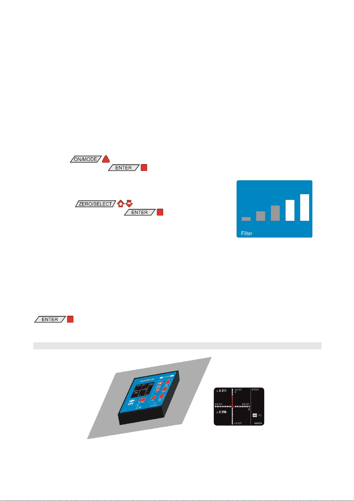
3.4 SELECTION OF THE FILTER UNDER DIFFERENT MEASURING CONDITIONS / FILTER
With the key select the menu item [FILTER] and
confirm this selection with .
Using the keys you can now select the filter type
desired and then confirm it with .
The measuring instrument will return to the measuring mode.
Inclination X: 0.996mm/m
Inclination Y: 4.311mm/m
A number of different predefined filters can be selected.
Description of the different filter types:
• FILTER 1: No filtering, no integration of the measuring values (T const. = 0.33 sec.)
• FILTER 2: Floating average of 3 measuring values (T const. = 1 sec.)
• FILTER 3: Floating average of 15 measuring values (T variabl e = 0.33 … 5 sec.)
• FILTER 4: Floating average of 6 measuring values (T const. = 2 sec.)
• FILTER 5: Floating average of 15 measuring values (T const. = 5 sec.)
T: Response time when changing the position. For filter 3 the actual change of the measuring value
will define the number of values to be used for calculating the floating average. With a considerable
change the number of values will be reduced with minute fluctuations the number will be increased.
Filter type 3 is the factory setting when leaving WYLER AG.
3.5 ABSOLUTE MEASUREMENT / RELATIVE MEASUREMENT
3.5.1 ABSOLUTE MEASUREMENT
As a factory setting the BlueLEVEL-2D will be programmed for absolute measurement (default setting).
If this is not the case select the function [Absolute]. After confirming this function with the key
the instrument is ready for measurements in the mode "ABSOLUTE".
The measuring value corresponds to the
value of the BlueLEVEL-2D minus "ZERO - OFFSET"
page 22 of 65 pages
Page 23
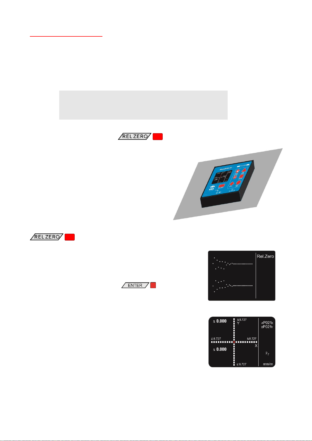
3.5.2 RELATIVE MEASUREMENT / REL ZERO
Put the measuring instrument on the reference surface.
The display shows the values X +0.996mm/m and
Y +2.311mm/m. This corresponds to the absolute
inclination of the reference surface.
Inclination X: 0.996mm/m
Inclination Y: 2.311mm/m
Set the BlueLEVEL-2D to the correct position and press the key
.
After 15 seconds the value will automatically be read.
During the measurement the display will graphically show the current
measurement.
Complete the measurement with the key or with the
zapper. After 15 seconds the measuring value will automatically be
read.
On the screen now the display for the actual measurement will
appear under consideration of the ZERO OFFSET.
Inclination X: 0.000mm/m
Inclination Y: 0.000mm/m
Important preliminary remark:
The "REL ZERO OFFSET" determined for a relative measurement will be superposed to the "ZERO
OFFSET", e.g. determined by a reversal measurement.
The "REL ZERO OFFSET" will be stored in the BlueLEVEL-2D and can be re-called again and again.
When starting the next relative measurement the "REL ZERO OFFSET" entered or determined the last
time will be displayed. The value can either be confirmed, newly entered or set to zero.
Value displayed =
Value of the BlueLEVEL-2D - "ZERO-OFFSET" - "REL ZERO
Abbreviated procedure with the key :
OFFSET"
page 23 of 65 pages
Page 24
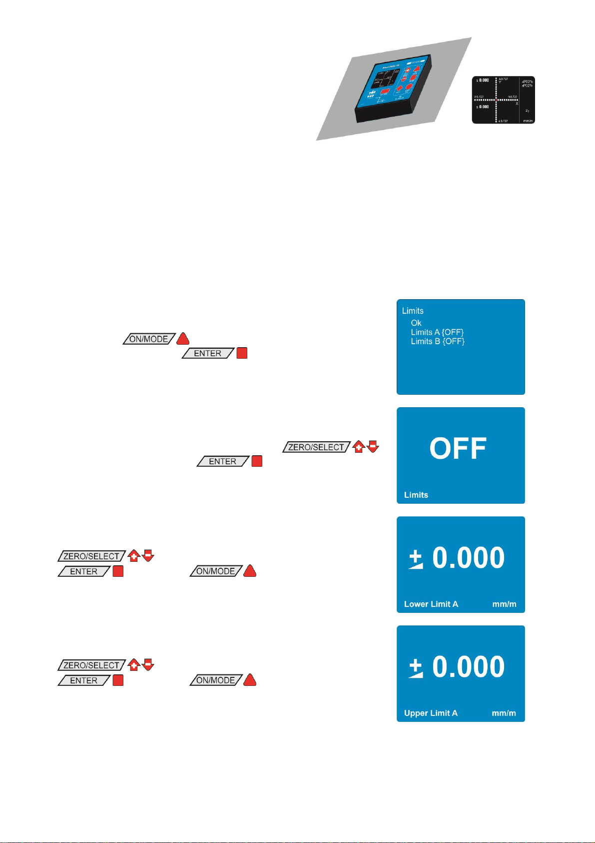
The value displayed is "0" and represents the
position of the reference defined.
Using the key select the menu item [LIMITS] and
confirm this selection with .
Switch the function [LIMITS] on or off using the
keys and confirm with the key .
You can now enter the lower limit. The value is adjusted using the
keys. Confirm the value with the key
. With the key the default value will be
recalled.
Now you can enter the upper limit. The value is adjusted using the
keys. Confirm the value with the key
. With the key the default value will be
recalled.
3.6 MEASURING WITH LIMITS / LIMITS
If you intend to set off an "Alarm" when a defined limit is exceeded this can be realised using the
function "LIMITS".
The function "LIMITS" allows defining an upper and a lower limit. If this set limit is exceeded
respectively under-run, a horizontal bar in the display will start blinking. A blinking bar above the
displayed value means that the upper limit has been exceeded. If the blinking bar is below the l ower
limit has been under-passed. Through the RS485 port a message will be sent.
page 24 of 65 pages
Page 25
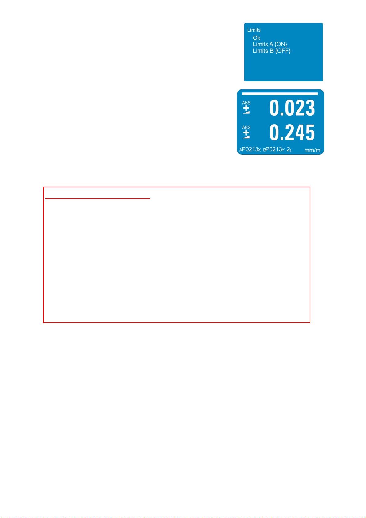
The measuring instrument will return to the measuring mode.
If during the measurement the lower respectively the upper limit is
exceeded a blinking horizontal bar will appear above respectively
below the inclination value. Via the RS485 port a respective
message will be sent.
Data format at the RS 485 interface
Upper Limit [sss xxxxxtt UL sn.nnnnnn sm.mmmmmm<cr>]
Lower Limit [sss xxxxxtt LL sn.nnnnnn sm.mmmmmm<cr>]
sss = 0 .. 255 - Laufnummer
xxxxxtt = Sensor Serial Number and Type
N2673Dx BlueLEVEL-2D X-Axis
N2673Dy BlueLEVEL-2D Y-Axis
sn.nnnnnn = +9.999999 - Positive Overrange
-9.999999 - Negative Overrange
other value - angular value in rad e.g. +0.226349
sm.mmmmmm = limit defined
It is possible to set the lower limit above the upper limit. In this case a respective message will be sent
via the RS485 port continuously.
page 25 of 65 pages
Page 26
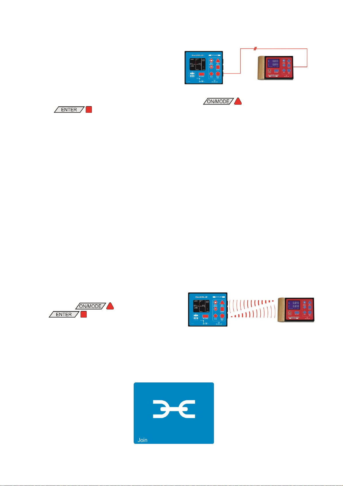
3.7 GROUPING OF INSTRUMENTS TO A MEASURING GROUP IN THE WIRELESS MODE
3.7.1 GROUPING VIA CABLE CONNECTION / JOIN
1. Connect all instruments to be grouped
(BlueLEVEL-2D and e.g. a BlueMETER
SIGMA or BlueTC) using the cables provided
and switch all instruments on.
2. Select on the BlueMETER the menu "JOIN" using the key. Confirm with the key
. All instruments connected are now searched and joined to a group.
3. After establishing the group a "REFRESH" will be performed.
4. After a successful grouping on both instruments the green LED "READY" will blink shortly as
many times as instruments are joined in the measuring group (including the own address).
5. For using the wireless mode (the wireless mode must be switched-on on each instrument) the
cables can now be removed. After removing the cables the measuring values will be "freezed"
for a short while and replaced by empty zeroes until, after successful connection, the measuring
values will be displayed again.
6. After successful connection the blue LED "LINK" will be lighting on all the instruments
connected.
3.7.2 GROUPING IN THE WIRELESS MODE / JOIN
With the function "JOIN" an instrument can be added to an existing group. During this procedure no
instrument must be connected by cables as otherwise the "JOIN" procedure for cables will be
performed. To make sure that the instrument does not belong to another group, it is advisable to
perform the function "LEAVE" first.
1. On the BlueLEVEL-2D select the menu "JOIN"
using the key. Confirm with
.
Set the second instrument also to the JOIN mode.
2. Searching
The two instruments are "searching" each other. During the searching procedure the green LED
on both instruments is lit continuously. The instruments remain in the "search" mode until they
have detected each other.
During the search process the following picture will be displayed:
Remark: The searching process may go on for several minutes in bad communication conditions.
page 26 of 65 pages
Page 27
3. Group connection
As soon as the two instruments have successfully detected each other the search process is
stopped and this is visualised by a rapid blinking (4 to 5 times per second) of the green LEDs on
both instruments. The joining can now
- be activated by using the key on one of the instruments
or
- the whole process may be cancelled by pressing the key.
If the LED "OFF" is blinking in red, a grouping is not possible (see chapter 3.7.3 / special case)
4. The green LED "READY" will blink shortly as many times as instruments are joined in the
measuring group (including the own address).
3.7.3 SPECIAL CASE "JOIN"
In case both instruments are already joined in different groups of instruments they do find each other
but they can not communi cate together. The red LED “OFF” is blinking. T he search process may be
cancelled by using the key .
If it is required to use one of the instruments in the new measurement group it is necessary to use the
mode “LEAVE” to cancel the existi ng connection.
3.7.4 UNHINGE AN INSTRUMENT FROM A GROUP USING THE FUNTION "LEAVE" / LEAVE
Each instrument may be unhinged individually from an existing measuring group.
PROCEDURE "LEAVE"
1. On the BlueLEVEL-2D select the menu "LEVAE" using the key.
Confirm with .
2. The BlueLEVEL-2D is now unhinged from the group and is no longer accessible via wireless
data transmission.
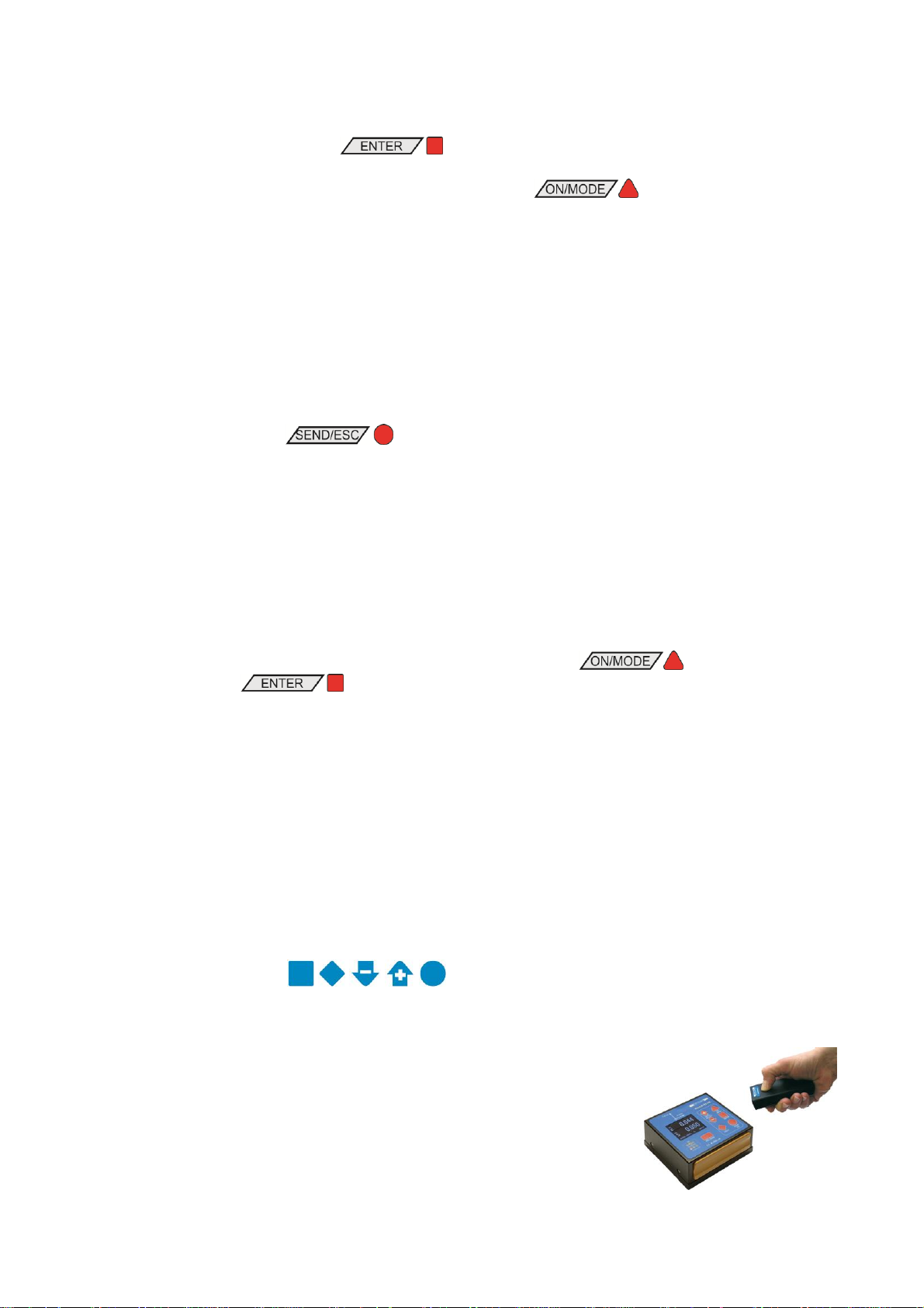
3.8 TEACH-IN of the IR-trigger (Zapper)
In order to eliminate interference of the zapper signals when several measuring groups are active in
the triggering range the IR trigger can be assigned to a specific measuring group by applying the
function TEACH-IN
Procedure TEACH-IN:
The measuring or display instrument must be started.
Keep one of the keys on the measuring or display instrument pressed
Point the trigger (IR Zapper) in the direction of the measuring or display instrument
Press the actuator key on the IR Zapper unti l both red IR LED’s are l ighting up.
This procedure must be done on all the measuring and display
instruments using the same IR triggering. When the instruments are
dispatched this procedure is already factory set standard.
page 27 of 65 pages
Page 28

4 OPTIONS
The options serve for entering the basic adjustments of the measuring instrument. The access to the
options can be protected with a PIN code in order to avoid unauthorised modifications.
The following options are available:
Option "Set PIN-Code"
With this option it is possible to block the entering of options with a PIN code.
Option "Display Settings"
With this option basic settings of the display, such as the brightness and colour pattern, are
possible.
Option "Logscale"
With this option the logarithmic scaling can be switched on or off.
Option "Programmable Keys"
With this option it is possible to switch the scale-functions of the keys <ZERO/SELECT> and the
functions of the key <ON/OFF> on or off.
Option "Functions ON/OFF"
With this option specific functions can be switched on or off. Functions switched off will no
longer appear in the main menu.
Option "Hide disabled Functions ON/OFF"
If this option is enabled, disabled functions will not be shown.
Option "Radio ON/OFF"
With this option the wireless data transmission can be activated or deactivated.
Option "Gravity"
With this function the correction of the gravitation can be switched on or off and the local
gravity force can be entered.
Option "Version"
With this option the version of the firmware will be displayed.
Option "Factory Reset"
A complete factory reset will set the instrument to the factory (default) settings as it has been
configured at the factory. All personal settings are lost.
Option "Self Test"
A function check of the instrument will be performed.
page 28 of 65 pages
Page 29
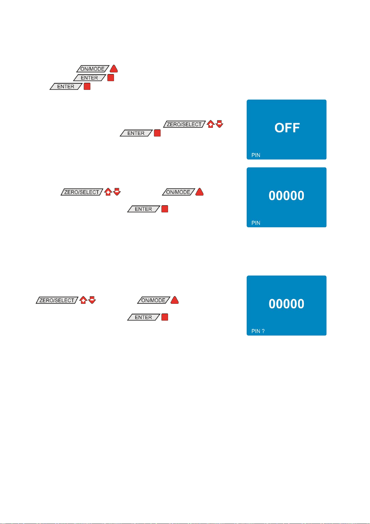
4.1 SET PIN-CODE
Using the key select the menu point [Options] and
confirm with . Select now [Set Pin Code] and confirm
with
Switch the blocking of options with the keys to
ON and confirm with the key .
You can now enter your PIN code. The value can be adjusted using
the keys . With the key the
standard value 00000 will be recalled.
Confirm your entry with the key .
The measuring instrument will change back to the measuring mode.
Entering the PIN code: The value can be adjusted using the keys
. With the key the standard value
00000 will be recalled.
Confirm your entry with the key .
In order to protect the settings of the BlueLEVEL-2D against unauthorised changes you have the
possibility to block the entering of options with a PIN code.
If the option PIN code is activated, the code must be entered before the list of options will be shown.
As a factory setting the PIN code is deactivated. The default value is 00000.
4.2 DISPLAY SETTINGS
The brightness of the display, the brightness in the energy safe mode and the colour pattern can be
adjusted individually. The BlueLEVEL-2D will work in the energy safe mode as long as no external
power supply is connected and it is powered by batteries. The brightness is indicated as a percentage
of the maximum brightness. As the power consumption is considerably reduced with a reduced
brightness, it is recommended to use in the energy safe mode a brightness of 50 % (default).
With the colour pattern the background colour can be adjusted. The colour of the fonts changes
according to the brightness of the background between white and black. Standard background is blue.
page 29 of 65 pages
Page 30
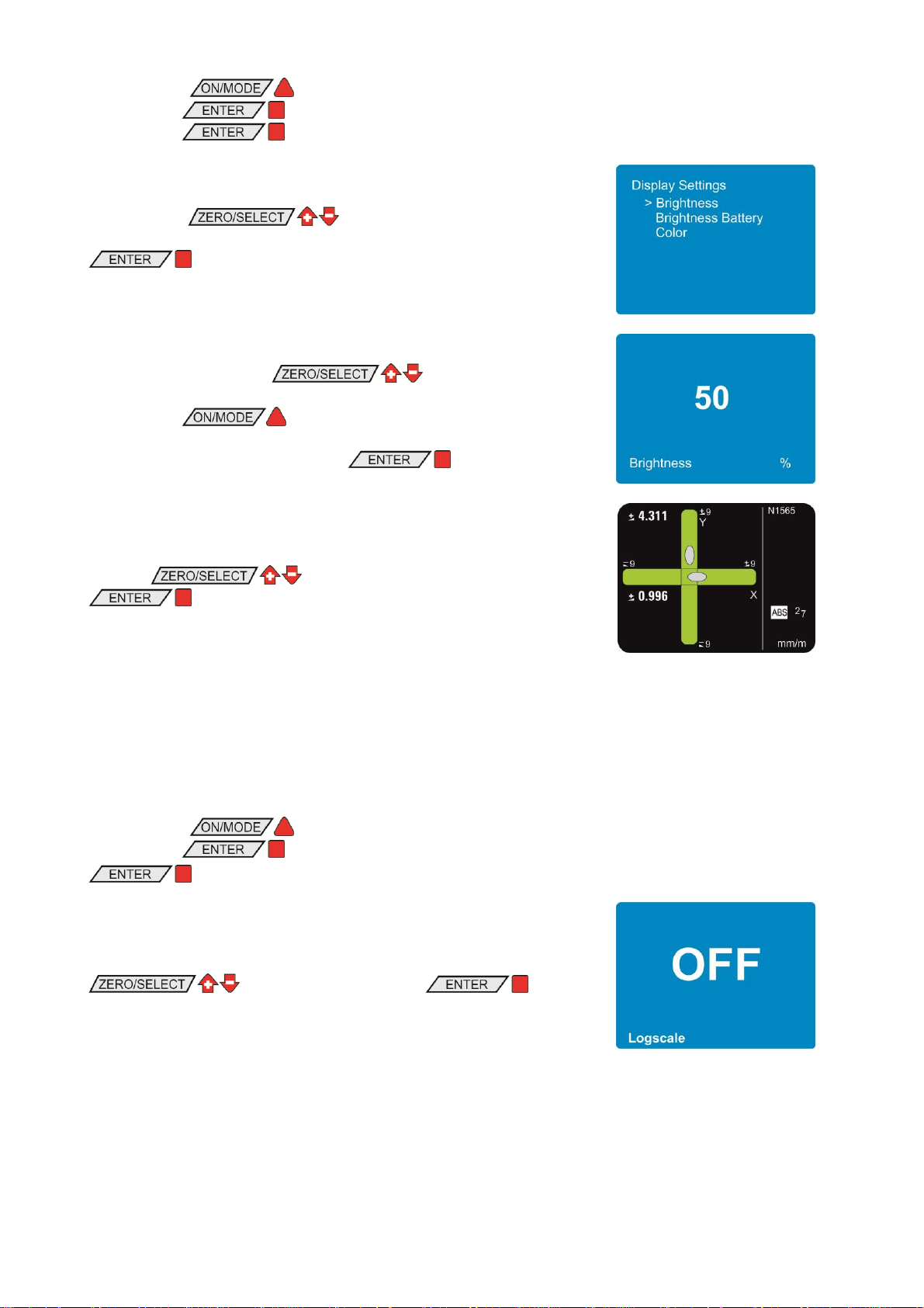
Using the key select the menu point [Options] and
confirm with . Select now [Display Settings] and
confirm with
With the keys select the display option you
would like to change and confirm the selection with the key
.
In the brightness adjustments you can increase or reduce the
brightness using the keys . The range is from
10% to 100%.
With the key the default value of 50% will be
recalled.
Confirm the new value with the key .
In the colour adjustments you can select the colour preferred using
the keys . Confirm your choice with the key
.
The measuring instrument will return to the measuring mode.
Using the key select the menu point [Options] and
confirm with . Select now [Logscale] and confirm with
Switch the logarithmic scaling ON or OFF using the keys
and confirm with the key .
The measuring instrument will return to the measuring mode.
4.3 LOGSCALE
With this option the logarithmic scaling can be switched on or off.
page 30 of 65 pages
Page 31
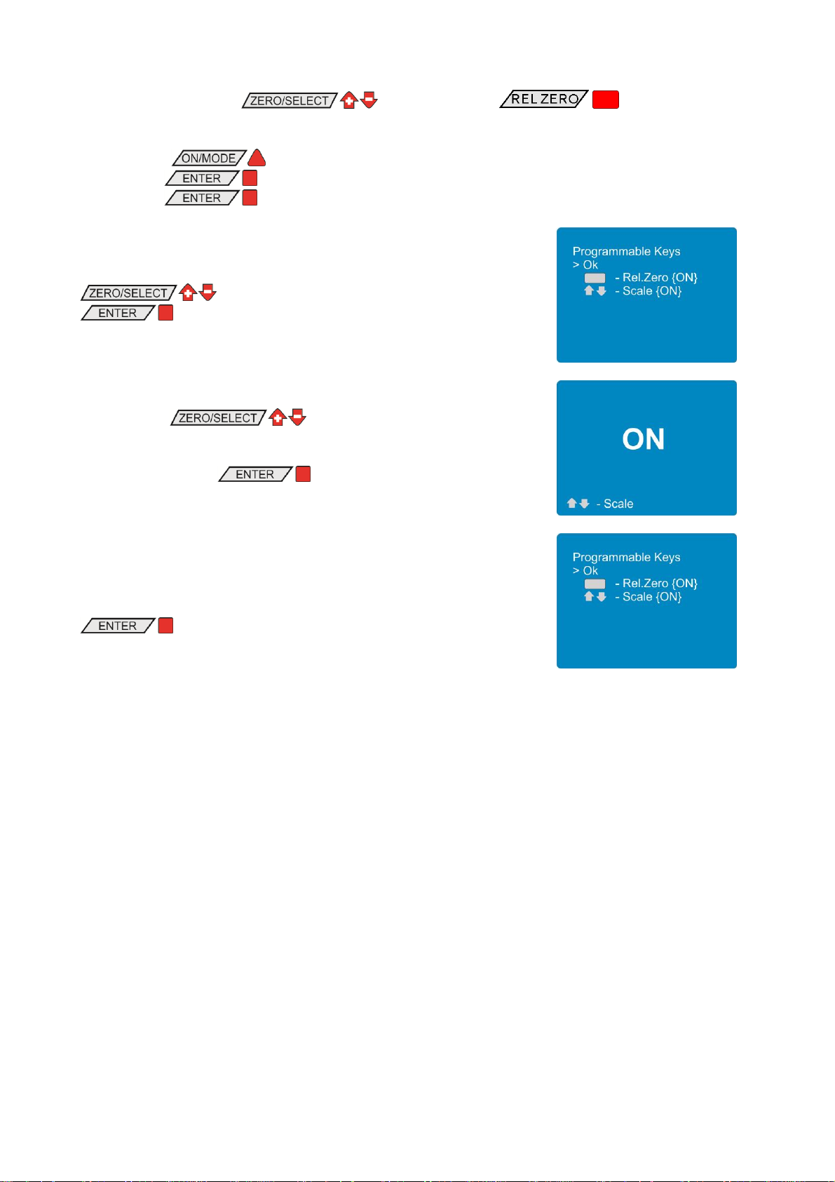
4.4 PROGRAMMABLE KEYS
Using the key select the menu point [Options] and
confirm with . Select now [Programmable keys] and
confirm with
Select the key you want to activate or deactivate using the keys
and confirm your choice with the key
.
With the keys you can switch the selected key
ON or OFF. In the display the selected status will be shown. ON
means activated, OFF means deactivated.
Confirm with the key .
The list of the programmable keys will be shown again. For switching
another key on or off, repeat the procedure as described above.
In order to store the settings select "Ok" and confirm with the key
.
The measuring instrument will return to the measuring mode.
The function of the keys as well as the key can be switched on
or off.
page 31 of 65 pages
Page 32
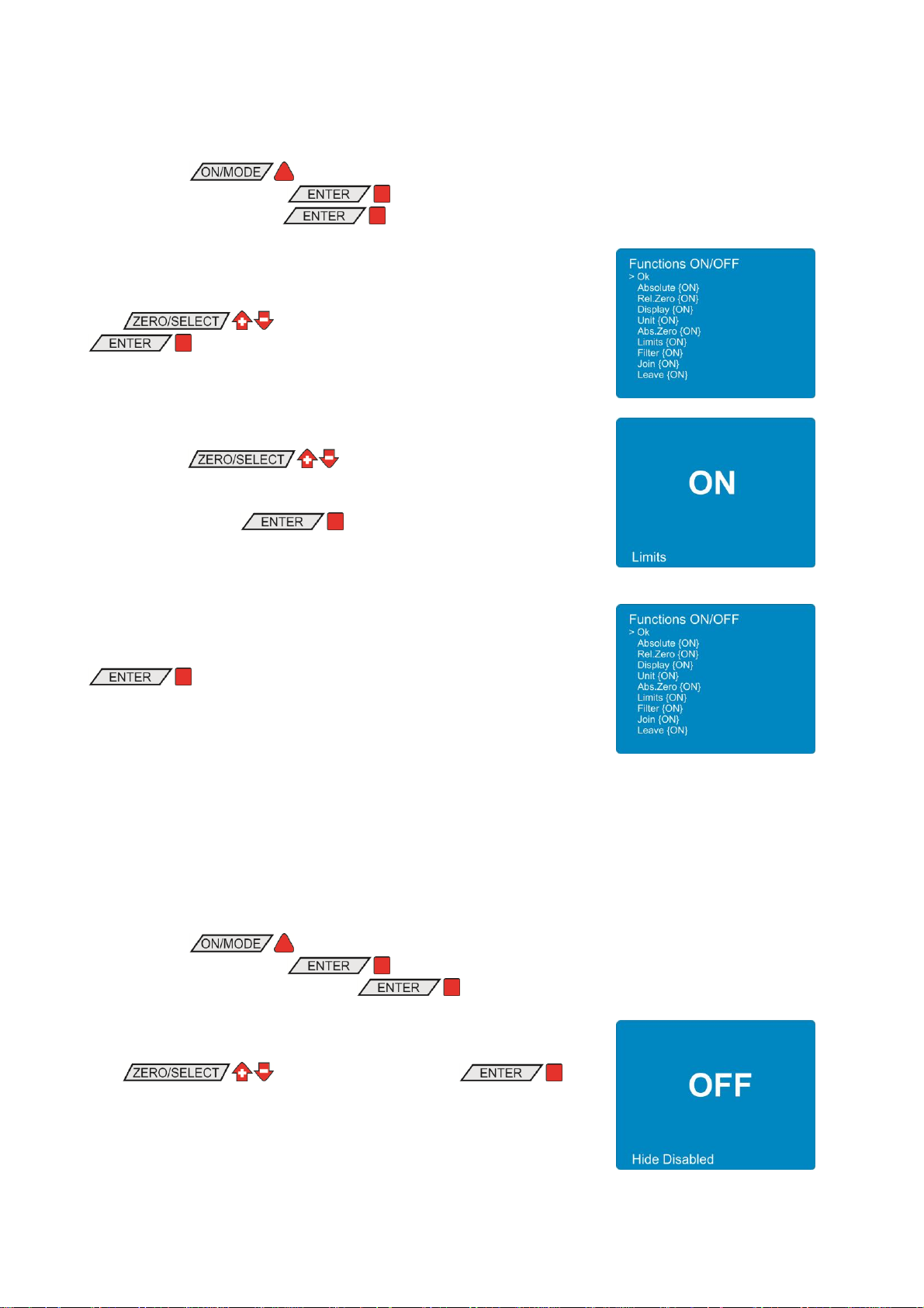
4.5 FUNCTIONS ON/OFF
Using the key select the menu point [Options] and
confirm your selection with . Select now [Functions
ON/OFF] and confirm with
Select the function you want to switch on respectively off with the
keys and confirm your selection with the key
.
With the keys you can switch the selected
function ON or OFF. In the display the selected status will be shown.
ON means enabled, OFF means disabled.
Confirm with the key .
The list of the switchable functions will be shown again. For
switching another function on or off, repeat the procedure as
described above.
In order to store the settings select "Ok" and confirm with the key
.
The measuring instrument will return to the measuring mode.
Using the key select the menu point [Options] and
confirm your selection with . Select now [Hide disabled
Functions ON/OFF] and confirm with
Switch the adjustment "Hide disabled functions" ON or OFF with the
keys and confirm with the key .
The measuring instrument will return to the measuring mode.
The menu functions provided can be switched on respectively off. Thus the menu displayed can be
adjusted to the needs of the user.
4.6 HIDE DISABLED FUNCTIONS ON/OFF
This adjustment allows you to hide the functions disabled. The list of functions will only show those
functions which are enabled. If this adjustment is not activated, disabled functions will be shown in the
list of functions in grey fonts.
page 32 of 65 pages
Page 33
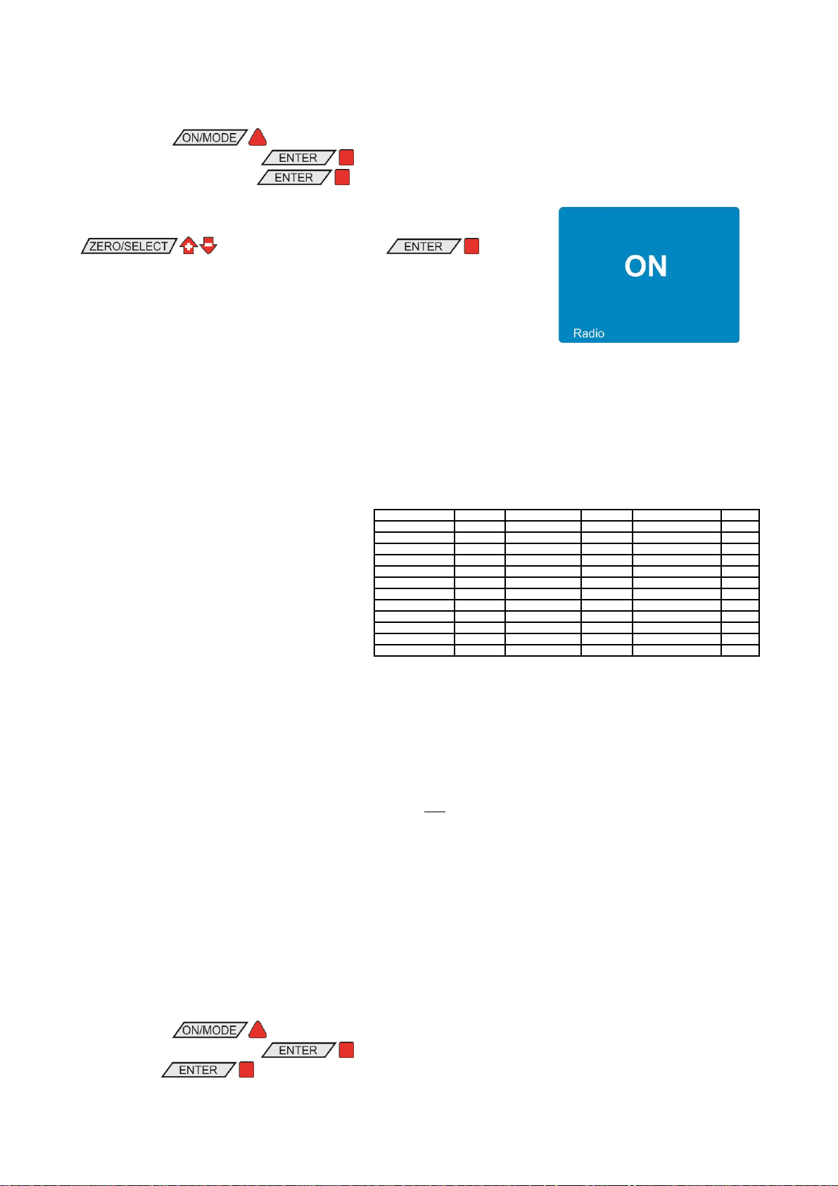
4.7 RADIO ON/OFF
Using the key select the menu point [Options] and
confirm your selection with . Select now [Radio
ON/OFF] and confirm with
Switch the wireless transmission ON or OFF using the keys
and confirm with the key .
The measuring instrument will return to the measuring mode.
m
m
c
eff
g
g
sinarcsin
Using the key select the menu point [Options] and
confirm your selection with . Select now [Gravity] and
confirm with .
Amsterdam
9.813
Istanbul
9.808
Paris
9.809
Athens
9.807
Havana
9.788
Rio de Janeiro
9.788
Auckland, NZ
9.799
Helsinki
9.819
Rome
9.803
Bangkok
9.783
Kuwait
9.793
San Francisco
9.800
Brussels
9.811
Lisbon
9.801
Singapore
9.781
Buenos Aires
9.797
London
9.812
Stockholm
9.818
Calcutta
9.788
Los Angeles
9.796
Sydney
9.797
Cape Town
9.796
Madrid
9.800
Taipei
9.790
Chicago
9.803
Manila
9.784
Tokyo
9.798
Copenhagen
9.815
Mexico City
9.779
Vancouver, BC
9.809
Nicosia
9.797
New York
9.802
Washington, DC
9.801
Jakarta
9.781
Oslo
9.819
Wellington, NZ
9.803
Frankfurt
9.810
Ottawa
9.806
Zurich
9.807
This adjustment allows you to switch the wireless data transmission on or off.
4.8 GRAVITATION
The inclination displayed by the BlueLEVEL-2D is based on the gravitation. Around the globe the
gravitation is, however, not constant but it varies with the latitude and with the height above sea level.
Furthermore variations of the density in the lithosphere cause additional local deviations.
As an example the gravity at sea level is
9,78033 m/s2 at the equator ,
9,80620 m/s2 at 45 degree of
latitude,
9,83219 m/s2 at the poles.
In the table to the right the values of
gravity for some cities are listed.
The BlueLEVEL-2D has been calibrated
at the head office of WYLER AG. The
inclinations displayed are exact only in
this location. In different places the
displayed value must be corrected. If the
correction of the local gravity is switched on, the inclination measured will be corrected accordingly
before the value is displayed.
The correction is calculated according the following formula:
whereas
gc gravity at the place of calibration
α
displayed angle at place of measurement
m
gm gravity at the location of measurement
α
effective angle
eff
In order to switch the correction of the local gravity on respectively off, proceed as follows:
page 33 of 65 pages
Page 34
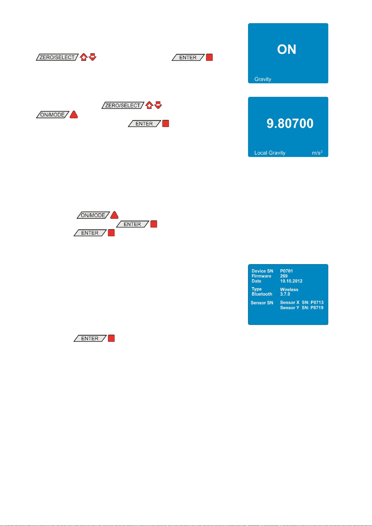
Switch the correction of the gravitation ON or OFF using the keys
and confirm with the key .
.
Now you can enter the value of the local gravity. The value is
adjusted with the keys . With the key
the standard value 9.80700 m/s2 will be recalled.
Confirm your entry with the key .
The measuring instrument will return to the measuring mode.
Using the key select the menu point [Options] and
confirm your selection with . Select now [Version] and
confirm with .
The following information will be displayed:
Serial number of the instrument
Number of the Firmware
Release date of the Firmware
Type of the instrument (Wireless / Cable)
Version of the Bluetooth module
Serial number of the integrated sensor
Measuring range
With the key this display will be left.
The measuring instrument will return to the measuring mode.
4.9 VERSION FIRMWARE
With this option information about the firmware installed and the configuration can be displayed.
page 34 of 65 pages
Page 35
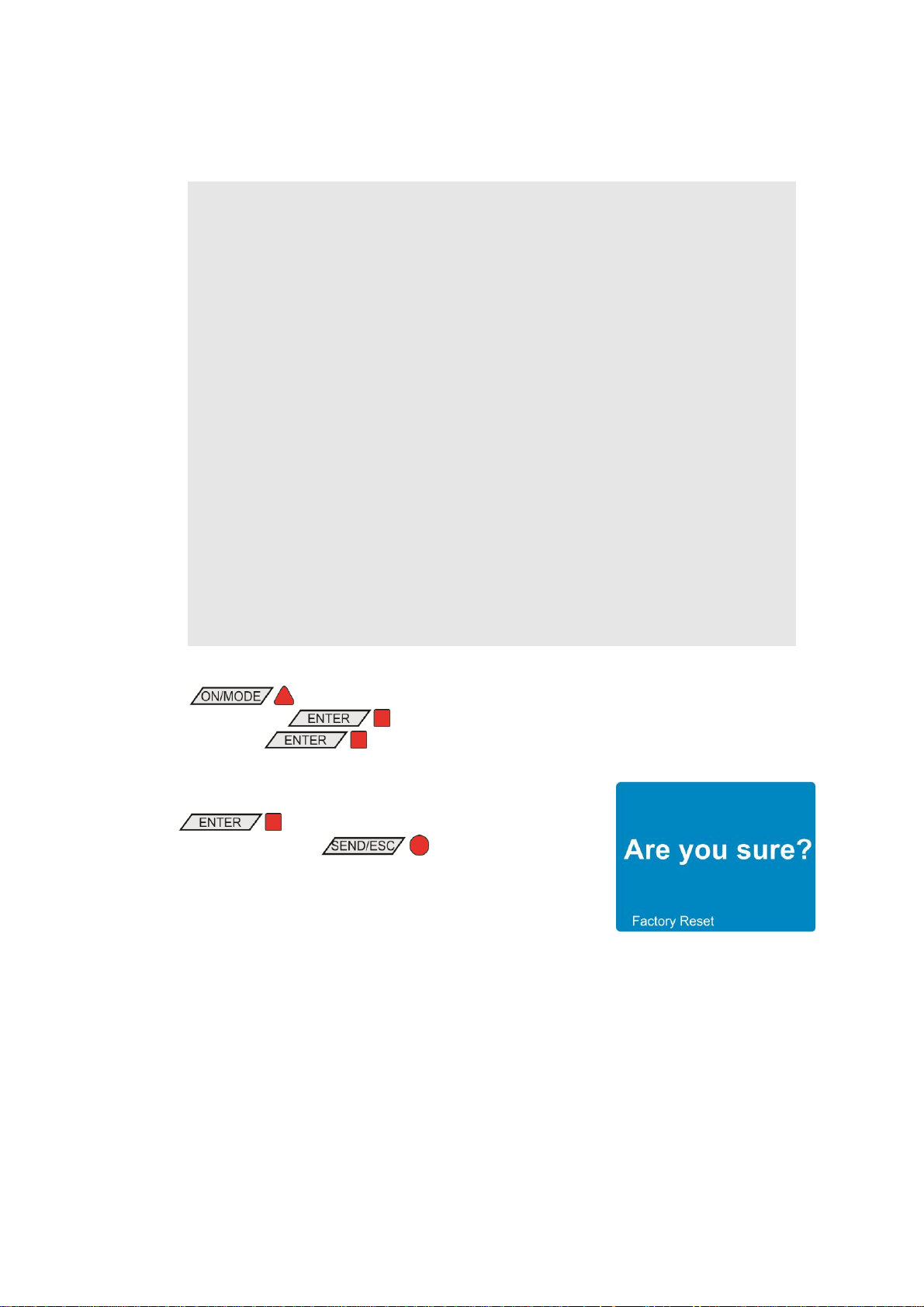
4.11 FACTORY RESET
Using the key select the menu point [Options] and
confirm your selection with . Select now [Factory
Reset] and confirm with .
In order to prevent a resetting by error the question "Are you sure?"
will appear. If you really want to delete all personal settings, press
now the key .
After 10 seconds or with the key the instrument will
return to the measuring mode.
The measuring instrument returns to the measuring mode.
A complete factory reset will reset the instrument to the state as it has been configured at the factory.
All personal settings are lost.
The BlueLEVEL-2D will be set to the following standard configuration:
Standard-Values:
measuring mode: absolute
measuring unit: DEC xx°xx'xx"
relative base: 1000 mm
absolute Zero point (ZERO-OFFSET): 0
relative Zero point (REL ZERO-OFFSET): 0
Filter No. 3
Display numeric display
Limits OFF
Upper Limit 0
Lower Limit 0
Scale maximum range
Join not joined
Pin Code OFF; Code = 00000
Display Settings Colour Blue;
Saturation 100%;
Saturation Power Save 50%;
Logscale OFF
Programmable Keys all keys enabled
Functions all functions enabled
Hide disabled Functions OFF
Radio ON, if available
Gravitation OFF; value = 9.807 kg·m/s2
page 35 of 65 pages
Page 36
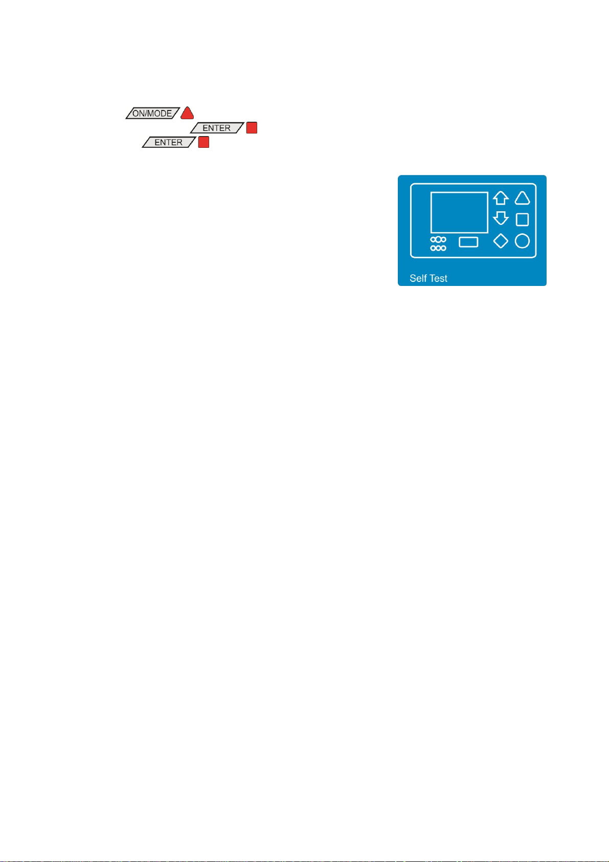
4.12 FUNCTION CHECK
Using the key select the menu point [Options] and
confirm your selection with . Select now [Self Test]
and confirm with .
In the display a simplified design of the front foil of the BlueLEVEL2D will be shown. If any key or the IR zapper is pressed, the real
LEDs as well as those on the display will lit. In addition the key
pressed will be marked. Each key will create an individual pattern.
Thereby the real LEDs and those on the display must be identical. If
this is not the case, either a key or an LED is defective.
After 10 seconds without activating any key the instrument will leave
the function check mode.
The measuring instrument will return to the measuring mode.
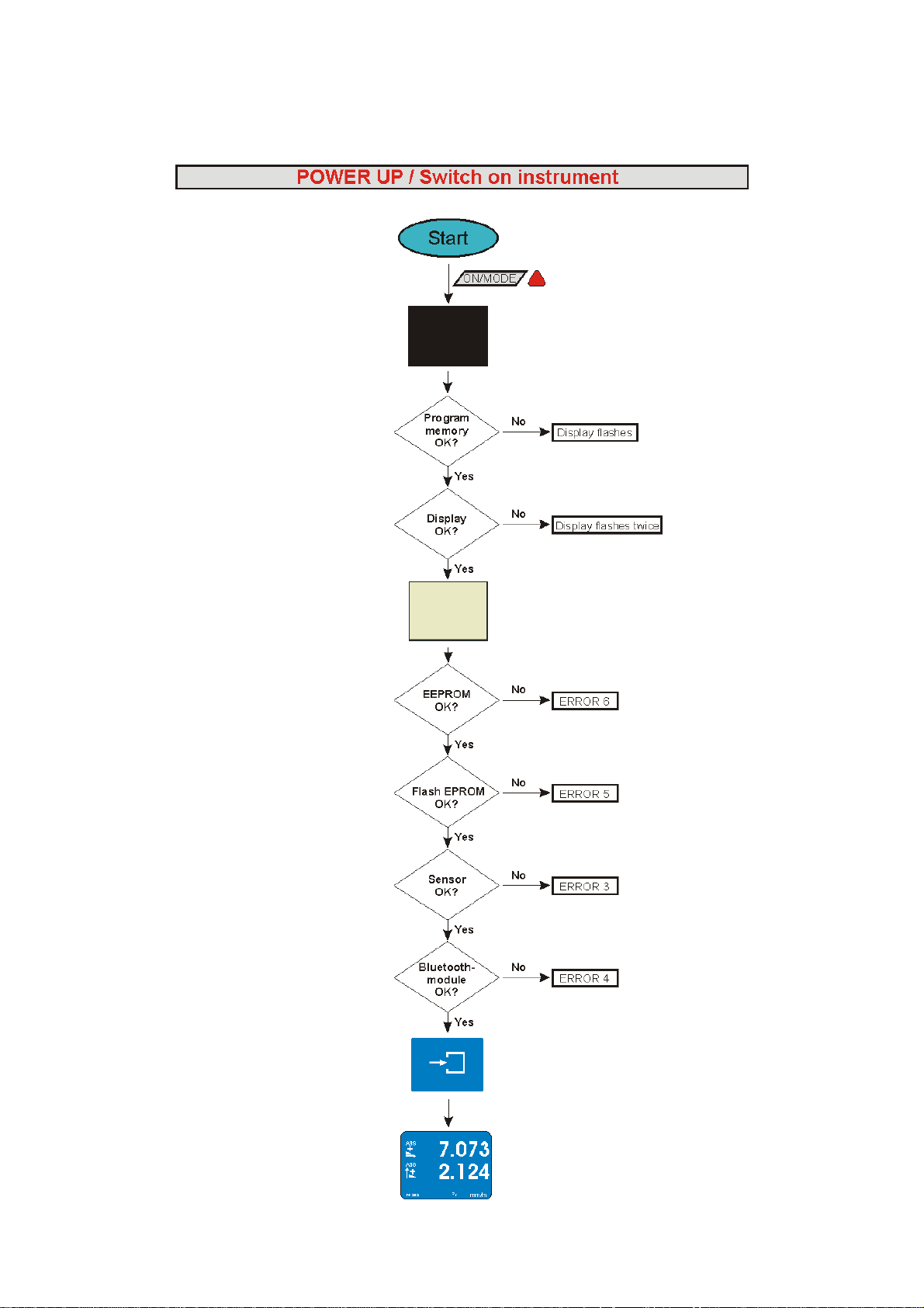
At the start of the instrument a system test will be performed, checking the most important functions.
In addition to this test the functions of the keys and of the LEDs can be checked.
page 36 of 65 pages
Page 37
APPENDICES
A FLOAT CHARTS GENERAL
A1 START THE INSTRUMENT / ON/OFF
page 37 of 65 pages
Page 38
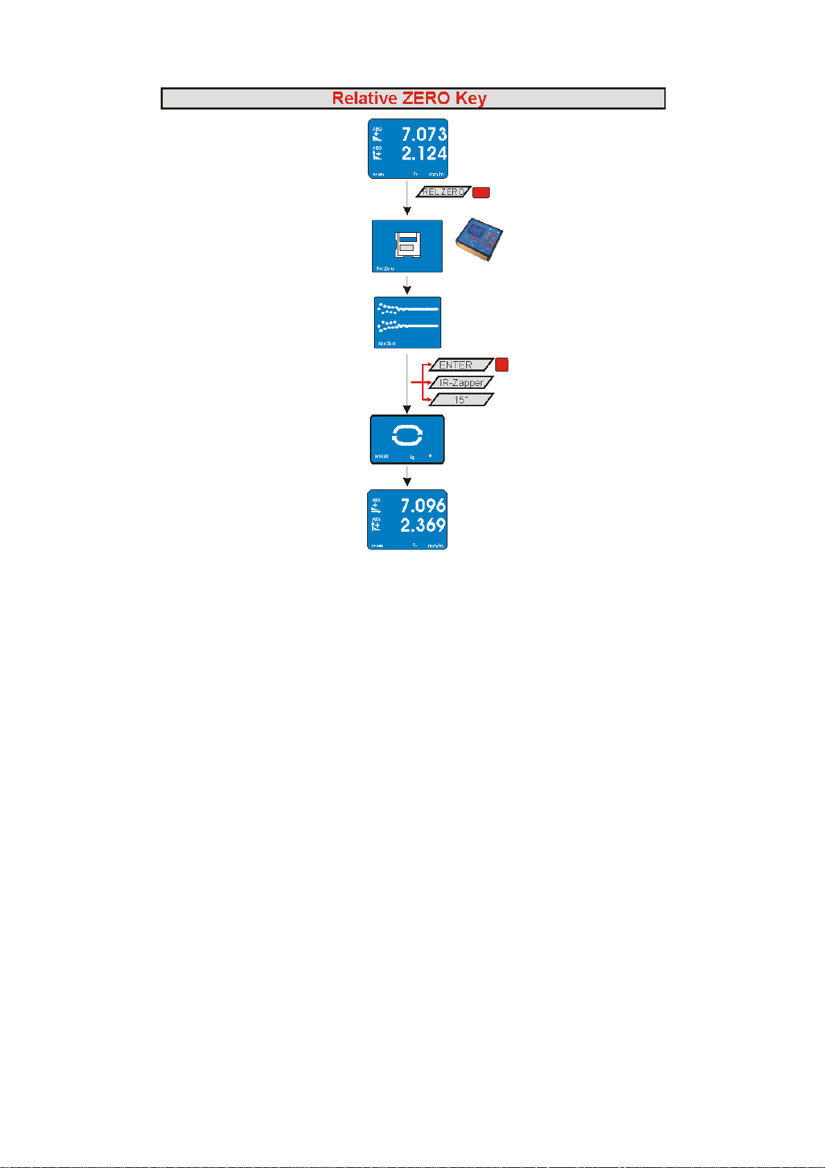
A2 KEY REL.ZERO
page 38 of 65 pages
Page 39
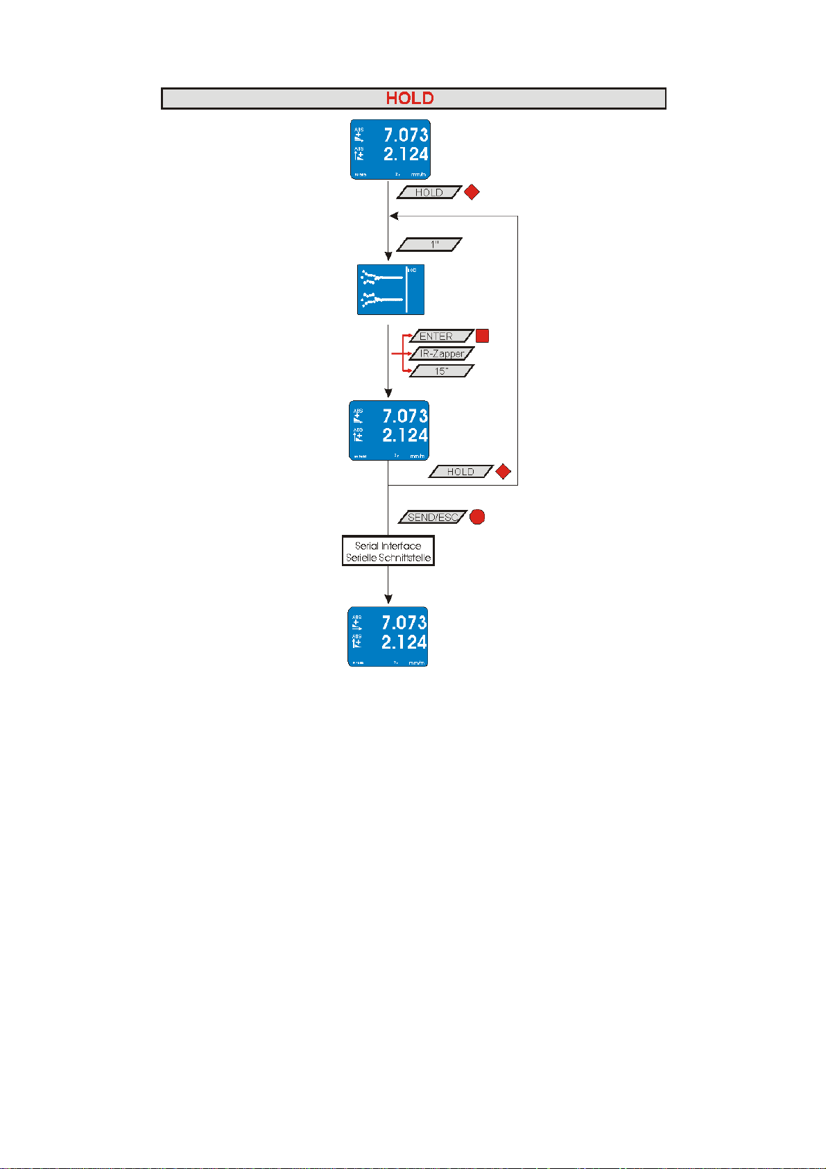
A3 KEY HOLD, FREEZING OF A MEASURING VALUE / HOLD
page 39 of 65 pages
Page 40
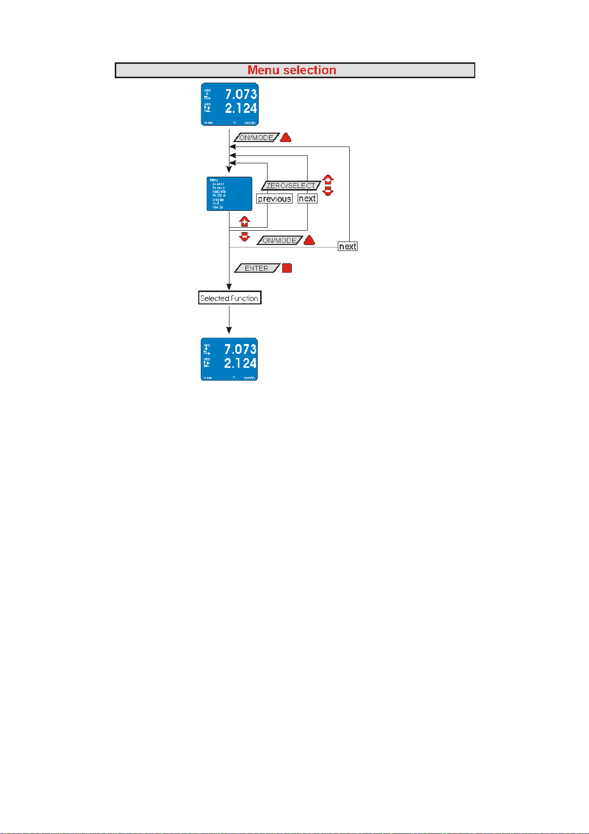
A4 MENU SELECTION
page 40 of 65 pages
Page 41
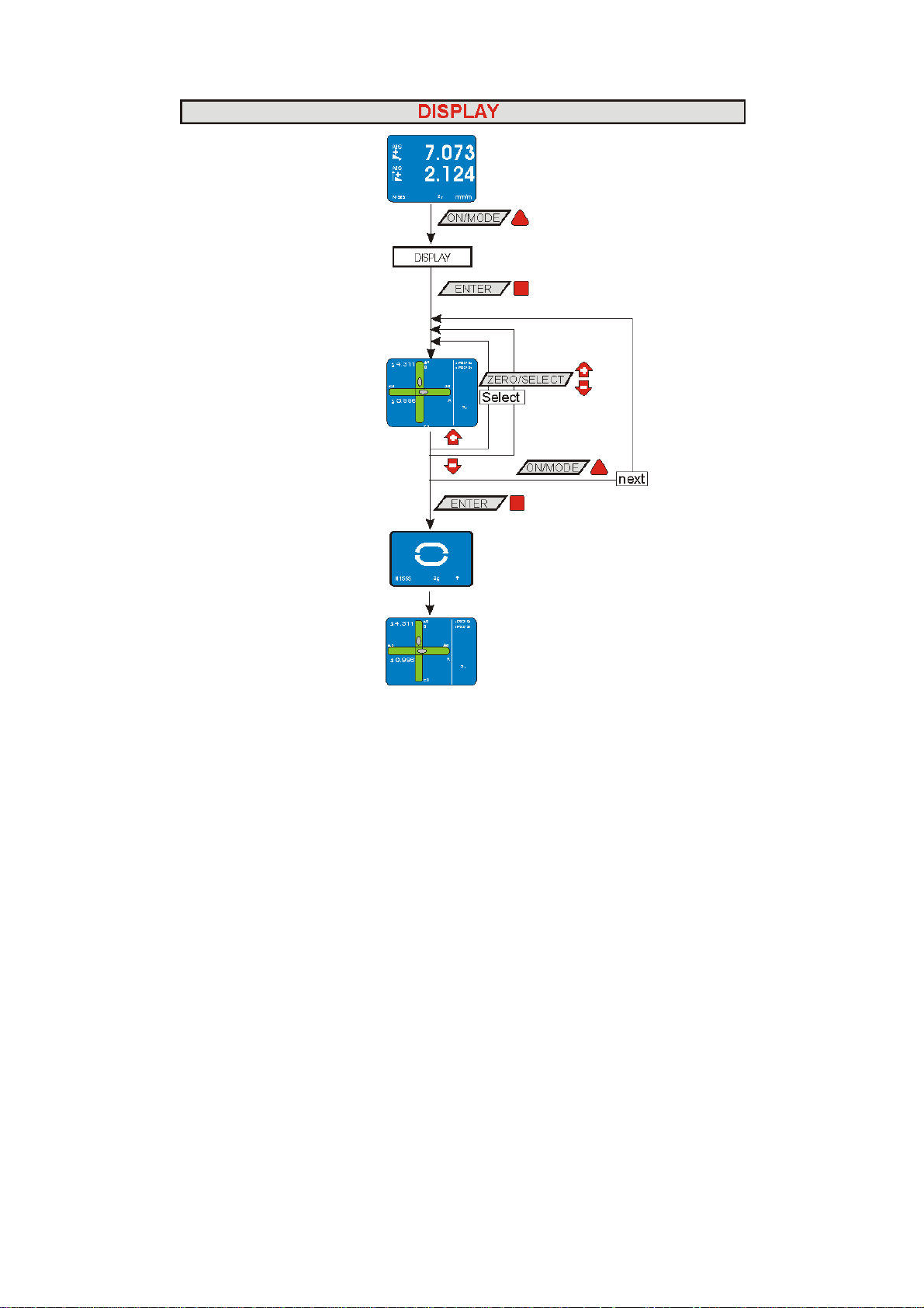
A5 ADJUSTMENT OF THE DISPLAY / DISPLAY
page 41 of 65 pages
Page 42
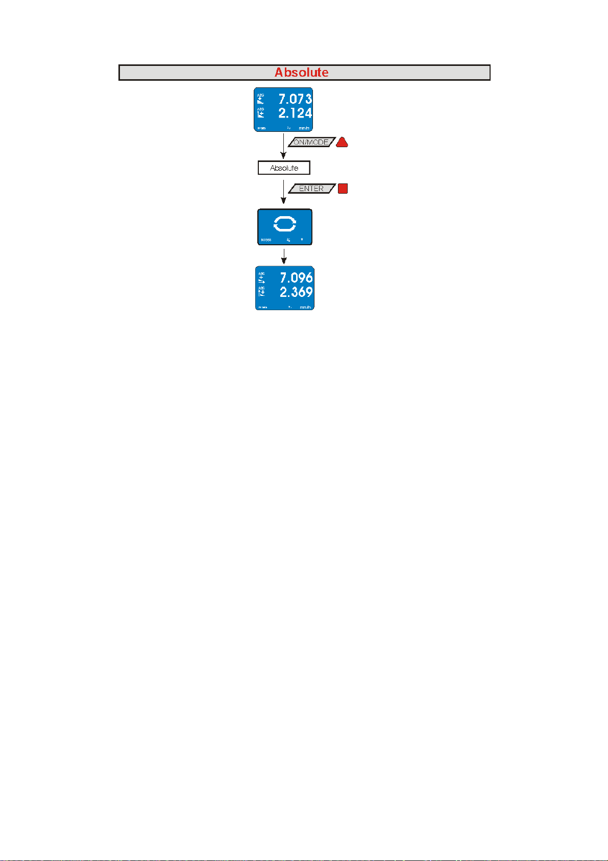
A6 MEASUREMENT ABSOLUTE / MODE ABSOLUTE
page 42 of 65 pages
Page 43
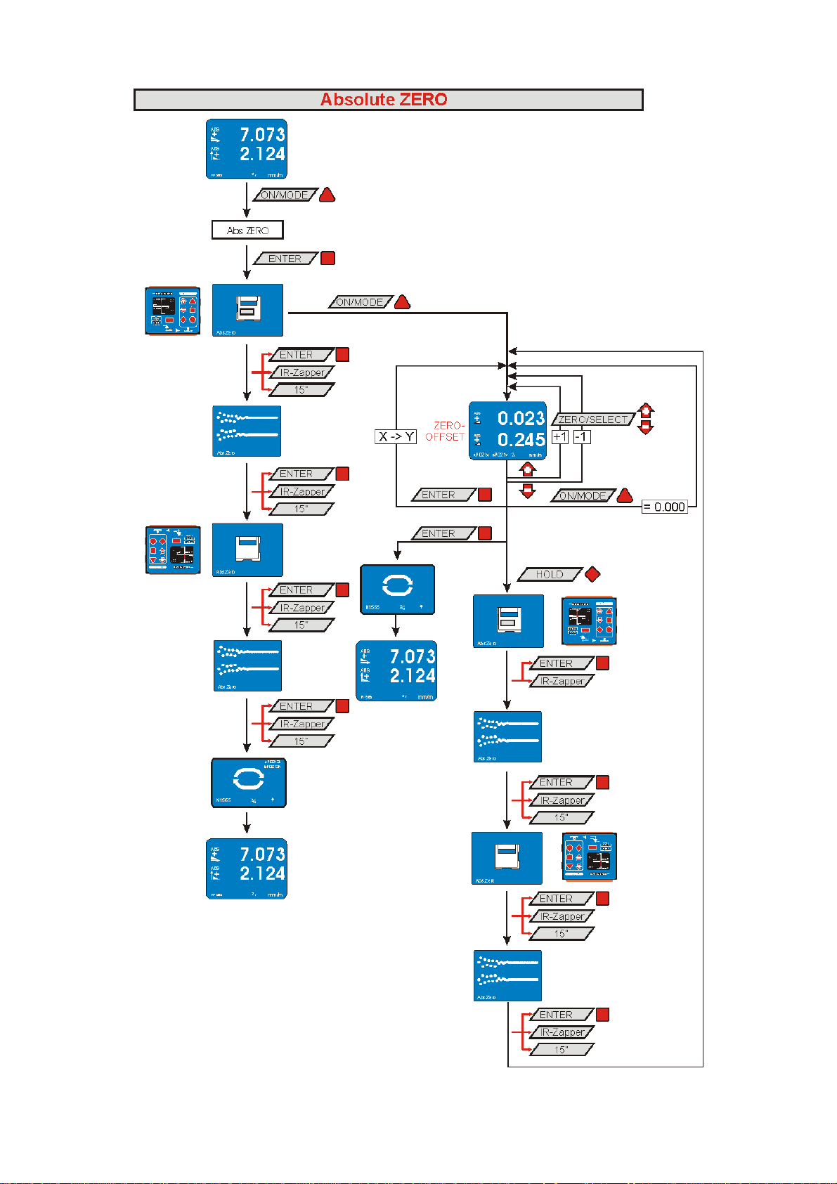
A7 MEASURING ABSOLUTE CONSIDERING THE ZERO OFFSET / MODE ABSOLUTE ZERO
page 43 of 65 pages
Page 44
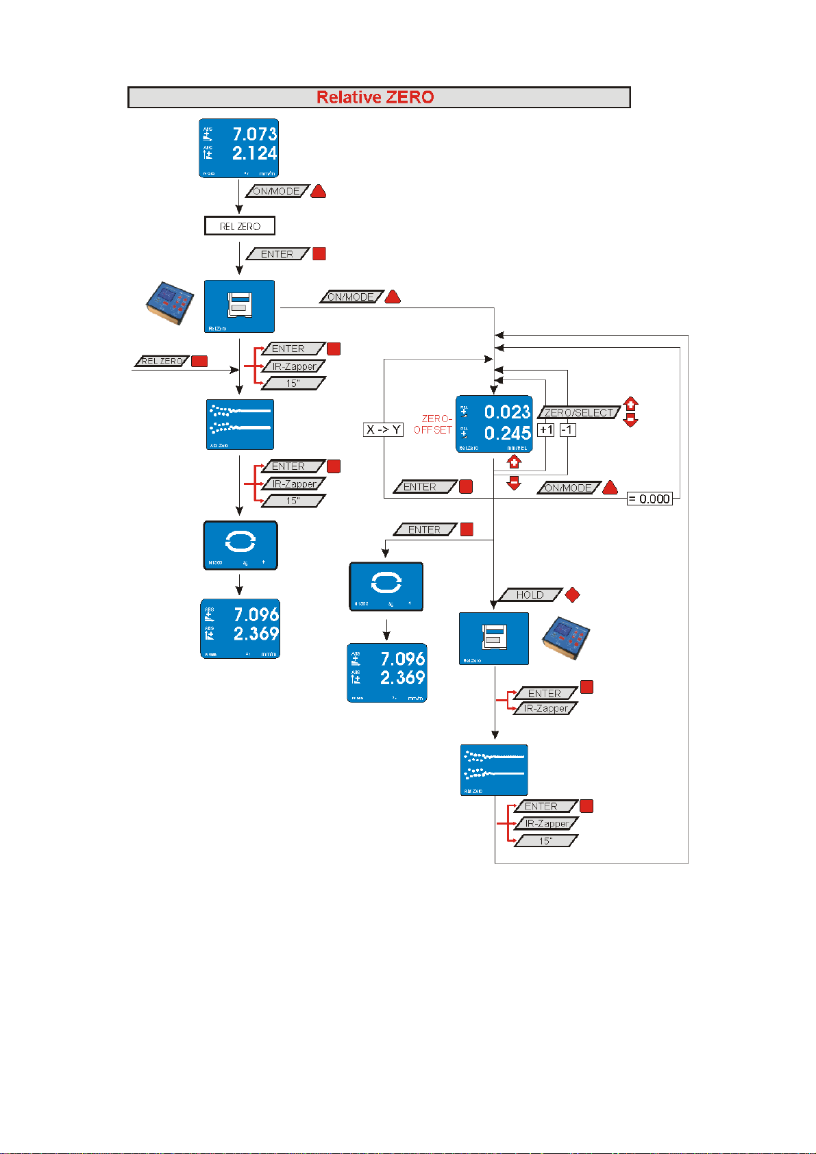
A8 MEASURING RELATIVE / MODE REL ZERO
page 44 of 65 pages
Page 45
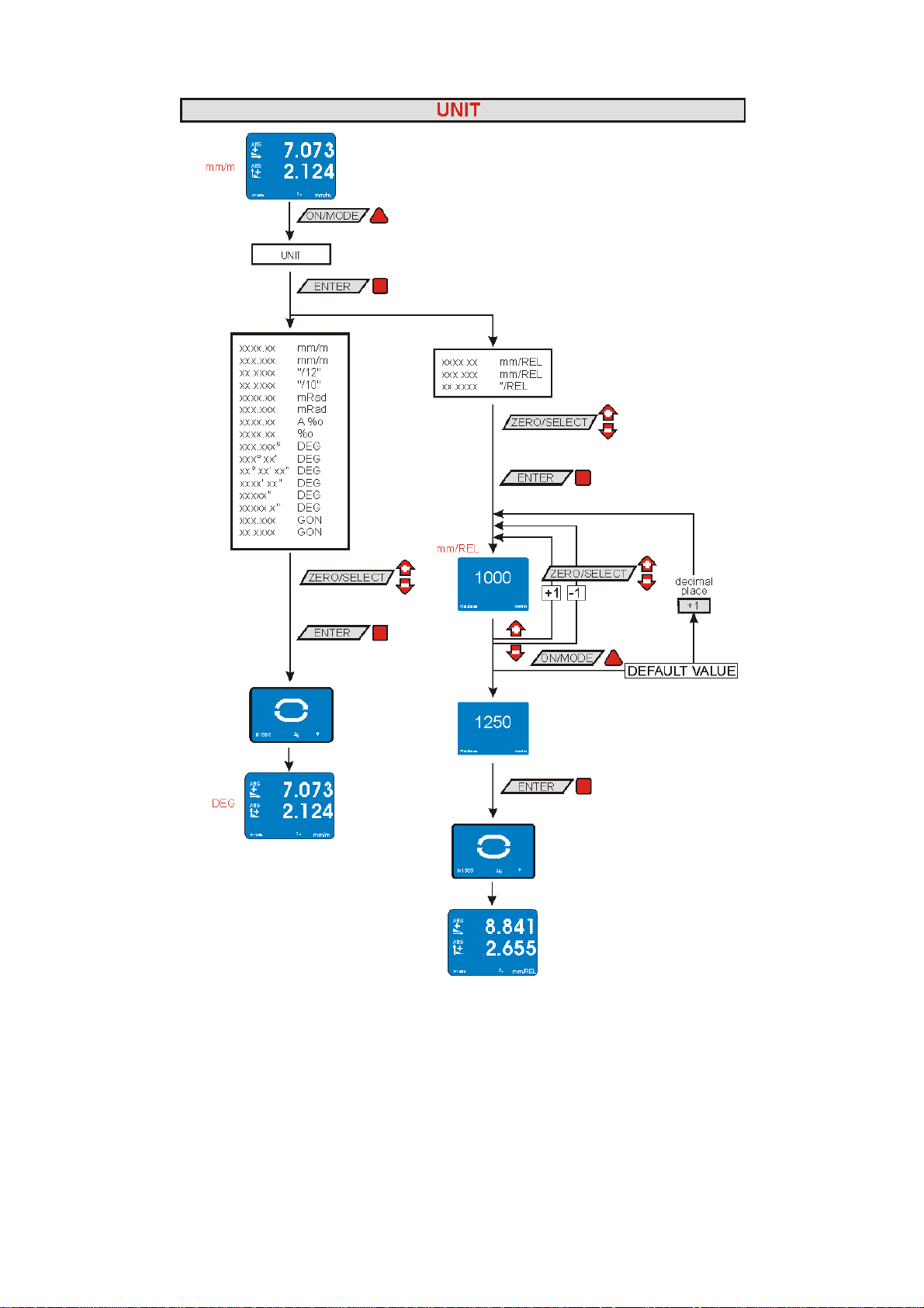
A9 ADJUSTMENT OF THE MEASURING UNIT / UNIT
page 45 of 65 pages
Page 46
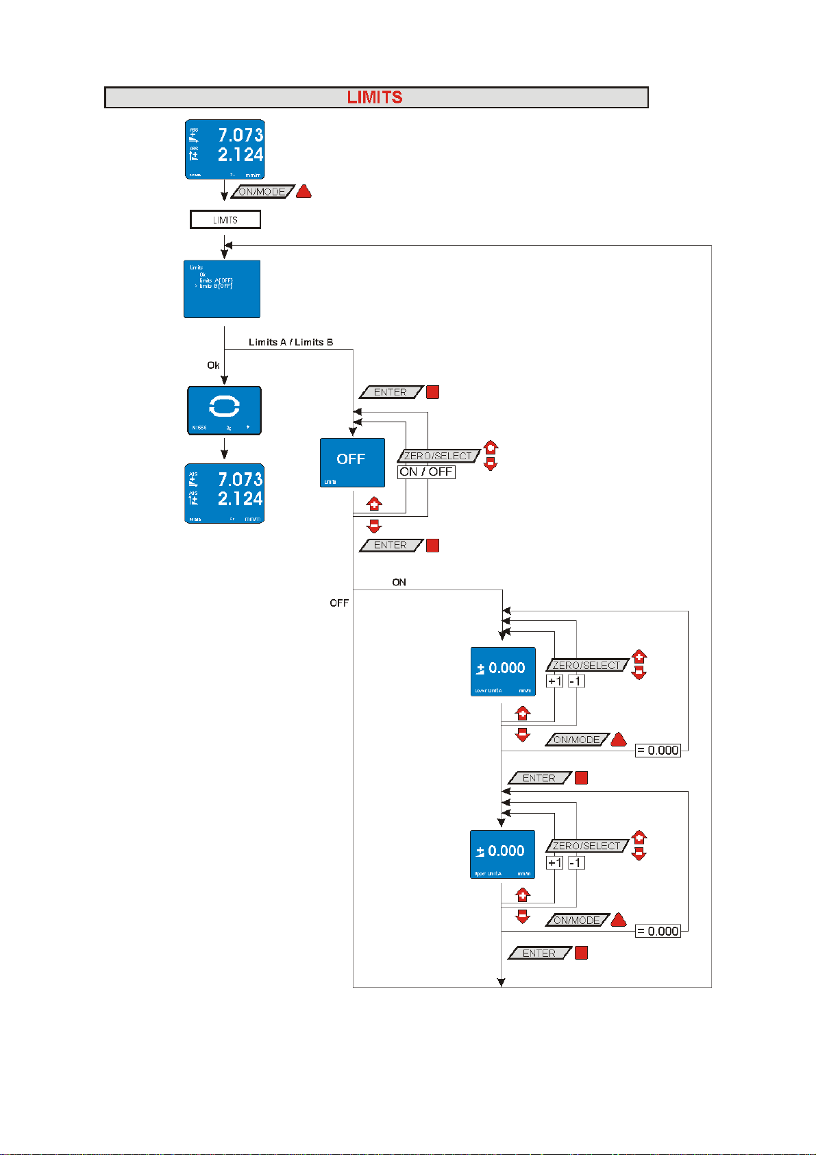
A10 SETTING OF LIMITS / LIMITS
page 46 of 65 pages
Page 47
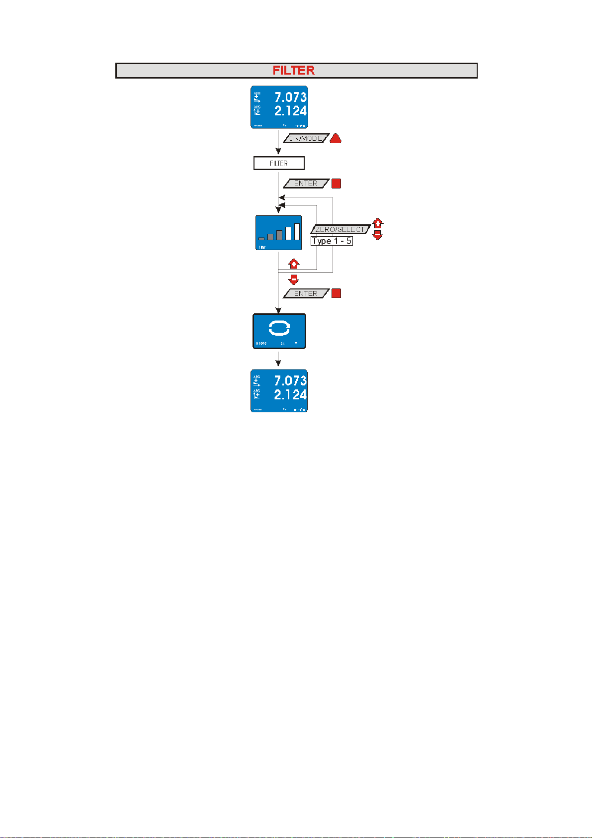
A11 ADJUSTMENT OF FILTER TYPES / FILTER
page 47 of 65 pages
Page 48
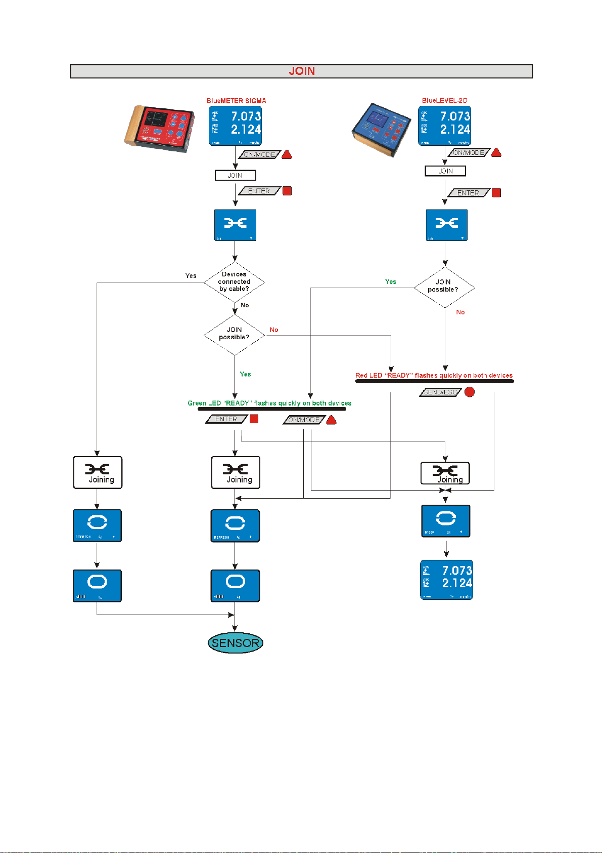
A12 GROUPING OF INSTRUMENTS WITH WIRELESS TRANSMISSION / JOIN
page 48 of 65 pages
Page 49
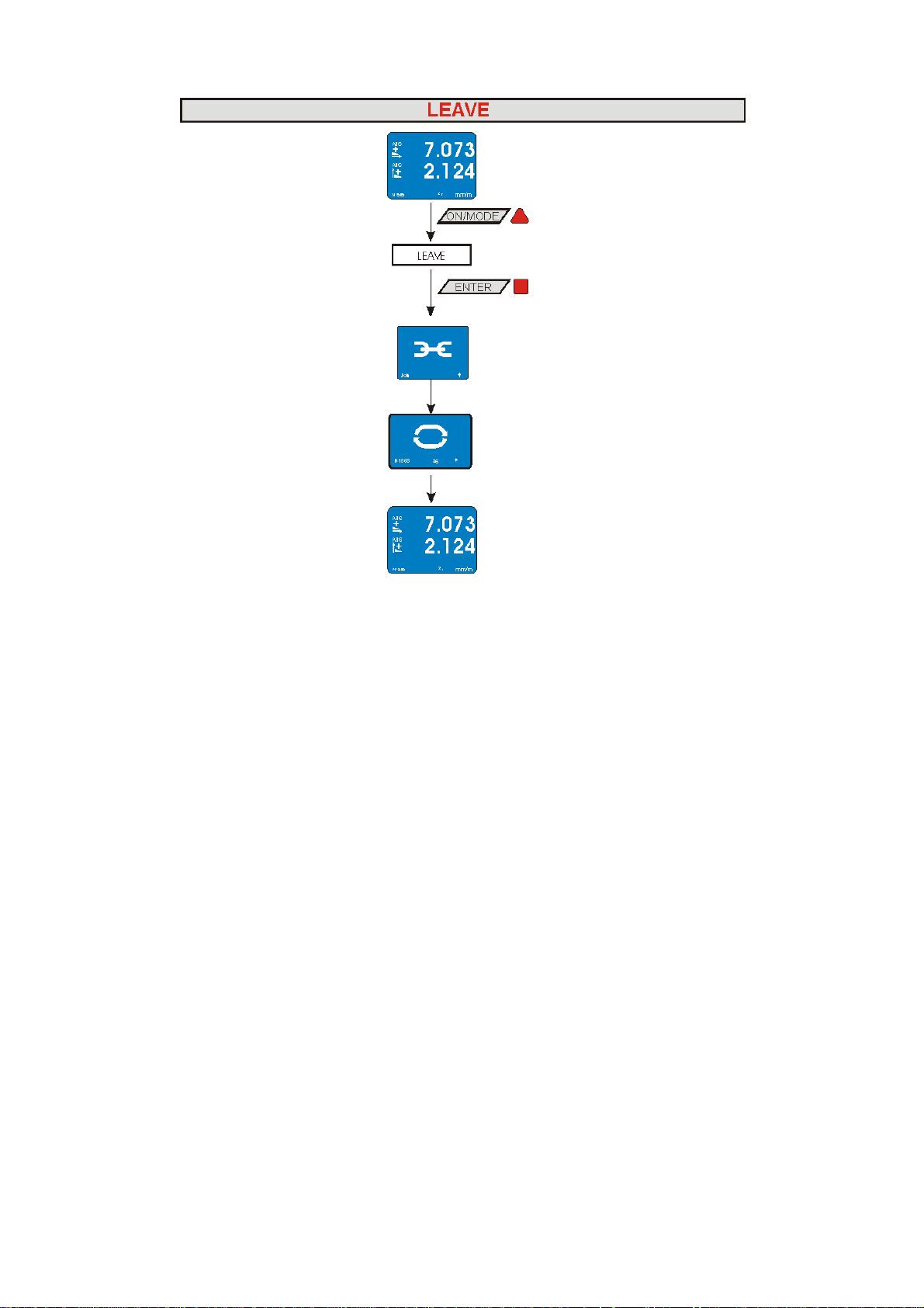
A13 LEAVING A GROUP OF INSTRUMETNS / LEAVE
page 49 of 65 pages
Page 50
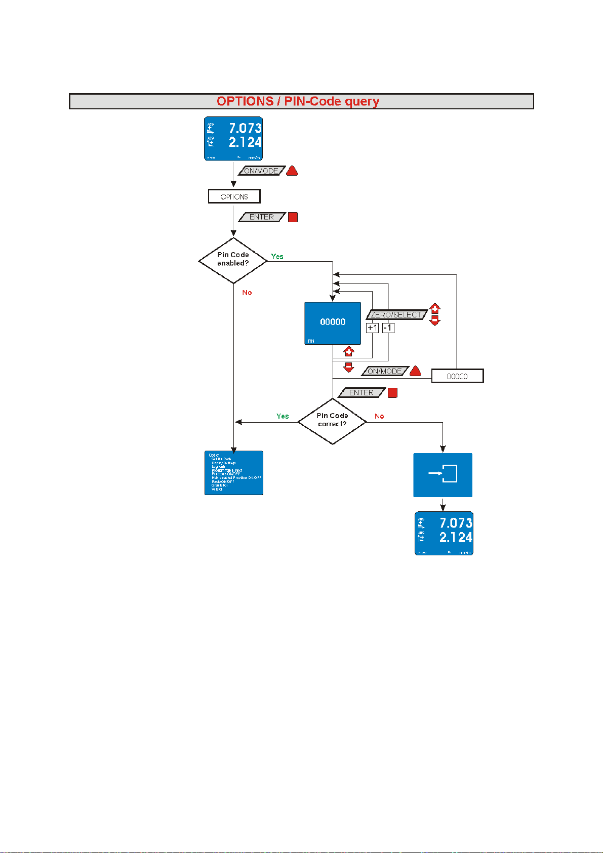
B FLOAT CHARTS OPTIONS
B1 PIN-CODE-QUERY FOR ACCESS TO THE OPTIONS
page 50 of 65 pages
Page 51
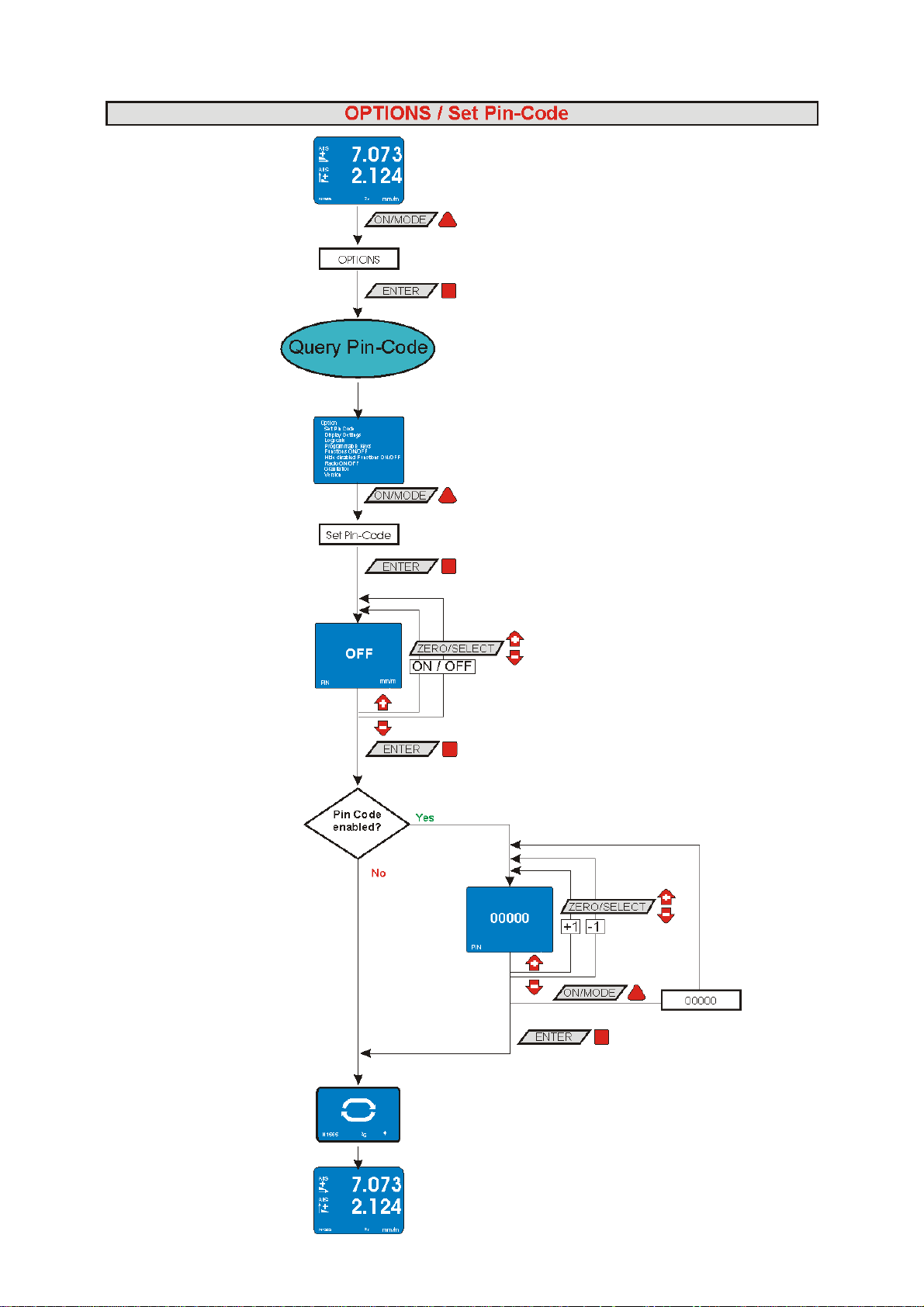
B2 SET PIN CODE
page 51 of 65 pages
Page 52
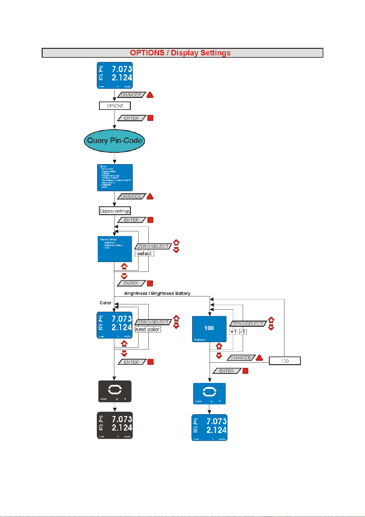
B3 DISPLAY SETTINGS
page 52 of 65 pages
Page 53
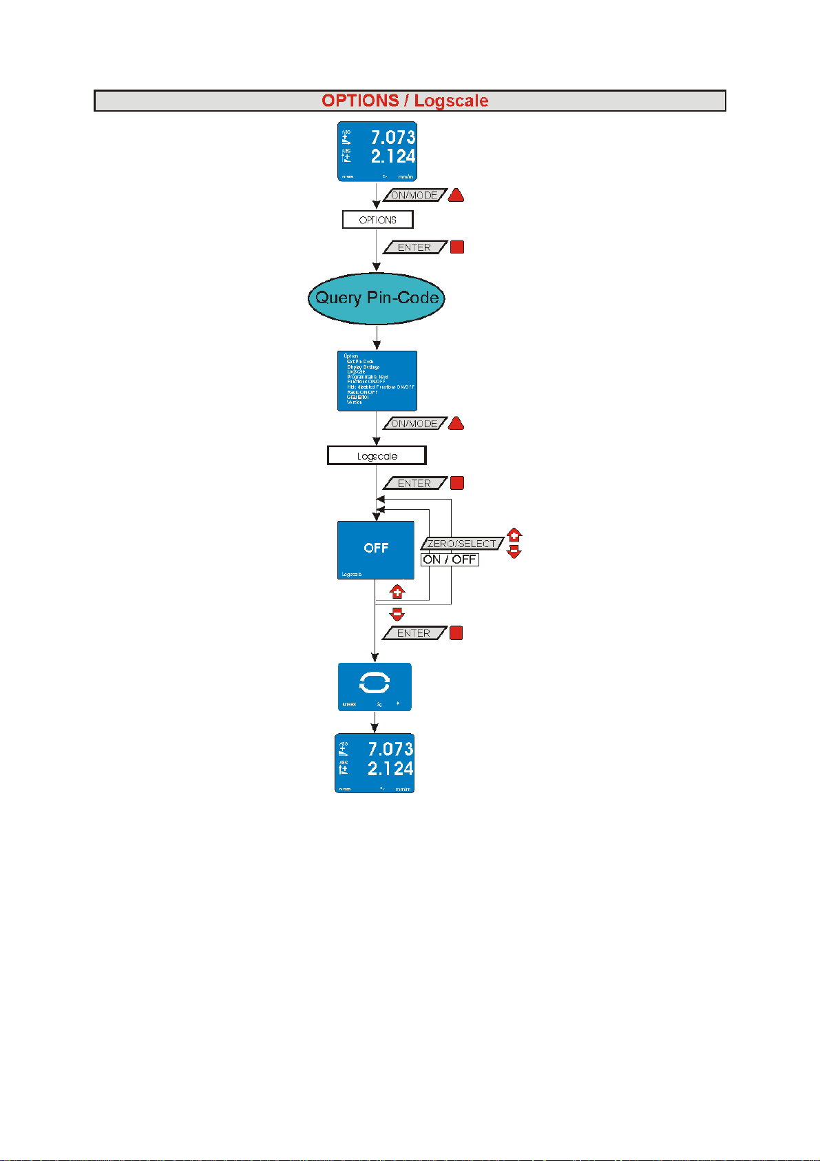
B4 LOGARITHMIC SCALE ON/OFF / LOGSCALE ON/OFF
page 53 of 65 pages
Page 54
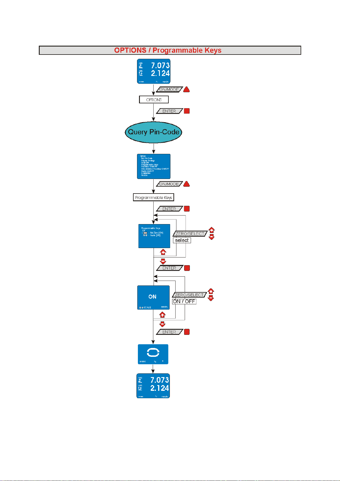
B5 PROGRAMMABLE KEYS "REL ZERO" AND "ZERO/SELECT" /
PROGRAMMABLE KEYS
page 54 of 65 pages
Page 55
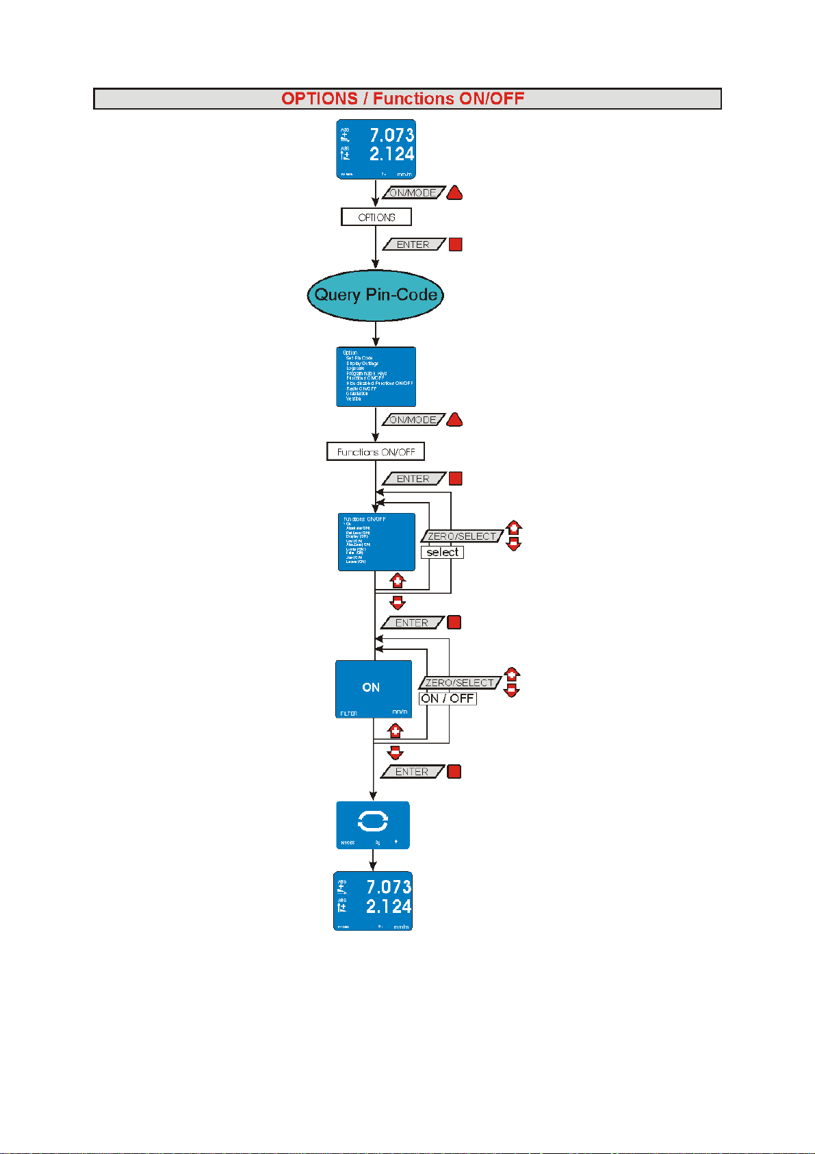
B6 SWITCHING FUNCTIONS ON OR OFF / FUNCTIONS ON/OFF
page 55 of 65 pages
Page 56
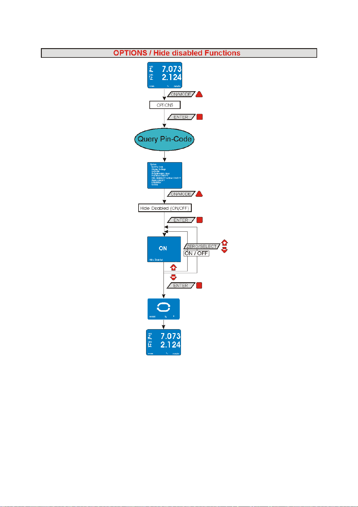
B7 SWITCHING THE HIDING OF DISABLED FUNCTIONS ON OR OFF /
HIDE DISABLED FUNCTIONS ON/OFF
page 56 of 65 pages
Page 57
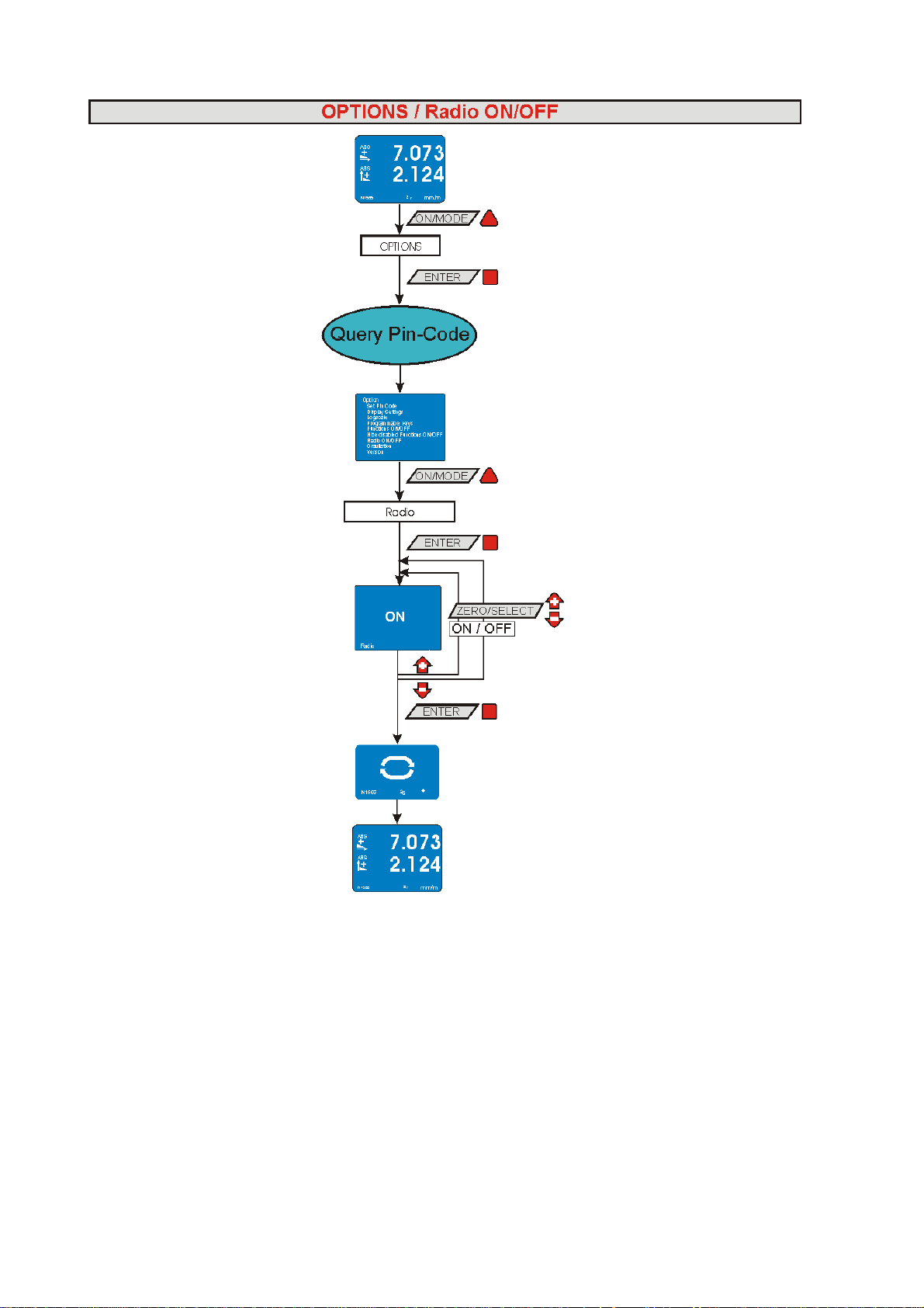
B8 SWITCH THE WIRELESS TRANSMISSION ON OR OFF / RADIO ON/OFF
page 57 of 65 pages
Page 58
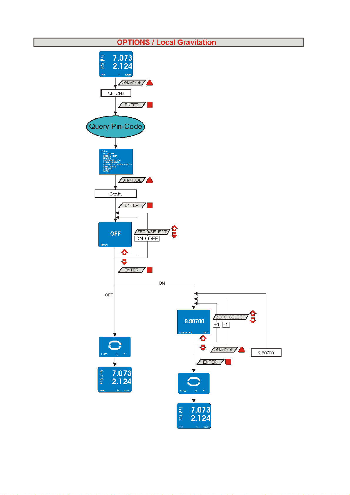
B9 SWITCH THE COMPENSATION OF GRAVITY ON OR OFF / GRAVITATION COMPENSATION
page 58 of 65 pages
Page 59
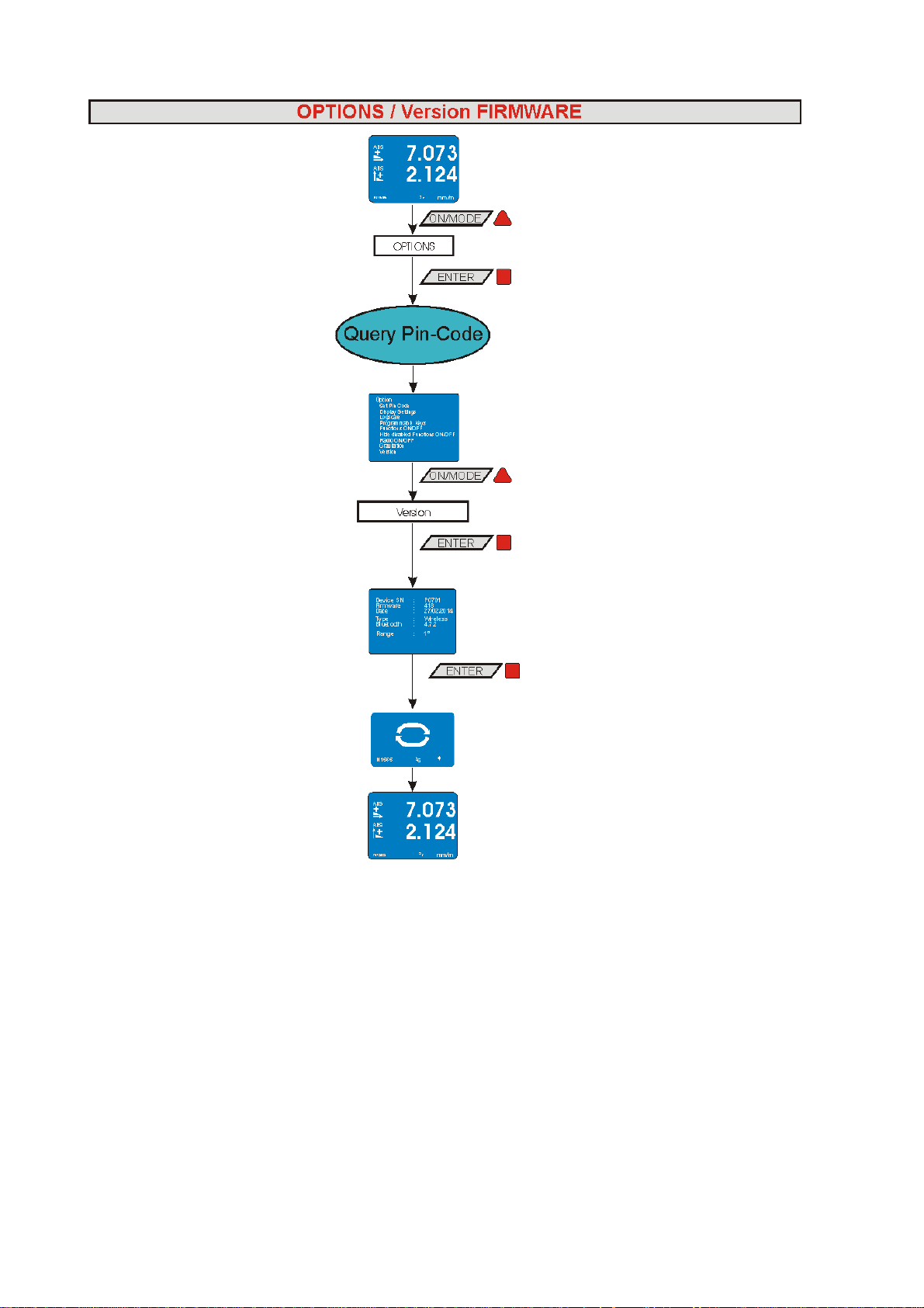
B10 DISPLAY THE FIRMWARE-VERSION / VERSION FIRMWARE
page 59 of 65 pages
Page 60
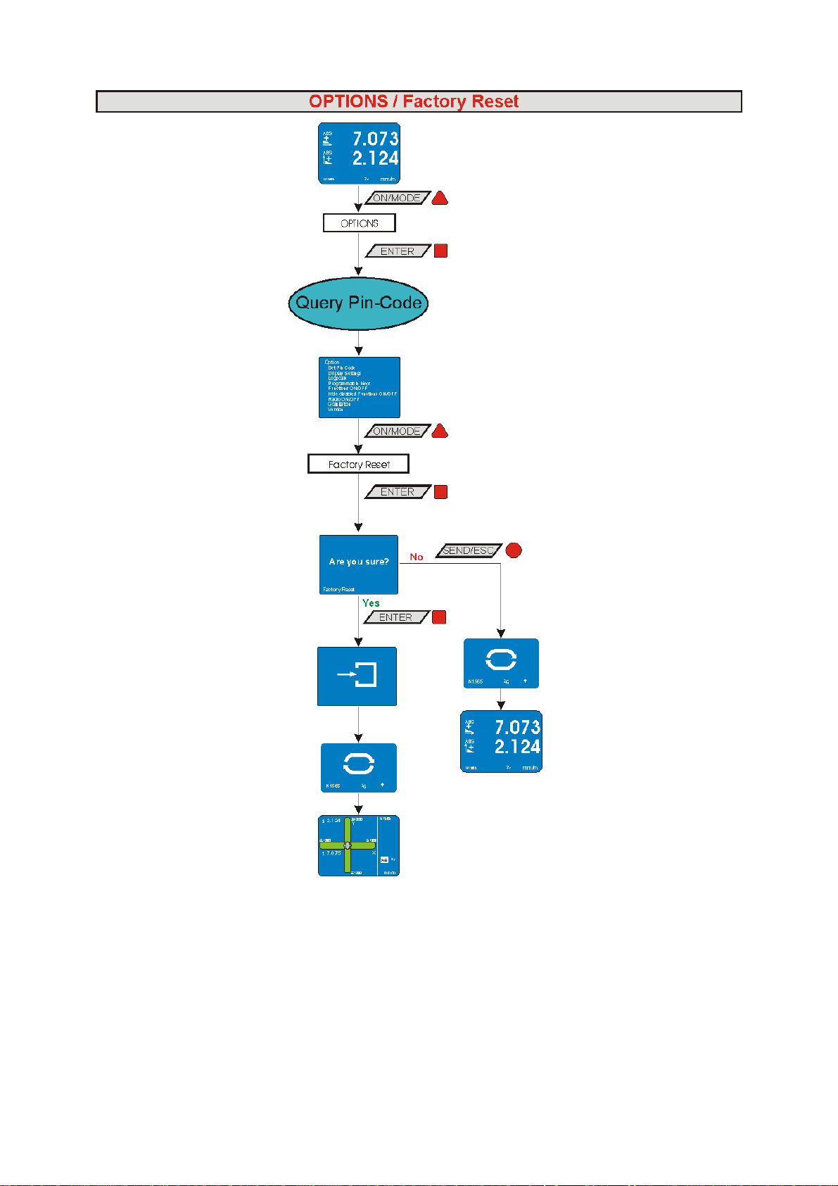
B11 RESET TO FACTORY SETTINGS / FACTORY RESET
page 60 of 65 pages
Page 61
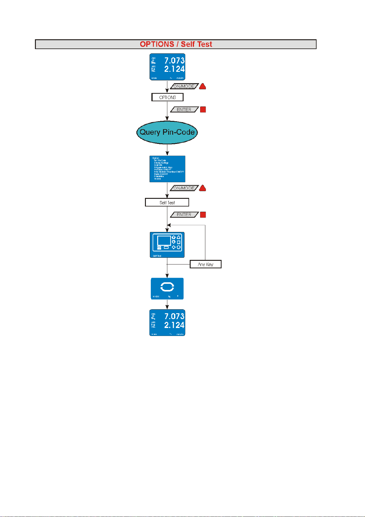
B12 FUNCTION CHECK / DEVICE CHECK
page 61 of 65 pages
Page 62
C Error Messages
After the start of the instrument the BlueLEVEL-2D performs a function check. If any defects are
detected the instrument must be returned to the distribution partner. A proper functioning can not be
guaranteed. The following error messages may appear:
Display is blinking grey mottled. Programme memory is defective
Display blinks two times grey mottled Display error
ERROR 1 General instrument defect
ERROR 2 No calibration data available
ERROR 3 Sensor not found
ERROR 4 Bluetooth not found
ERROR 5 Defective Flash memory
ERROR 6 Defective EEPROM
D MAINTENANCE
D.1 GENERAL
The BlueLEVEL-2D needs no special service other than the regular cleaning.
D.2 STORAGE/ CARE AND HANDLING OF THE BATTERIES
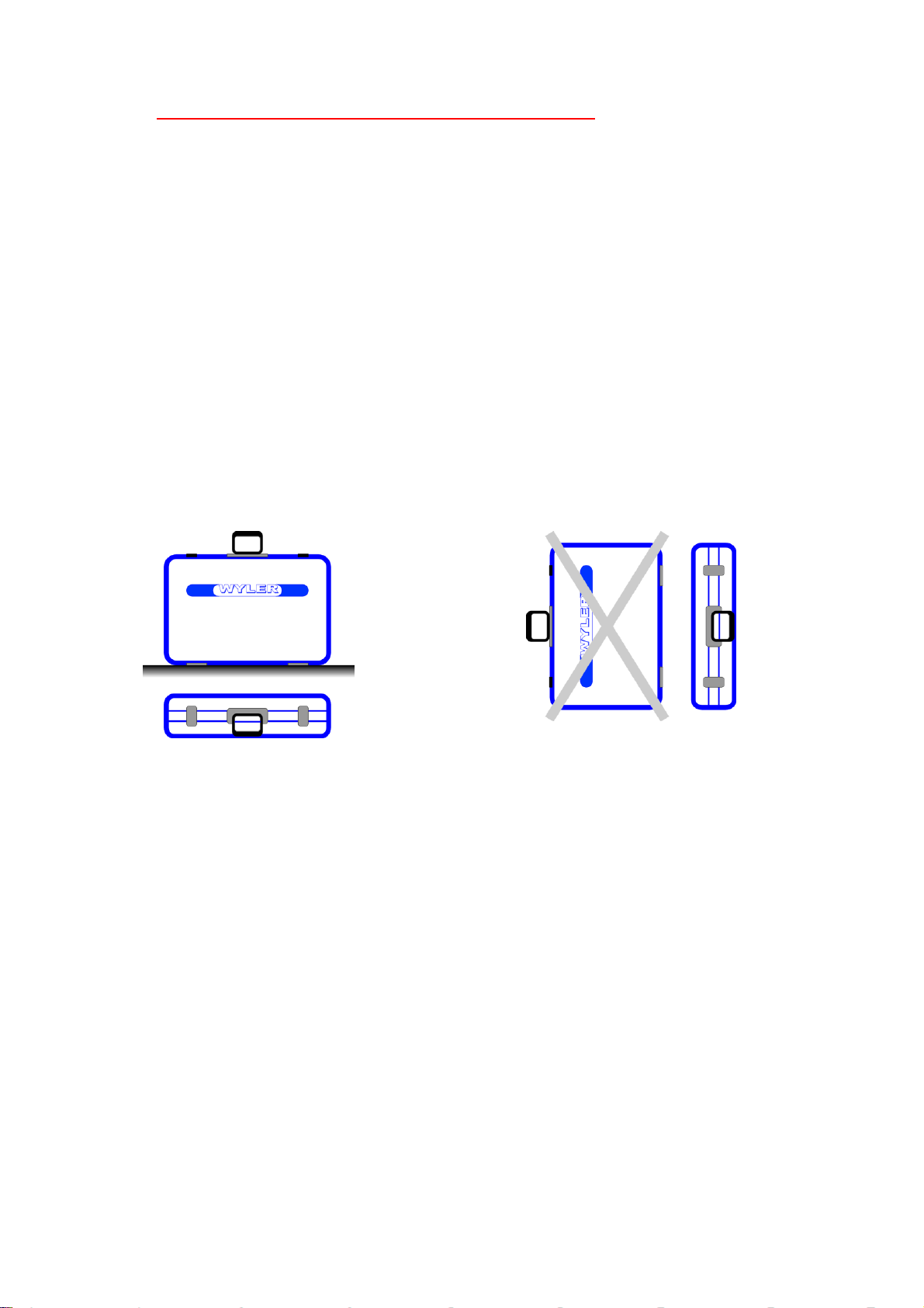
For storage periods the measuring instrument should be placed in a position i n which the instrument is
also used when measuring (upright position).
Read the instructions in your manual before installing batteries. Make sure to insert the batteries
properly, following the symbols showing you the correct way to position the positive (+) and negative (-)
ends of the batteries. Keep battery contact surfaces clean by gently rubbing with a clean pencil eraser
or cloth. Replace batteries with the size and type specified by the device's manufacturer. Remove all
used batteries from the device at the same time, then replace them with new batteries of the same size
and type. Store batteries in a cool, dry place at normal room temperature. Remove batteries from
devices that will be stored for extended periods. Don't dispose of batteries in a fire - they may rupture or
leak. Don't recharge a battery unless it is specifically marked "rechargeable." Attempting to recharge a
normal battery could result in rupture or leakage
Operating temperature (min/max): 0°C … +40°C
relative humidity: max. 85%
D.3 SPARE PARTS / ACCESSORIES
The following spare parts are available:
- Batteries, NC-accumulators
- various cables
- Infra-red Zapper
page 62 of 65 pages
Page 63

E CONFORMITY DECLARATIONS AND APPROVALS
All documents relating to
Declaration of Conformity “DoC”
FCC Compliance, Statement for cB-0946
IC Compliance
Japan Radio Equipment Compliance (TELEC)
Batteries / WEEE
can be found on our website WYLER AG, http://www.wylerag.com/en/support/certificates/
F SERVICE AND REPAIR
F1 REPAIR OF MEASURING INSTRUMENTS AND DISPLAY UNITS
Normally any instruments requiring repair can be sent to the local WYLER partner (local distributor)
who will take the necessary steps and make the arrangements for repair on behalf of the customer.
Express Repair Service, ERS
A large number of customers can not miss the instruments for a
longer period as these are in daily operation. For these cases
WYLER SWITZERLAND has created a new service called "Express
Repair Service, ERS". Employing this service the transport time
from the user to WYLER SWITZERLAND and back and thus the
complete repair time can be reduced considerably.
A simplified description of this service:
The customer announces the repair request to the local WYLER partner in his country.
The WYLER partner will inform the customer about the possibility of the ERS service outlining
the advantages and consequences of this service, such as e.g.
o reduced total repair time
o required acceptance to repair without quote up to 65 % of the price for a new
instrument
o suitable packing for air transport
o expenses of the ERS
In case the customer decides to use the ERS, the customer informs the local WYLER partner or
directly WYLER SWITZERLAND providing the necessary data.
The customer will receive all information and instructions necessary for a smooth handling, the
customer has just to pack the product suitably and to fill in a form for the TNT courier serv ice
as well as to announce the readiness to the local TNT office for pick-up. Everything else will
run automatically.
Products reaching WYLER SWITZERLAND under this service will be handled with first priority,
and the instrument will be returned using the same carrier.
The invoicing will be through the WYLER partner in your country.
Please do not hesitate to make use of this service in order to have your WYLER instrument back at your
disposal as soon as possible. In case of any questions please contact WYLER SWITZERLAND or your
local distributor, we will gladly help you to use the ERS successfully.
page 63 of 65 pages
Page 64

F2 SERVICE - AND MAINTENANCE CONTRACTS
Measuring systems are becoming more and more complex and are therefore subject to continuous
supervision in respect of quality and reliability. For this purpose WYLER AG offers the option of a
MAINTENANCE CONTRACT with the purchase of new instruments.
Such a MAINTENANCE CONTRACT offers the following services to the customer:
• Complete inspection and re-adjustment of the instrument / system in a bi-yearly interval.
• The scope of delivery includes an internationally recognised Calibration Certificate SCS for the
entire system confirming the performance after the service intervention. Traceable certificates
SCS are issued according to our accreditation as a calibration laboratory by the Swiss
authorities
• Highest priority for any repair works (actual repair work is not included and will be quoted
separately)
• Technical enhancements and modifications published by WYLER, if considered suitable
• Costs for packing and transport of the instrument(s) from the customer to WYLER and back,
either directly or through the WYLER distribution partner
• Extension of warranty period to 24 months: If a maintenance contract is signed within 6 months
of the purchasing of a new instrument the warranty period is extended to 24 month.
Options:
Depending on the customers requirement the re-calibration interval can be shortened (every year) or
be extended (every 3rd year)
The following services are excluded from all maintenance contracts:
• The contract does not include any repair work. If it is determined during the inspection or the
re-calibration process that the instrument requires repair, such work will be quoted separately to
the customer.
We help you to keep your valuable and important instruments always accurate and ready for use!
We would be glad to offer you a maintenance contract adapted to your specific requirements.
.
page 64 of 65 pages
Page 65

WYLER AG
Im Hölderli
CH-8405 WINTERTHUR
Switzerland
Tel. 0041 (0) 52 233 66 66
Fax. 0041 (0) 52 233 20 53
Homepage: http://www.wylerag.com
E-Mail: [email protected]
 Loading...