

Wykamol Flitvent Installation And Maintenance Manual
Low Energy Positive Input Ventilation Unit Installation and Maintenance
IMPORTANT NOTES TO INSTALLERS
The FLATVENT range has been curing severe condensation problems for
over 20 years in some of the worst affected properties throughout the world.
Its successful operation depends entirely upon the unit being installed strictly
in accordance with these instructions. We would, therefore, respectfully
suggest that you read through this guide in its entirety before commencing
installation and then go through this guide step by step to ensure a
satisfactory completion.
Whilst the installation of the Flatvent unit may be achieved by a suitable
craftsman, the provision of the electrical supply and the connection of the
unit to the mains must be carried out by a qualified electrician.
The unit has a 5 year warranty starting from the day of delivery and includes
parts and labour for the first year. The remaining 4 years covers parts only.
This warranty is conditional on the following:-
a)
T
ha
t the unit is installed strictly in accordance with this guide.
b) That the unit filters are removed and cleaned or replaced at the
r
ec
ommended in
t
er
vals.
The unit represents a significant financial outlay on the part of the
user/specifier and the unique 5 y
ear war
rant
y is impor
tant t
o them. We make
a point of advising them that the installer is provided with detailed
instructions regarding installation/guarantee registration and therefore has
the r
esponsibility of ensuring that the unit is guaranteed for the user/specifier.
1.0 INST
ALLATION
The unit is designed to take fresh air from outside, clean the air, warm it (if fitted
with heat
er) and discharge it into the central hallway via a system of ducting
supplied by the installer. The dwelling internal air discharge grille is usually
installed at high level in a central location within the hallway, although
discharging the air down the length of the hallway (away from the front door)
should also prove acceptable. Unit performance may be enhanced if an existing
heat source can warm the discharged air eg. by locating the discharge grille
above a radiator.
Before commencing installation decide the best position for the unit and where
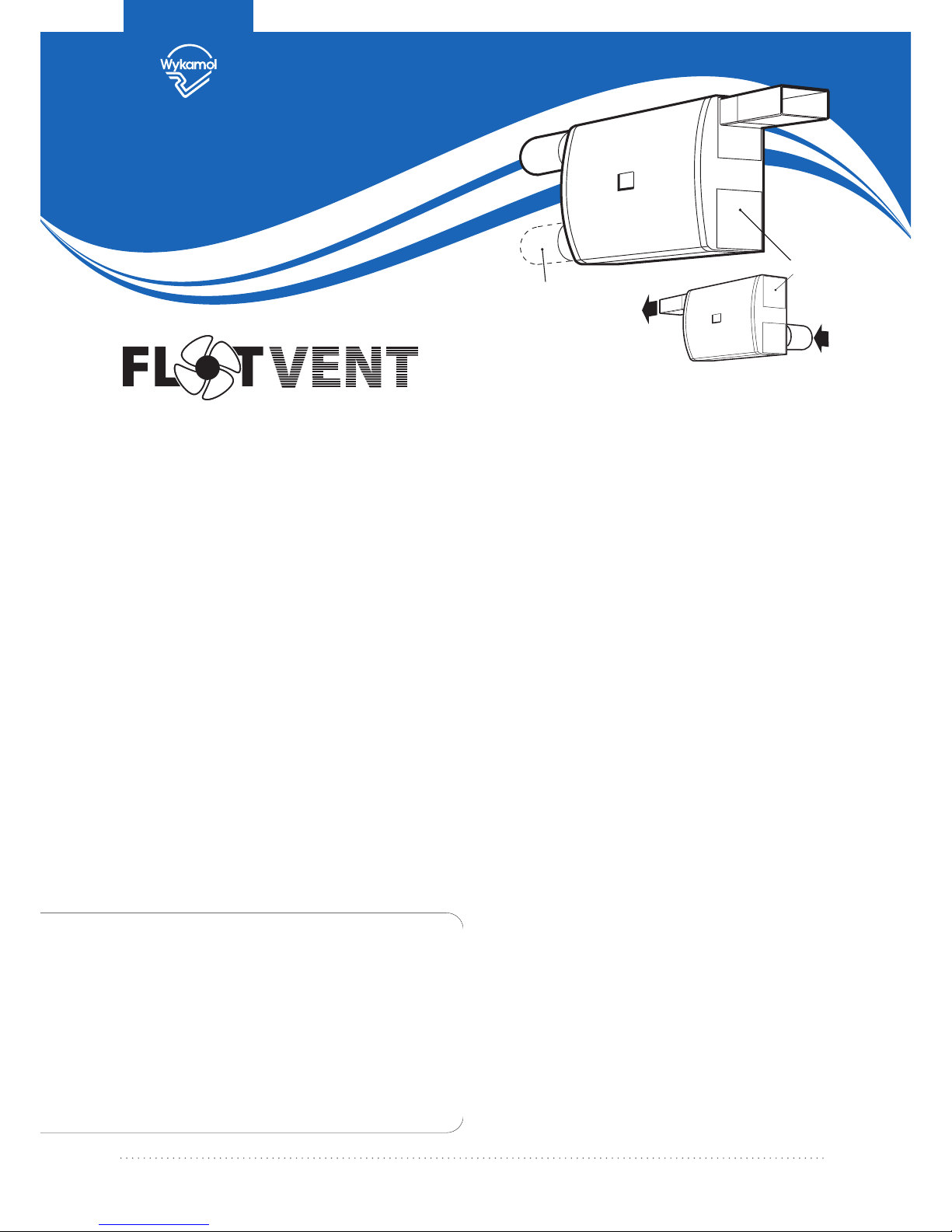
the fresh air input air is to come from and be discharged to. The unit can be
installed in many different configurations and is supplied with enough
interchangeable spigots to enable it to be used with either round (100mm) or
rectangular ducting (121mm x 60mm). The unit can be turned through 180o to
any angle if required.
Figure 1. (above) Typical installations show unit with top discharge.
FIXING THE UNIT TO THE WALL
The unit has four mounting pads. Mark through these pads when the unit is in
the correct position. Drill and plug wall with suitable fixings. Remove PCB cover
and f
eed the electrical supply cable through the grommet hole (standard
1mm three core lighting cable is recommended) in the rear of the unit screw
unit t
o wall
.
POINTS TO CONSIDER
1.
T
he inlet duc
ting should be k
ept as shor
t as possible t
o a
void
condensation build up on the ducting surface (see figs 5/6).
2.
C
an the dischar
ge g
r
ille be located to take advantage of existing
heat sources?
3.
Find the shortest, most direct route from outside of the unit and then to
the discharge grille using the least number of bends (these bends
incr
ease the air
flow resistance).
4. Note the location of any joists, pipes, electrical cables etc.
5.
Allo
w adequat
e access t
o the fr
ont cover to allow filter cleaning?
6. Refer to the relevant Building and Electrical Regulations.
DATASHEET
W
her
e the sy
st
ems ar
e installed in flats where regulations require the provision of a
protected entrance hall or protected enclosure and the outlet of the systems are
within that enclosure it is necessary to ensure that the safety of the enclosure is not
compromised either in relation to its fire resistance or the entry of smoke. Smoke
detectors must be connected to the fan so that it shuts down if smoke enters the
ductwork. Ductwork must be of steel, with the point of fire penetration stopped, or if
non fir
e-resistant ducting is used, it must be protected in fire-resisting construction
up to the point where it penetrates the wall of the protected entrance hall or
pr
ot
ec
t
ed enclosur
e
.
Where the systems are installed in flats where these regulatory
pr
o
visions do not apply
, good installa
tion practice should be observed; for example
the use of smok
e det
ectors to control the fan, to ensure that occupant safety levels
are not reduced. For more information please refer to the Building Regulations,
Approved Document B (Fire safety) – Volume 1: Dwelling houses (2006 Edition)
IMPORTANT
Rear entry
‘Blank off’ plate
Installation &
Maintenance
Figure 1.
T
ypical installations show
unit with t
op discharge.
Alternative inlet
position
Rear entry
‘Blank off’ plates
FITTING THE DEFLECTOR PLATE
Fit deflector plate into scroll cover as shown below. Once fitted the assembly
can be slotted into the scroll and clipped firmly in place.
TRANSFORMATION PIECE
This should be on the appropriate scroll outlet. The transformation piece
should be fitted into the chosen outlet spigot insert, prior to fitting.
Note: If the round spigot is used as an outlet, the 115 x 55mm clear blanking
plate will need to be fitted (as shown). This plate should be prevented from
movement by the use of silicone sealant.
INLET/OUTLET GRILLE INSTALLATION
I
f a flyscreen is fitted it should be removed from both the internal and
external grille.
Note: When installing the internal grille, the louvres MUST SLANT
UPWARDS to ensure the correct air circulation and the avoidance of
unpleasant downdraughts. The outside wall input grille louvres MUST
SLANT DOWNWARDS.
Standard 100mm dia ducting or 121 x 60mm ducting is used to connect the
Flatvent to the input and discharge grilles.
FIXING ALL NECESSARY DUCTING
A full range of ductwork and ductwork ancillaries are available. Please contact
Flatvent for further details.
2.0 HEATER OPTIONS (ORDER CODE FLAT-HEATER)
The heater kit contains a blank insert with a cut out for the switch. This blank
can be fitted into any appropriate opening. It is important that the switch is
fitted so that the terminals are at the bottom.
SETTING UP THE CORRECT AIRFLOW DIRECTION
Figure 2.
Figure 5. Side input installation.
Figure 6. Rear input installation (view from above).
IMPORTANT
T
he internal grille must not be placed within 1.5m of a smoke alarm.
Input grille
(louvres slant
dow
nwards)
100mm dia/121x60mm
rectangular ducting (note input
side ke
pt as short as possible)
100mm dia/121x60mm rectangular ducting
Out
side wall
Room (typical)
Alternative
spigot positions
Fla
tvent
Discharge
grille (note
louvre
s
slant
upw
ards)
Hallwa
y
(typical)
Deflector plate shown fitted in left hand air discharge (viewed from inside).
Deflector plate
pinched between guide
posts as shown
Deflector plate
shown fitted in
left hand air discharge
Scroll cover
Deflector
plate
position
under
scroll
cover
Transformation
piece
Scroll cover
Scroll cover
Scr
oll
Deflector plate
position under scroll cover
Deflector plate
position under
scr
oll cover
PCB Cover
AIRFLOW
AIRFLOW
Left Hand Discharge
(when viewed from front)
Direction of rotation
(see “S etting the unit”)
Rig
ht Hand Discharge
(when viewed from front)
Dire
ction of rotation
(see “S etting the unit”)
PCB C
over
Tra
nsformation
piec
e
Figure 3.
Transformation
piece
Blanking plate
Outlet
spigot
Figure 4.
Outside wall 100mm dia ducting
Air input
Flatvent
Note alternative
spigot positions
Hallway
(typical)
Air
discharge
Switch terminal connections
Heater
Supply
Note: Switch must be inserted into cut out in the blanking plate
with the terminals to the bottom as shown.
Figure 7.
INSTALLATION AND MAINTENANCE Low Energy Positive Input Ventilation Unit
 Loading...